Creating Custom Castor Wheel Covers
by 3DPrintingEnthusiast in Workshop > 3D Printing
673 Views, 5 Favorites, 0 Comments
Creating Custom Castor Wheel Covers
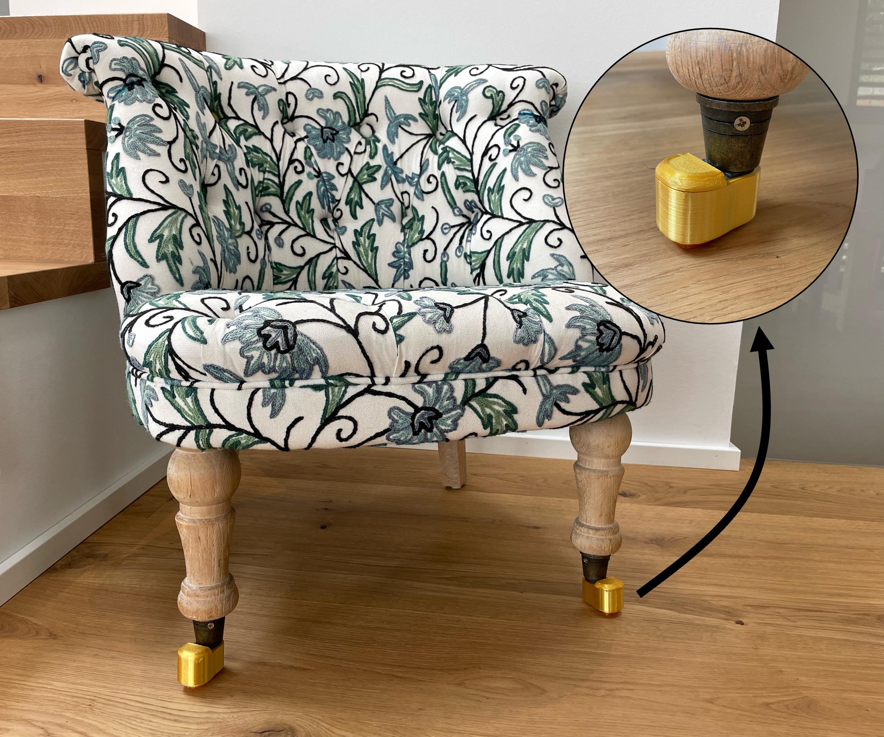
My father recently noticed that the castor wheels on some of our chairs started creating scratches in the ground. The type of castor wheel was very exotic and was not a standard size. That's why I decided to make my own cover that would safely encapsulate the castor wheel.
I am a 7th Grade Student at the Maria von Linden Gymnasium in Germany
Supplies

Supplies
- PLA/ABS/PETG Filament
- TPU Filament
- Hot Glue
Tools
- 3D Printer
- Fusion 360 CAD Software
- A Camera/Phone
- Hot Glue Gun
Taking Reference Photos
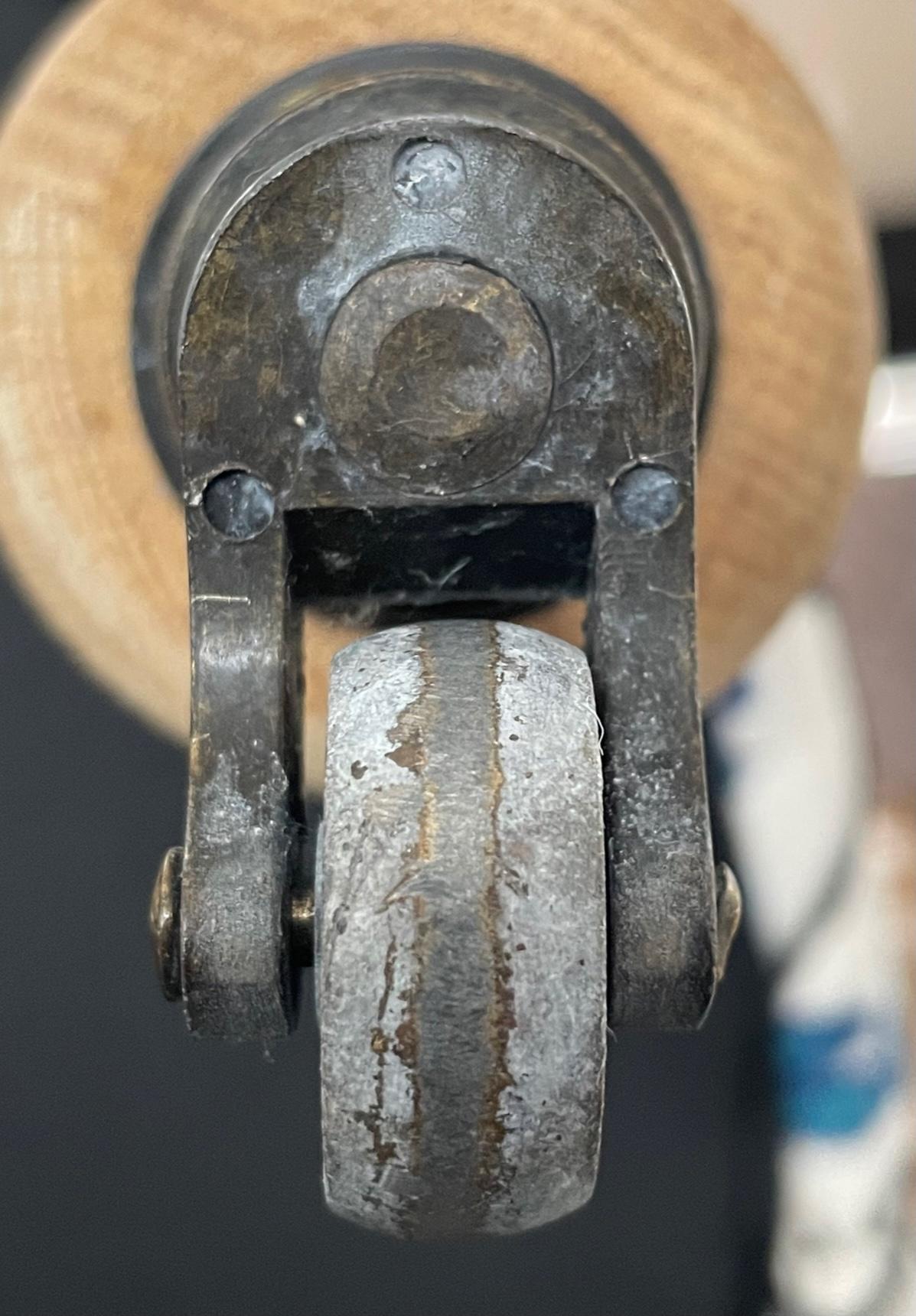
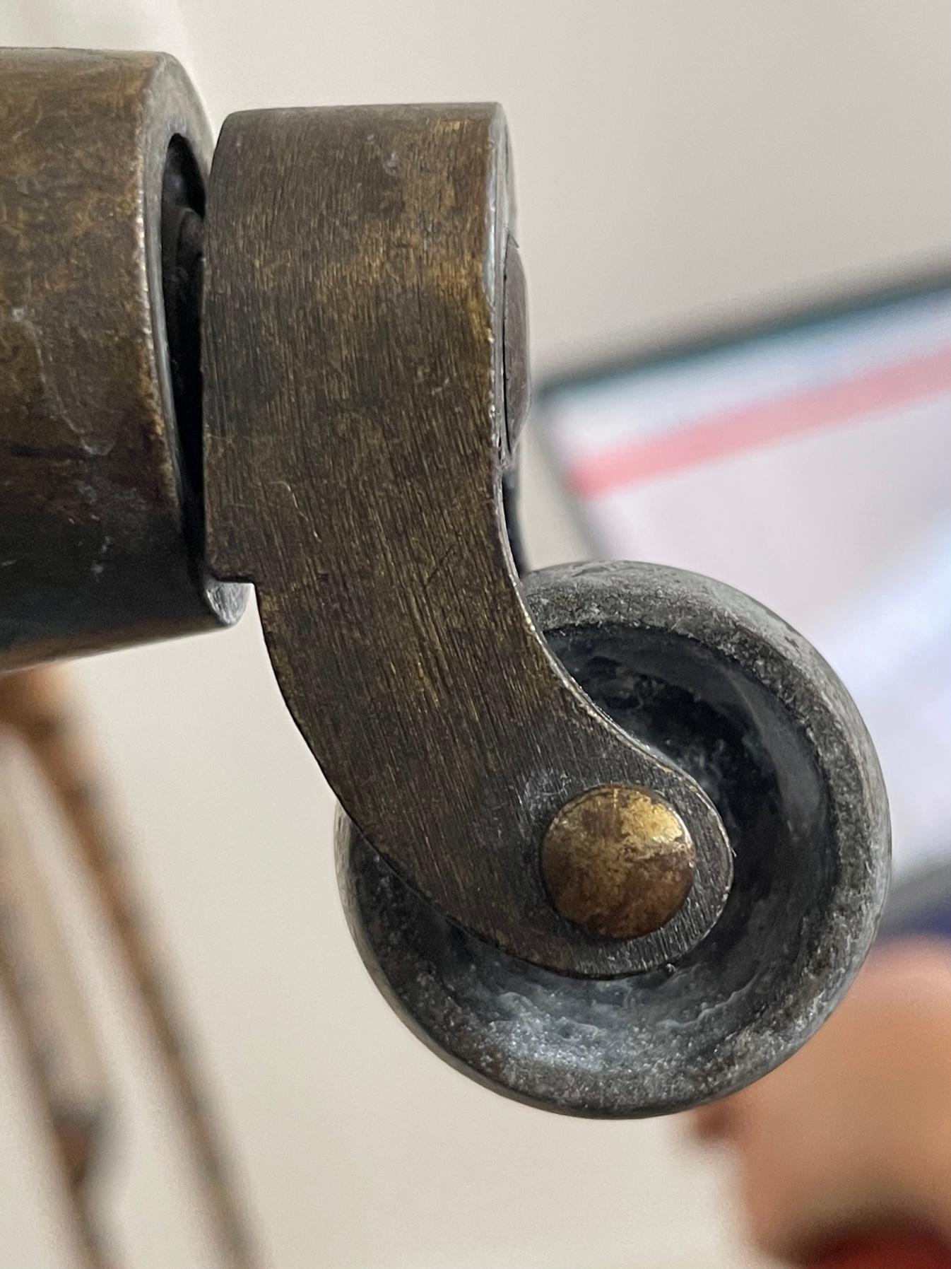
- Firstly, take some reference photos of the chair you are creating caps for
- Take a photo from the bottom and the side
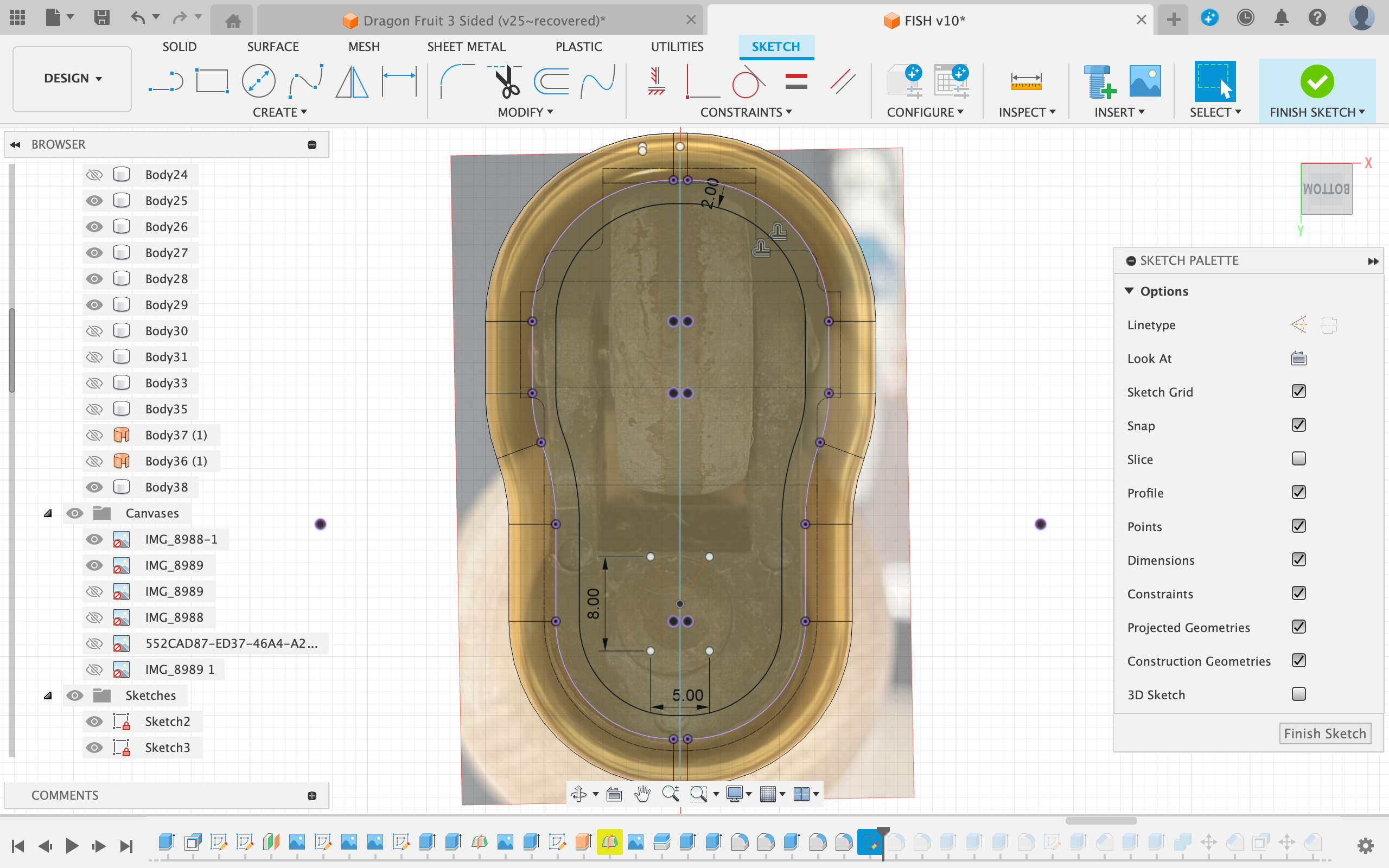
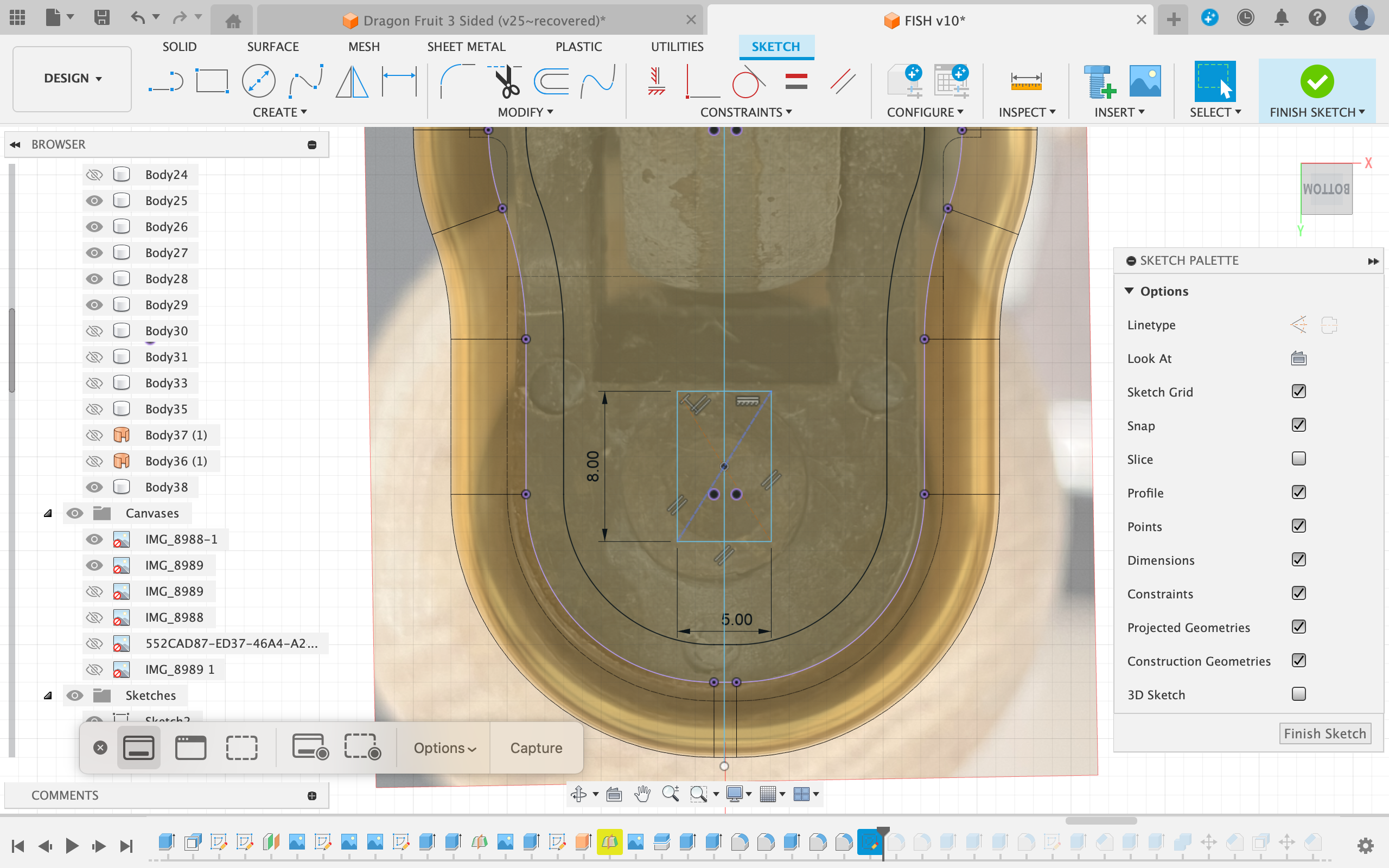
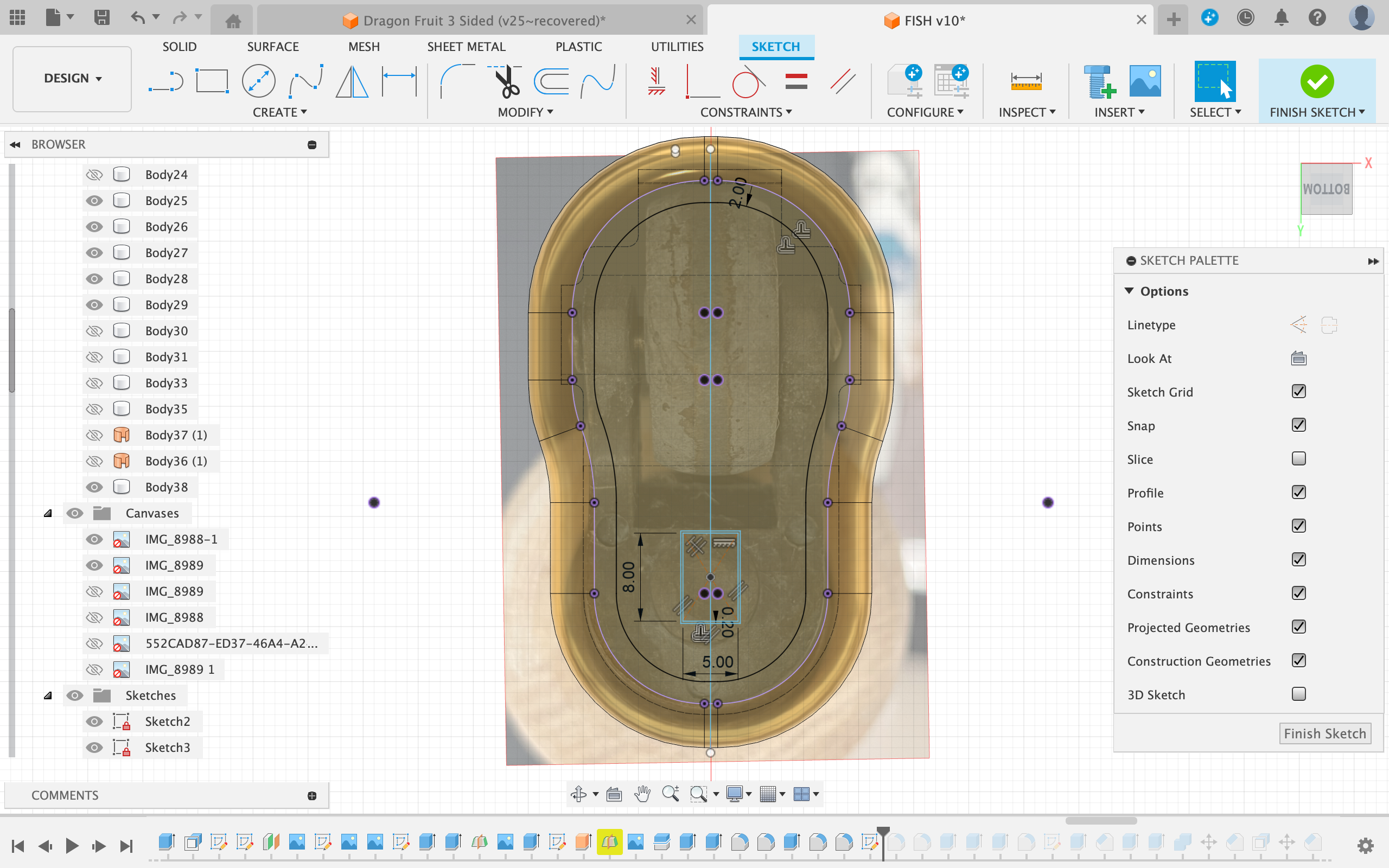
Inserting the Photos
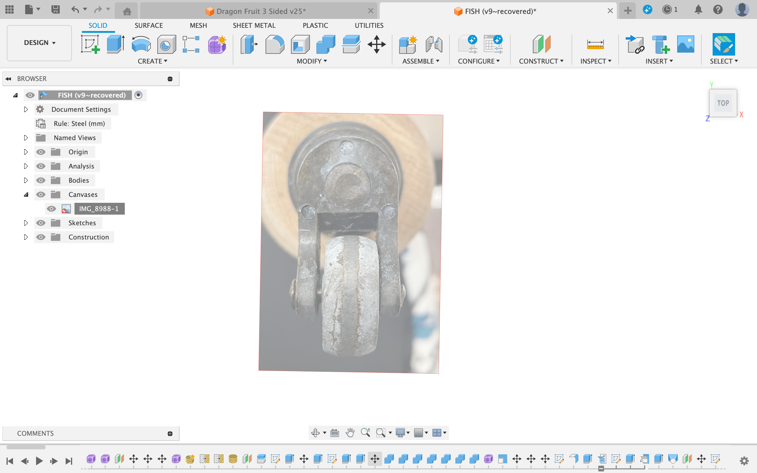
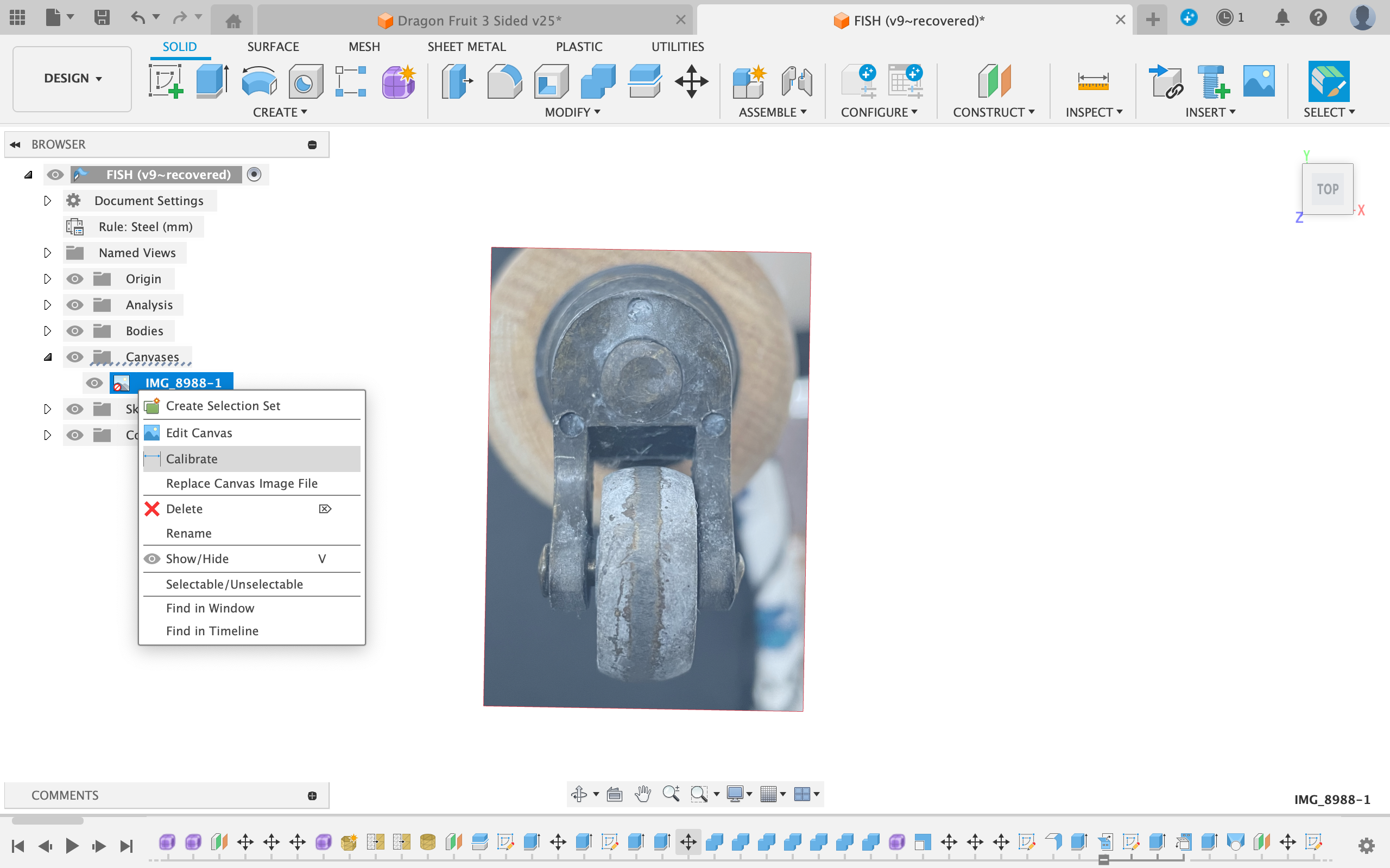
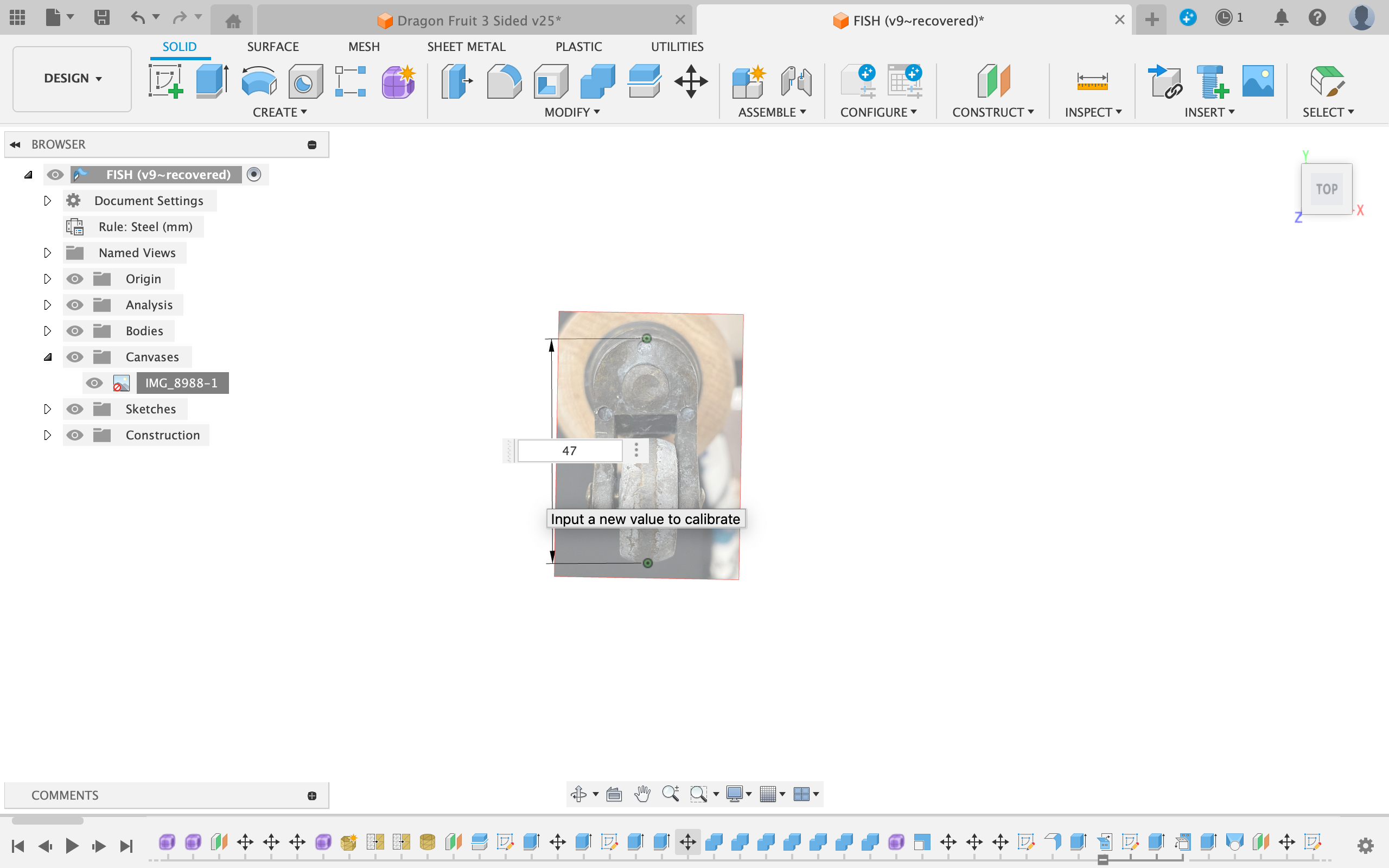
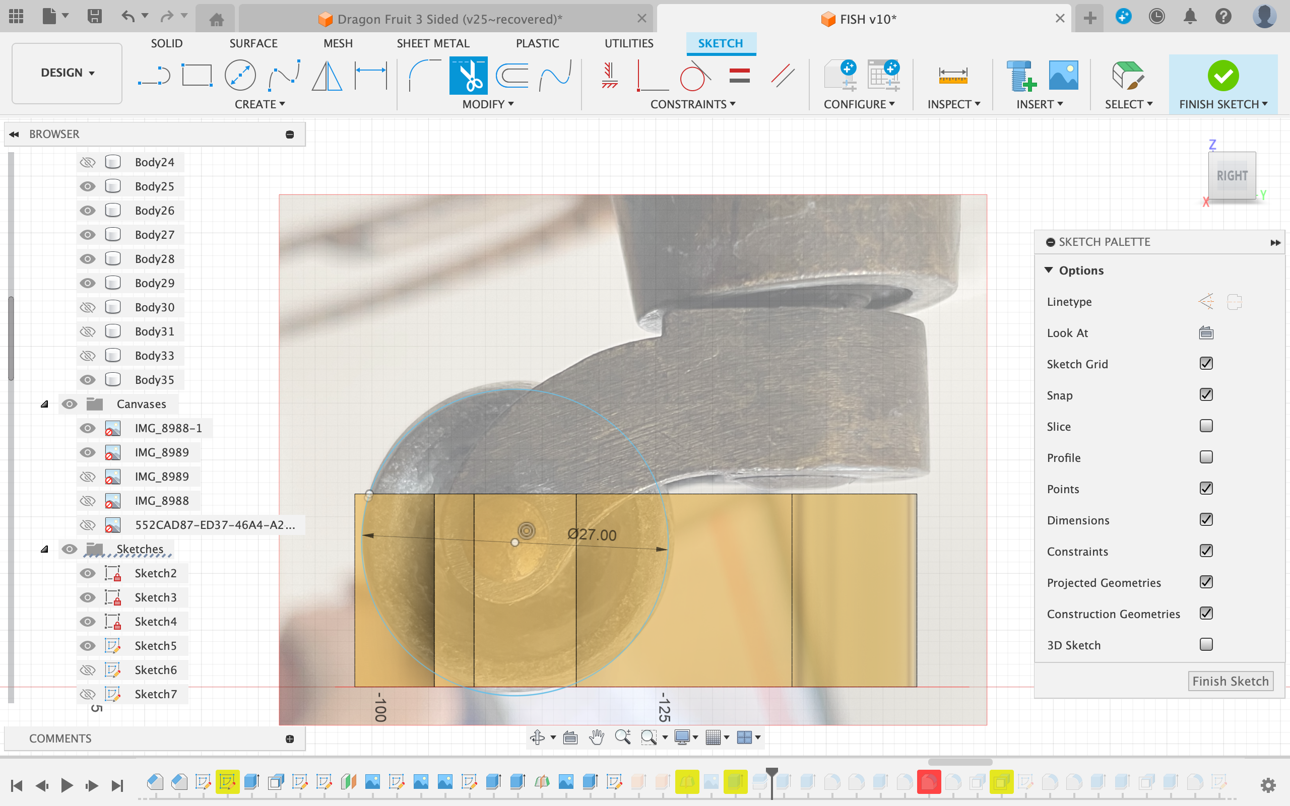
- Bring the bottom-view photo of the chair foot into Fusion on the xy plane using the "Insert Canvas" feature
- Scale the photo using the calibrate tool by right-clicking the photo in the left browser
- Select two points that you can easily measure with calipers on the photo
- Measure the distance between these points on the real chair foot and input the value
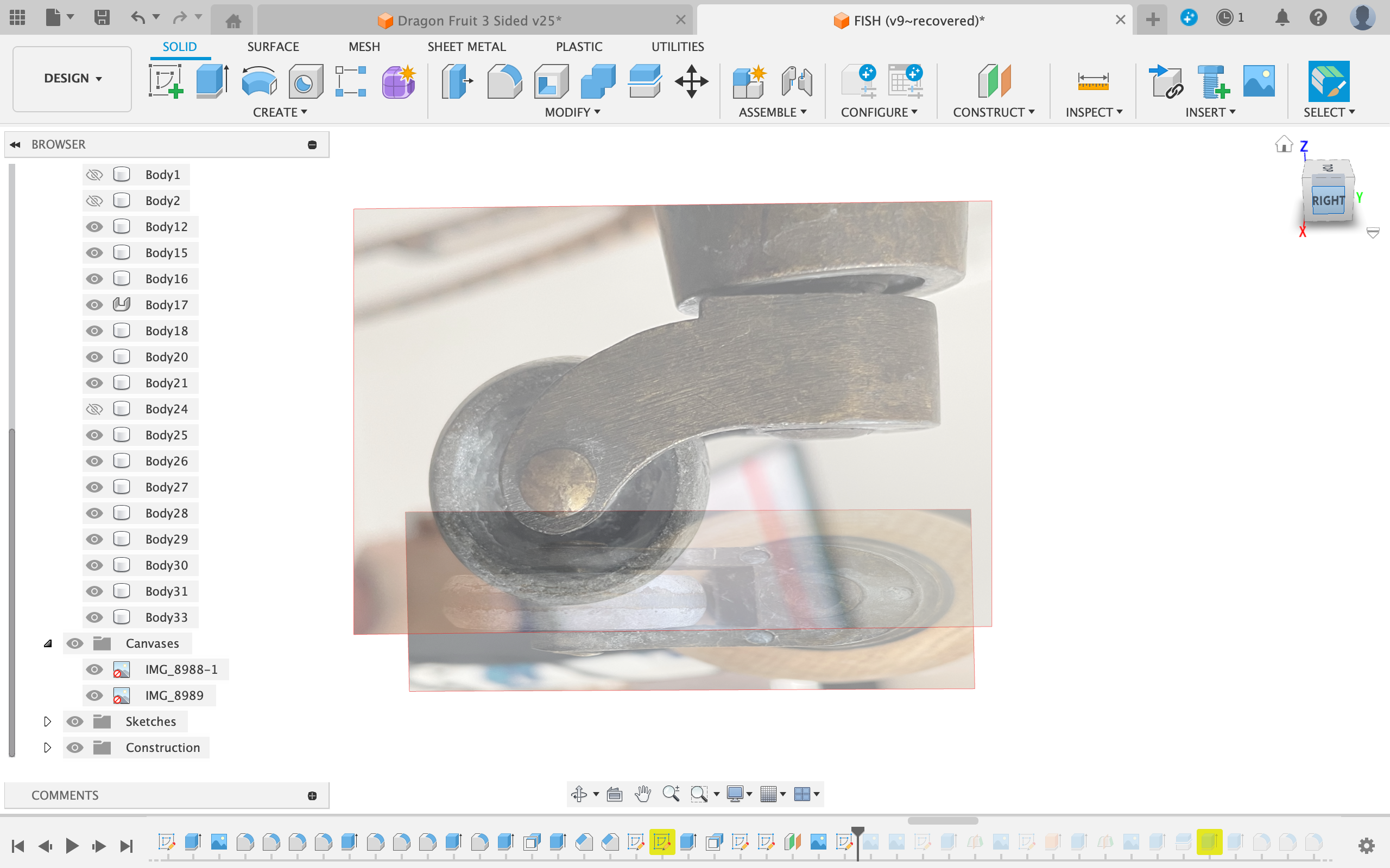
- Repeat for the other photo, but this time place it on the xz plane
Base Sketch
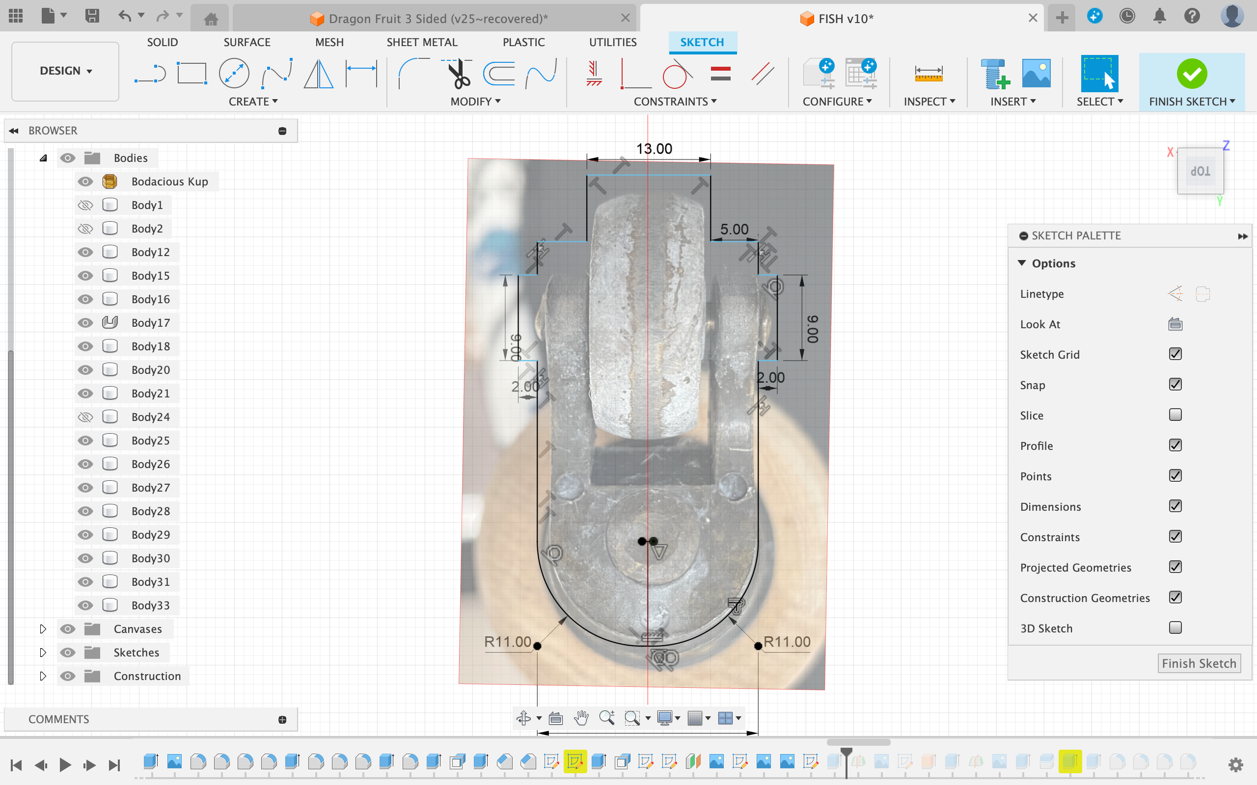
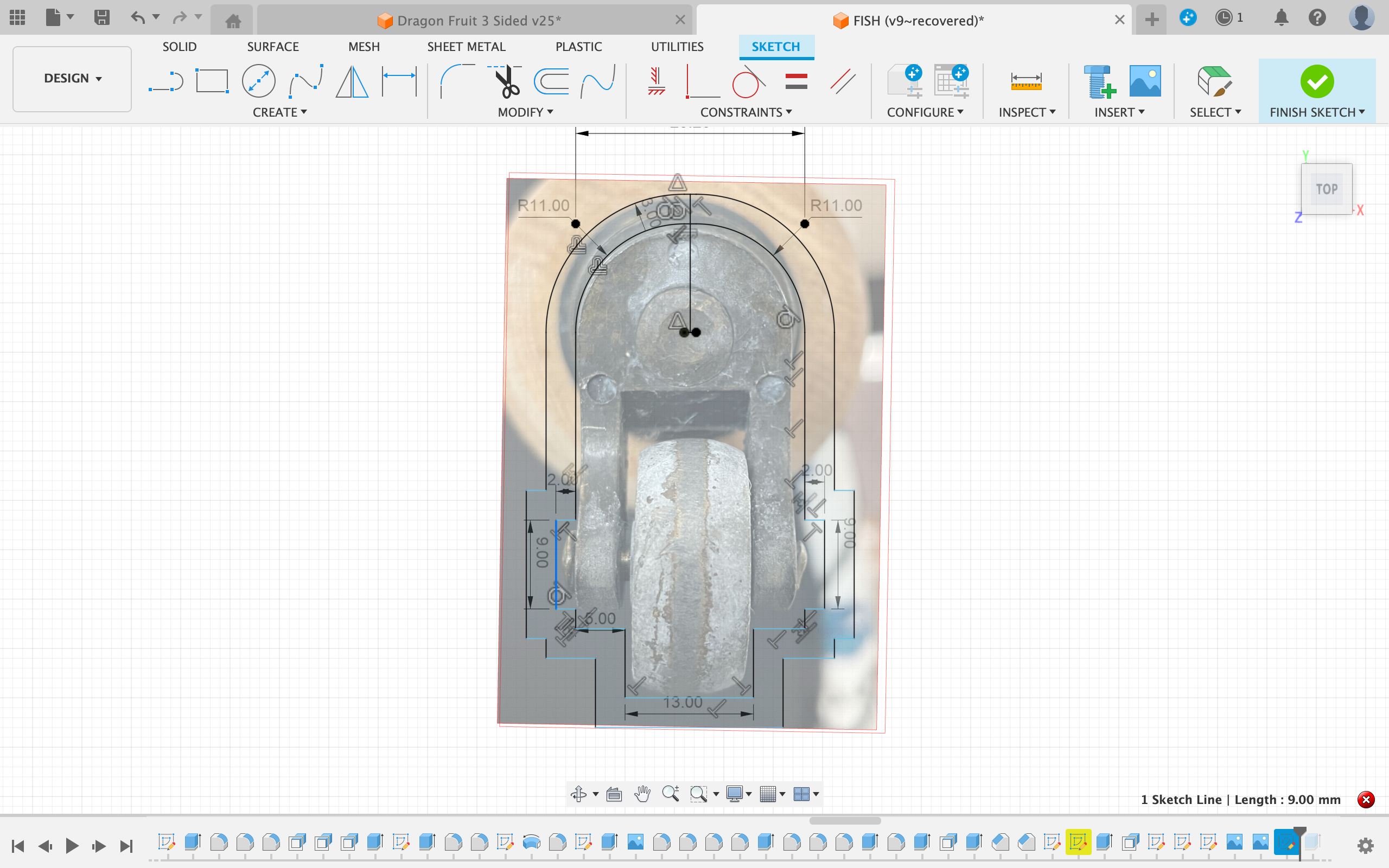
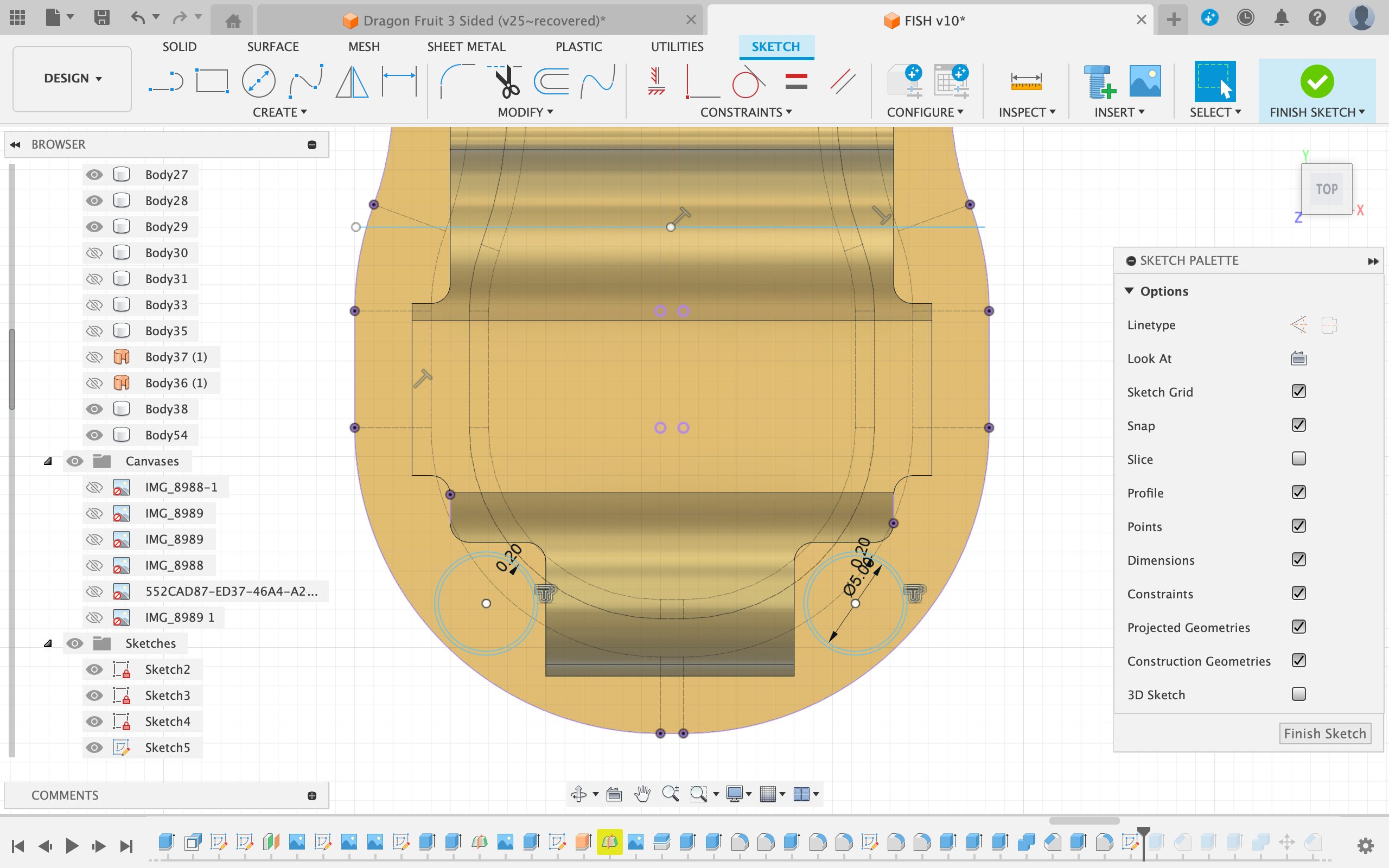
- Next, create a sketch on the xy plane (the plane on which the first picture was imported)
- Trace the outline of the shape using lines, splines and circles
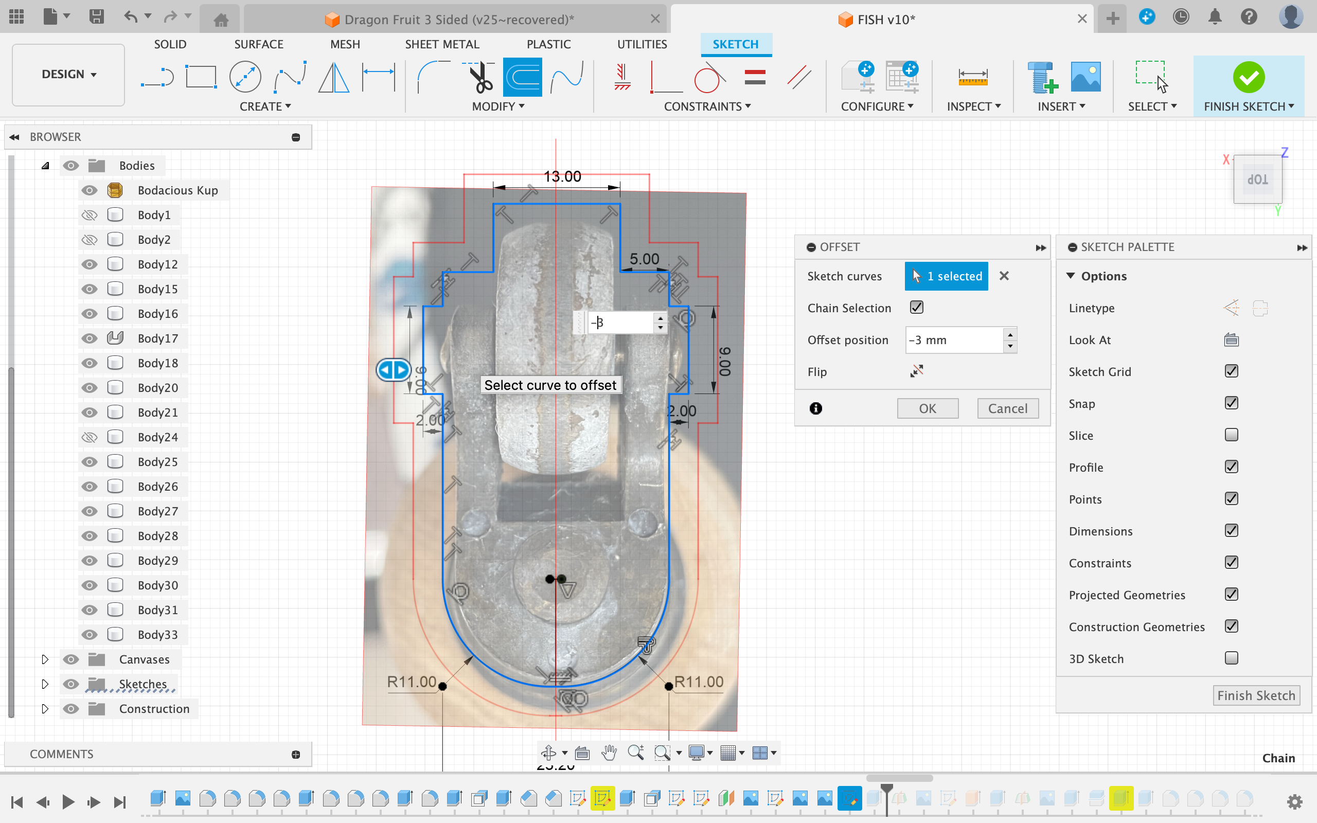
- Next apply an offset of 3mm to this enclosed shape
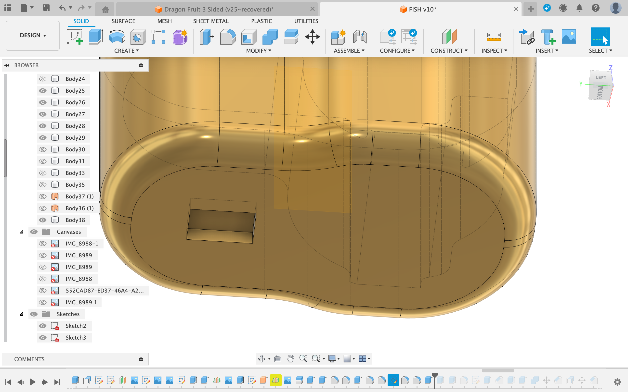
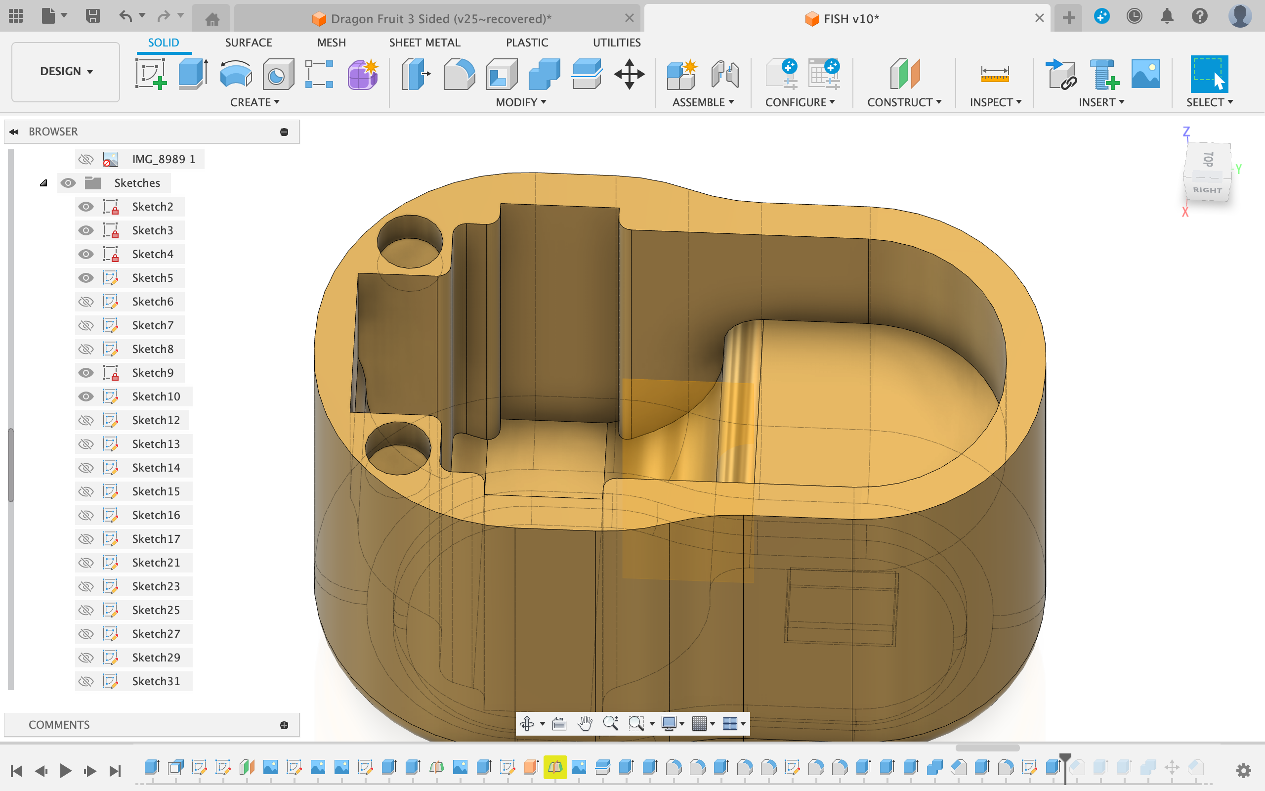
Extruding the Shape
- Extrude the inner shape up to the flat base of the castor wheel on the photo
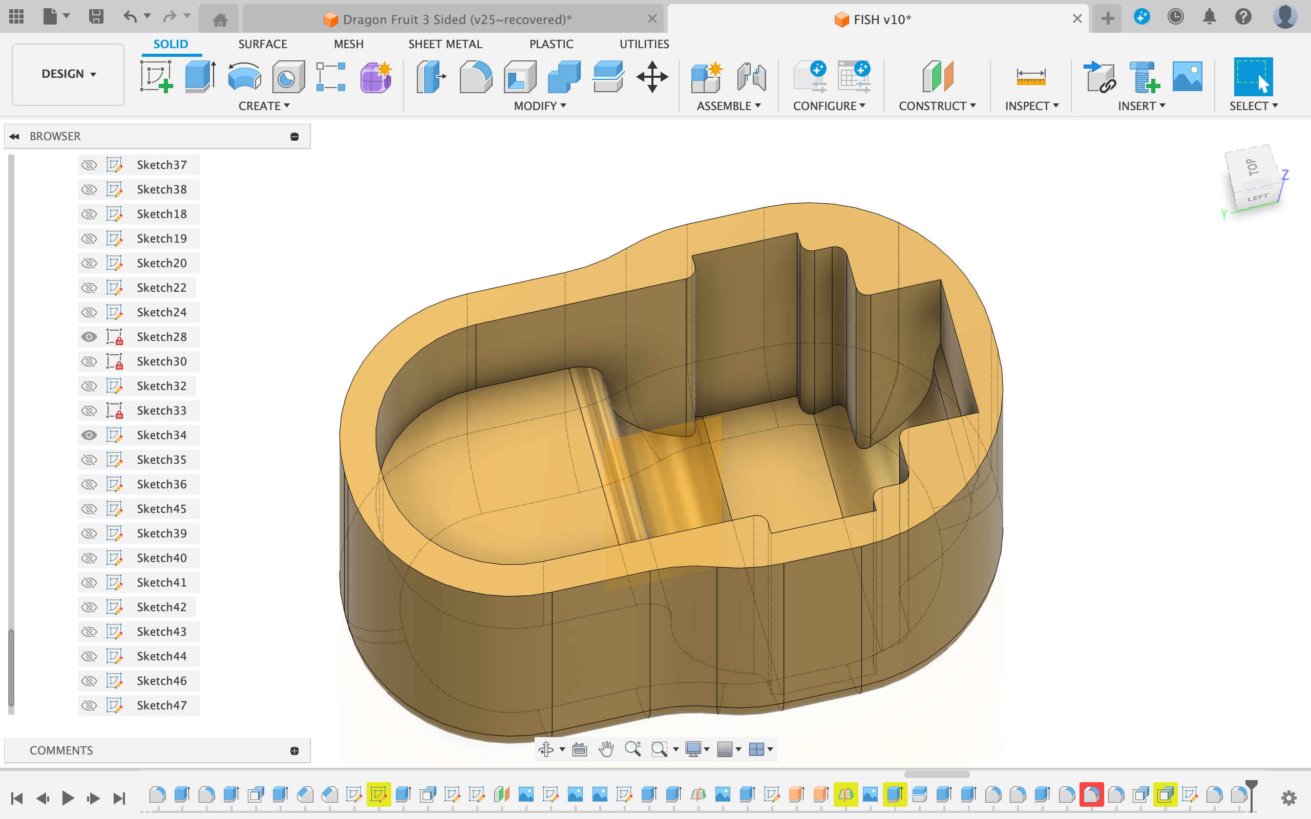
Cutout for the Wheel
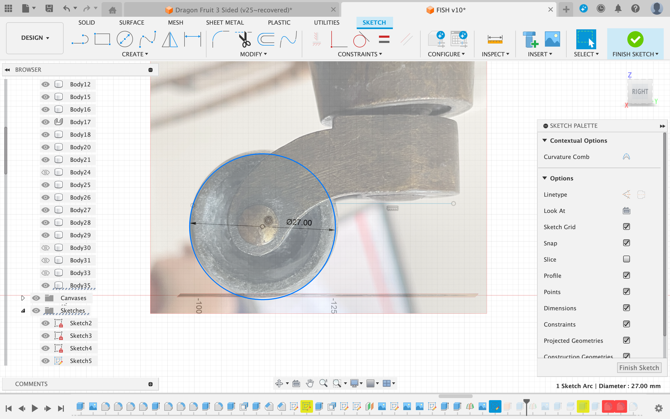
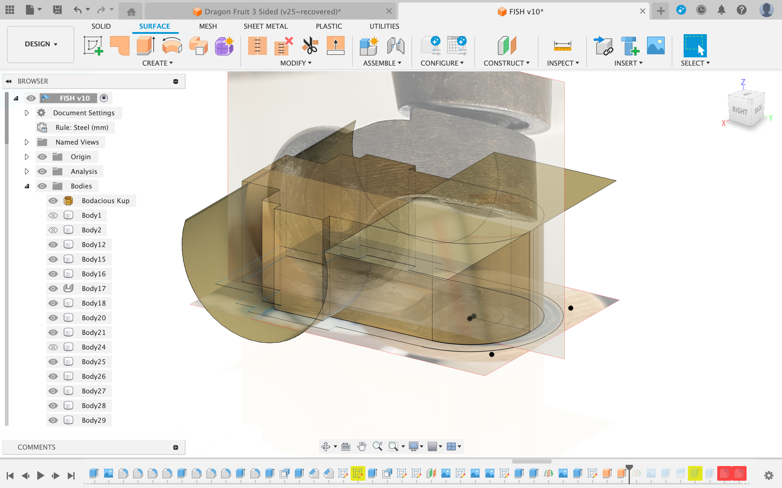
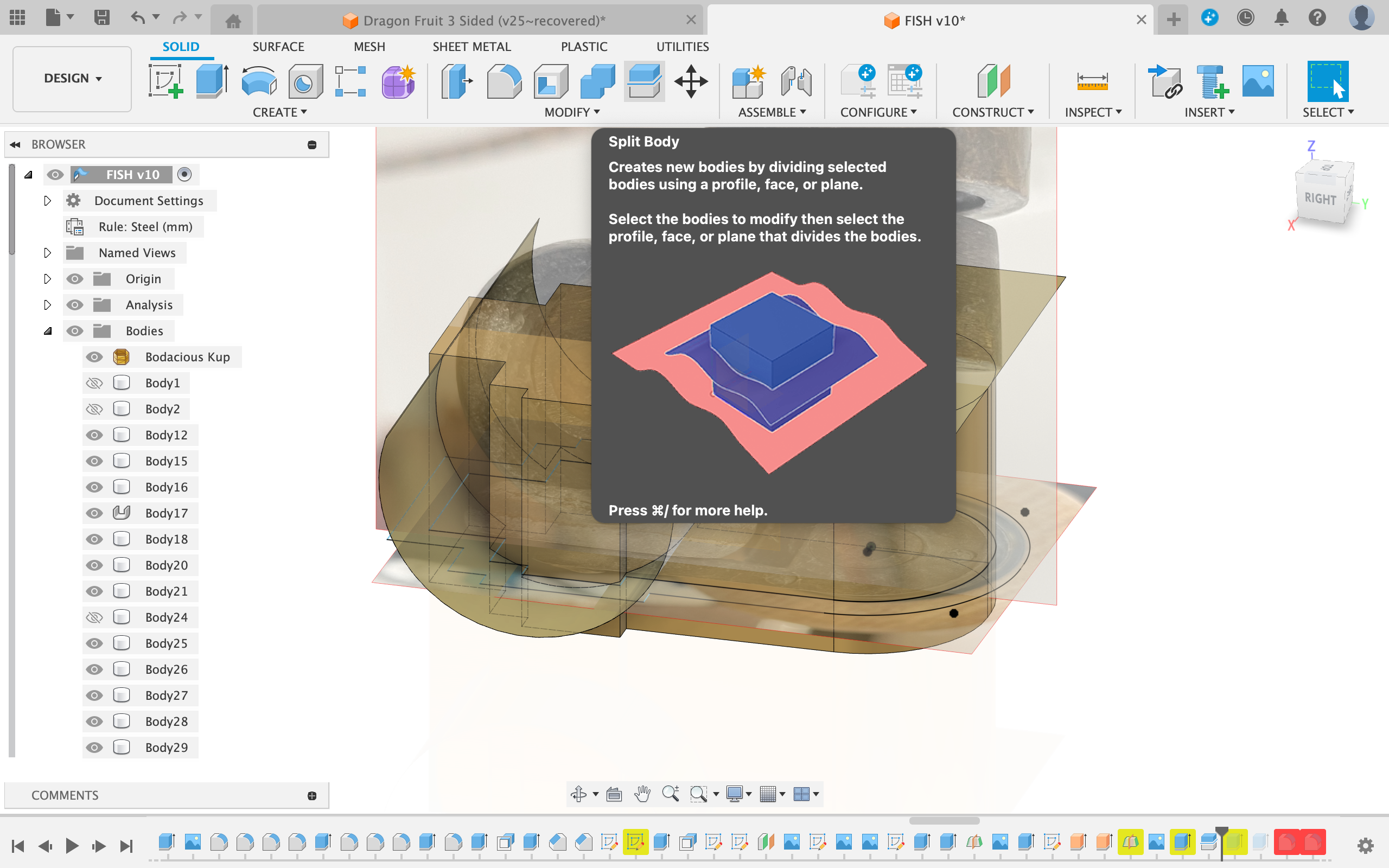
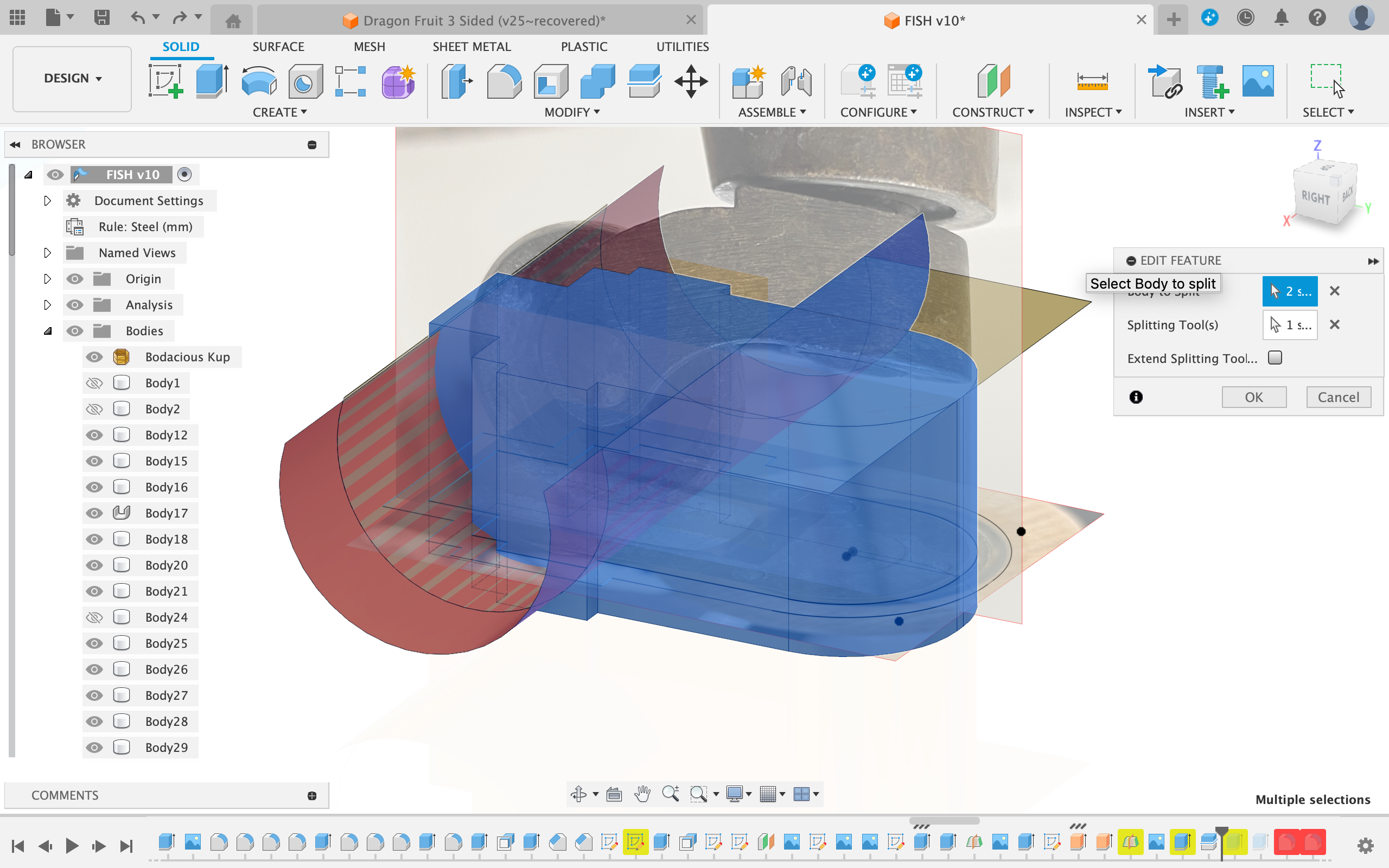
- Create a sketch on the xz plane
- Draw the outline for the wheels using a 3 point circle
- Extrude this outline in the surface environment of Fusion 360
- Use it as a cutting tool to split the body created in Step 4 into two pieces
- Delete the semi-circular cutout
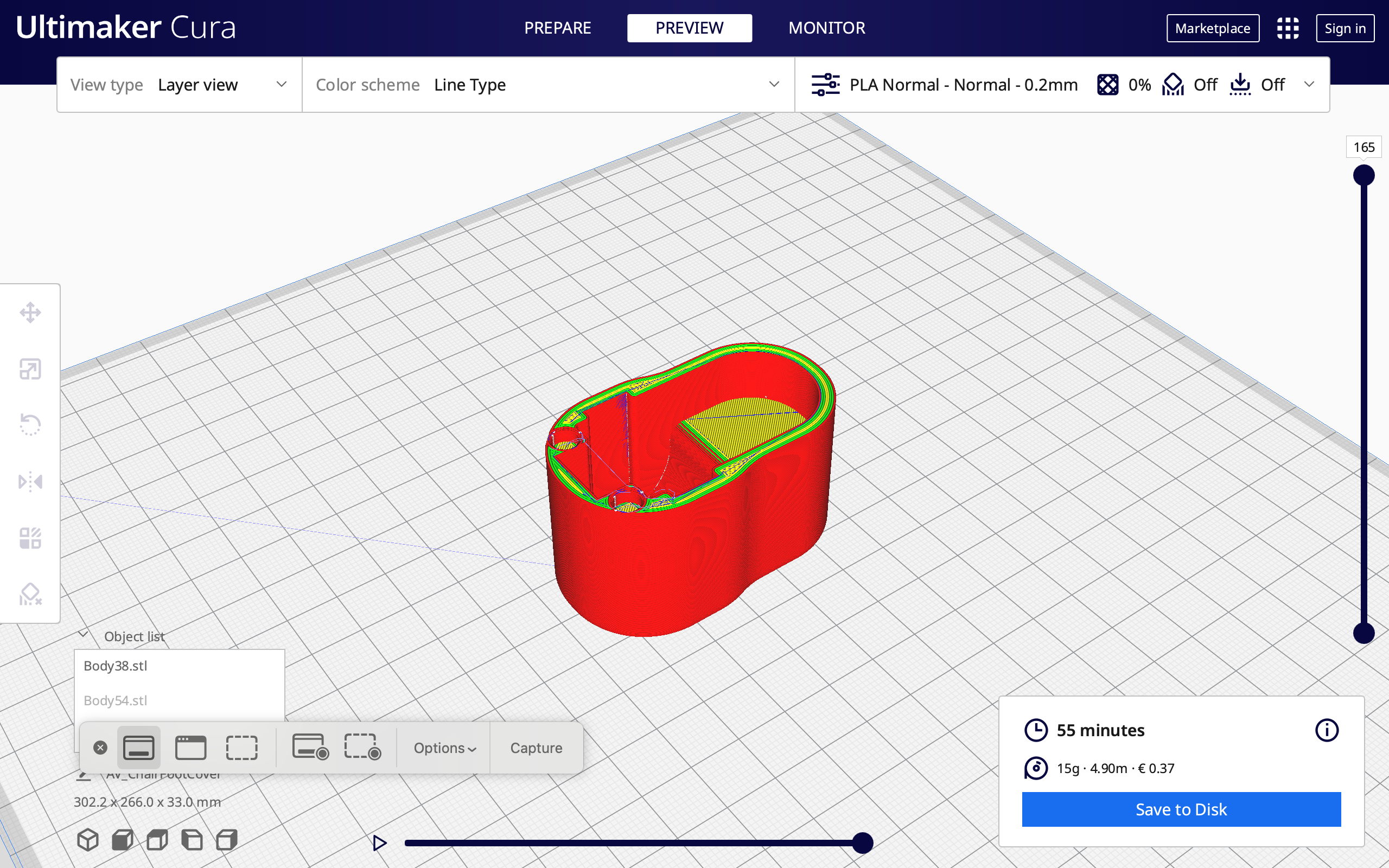
Walls
- Extrude the outer wall from the sketch from step 3 up until it covers most of the castor wheel
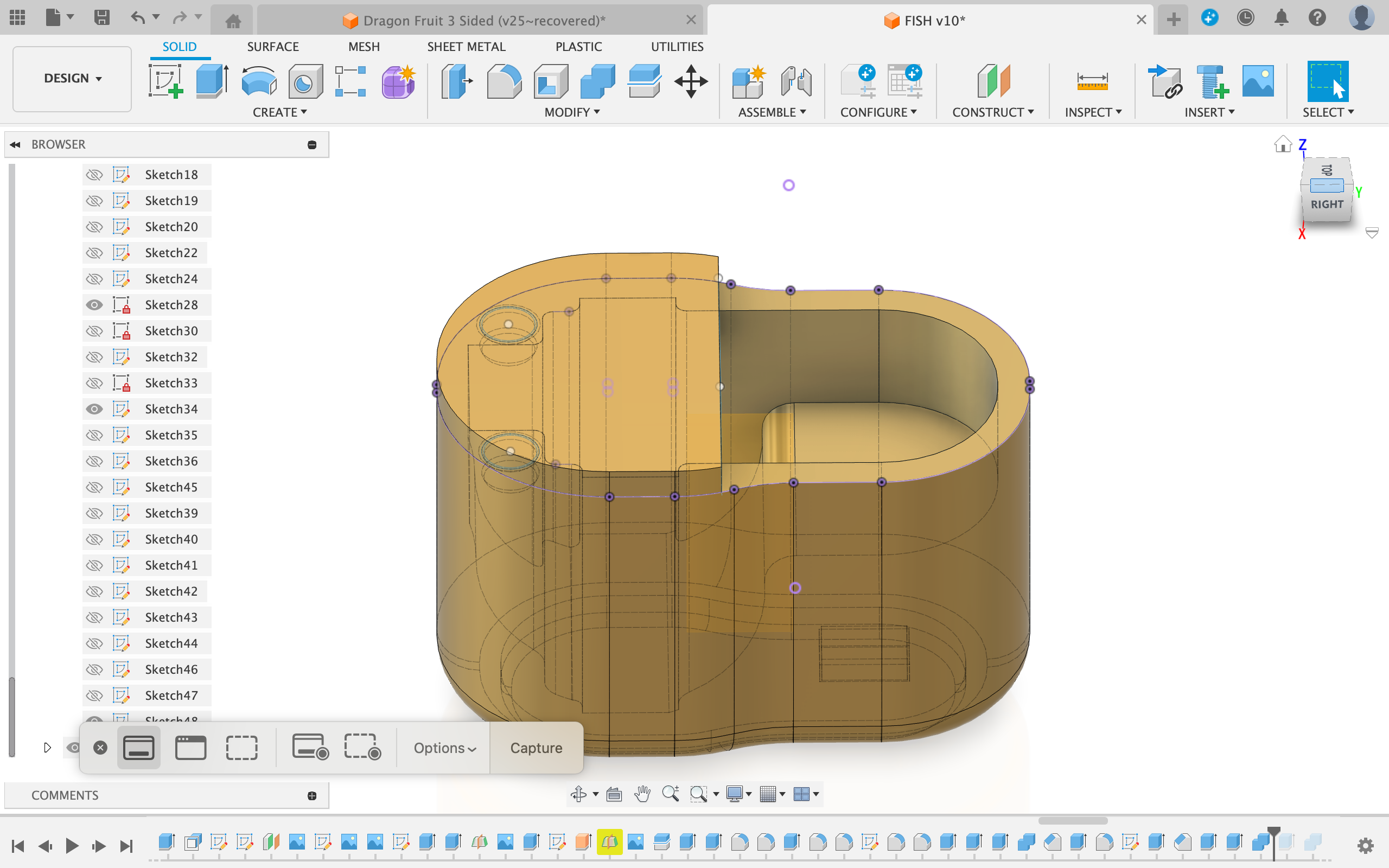
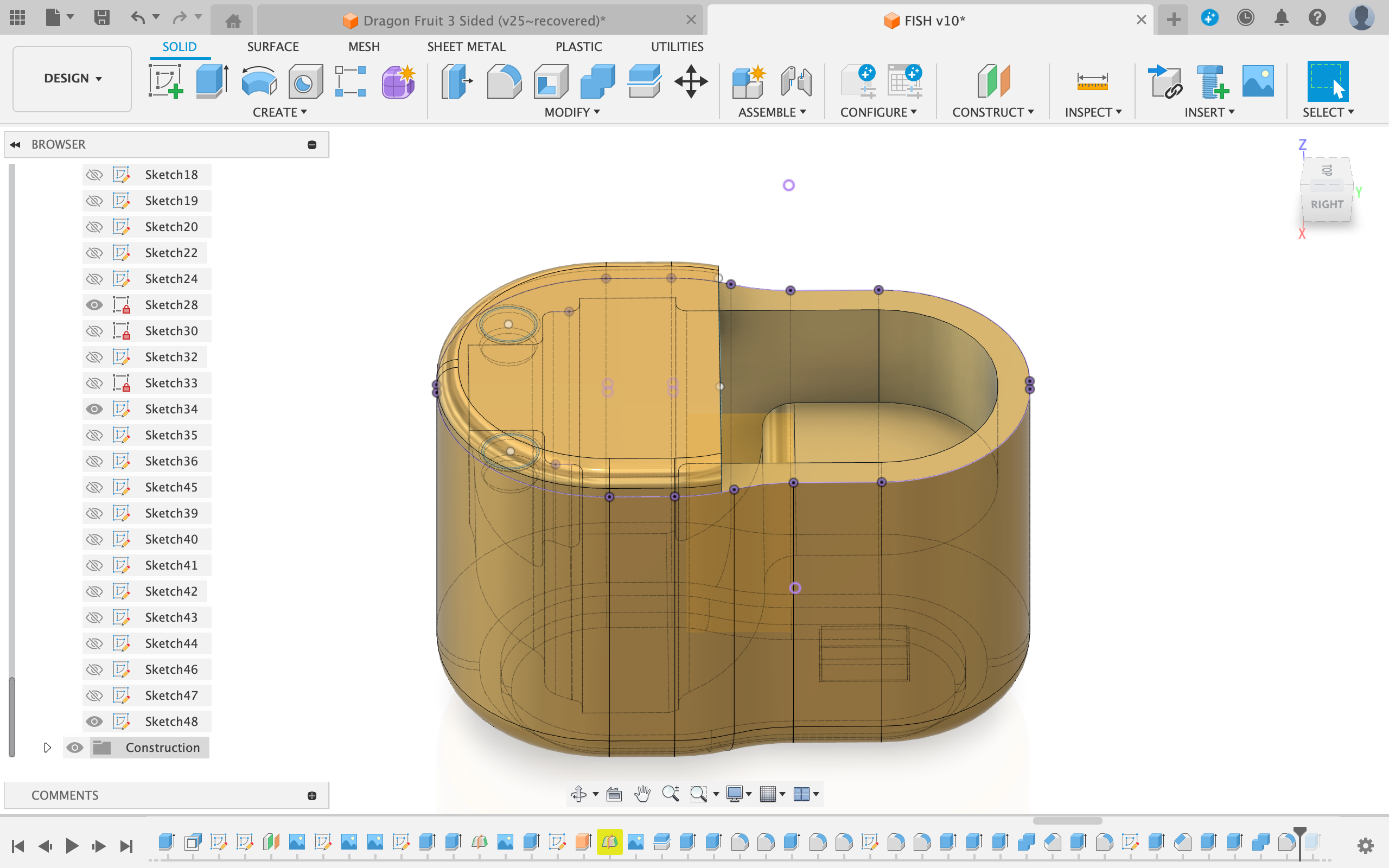
Rounding Off Edges
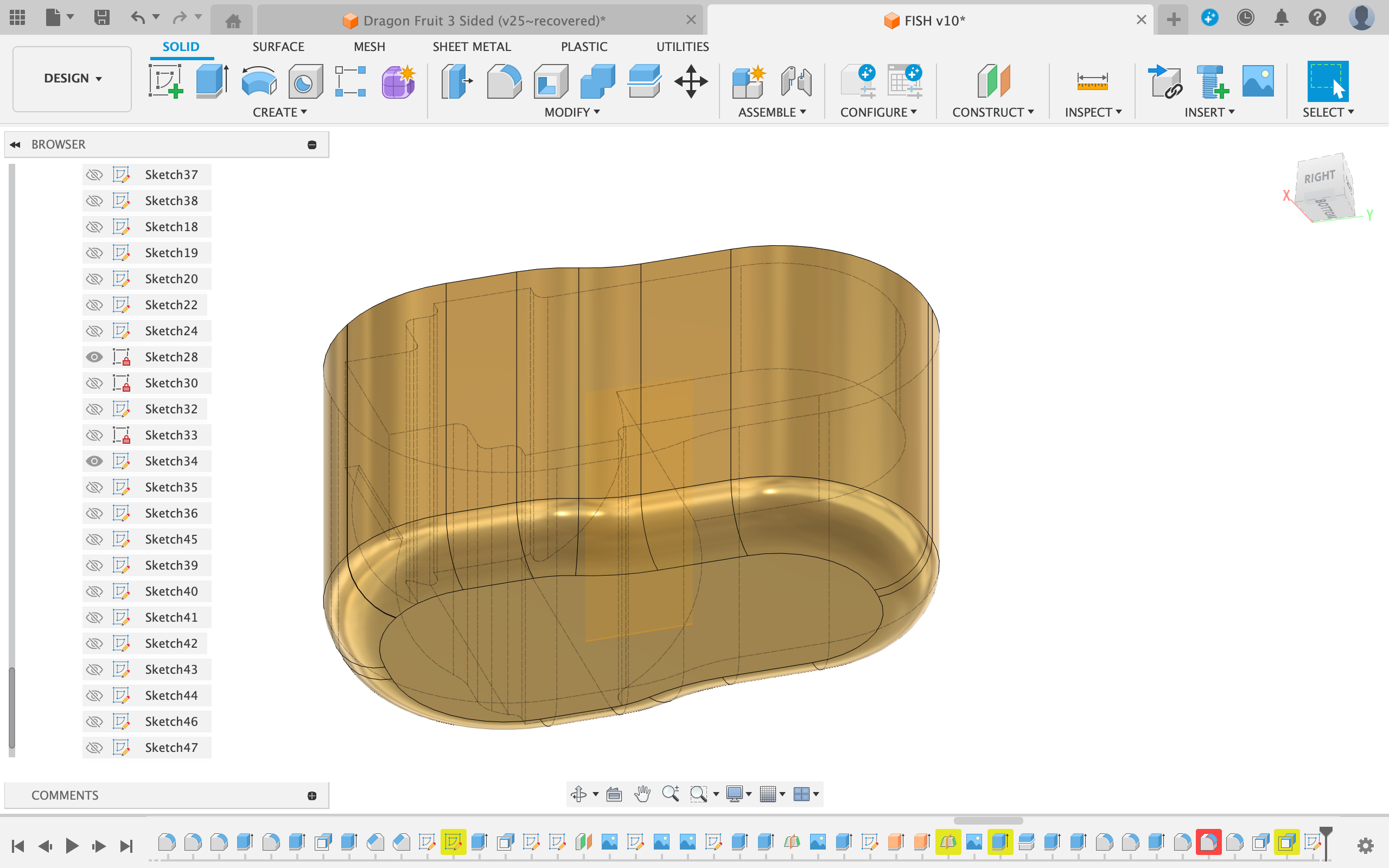
- Round off all side edges using the fillet tool
- Round off the bottom face
- Round off the inner sharp edges on the wheel cutout
Sketching a Rubber Foot
- Next, create a sketch on the bottom face of the cap
- Project the bottom face and offset it 2 mm
- Sketch a line right down the center of the face
- Create a small center rectangle on the line (this will act as an alignment tool)
- Offset the rectangle 0.2 mm (or the tolerance of you printer)
Creating the Rubber Foot
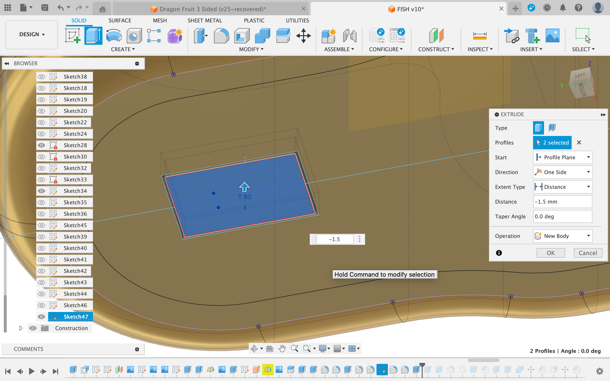
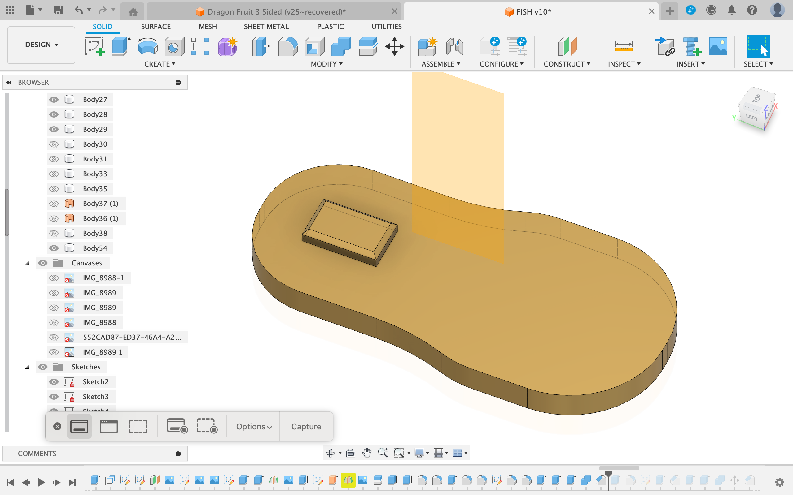
- Cut a 2 mm deep hole into the cover using the larger rectangle (the one you offset)
- Extrude the smaller rectangle into the cavity 1.5 mm (a bit less than 2mm)
- Extrude the large shape for the rubber foot out 2 ∼ 3 mm and make sure it combines with the rectangle extruded in the previous step but NOT the main castor wheel cover
- Chamfer the rectangular alignment pin
Sketching the Top Cover
- To create the top cover, start off by creating a sketch on the top face
- Project the outer contour of the top face
- Add two circles on either side and offset them 0.2 mm
- Create a line that just barely covers the area that encapsulates the wheel
Extruding the Top Cover

- Extrude-cut the larger small circles down 3 mm
- Extrude the smaller circles down 2.5 mm
- Extrude the entire front portion of the sketch up 3 mm and make sure it joins with the 2 smaller circles but NOT the main castor wheel cover
- Fillet the edges on the top face
- Chamfer the edge of the small pins
Slicing and Printing
Main castor Wheel
- Print as is
- Print in PLA/PETG/ABS
- Use 4 or more walls
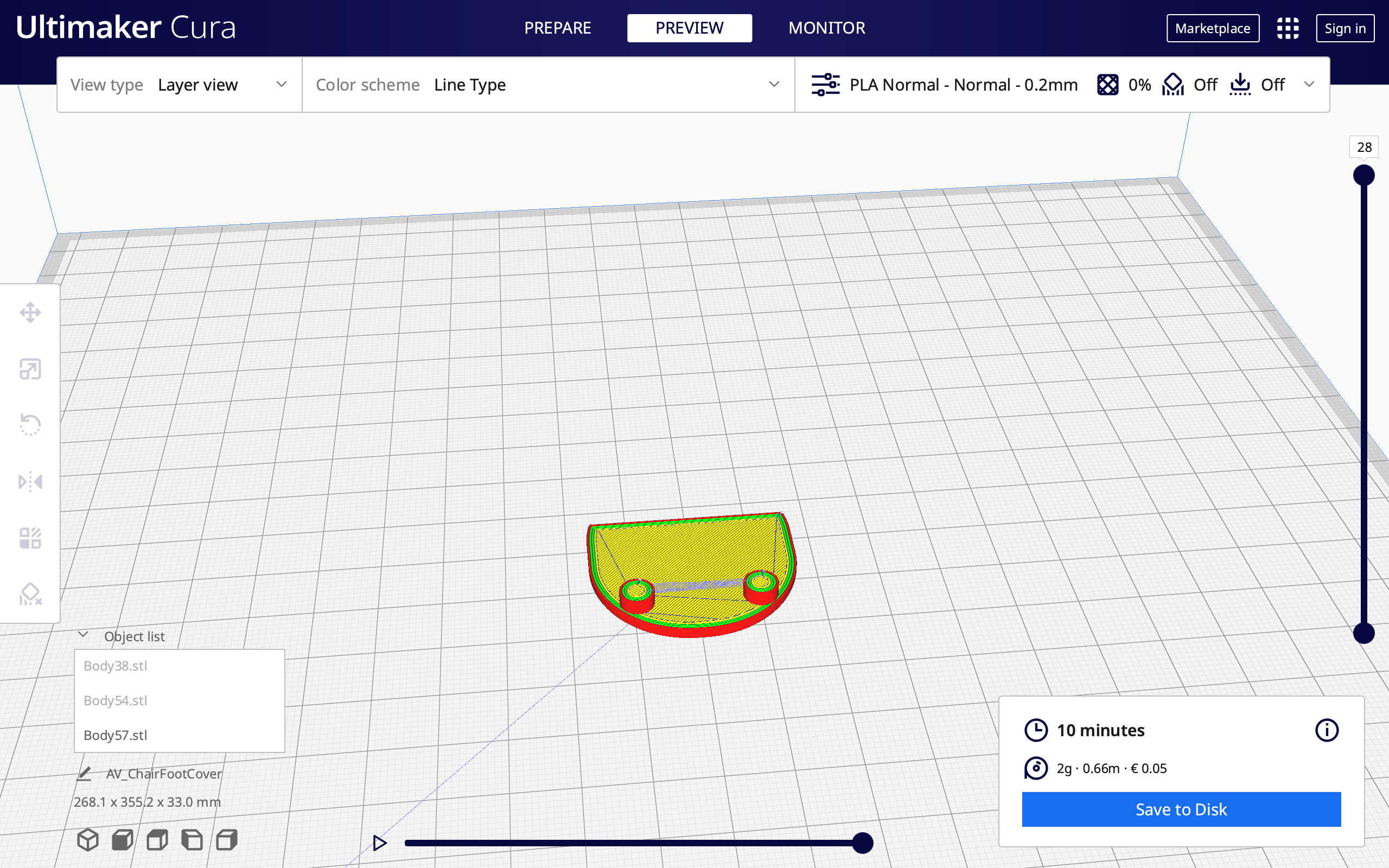
Bottom Rubber Foot
- Print as is
- Print in TPU
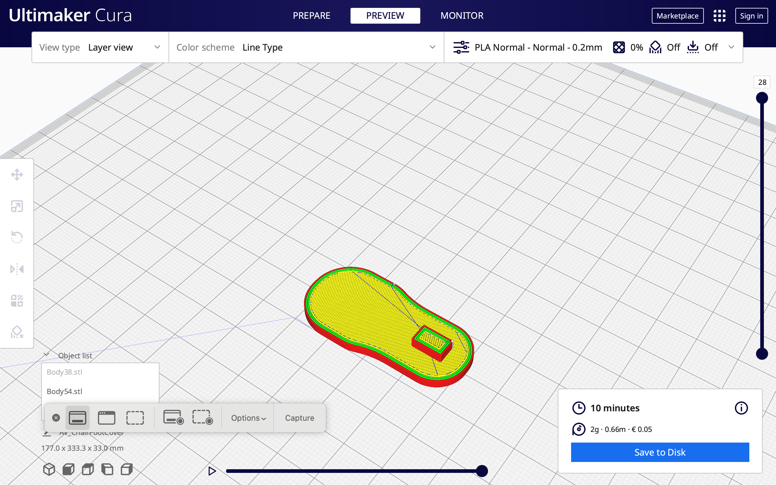
Top Cover
- Print rotated so that the pins face up
- Print in PLA/PETG/ABS
Assembly
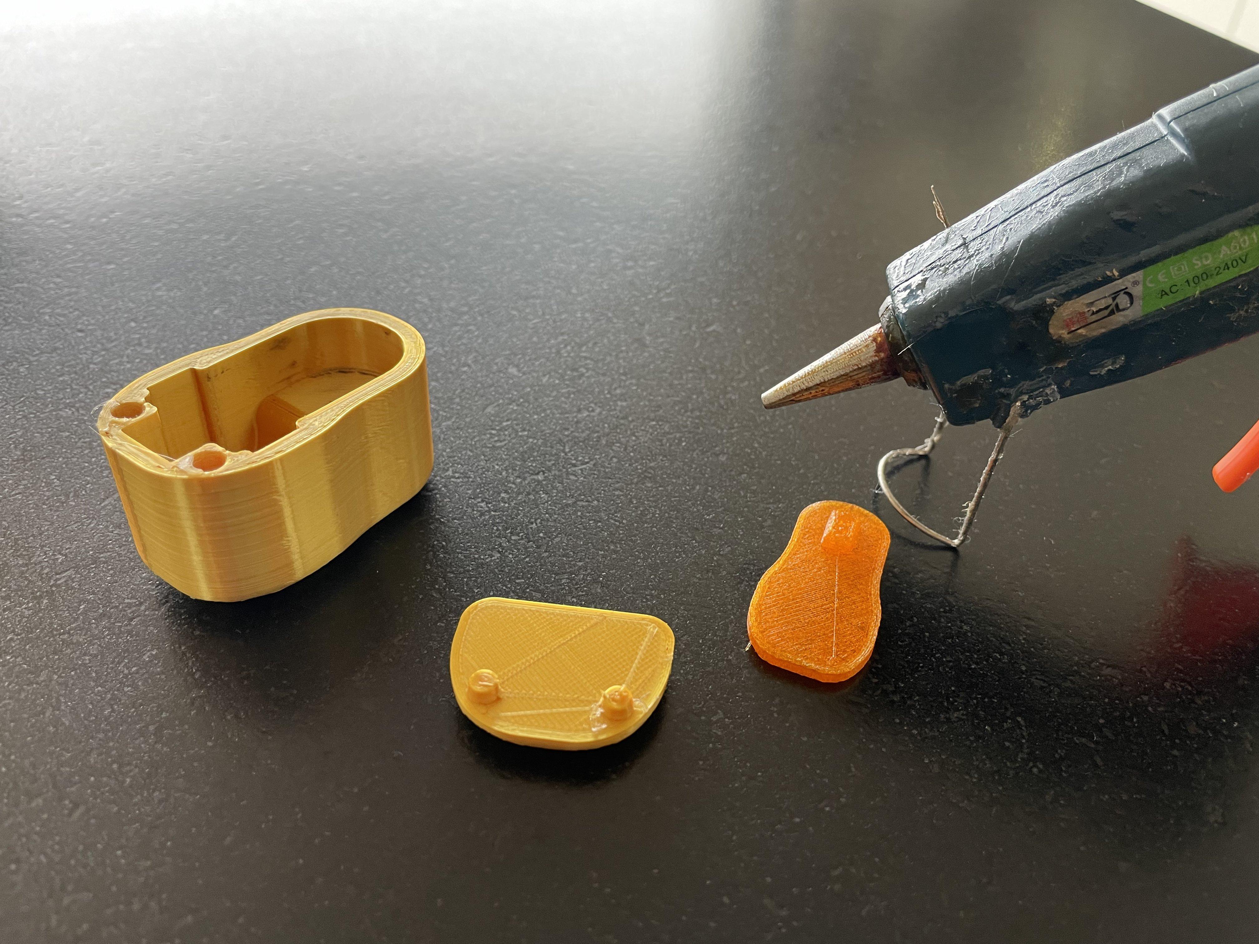
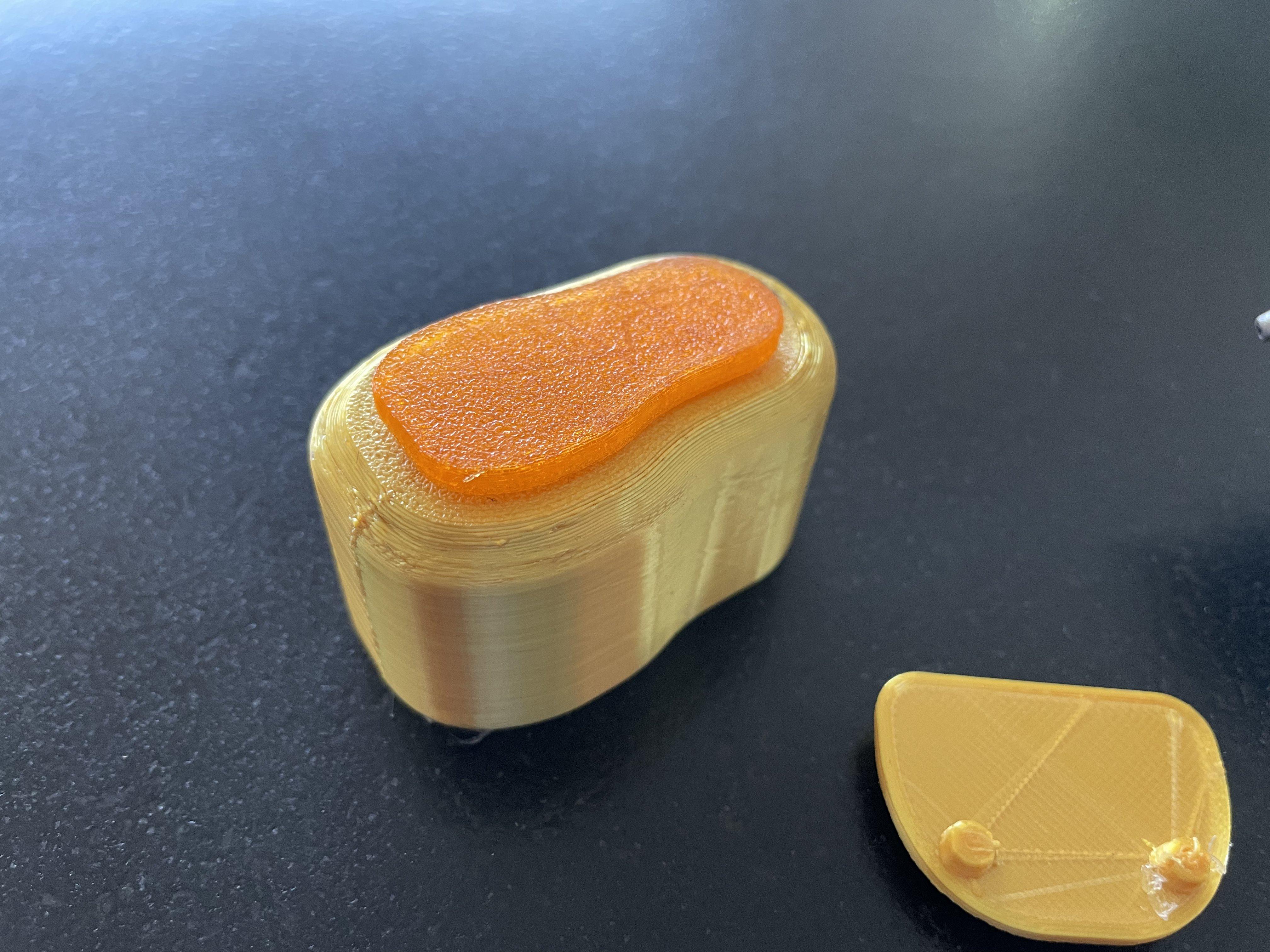
- Use hot glue to glue on the the Rubber Foot to the Main Castor Wheel Cover
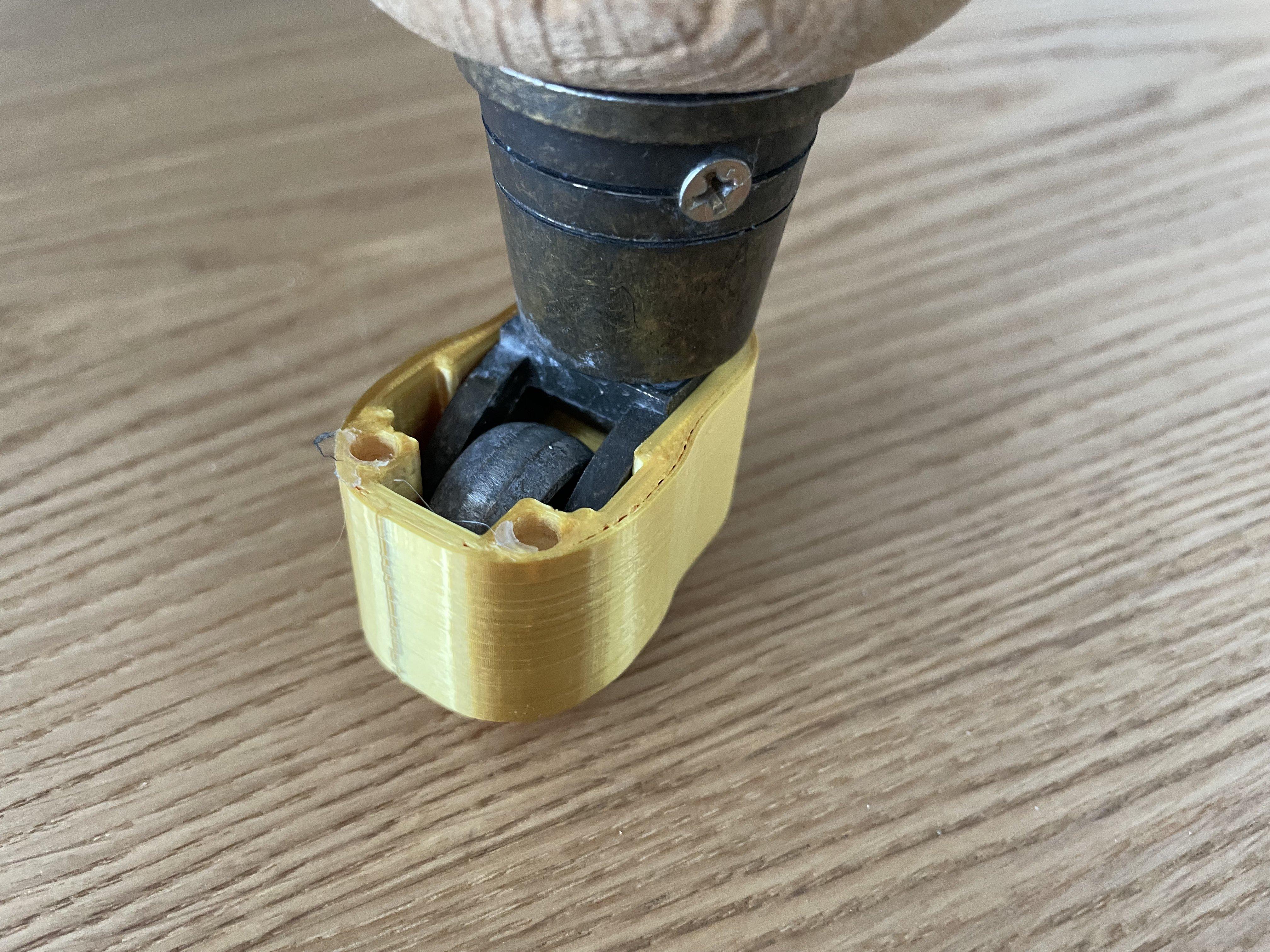
- Slide the Main Castor Wheel Cover onto the castor wheel
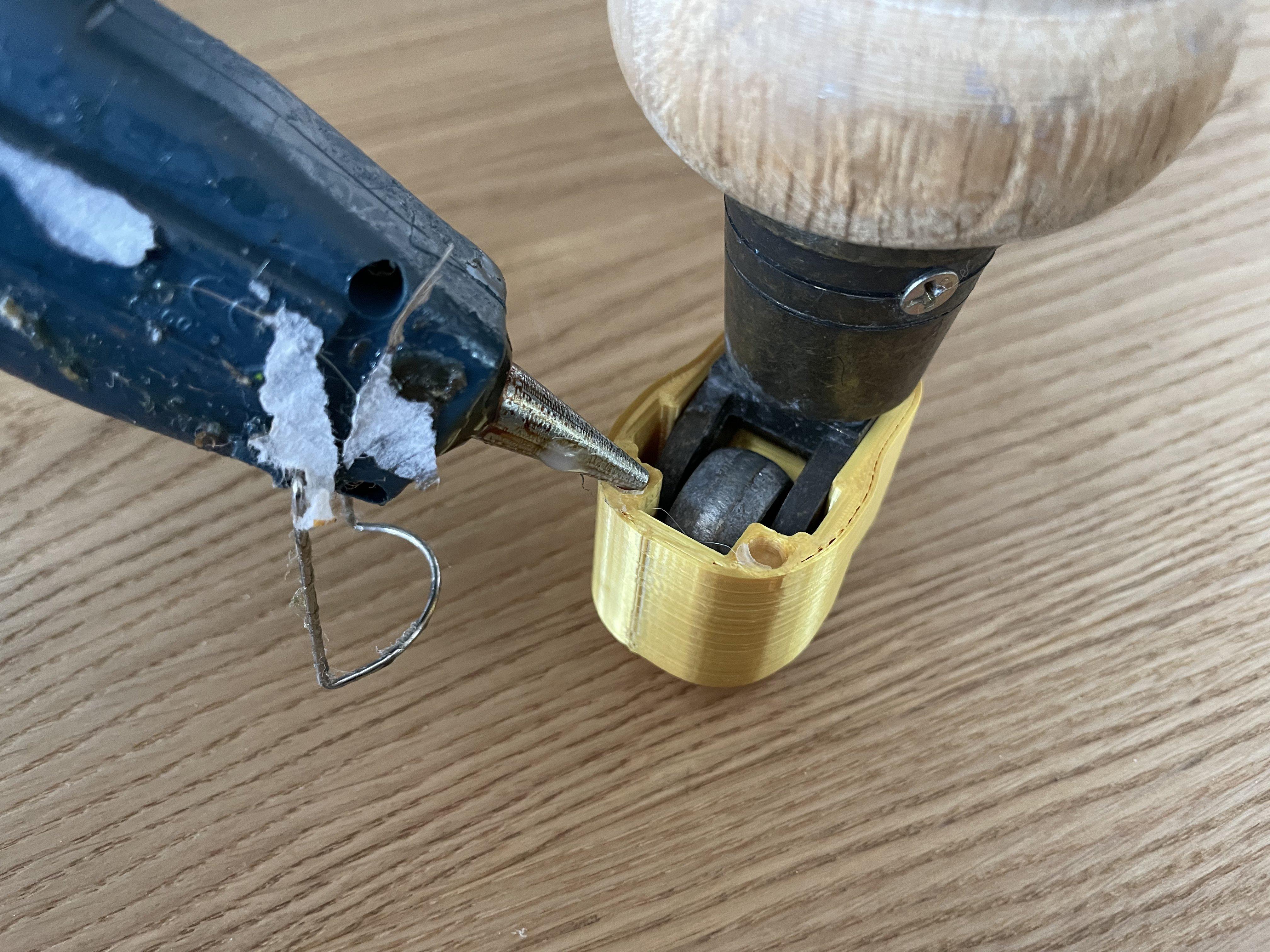
- Put a few drops of hot glue into the holes on the castor wheel top face
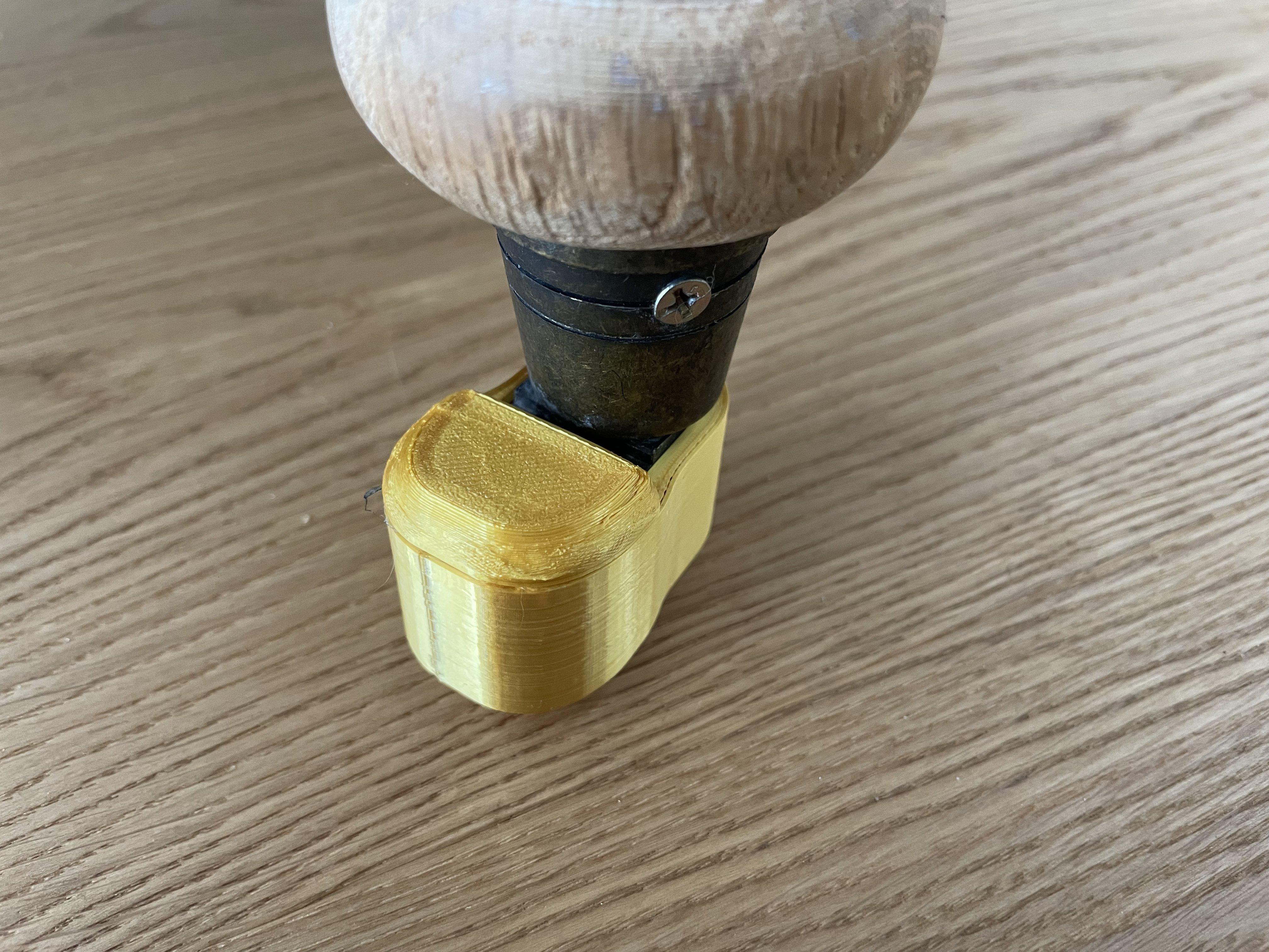
- Squeeze the top cover in place
Making Adjustments
If for some reason a part doesn't fit you can use the press pull feature in Fusion or adjust a sketch in the timeline
Done

