Create a WiFi Heat Map Using ESP8266 & Arduino
by Electropeak in Circuits > Arduino
2392 Views, 1 Favorites, 0 Comments
Create a WiFi Heat Map Using ESP8266 & Arduino
.gif)
Overview
In this tutorial, we are going to make a heat map of the surrounding Wi-Fi signals using Arduino and ESP8266.
What You Will Learn
- Introduction to WiFi signals
- How to detect specific signals with ESP8266
- Make a heat map using Arduino and TFT display
What Is WiFi?

Nowadays, many people use WiFi services on their smartphones, tablets, and PCs. WiFi is a protocol registered by the Wi-Fi Alliance to build the IEEE802.11 standard wireless LAN.
Wi-Fi is more powerful than Bluetooth. Wi-Fi is usually used to connect to the wireless internet, which has made this protocol much more popular. You can easily connect to the Internet anywhere, using this technology. The Wi-Fi standard supports a maximum speed of 11Mps at 2.4 GHz. To increase the speed of this standard, another version called IEEE802.11n was built which speed has increased up to 200Mps. This increase in speed is due to the use of the multi-channel antenna (MIMO), the use of two 2.4 GHz and 5 GHz frequency ranges, and Medium Access Control (MAC). The Wi-Fi board is about 20 meters.
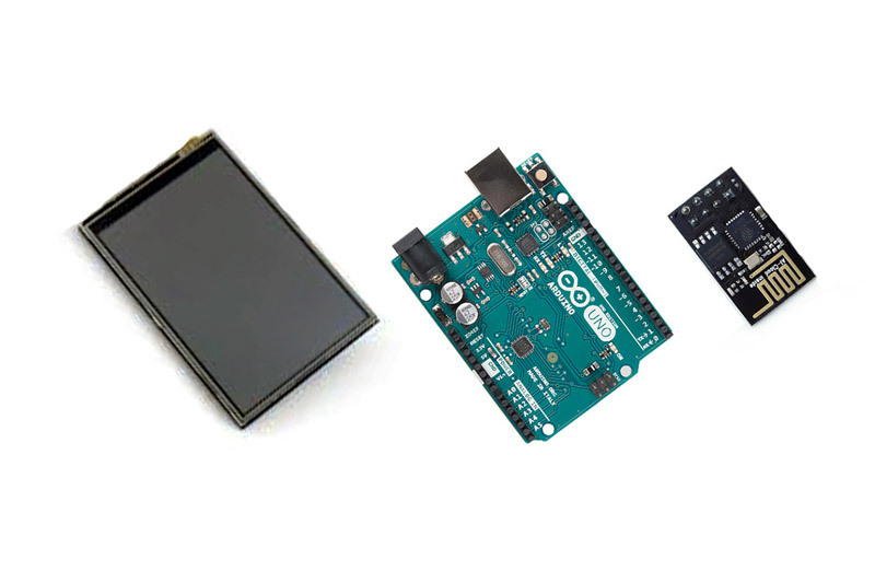
In this project, we want to create a WiFi heat map using the ESP8266, Arduino and 3.5″ TFT LCD. ESP8266 can detect the Wi-Fi signal of a specified SSID (RSSI). We used the ESP-01 module for this project. Put 4 of these modules in four corners of the room with a rectangular pattern. After receiving information from the ESP modules, we send them to Arduino to be analyzed and displayed.
What Is a Heat Map?
The heat map is a graphical data that gives the information in an attractive appearance. The heat map usually uses a color spectrum to analyze information, this color spectrum starts from warm colors and ends in cold colors. Each part of the map with the highest strength and coverage of the specific data (for example WiFi signal strength), has the hottest color, and so, with a decrease in the strength of the data, the color spectrum will approach the cold colors.
Required Materials

Create a WiFi Heat Map

Circuit
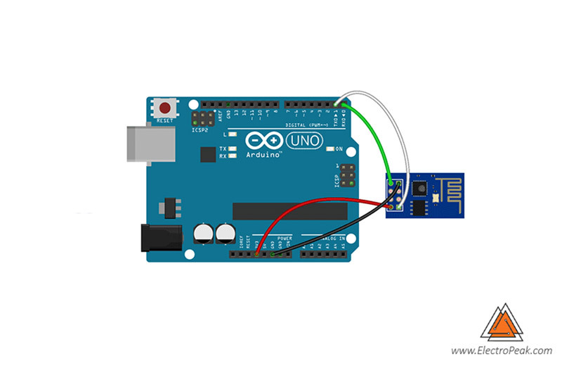
Connect the ESP modules to the Arduino board as it is shown in the picture.
After connecting the ESP modules, put the TFT Shield on the Arduino.
Code
First, we write a code for the ESP modules to check the signal strength and send it to Arduino. Then we write another code for Arduino to receive the information and display them.
Upload the Code 1 on each of your ESP modules. You can read this tutorial for more information about the ESP8266 module and how to upload the code through the Arduino IDE.
In this code, the character “1” indicates the ESP module identifier, for the subsequent modules, change this identifier. For example, for the second module, change the identifier to “2”. Enter your desired SSID name Instead of “specific SSID”.
Now upload the Code 2 on your Arduino.
In this code we used the Adafruit_GFX and MCUFRIEND_kbv libraries to display information on the LCD, which you can download from the following links.
After receiving the RSSI from all modules, Arduino calculates the strength of the WiFi signal according to the location. You can create your own colors by changing the r, g, and b variables.
What's Next?
- Try to analyze more SSIDs.
- Try to add more modules and analyze the 3D signal.