Create a 555 Timer Piano in Fusion Electronics
by rami_ in Circuits > Electronics
1414 Views, 11 Favorites, 0 Comments
Create a 555 Timer Piano in Fusion Electronics
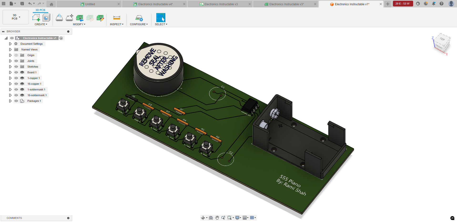
This Instructable will guide you in creating your first library, schematic, PCB and 3D Model for your new project! We'll be creating a simple electronic schematic which uses a 555 timer, buttons, capacitors, resistors and a speaker to create a small piano!
Here's our design process for this project.
- Create a library with our desired parts that we will source from an electronics website such as Digikey.
- Import the library components into a schematic and connect all components.
- Place components onto 2D PCB and connect traces on the board.
- Push to 3D PCB to generate a 3D model of our PCB!
By completing this instructable, you should have the basics of the entire electronics workflow in Fusion!
Supplies
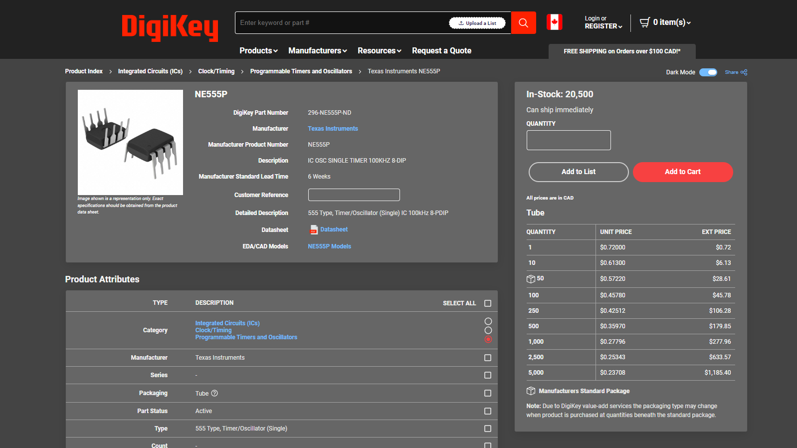
For this project, we'll be using off the shelf components from the online electronics part distributor, Digi-Key, as we want to learn the ability to import components and their 3D files from other websites. The following components are used.
- NE555P - 555 Timer - Link
- AST-03208MR-R - Speaker - Link
- Resistors (in default Fusion Libraries)
- Capacitors (in default Fusion Libraries)
- 1294 - 9V Battery Holder - Link
- TS02_66_60_BK_100_LCR_D - Switch - Link
All files are linked below with the appropriate Fusion Libraries
Prototyping With Tinkercad
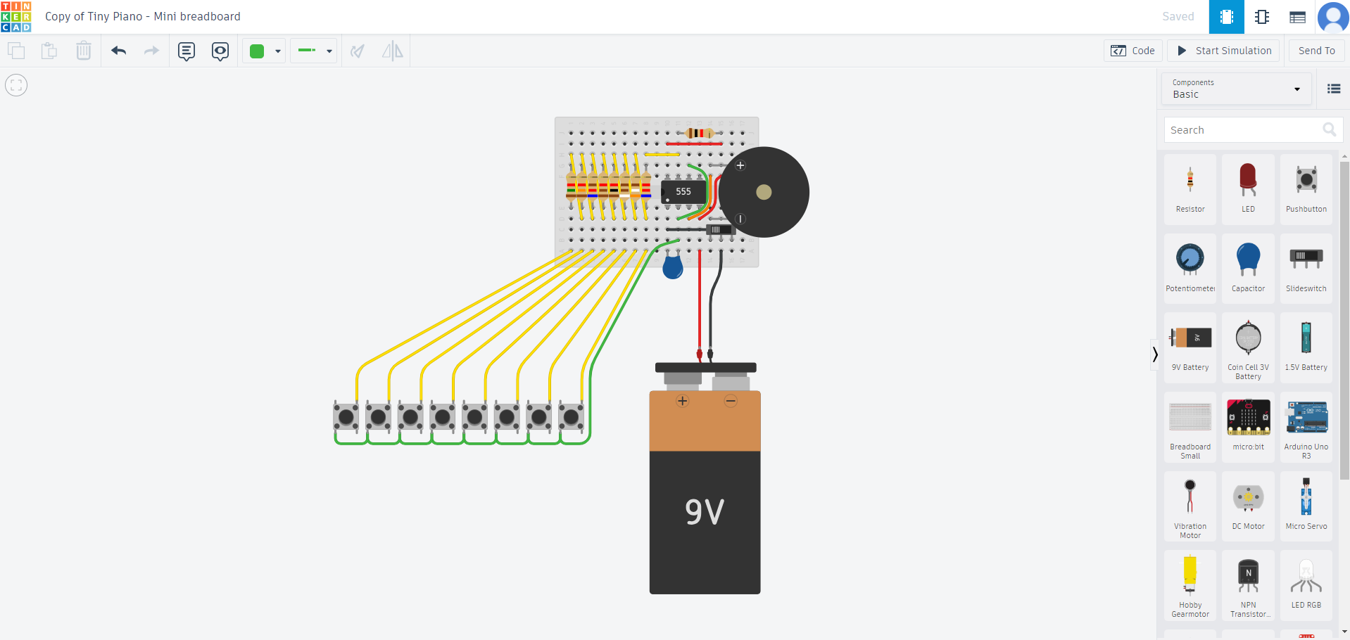
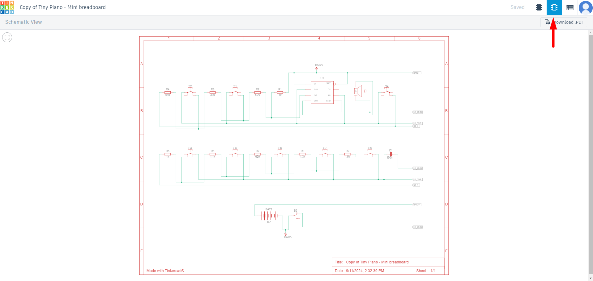
To get an idea or "tinker" with some physical components virtually before finalizing the components, Tinkercad is the perfect website for prototyping circuits and 3D designs right in your browser!
To start, Tinkercad has a large array of circuits that are available to explore in the Community Gallery, for example, this design by user "mr.punch" has the circuit we need, and allows you to remix the circuit and build upon it if you want to change certain things.
Tinkercad also allows you to directly create a schematic from the prototype made, this can be used to make the Fusion schematic much easier! While the tutorial doesn't necessarily use this schematic, this is a good way to get a schematic started in an easier fashion.
Create the Library for the Project
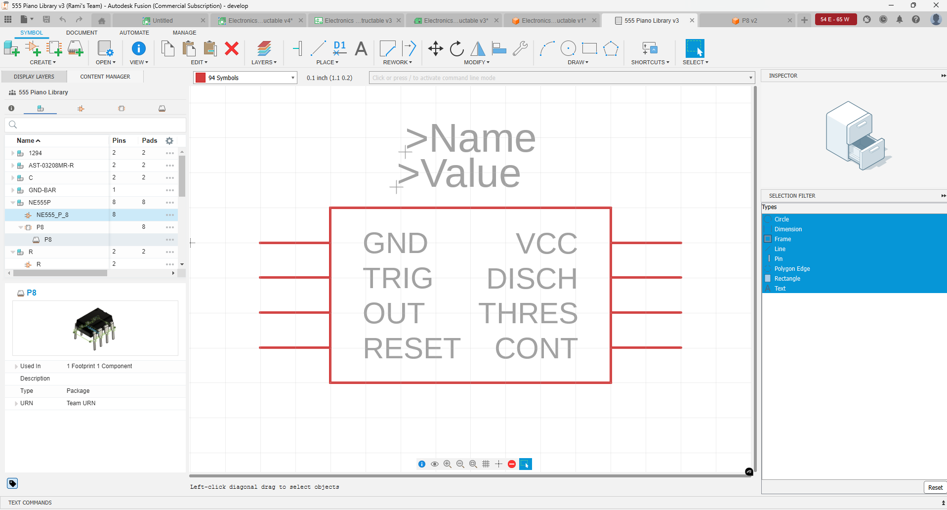
The first step in most Fusion projects is creating the library for the project. The library is a collection of components that we'll be using in the Fusion project, and each component is usually a collection of three items:
- The Symbol, which is what shows up in the schematic.
- The Footprint, which is the placement and pads of the part on the PCB itself.
- The Package, which is the 3D model that shows when a 3D PCB is created.
While it is generally recommended to create your own component to make sure it is accurate, in this instructable, we'll download components from an electronic components website.
For example, let's say we want to start a library called 555 Timer for the project and add the components, follow the following steps.
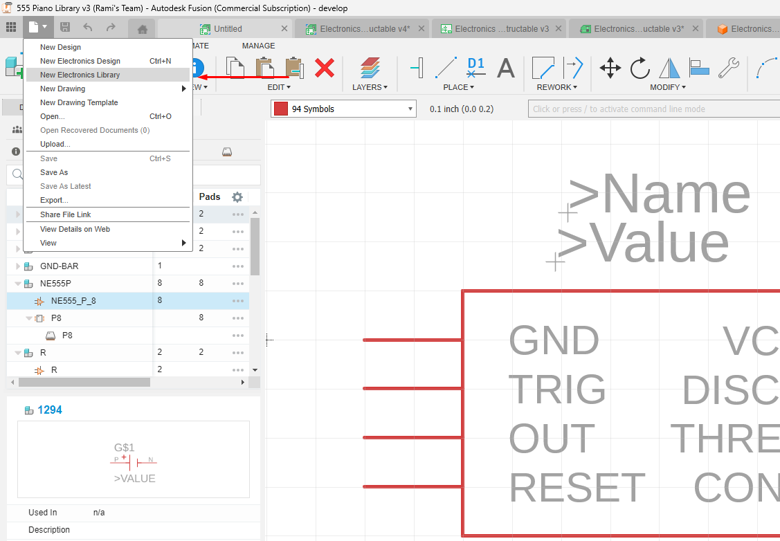
- Click on the File button > Create New Electronics Library
- Name it the project, "555 Timer"
Download and Add Components to Library
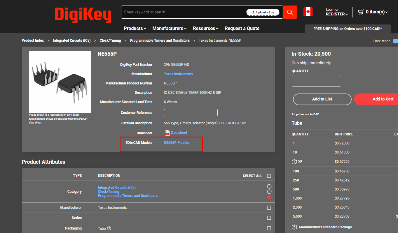
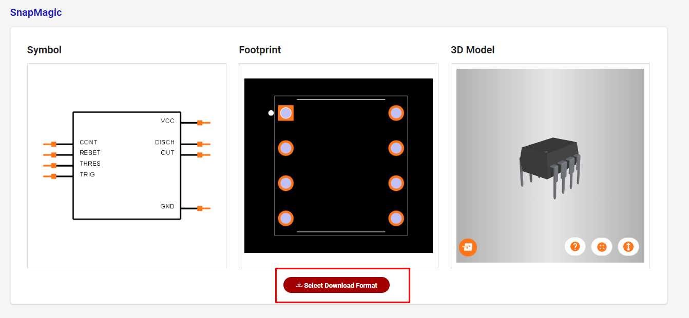
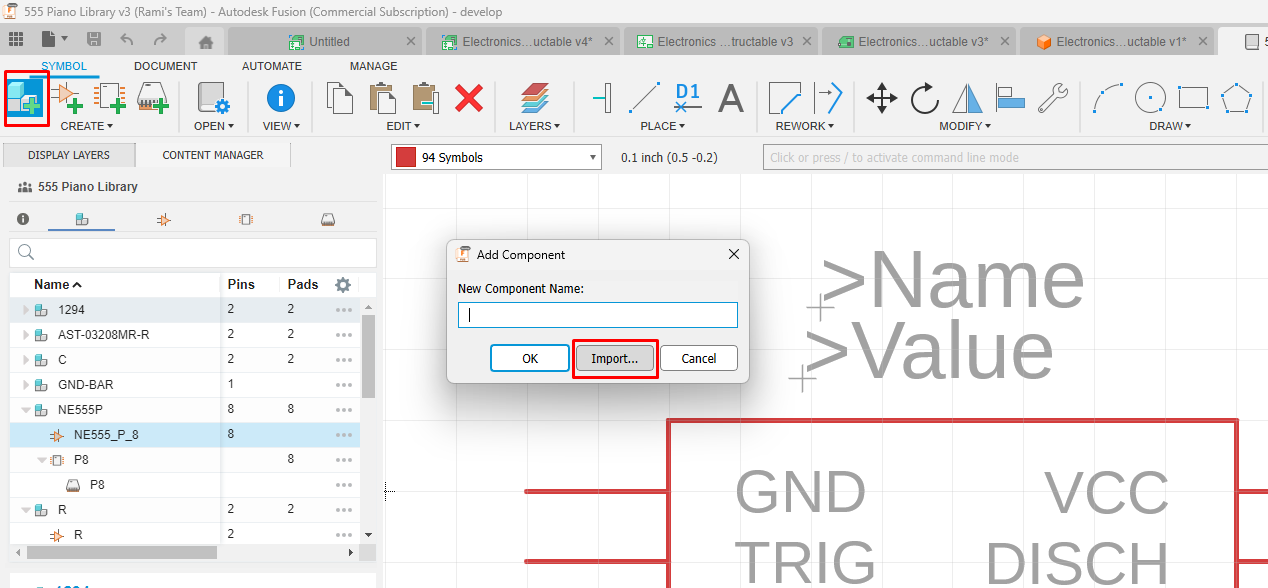
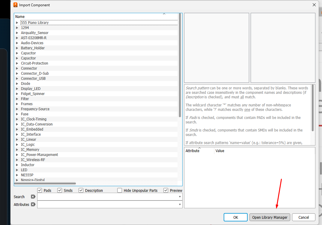
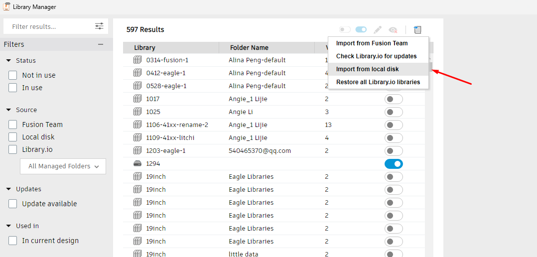
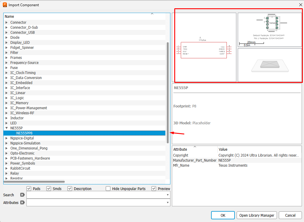
Most of the components we'll be adding will be downloaded from the Digi-Key websites, on most product pages you can follow the following steps.
Select the option to download the EDA files, and download the Fusion Library file (.lbr) as well as the 3D model (.step) file from the website.
Once the files have been downloaded, follow these steps
- Create a new component by selecting the "New Component" button in the new library.
- Open the Library Manager in the "Import Component" window.
- Select the import libraries button and select from the local disk.
- Upload to Fusion.
- Select the part from the "Import Component" window.
- Repeat for each component.
Files are provided in the instructable for this particular sketch.
Add .STEP Files to All Packages
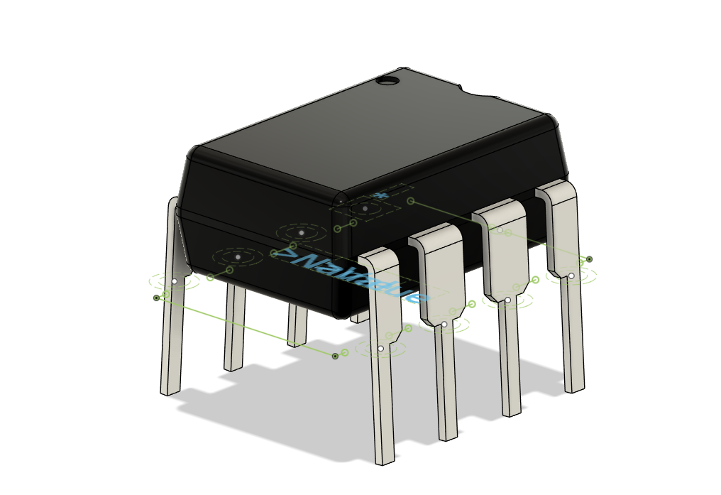
Follow these steps:
- Upload the 3D CAD model to the Fusion cloud.
- Open the library.
- Go to the Footprints.
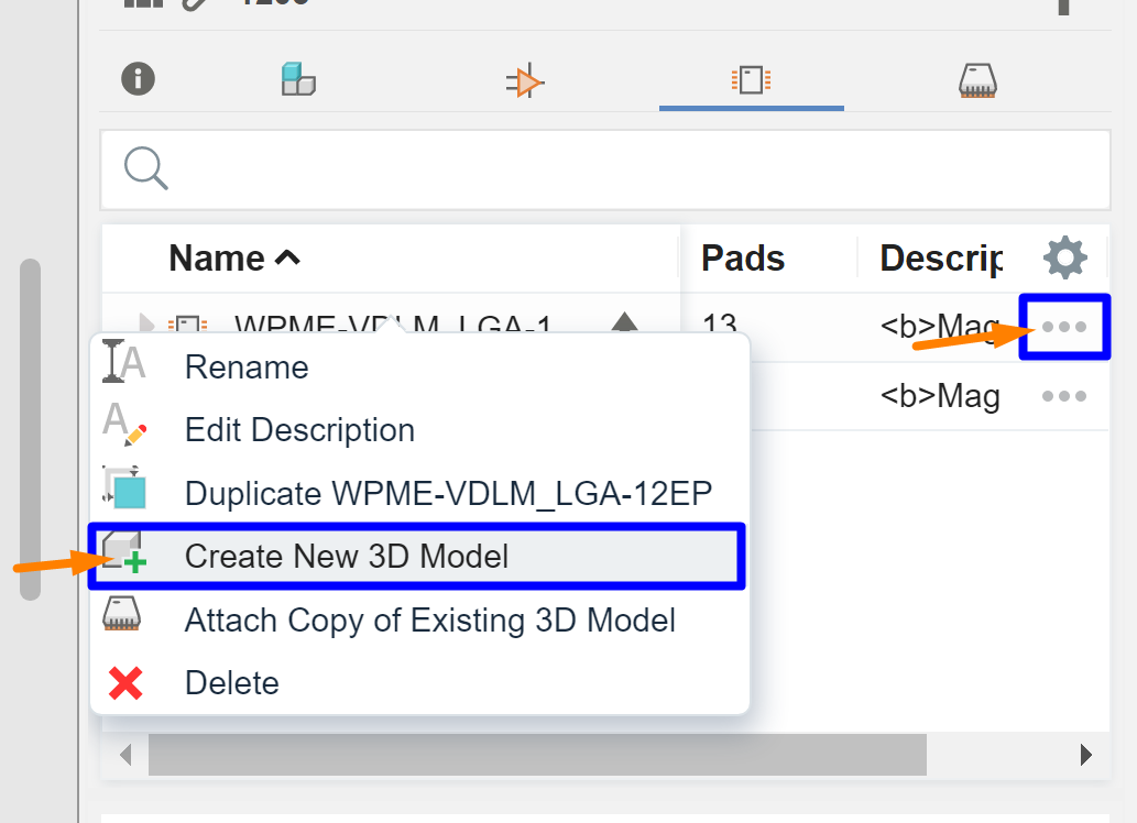
- Click three dots near the particular footprint -> Create new 3D model.
- Save it.
- In the Data Panel right-click on the 3D CAD file -> Insert into the current design.
- Move/rotate the model if needed.
- Click Finish and Save.
- Save the library.
Create the Schematic
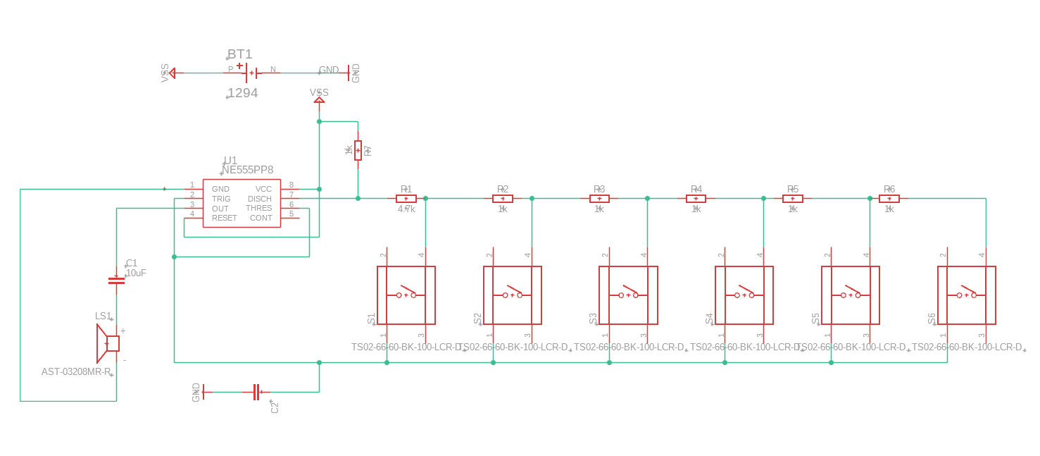
For this piano, the attached fusion schematic can be used. To create this manually however, it's as easy as opening the library in the schematic file, moving all the components in the library. Connect nets to each component and once finished, you can push these changes to the 2D PCB.
Note: This schematic design is mostly inspired by the schematic provided on the tutorial at https://elonics.org/electric-piano-circuit-using-555-ic/, please refer to the Eleonics website for further information on the schematic.
Downloads
Create the 2D PCB
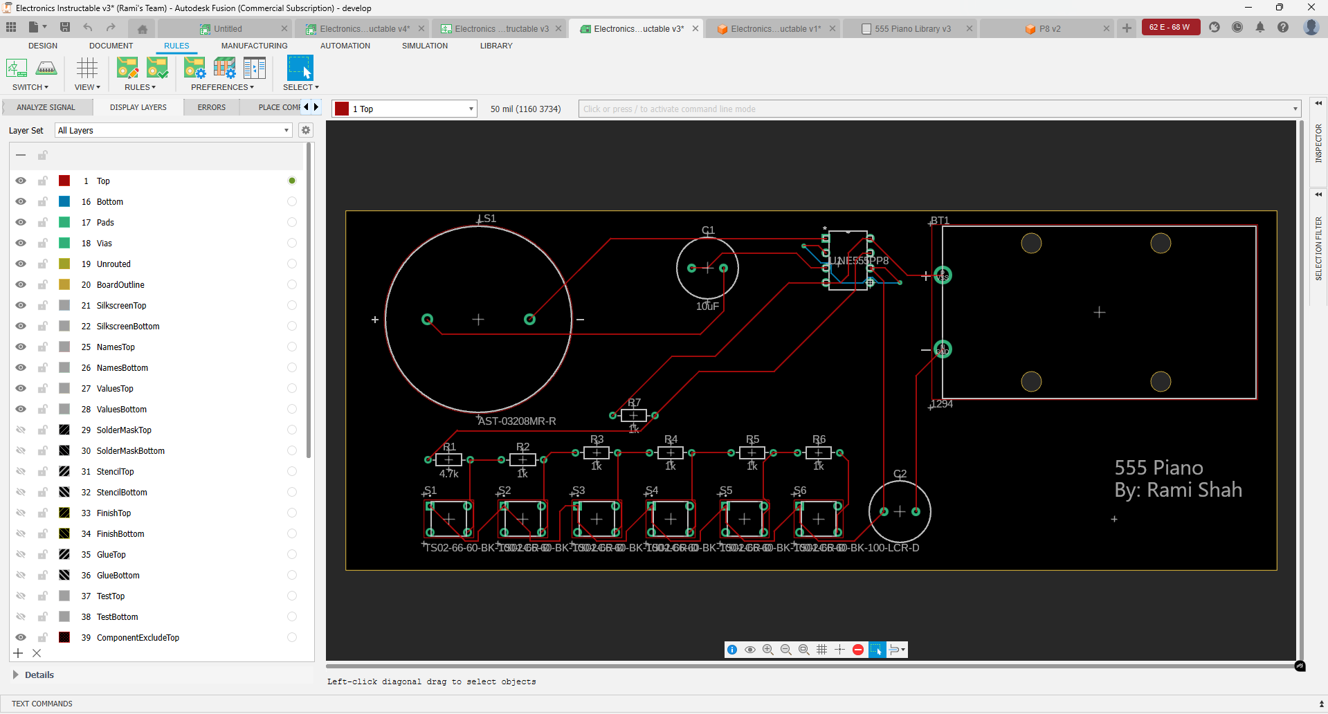
Once the schematic has been pushed into the 2D PCB, all of the components will be populated with airwires already shown for what the connections are.
Creating the PCB is as easy as moving the components around, and adding traces for the PCB.
Use the middle mouse button to create a via that switches from the top layer to the bottom layer.
Push to 3D PCB to finally finish the component and see the final result of your PCB!
