Converting Eachine Racer 250 to ArduPilot (APM 2.8)
by EpiDrone in Circuits > Remote Control
6770 Views, 34 Favorites, 0 Comments
Converting Eachine Racer 250 to ArduPilot (APM 2.8)
Here is my first Instructables explaining how I converted the Eachine Racer 250 quad to use the ArduPilot Copter flight controller (APM to keep it short). For me it was a perfect start to get familiar with quadcopter components, setting up a flight controller, radio configuration and tuning without breaking the bank.
After a few days waiting I received my Eachine Racer 250. A very well built mini-quad that flies very good out-of-the box. I only made two short flights before I decided to convert it into a fully featured mini-quad with FPV (first-person-view-video), GPS and a flight controller that could be used for automated flights.
I ordered the Eachine Racer 250 RTF package from banggood with monitor because I wanted both a remote and a monitor and liked that it was ready-to-fly (RTF).
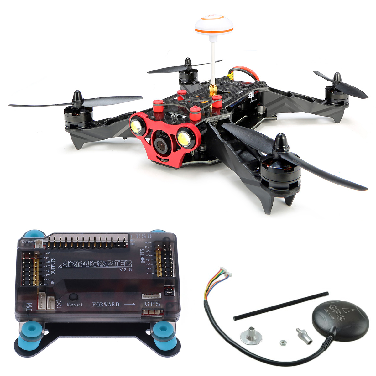
For the flight controller you could also go with a more expensive Pixhawk or clone but APM is a good start for beginners. I bought a set with ArduPilot/APM 2.8, 6H GPS and 915Mhz Telemetry for $85. The radio telemetry saves a lot of time if you plan to use Mission Planner/APM Planner 2/MavProxy to automate the quadcopter.
For tools I didn't need more than a 2mm hex screwdriver and a few zip-ties. (I borrowed a soldering iron and glue gun but managed to make the conversion without using them)
Useful links:
APM Flight Controller Set APM 2.8 6M/H GPS
Disassemble the Machine
Unscrew the top deck and collect screws and carbon fiber stuff falling off the arms.
Disconnect the cables from the old flight controller, mine came with a CC3D with 4 screws and was easy to remove.
Remove the black cable-bridge from the Radio receiver (Eachine iA6) strapped on the side of the main board.
Tip: I mounted two of the stand-offs from the old flight controller just to keep the battery from sliding forward.
Connect Motors to APM
I started by plugging in the APM to a computer, installed Quadcopter firmware using APM Planner 2 and did the basic setup (checking GPS, gyro and radio).
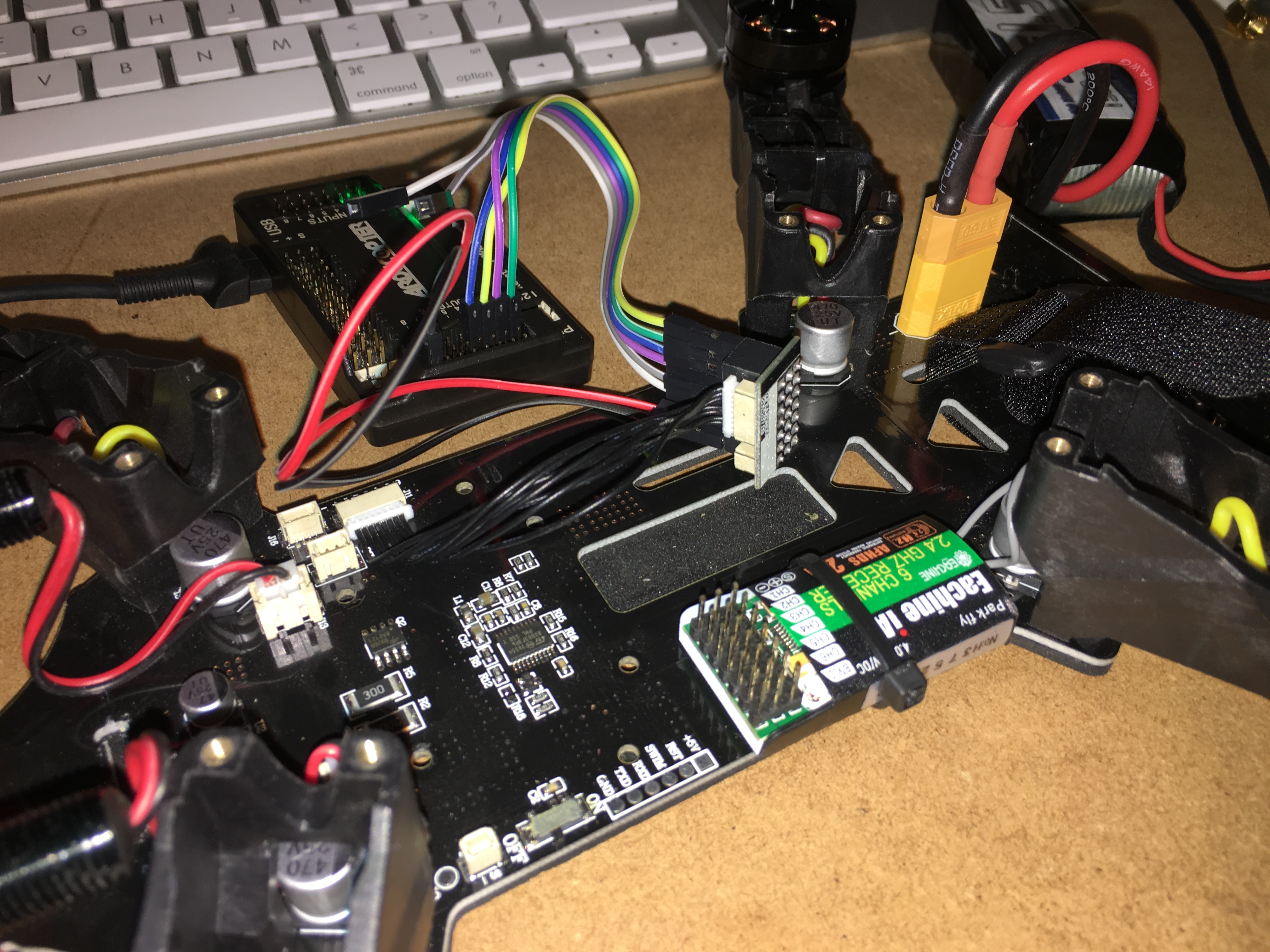
To power the APM I learned from another quad project that if the J1 jumper is connected you can throw in power anywhere on the input/output connectors to power it up.
To avoid soldering or buying extra cables I just took the old radio bridge to mini-8-pin connector. Connect this to the power board (base) where its marked J11. See photo and you'll see the little black thing connecting APM to the small 8-pin plug on the power-board.
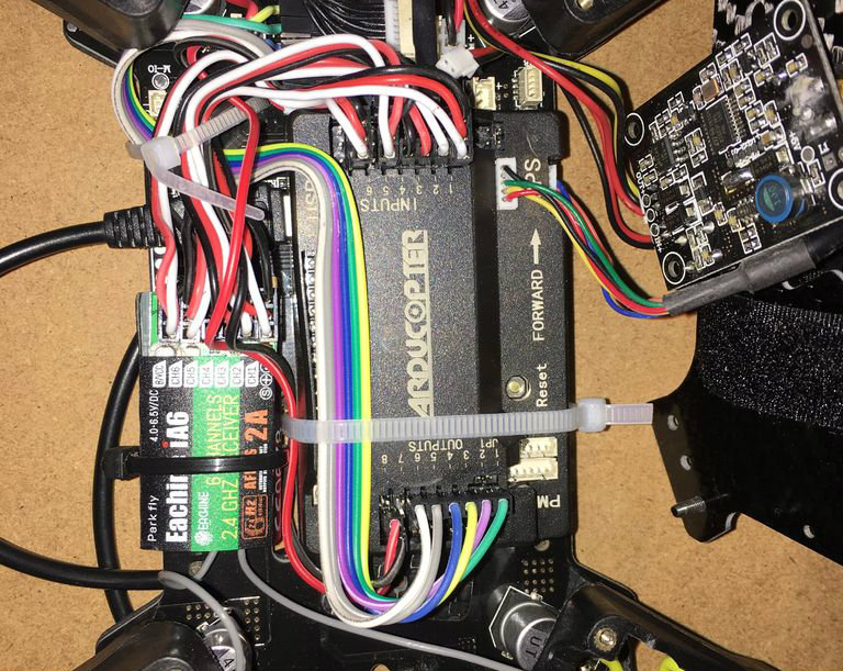
Connect black/red wire for 5v power from any of the pin-rows on the bridge to your APM output. I put them at the last row on both just to make some space for the other cables. If you have the bridge facing towards you with mini-8-pin connector at the bottom the top-right-pin is signal for motor 1. Pins are from top (S + -) so red goes to second pin on the right. I used some Male-to-female Arduino cables to connect the motors to APM.
Important note is that the motors should not be connected 1-1, 2-2 and so on. To get the correct x-quadcopter setup you must connect:
- motor 1 (yellow) to APM output 3
- motor 2 (green) to APM output 1
- motor 3 (blue) to APM output 4
- motor 4 (purple) to APM output 2
I connected the other two outputs (5,6) to Output 5,6 on APM but have no idea what these are used for.
Connect IA6 Receiver to APM
I used a few servo-cables (white, red, black) to connect the radio receiver to APM. For receiver channel 1 use all three connectors (white facing the receiver label). This give power to the receiver. Then I used second cable to connect channel 2,3,4. Add additional signal cables for channel 5,6 and connect them to APM input 5,6.
Tip: When I unpacked my drone the receiver was not bound to the i6 transmitter so i followed this video to bind it.
Tip: I later changed RC channel 6 to APM channel 7 since it was easier to program mode to this in APM. I used this switch to trigger RTL (return-to-land).
Mount the APM and GPS
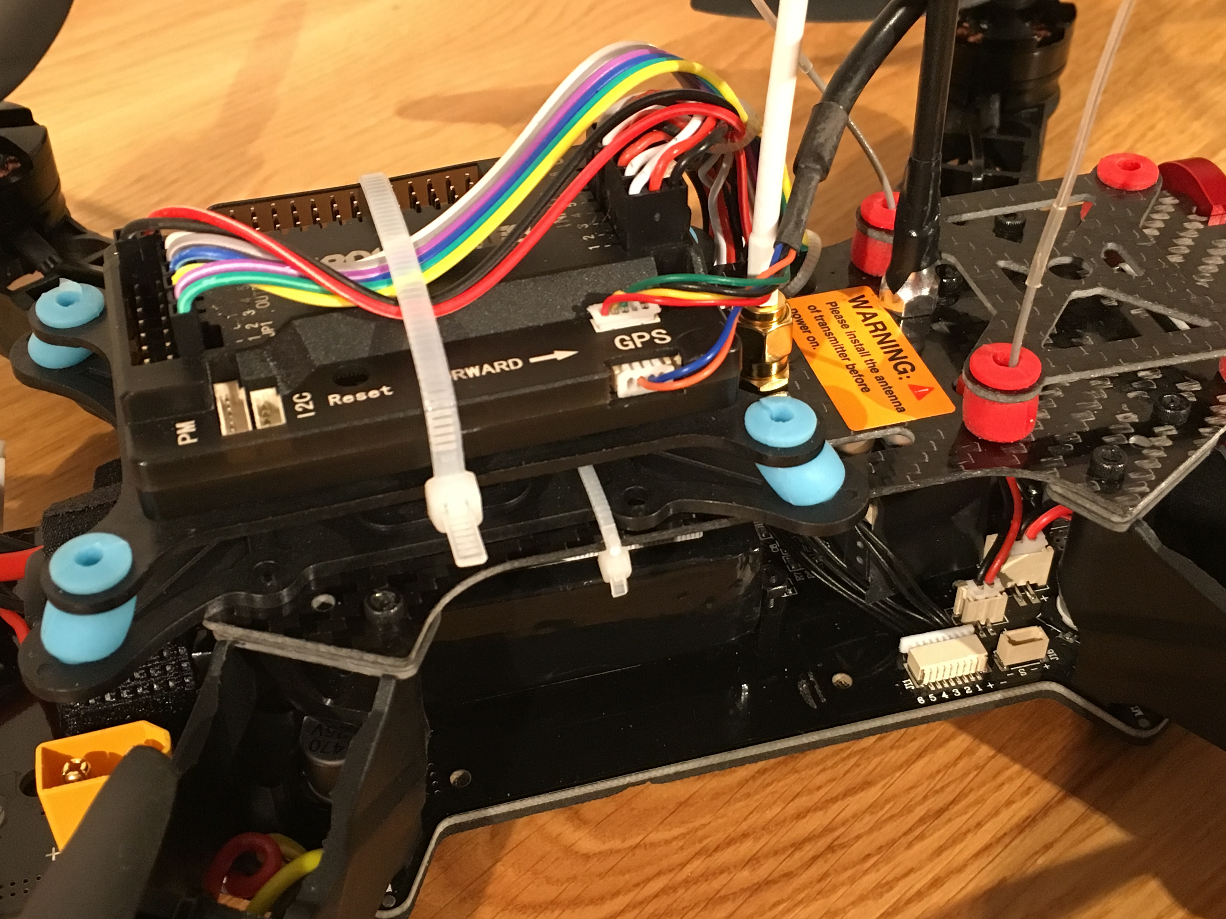
I connected the GPS to the APM using the two included cables in the kit and mounted the antenna holder in the little hole behind the GoPro mount on the top deck.
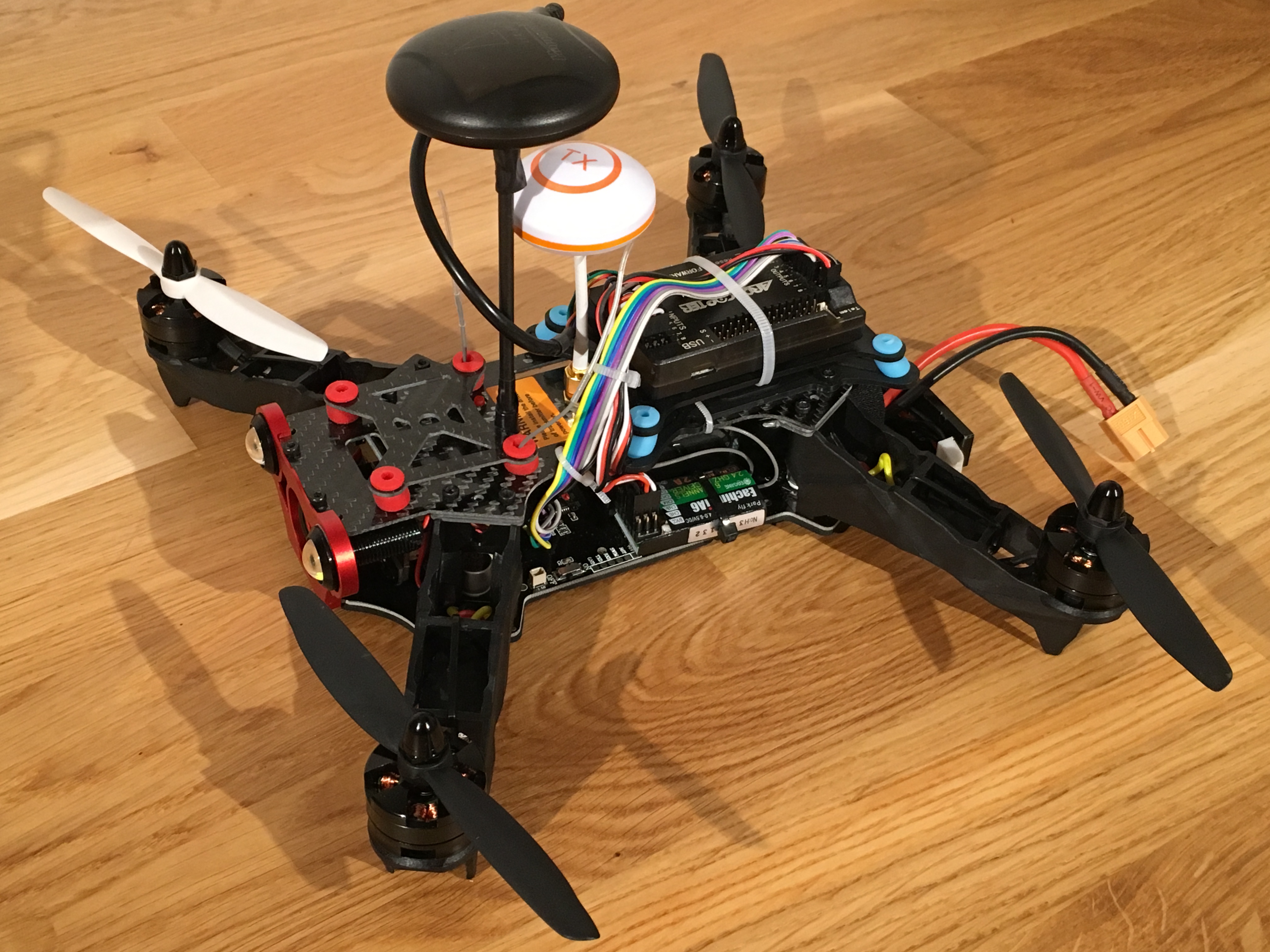
I used the vibration damping plate that came with the APM kit and zip-tied it to the top deck behind the video antenna (white mushroom). From the beginning I tried to mount the APM directly on the base-plate because it looked very tidy hiding all cables inside. After a quick test-flight this was way too much vibrations and the quad was flying terrible. On my second attempt I placed it on the top deck which made great space for the Lipo battery on the base plate. Let me know if you've found nicer ways to mount it or got it to work without vibration damper.
Add the velcro at the back to hold the battery, use a few zip-ties to tidy up the cables and your good to go.
Tip: Push the APM forward as much as possible so you get space on the back to plugin the battery connector.
Tip: The video transmitter under the top deck gets very hot so keep cables away from this to avoid melting.
Setup Firmware, ESCs and Test-fly
Connect a mini-USB cable to the APM from a computer and set up firmware and parameters using the wizard or configure manually (quadcopter, x-style, calibrate accelerator, compass and radio).
Warnings: Always remove propellers before ESC (Electronic Speed Controller) calibration, testing radio or tuning motors. I learned the hard way that even these little propellers can make a pretty deep cut in the arm. Start your test-flight slowly and controlled on short grass. Also setup failsafe mode before flying.
Tip: At first I used APM Planner 2 on my Macbook to set it up but felt that many important settings were missing from Mission Planner for Windows. I had no old PC available and needed a field monitor/programmer so went out to buy a TrekStor SurfTab wintron 7. Quite slow Windows 10 tablet but it is more than enough to run Mission Planner and for $65 (on sale) it was above expectations. It has a short host-USB-cable which is perfect to plugin the radio telemetry usb dongle.
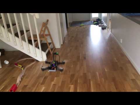
Tip: I didn't recalibrate the ESCs after connecting the APM and the first test-flight was very wobbly. On higher thrust it was literally shaking off components. I did a quick ESC calibration by taking off propellers, plugin battery with thrust at max, disconnecting battery and reconnect it with thrust still at top. Wait for some beeping and a pause, pull thrust to bottom, wait a little more for the startup-sequence tone and try out the motors by adding some thrust. After calibrating the ESC it was flying surprisingly good in stabilize mode using default parameters (see video for an indoor test-flight).
Tip: I recommend using 3DR Radio Telemetry kit when you configure and test-fly the drones since its very convenient to update parameters and show data on-the-fly. I ordered both 433 Mhz and 915 Mhz 100mw modules and for some reason my 433 Mhz was much more stable, but that could also be a setting.
Troubleshooting
I got stuck a few times on the way and give you some advice on what could go wrong.
Quad rotating and turning wrong direction when flying
On my first test-flight I connected the motors wrong so when flying and pitching/rolling it went in the wrong directions. Check the motor connections at my previous step.
APM not detected by computer
If your APM isn't detected by the computer, try switching USB cable. I had to go through 3 cables before it detected mine. Supposed to be something about some cables only providing power and some have data.
3DR Radio telemetry not connecting/working
My 915 Mhz kit came with the telemetry-cable wrongly wired so had to rewire it. Easily done using a little knife/nail and stable hand. Correct pins for radio transmitter: GND/5v/RX/TX (black, red, green, yellow on 4-pin connector) and on APM telemetry port: red, green, yellow, (empty) black on a 5-pin connector.
Quad is flying very un-even, wobbling or rotating
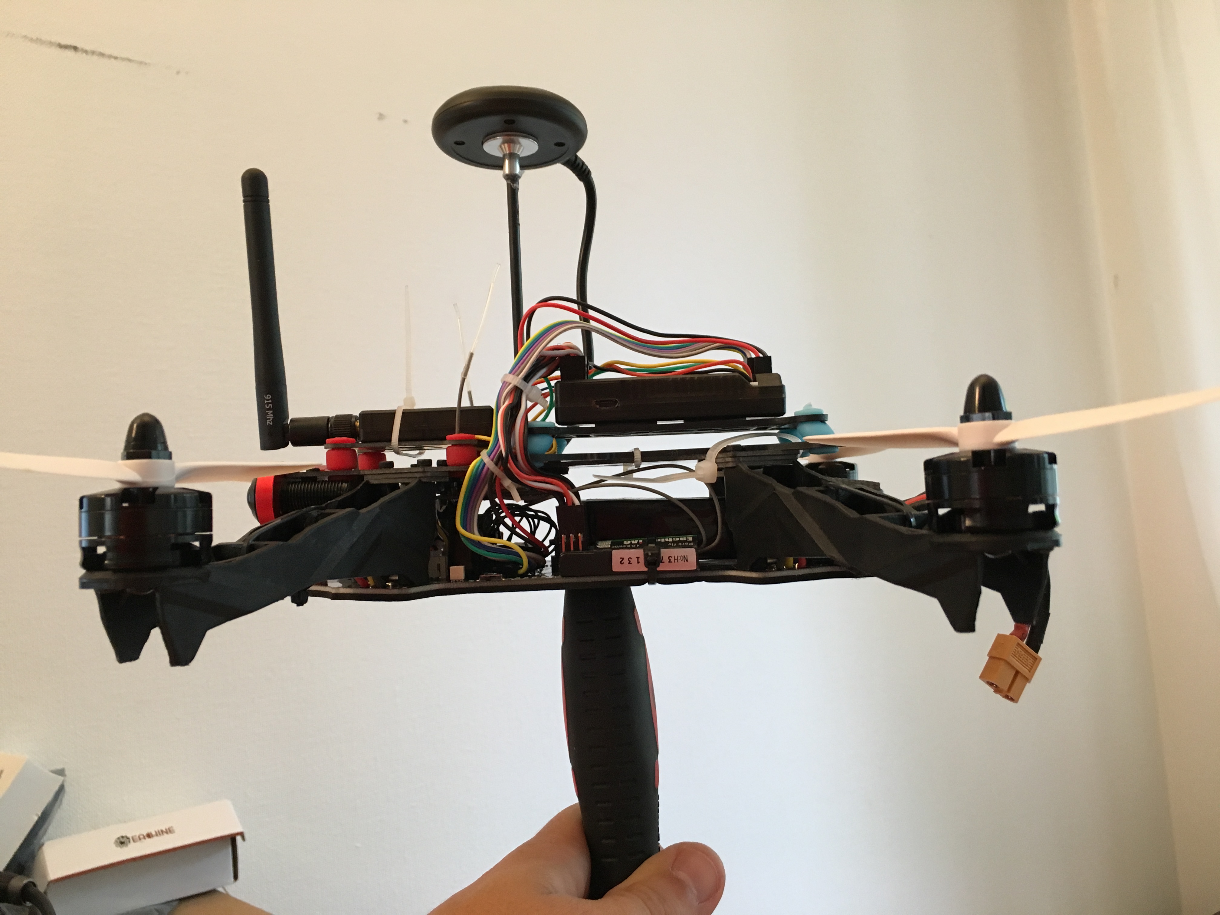
Start with a proper ESC calibration. I still haven't figured out exactly how to do this but there are a lot of videos on youtube. Calibrate the accelerator on a flat surface. Check center of gravity (COG) holding the quadcopter with two fingers or put it on a screwdriver. In the picture you can see that after some moving of battery and component it should balance in the center without holding.