Controlling Light Bulb in Your Room Using MC-38 Wired Magnetic Door Sensor
by Rucksikaa_R in Circuits > Arduino
2433 Views, 3 Favorites, 0 Comments
Controlling Light Bulb in Your Room Using MC-38 Wired Magnetic Door Sensor
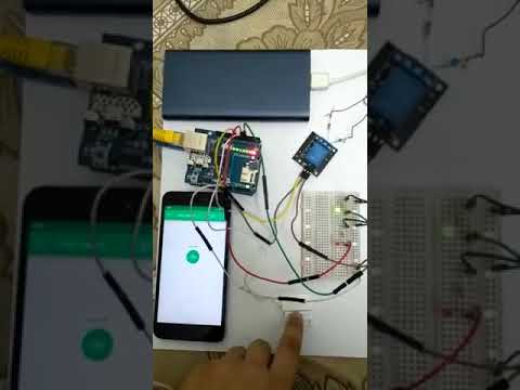
This is my first IoT project and I have made a prototype. Arduino Uno R3 and MC-38 Wired Magnetic Door Sensor are the main components and I am using Blynk application by Blynk.Inc to arm/disarm the sensor.
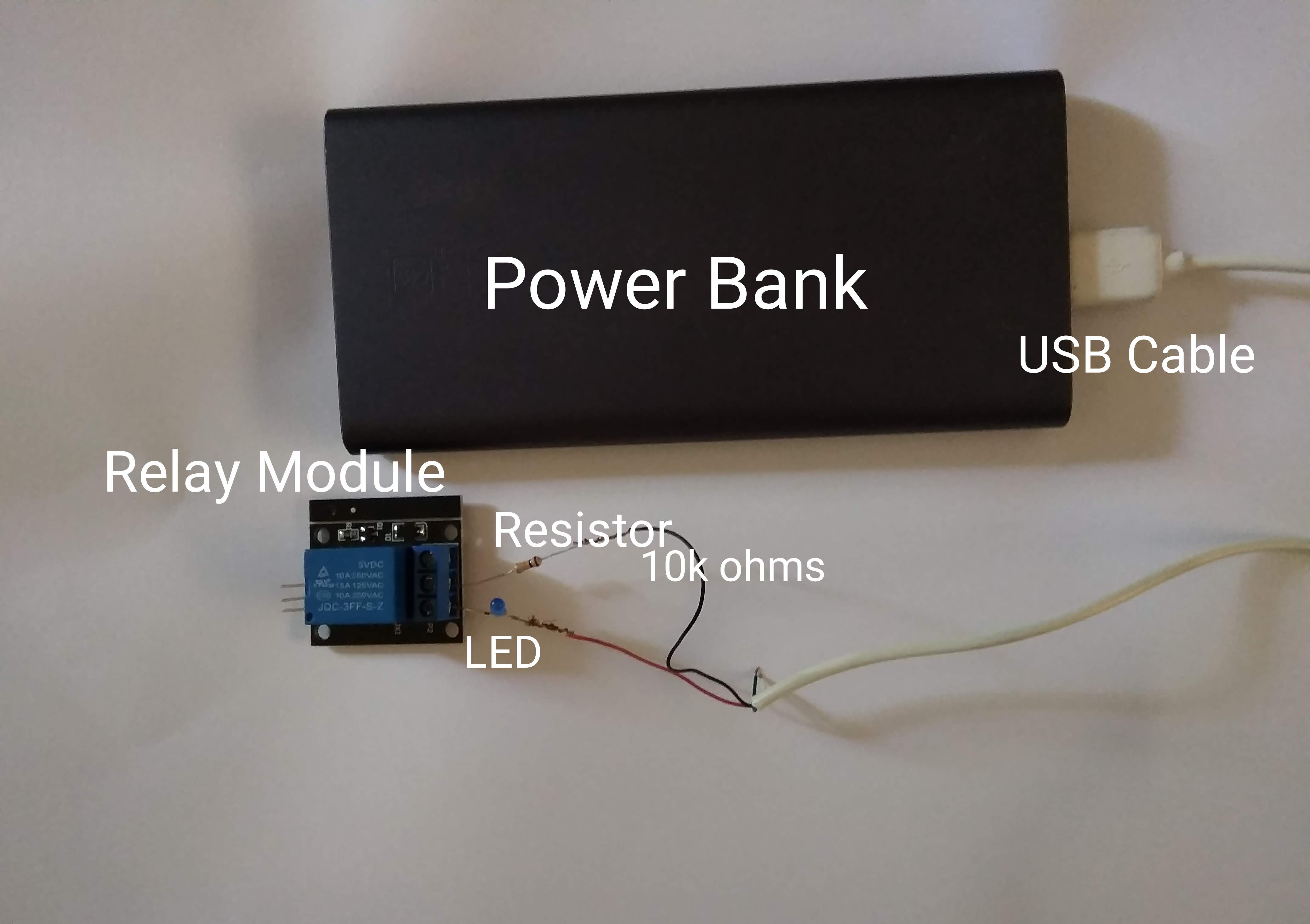
As this is my first project, I did not use mains electricity to connect with my relay module. Instead I used my power bank and LED to represent mains electricity supply and the electric bulb.
When you execute this project for longer term usage, connect the Arduino Uno R3 to a 20000mAh power bank and when not in use, remove the power bank and recharge it.
Supplies
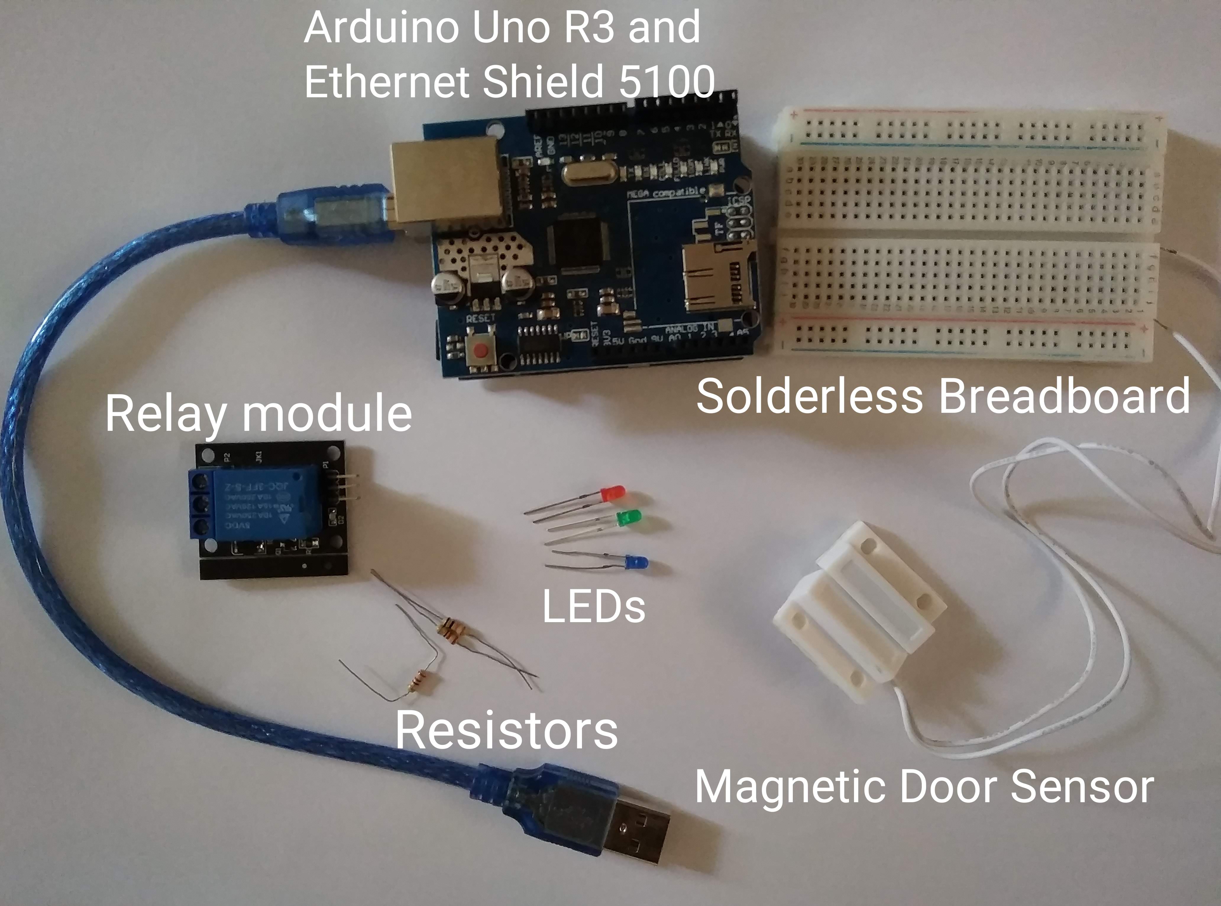
You will need:
Hardware
- Arduino Uno R3
- Ethernet Shield 5100
- MC-38 Wired Magnetic Door sensor
- Relay module - 5V (1 channel)
- Light Emitting Diodes (LEDs) - 03 (Green, Red and Any other colour you like)
- Resistors - 03 (one 10kΩ and two 220Ω)
- Solderless Breadboard
- Jumper cables (3 male-to-female and 5 male-to-male)
- Screwdriver
- Power Bank - 10000mAh
- USB Cable
- Ethernet Cable
Software
- Arduino IDE -
https://www.arduino.cc/en/main/software
- Blynk app
Now let's start this project!
Setting Up Your Circuit (HARDWARE)
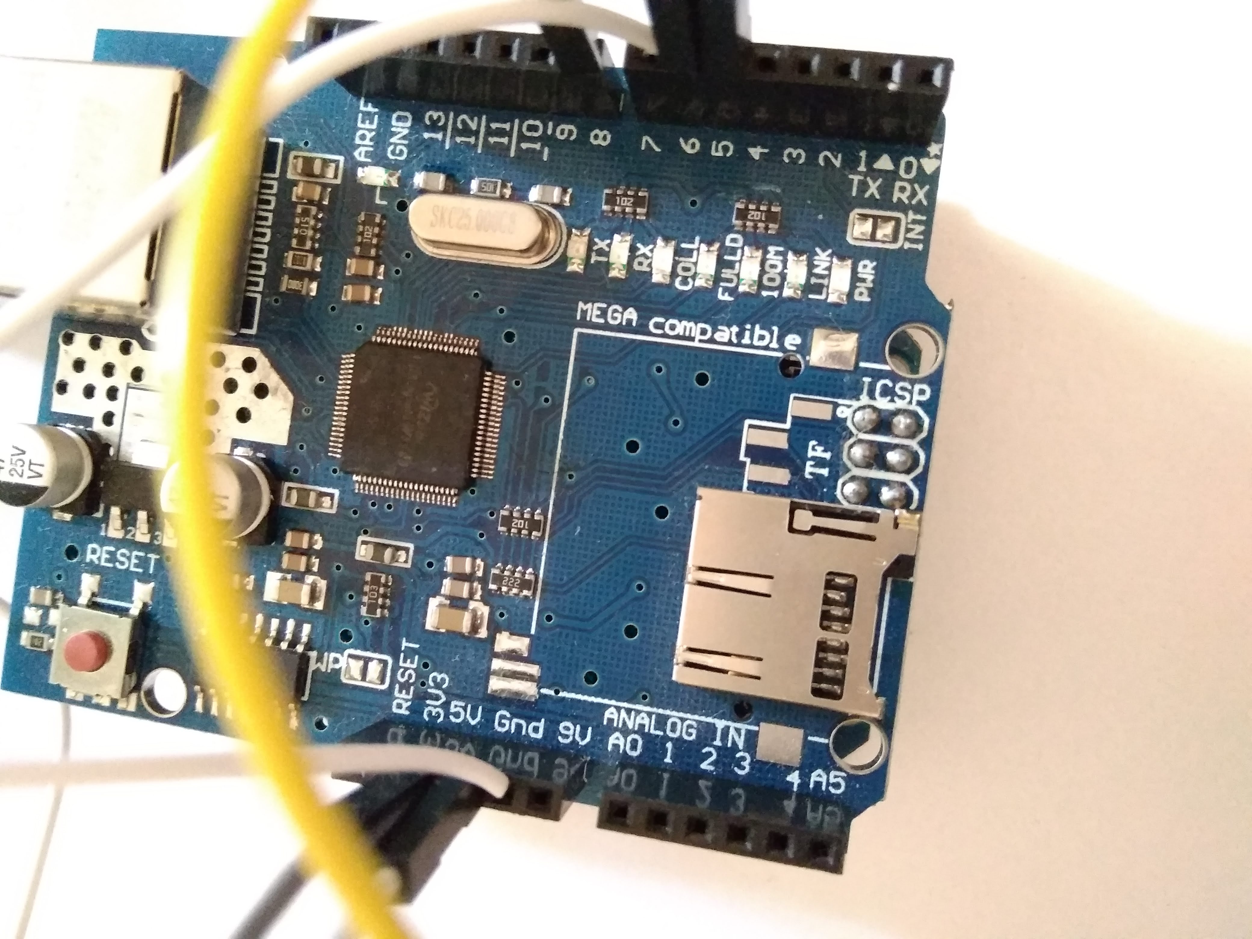
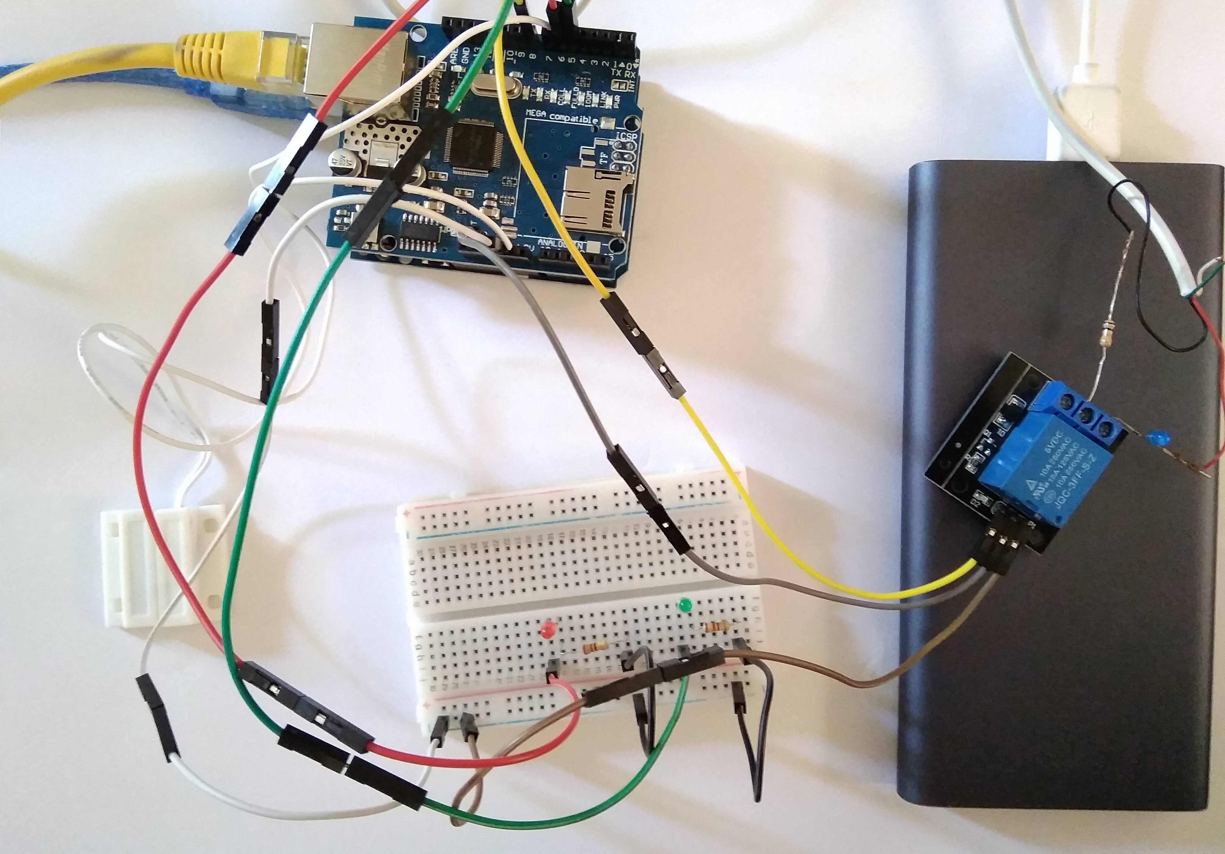
Connections
Relay Module:
To Arduino
- S ----> D8 (Digital I/O pin)
- + ----> 5V
- - ----> GND (Ground)
To LED (Prototype): This is a model to show how the connection with mains supply and bulb works.
Assumptions:
- Mains Supply - Power Bank (10000mAh)
- Bulb - LED
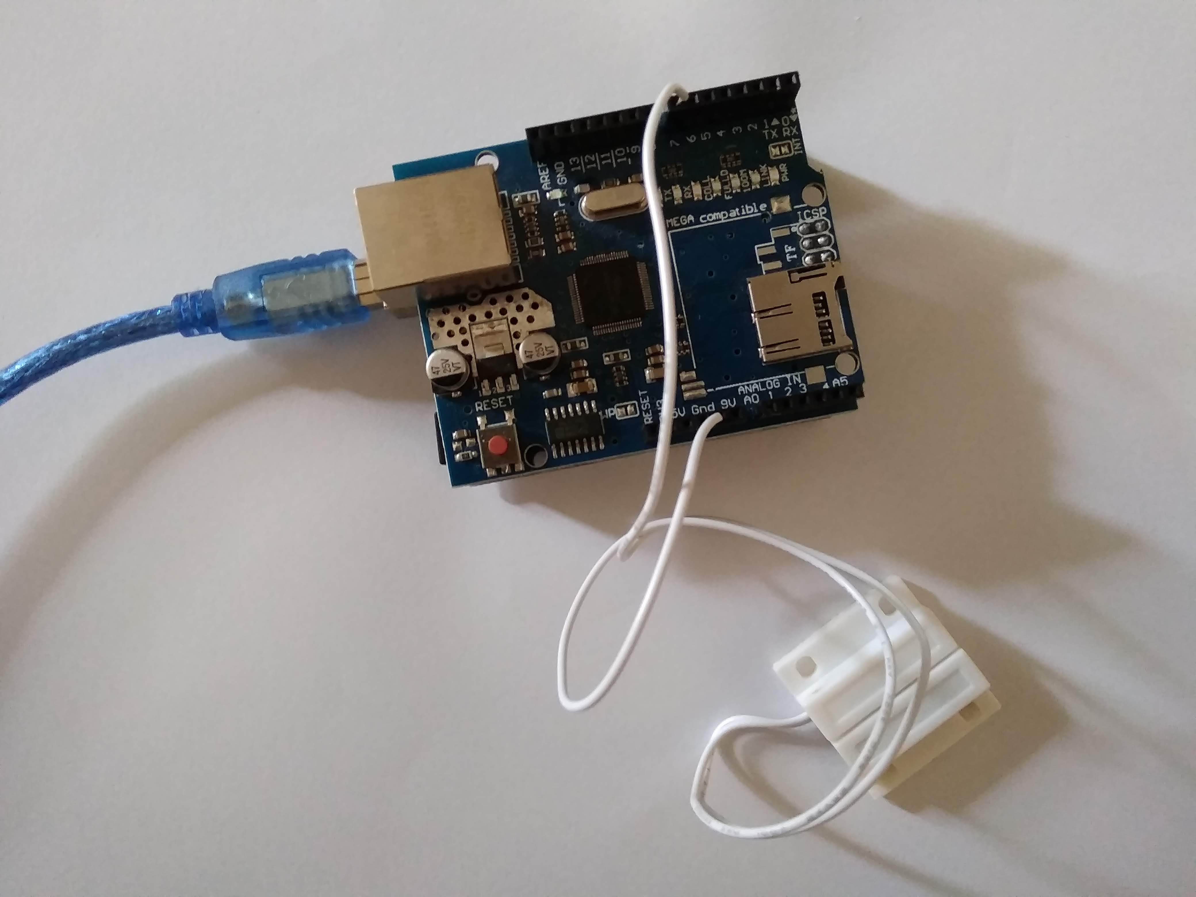
Magnetic Door Sensor:
One wire is connected to GND and the other connects to D7.
LED:
The anode (+, long leg) of the LED is connected to the digital I/O pin while the cathode (-, short leg) of the LED is connected to the Ground.
- Red - D6
- Green - D5
Setting Up Your Software
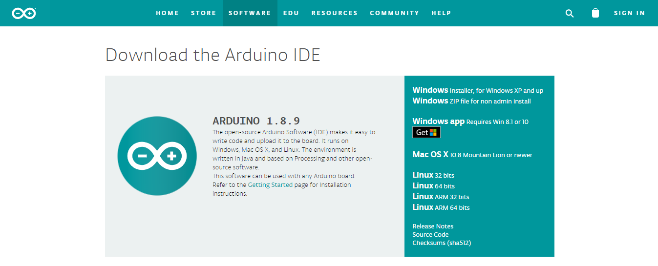
Step 01: Installing Arduino IDE
You will need Arduino IDE software to program your Arduino Uno.
Download the software by using the link below:
https://www.arduino.cc/en/main/software
Choose the compatible format to download the suitable software for your PC (or laptop).
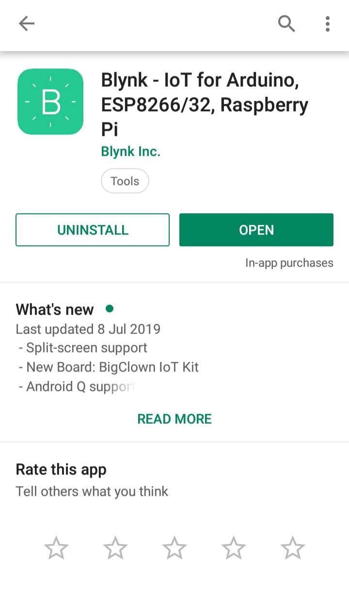
Step 02: Installing the Blynk app by Blynk Inc.
You can get the app from either Play Store or App Store ( for Apple iOS).
I have used Play Store to install this app.
In this project, I have used Blynk app to arm/disarm my magnetic door sensor.
Considering the aim of this project, you can arm the sensor when it is dark or at night and disarm when the function of the sensor is not required.
Step 03: Setting up Blynk app
- First, you will need to login using your email address or by Facebook account.
- Then you must create a new project by tapping the '+' button on the top.
- Name your project. I have named mine as 'Door Switch'.
- Choose your device. In this case you must choose Arduino UNO.
- Select your connection type. I have selected connection type as Ethernet.
- Choose the theme (optional)
- And finally, tap on 'Create Project'.
- You will receive an Auth token via email.
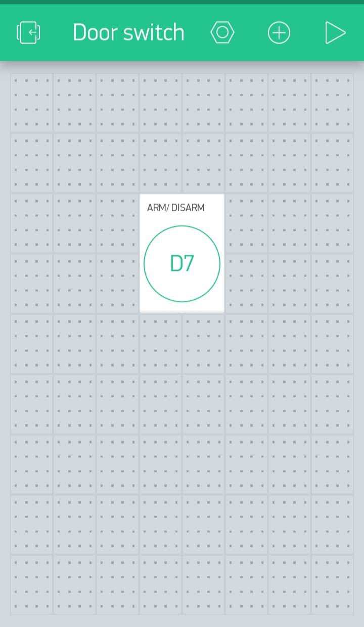
Step 04: Creating Button to Arm/Disarm magnetic door sensor
- Tap on the '+' button on the top.
- The Widget Box will appear and you will have an energy balance of 2,000.
- Tap on 'Button' option from CONTROLLERS section.
- Tap on the button created and its settings will open up.
- Change the title to 'ARM/ DISARM'.
- Select the OUTPUT pin to D7 as the magnetic door sensor is connected to that pin.
- Change the MODE from PUSH to SWITCH, by simply tapping on the black circle.
- Change the design as you desire.
The final look must be similar to that in the photo above.
Coding
Programming your Arduino Uno to perform the task and connect to the Blynk app
As you can see in the image from step 1, the circuit consists of two LEDs connect to the solderless breadboard. The Green LED indicates that the Arduino Uno R3 is connected to a power supply and that the door is closed(when the sensor is armed). The Red LED indicates that the door is opened (when the sensor is armed).
You will need to install Blynk library in your Arduino IDE software. You can do this by:
- Going to Tools and select 'Manage Libraries...' option.
- The Library Manager opens up and type 'Blynk' in the search bar.
- You can see the first option: 'Blynk by Volodymyr Shymanskyy'.
- Click on that option, select the latest version and install the library.
https://blynk.io/en/getting-started
The codes used for connecting the Arduino Uno R3 to Blynk app was taken from the Blynk Example Browser. I modified the codes to make it compatible with my model and added some codes to make my Arduino Uno R3 perform the task. For the '#include' functions, you must go to 'Sketch' and include the suitable library.
// Project by Rucksikaa_R
// For Instructable Sensor Contest
#define BLYNK_PRINT Serial
#include <SPI.h>
#include <Ethernet.h>
#include
char auth[ ] = " "; // You must include the Auth token(sent by Blynk) with the quotes.
// You should get Auth Token in the Blynk App.
// Go to the Project Settings (nut icon).
#define W5100_CS 10
#define SDCARD_CS 4
int prevState = -1;
int currState = -1;
long lastChangeTime = 0;
const int RELAY = 8;
const int GREEN = 5;
const int RED = 6;
int val=0;
void checkPin() {
// Invert state, since button is "Active LOW"
int state = !digitalRead(7);
// Debounce mechanism
long t = millis();
if (state != prevState) {
lastChangeTime = t;
}
if (t - lastChangeTime > 50) {
if (state != currState) {
currState = state;
Blynk.virtualWrite(V1, state);
}
}
prevState = state;
}
void setup() {
// Debug console
Serial.begin(9600);
pinMode(SDCARD_CS, OUTPUT);
digitalWrite(SDCARD_CS, HIGH); // Deselect the SD card
Blynk.begin(auth);
pinMode(7, INPUT_PULLUP); //Door Sensor is connected to D7
pinMode(RELAY,OUTPUT);
pinMode(GREEN,OUTPUT);
pinMode(RED,OUTPUT);
}
void loop() {
Blynk.run();
checkPin();
val = digitalRead(7);
if (val==HIGH){
digitalWrite(RELAY,HIGH);
digitalWrite(RED,HIGH);
digitalWrite(GREEN,LOW);
}else{
digitalWrite(RELAY,LOW);
digitalWrite(RED,LOW);
digitalWrite(GREEN,HIGH);
}
}
Testing Your Model
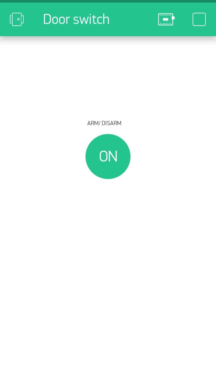
Everything is complete now. All you have to do is test your model.
To connect your Arduino UNo to Blynk application, tap on the play button and shortly afterwards you will see the message, 'Device is connected'.
How my model works:
- The Green LED will be lit up as long as the Arduino Uno R3 is connected to a power supply even when the magnetic door sensor is disarmed.
- When the magnetic door sensor is armed, and the door is opened, the Red LED lights up and the relay module is switched on.
- When the magnetic door sensor is disarmed while the door is opened, both the Red LED and Relay module are switched off, and the Green LED lights up.
I hope you enjoyed this project!