Controlling High Voltage Devices With LinkIt One
by LightBug in Circuits > Microcontrollers
1889 Views, 22 Favorites, 0 Comments
Controlling High Voltage Devices With LinkIt One
In the past few projects I have been using the LinkIt One board and the LinkIt One board is great for IoT applications. But the LinkIt One is not capable of handling high voltage and current devices, like for example your home lighting system or any other higher voltage devices. For this we may need a MOSFET, a MOSFET or metal–oxide–semiconductor is a type of transistor used to amplify controlling signals like 5V from the LinkIt One to say 12V.
Why cant I use a relay?
A relay is also a good device, but has certain limitations like slower switching rate, with a realy we may reach around a few hundred hertz of frequency, but a MOSFET is capable of handling frequencies upto 5MHz which is much much faster than a mechanical relay. Relays also make a lot of noise while it switches which is eliminated while using a MOSFET.
So in this instructable I'm going to show you how to control lights and motors using MOSFET.
So lets get started....
Tools and Components
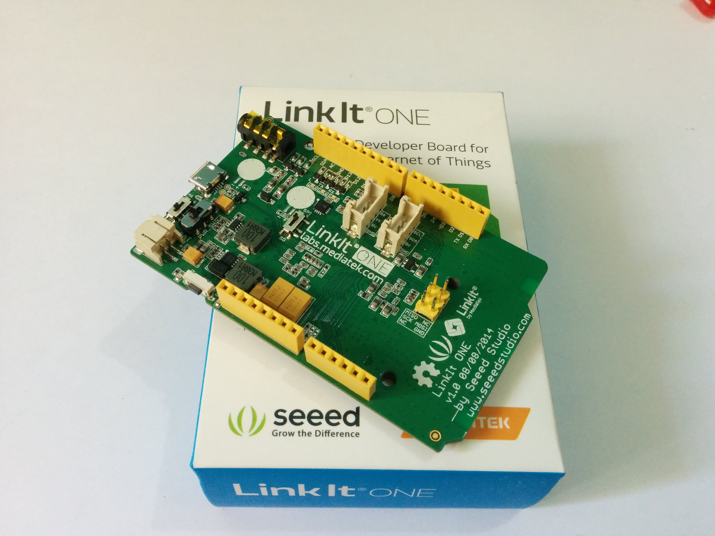
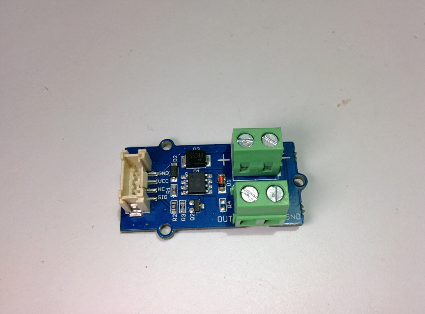
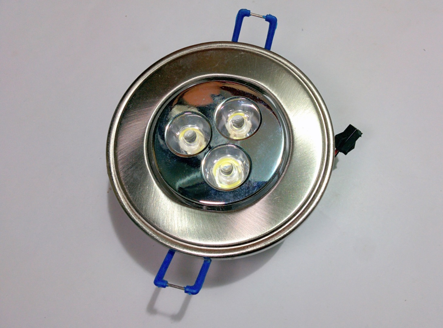
All that you need for this instructable is -
- LinkIt One Board
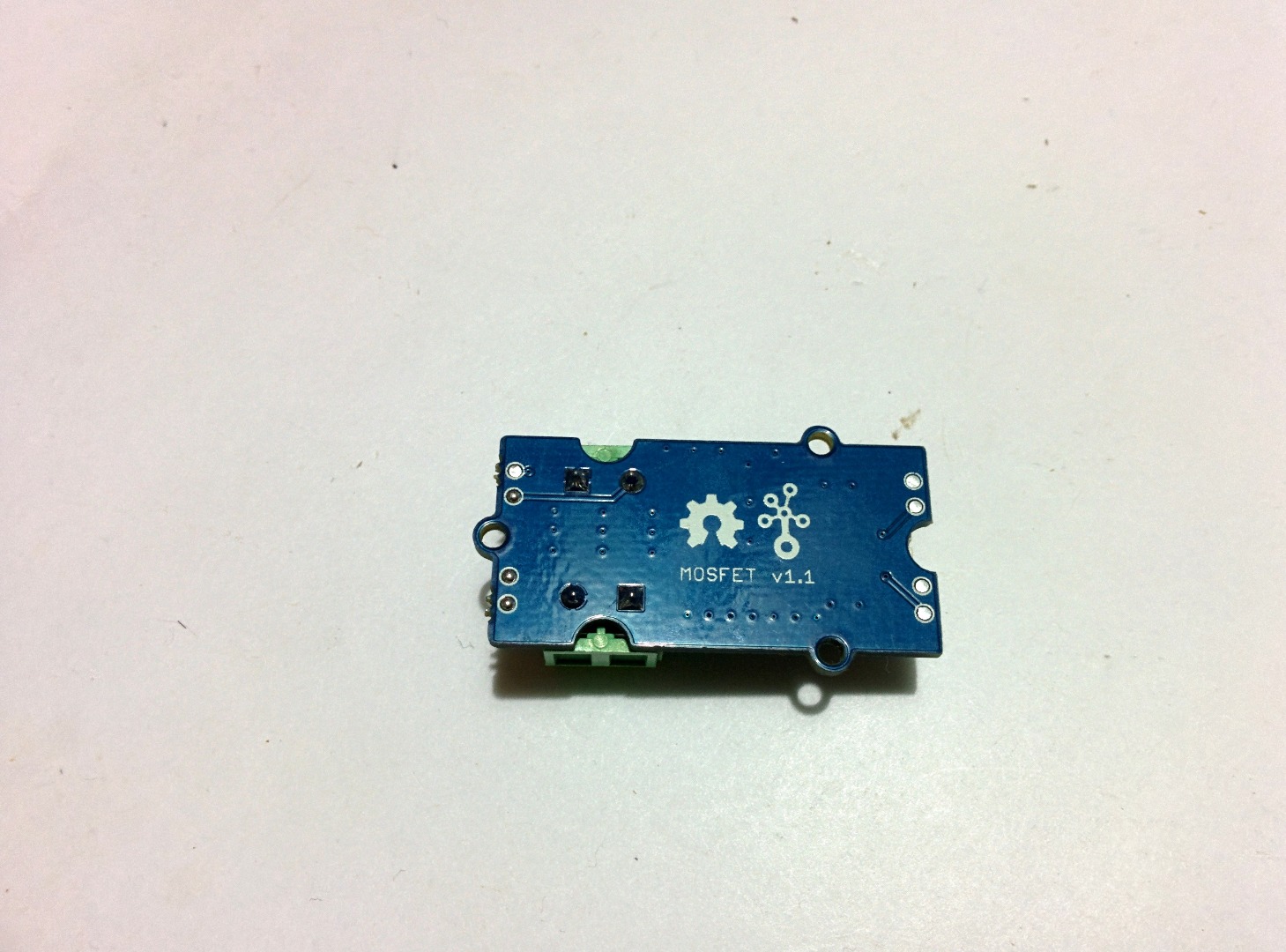
- Grove MOSFET
- 12V LED lights
- 12v DC Motor
- 12 DC Voltage source
- Breadboard
- Jumper wires
Circuit
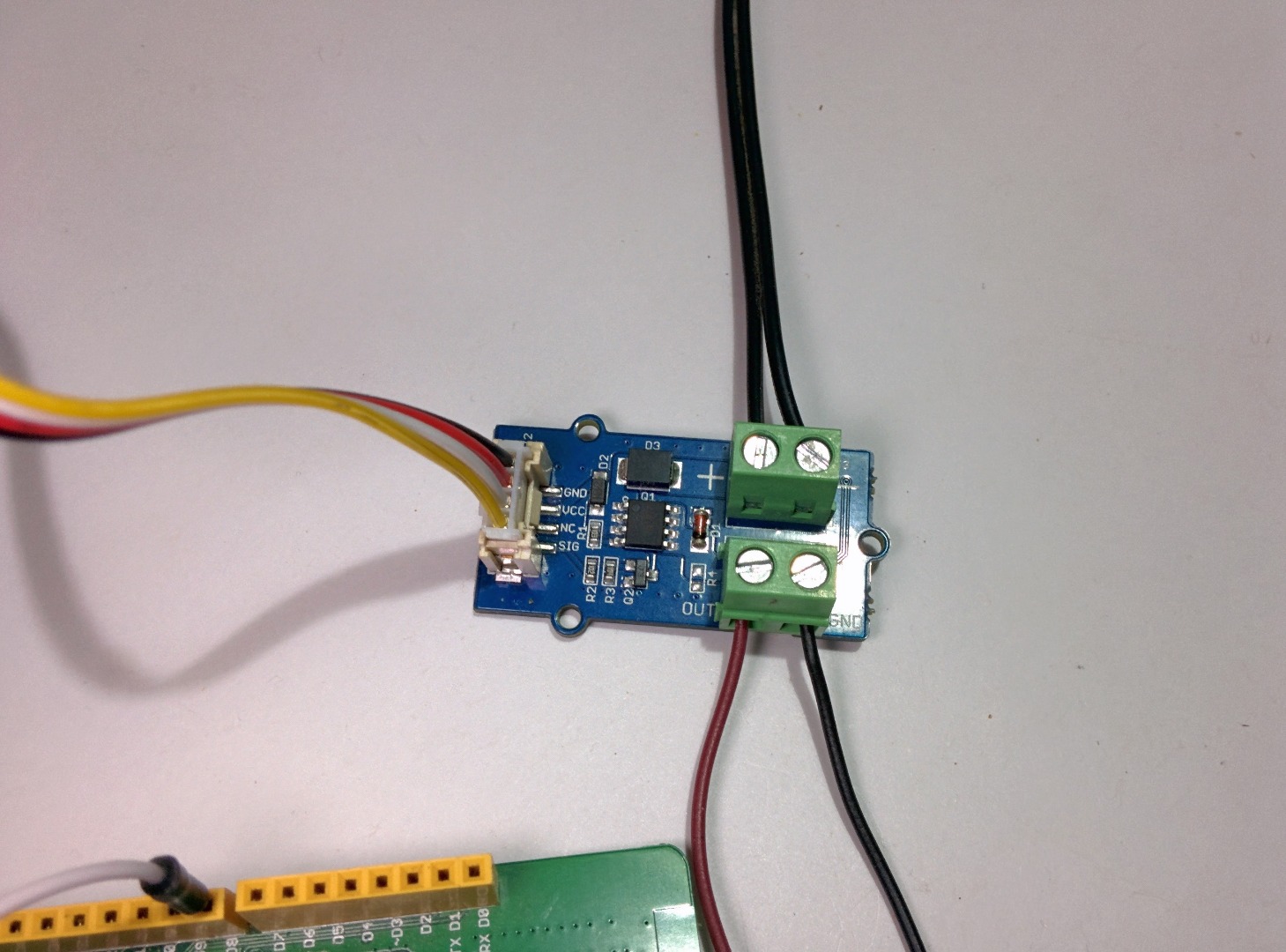
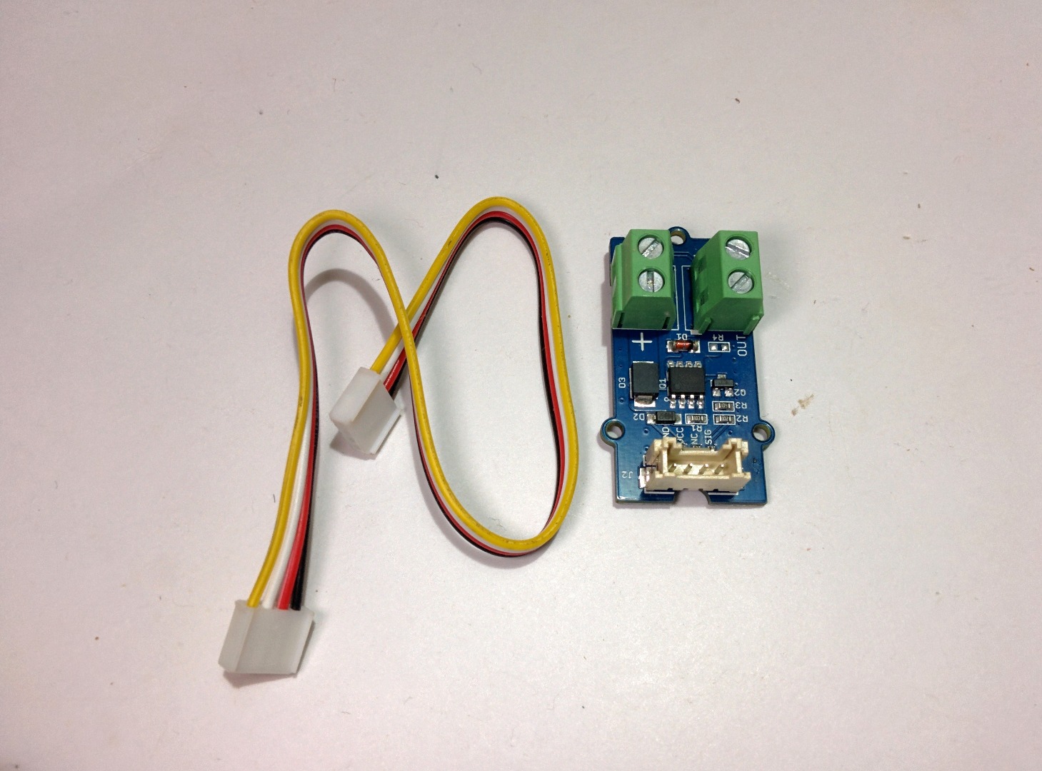
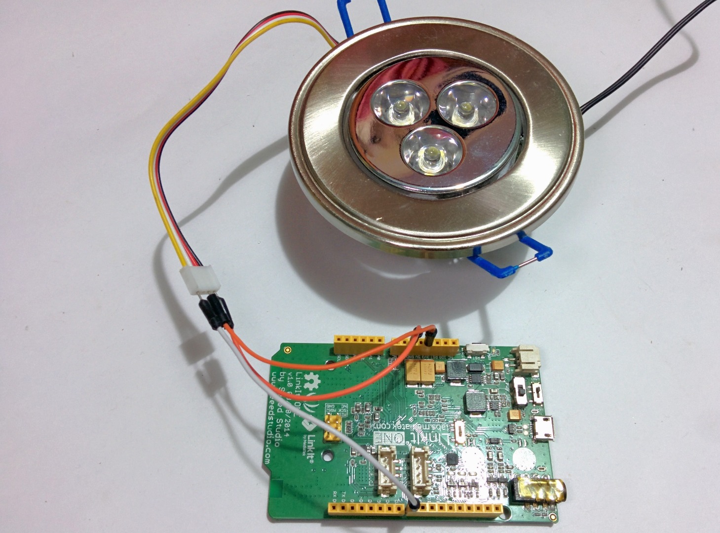
For the first part of the project I will show you how to control home lights using a LinkIt one and grove MOSFET. For the lights I used a 12 LED lamp, so we would be controlling 12V using a 5V signal from the LinkIt One. The positive wire from the lamp goes to the screw terminal where it says Out and the Gnd terminal goes to Gnd.
The DC power source connects to the board where there is a negative and a positive sign. With the help of the ribbon cable which came along with the board connect the MOSFET to the LinkIt One board and the connections goes as follows -
- Grove MOSFET VCC TO LinkIt One +5v
- Grove MOSFET GND TO LinkIt One Gnd
- Grove MOSFET Sig TO LinkIt One Digital pin 8
Code
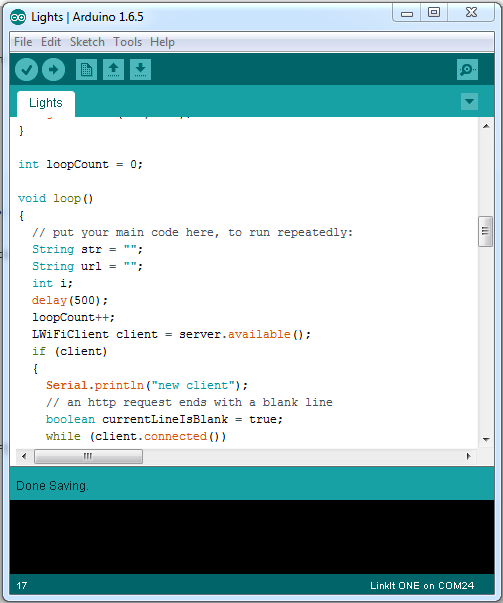
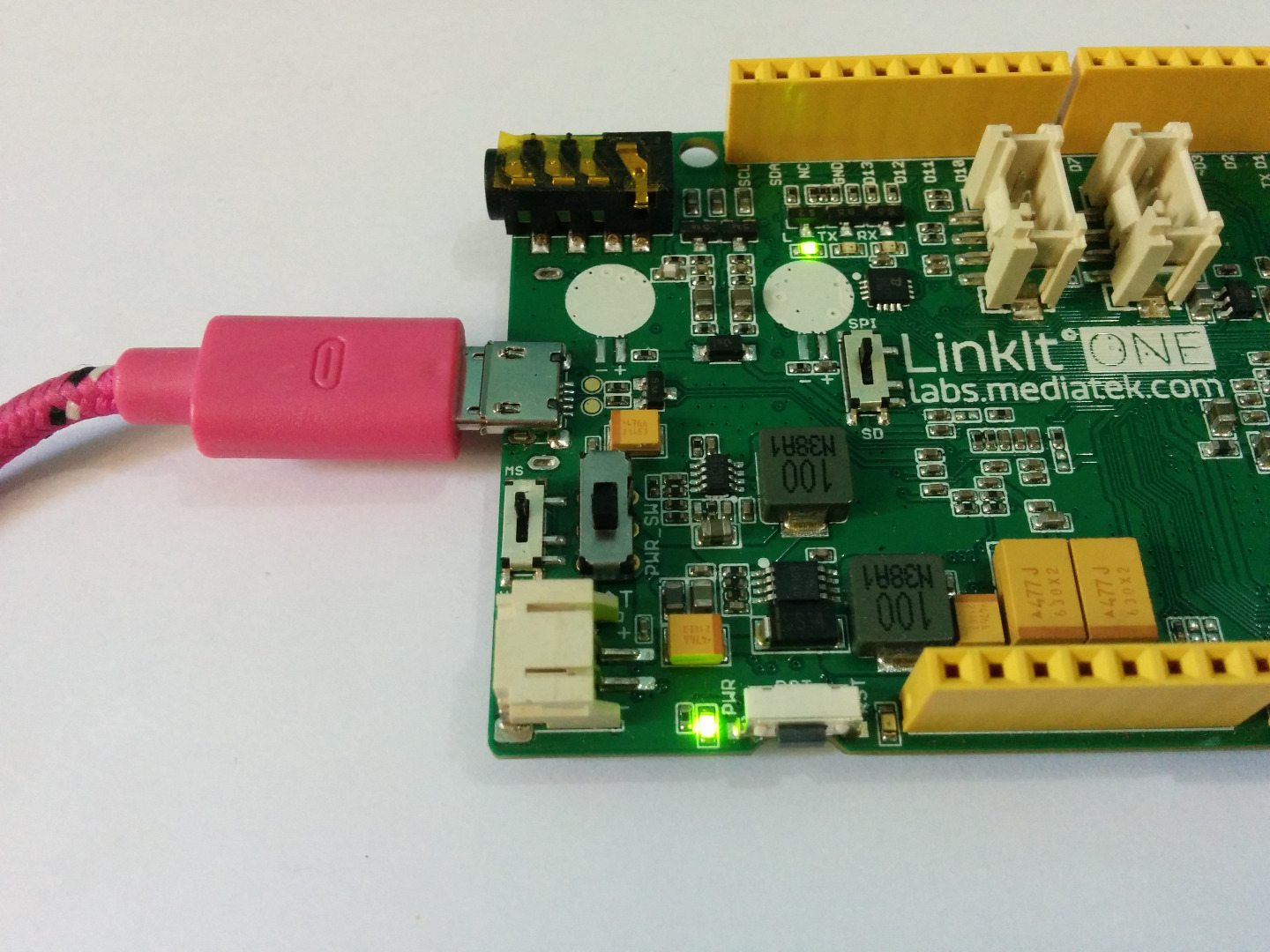
The code can be found below, make sure you edit the fields where it says network SSID and network password with your WiFi name and password. Upload the code using an the Arduino IDE with the link it one plugin. Instructions on how to install the plugin can be found in the first instructable of this series.
Downloads
Testing

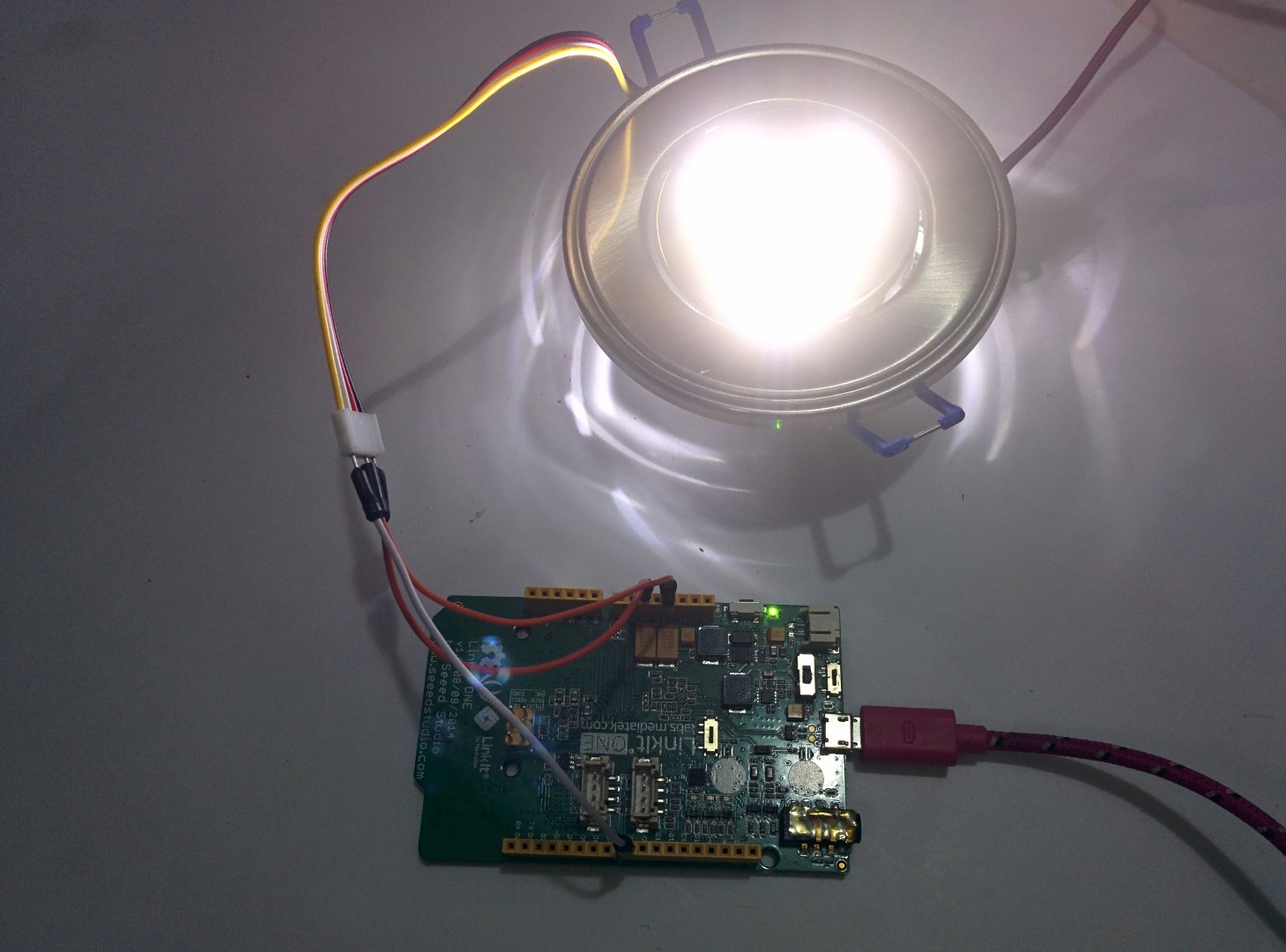
You can control the Lights from a web browser by entering the LinkIt One's IP address on a web browser. If everything went fine you should see the lights tun on when you click on the ON input button on the web page. You could also check the frequency of the MOSFET if you are using an LED lamp like I am doing. You can upload the code below. The code makes the lamp blink at a frequency you set.
You can change the frequency by editing the value of delay() in the code by default it is set to 1Hz.
Controlling Motors
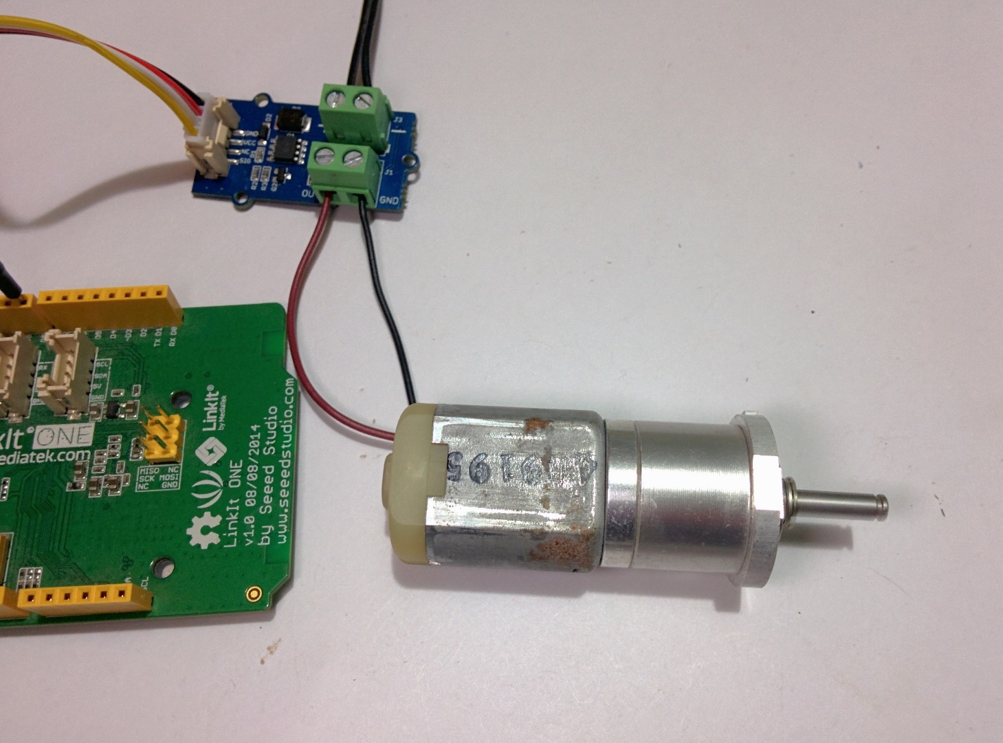
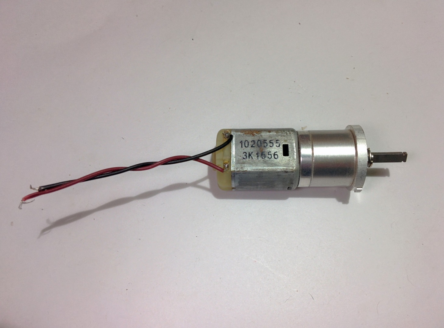
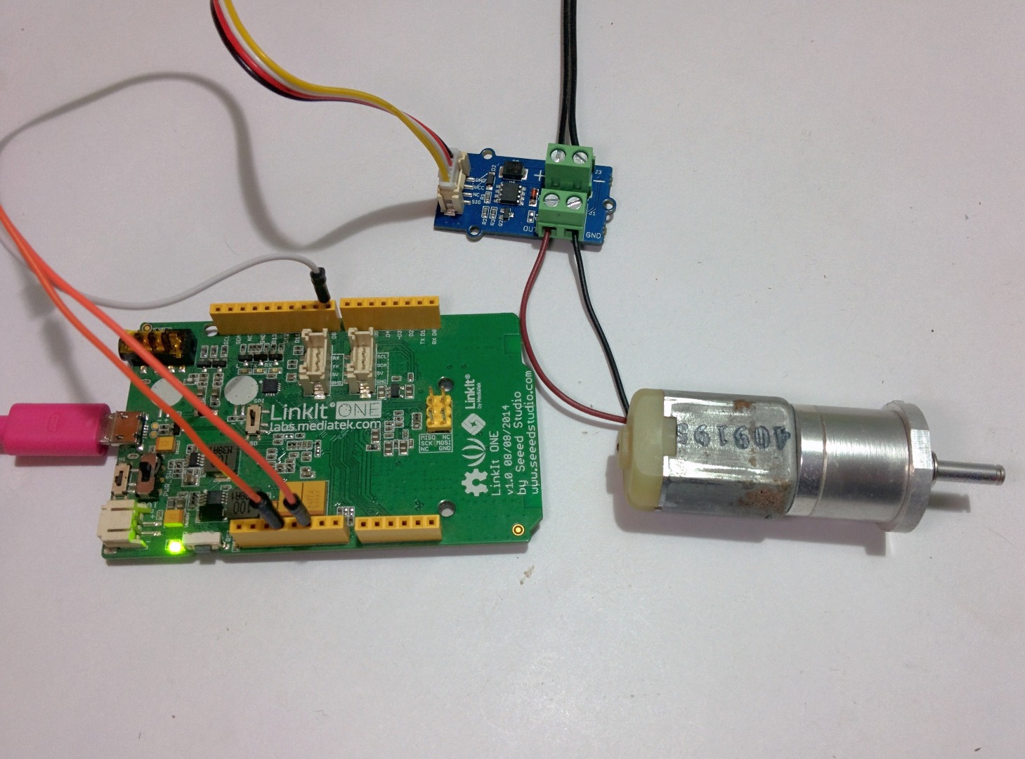
For the second part of the project I will show you how to control motors using a MOSFET, for this I'm using a 12V DC motor and I will be powering it with the same 12V DC Voltage source as before The connections are almost the same as before and Here is how it was -
- Grove MOSFET VCC TO LinkIt One +5v
- Grove MOSFET GND TO LinkIt One Gnd
- Grove MOSFET Sig TO LinkIt One Digital pin 8
Code - Motors
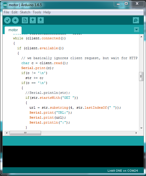
The code for controlling the motors is almost the same as that of the light controlling.
The code can be found below, make sure you edit the fields where it says network SSID and network password with your WiFi name and password. Upload the code using an the Arduino IDE with the link it one plugin. Instructions on how to install the plugin can be found in the first instructable of this series.