ControllerMan S6 - Arduino Midi Programmable Stomp
by mrandisi in Circuits > Arduino
6762 Views, 25 Favorites, 0 Comments
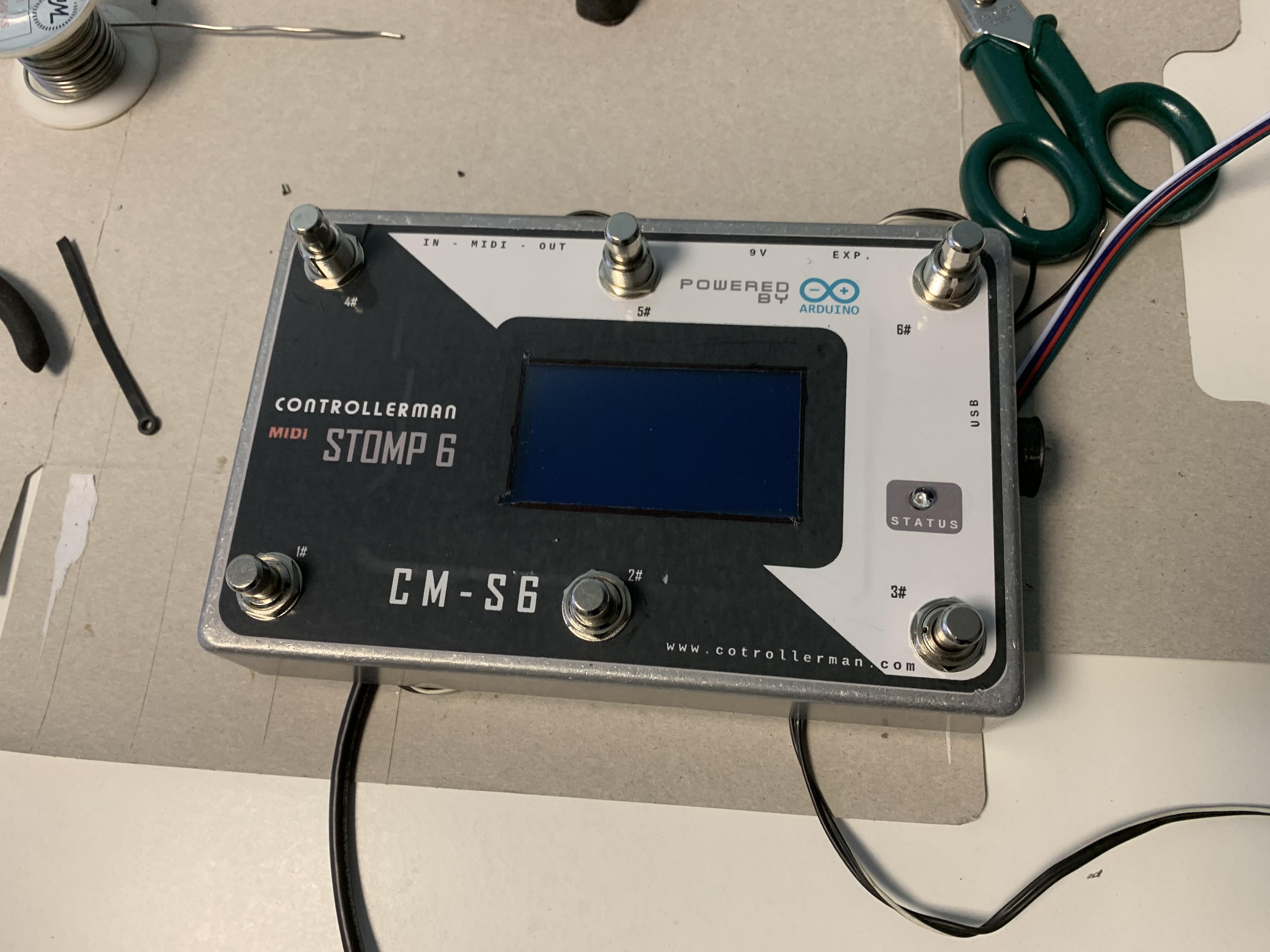
ControllerMan S6 - Arduino Midi Programmable Stomp
The moment you start looking for a midi controller is the same as you start having to study how the midi protocol works. Normal people would look for the midi controller that suits them but the Maker is not satisfied and wants to do more: this is why we are here. Arduino is a great platform to control the midi protocol and you just need few more components to make it working. Then, you have to choose what to do to get the best.
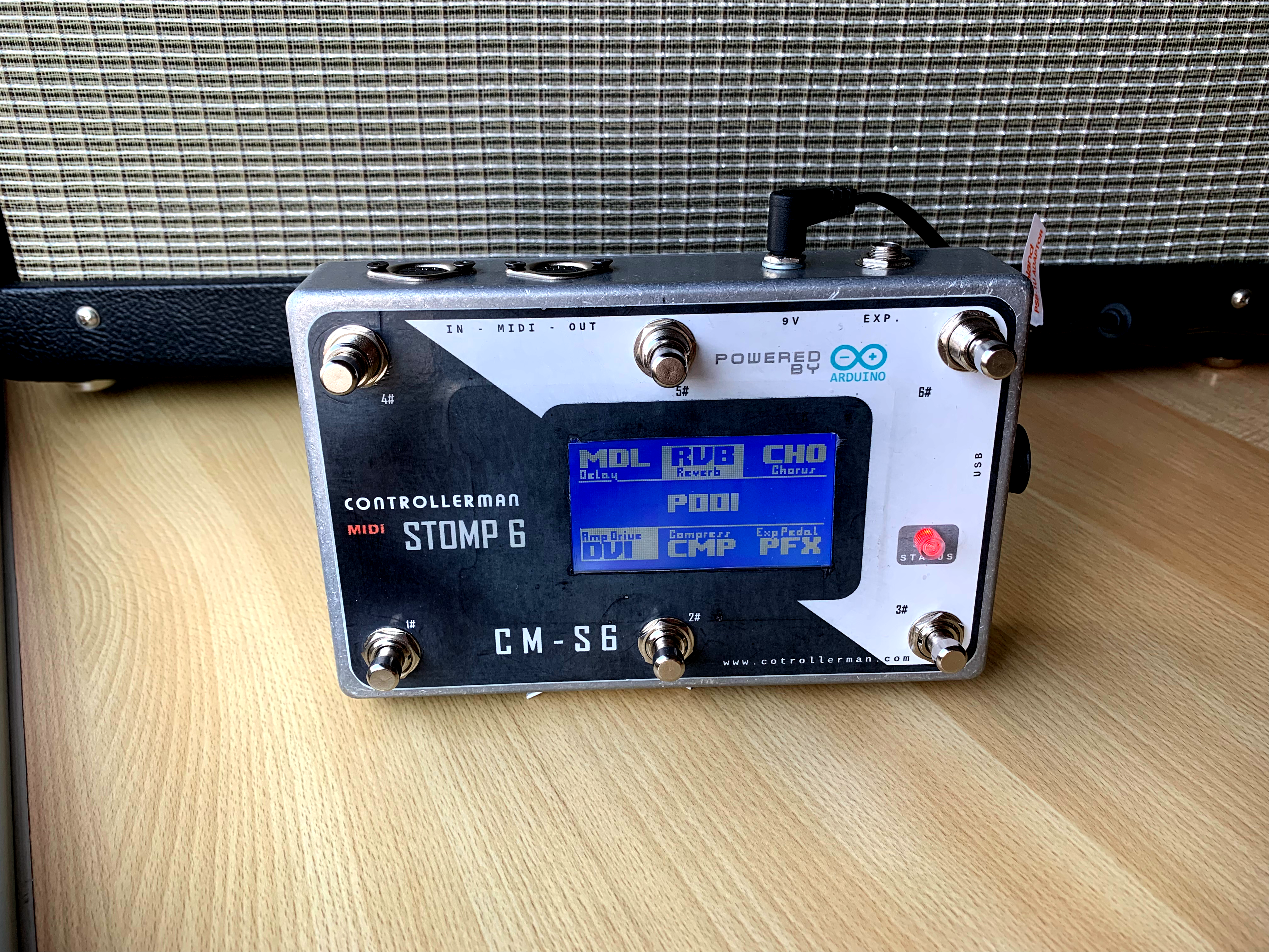
You need to choose the right size to get the best compromise between space and functionality. I can say that more is better but not everything is necessary at the same time so I decided to create the Layouts. In this project you have six buttons but switching trough four layouts you can have 24 virtual buttons! Every layout is identified by a color (red, green, cyan and purple) and the RGB led lets you know anytime where do you are. And this is just the begin because every button can be configured to support Double-tap and Long-tap functions so, in a single layout you can access up to 18 functions as well.
You also need to know what a button does and this is the begin of the problems so becomes necessary to use a display. A large display lets you read everithing when you are standing.
Every component has been purposely choosen to be easily available on the web.
Supplies
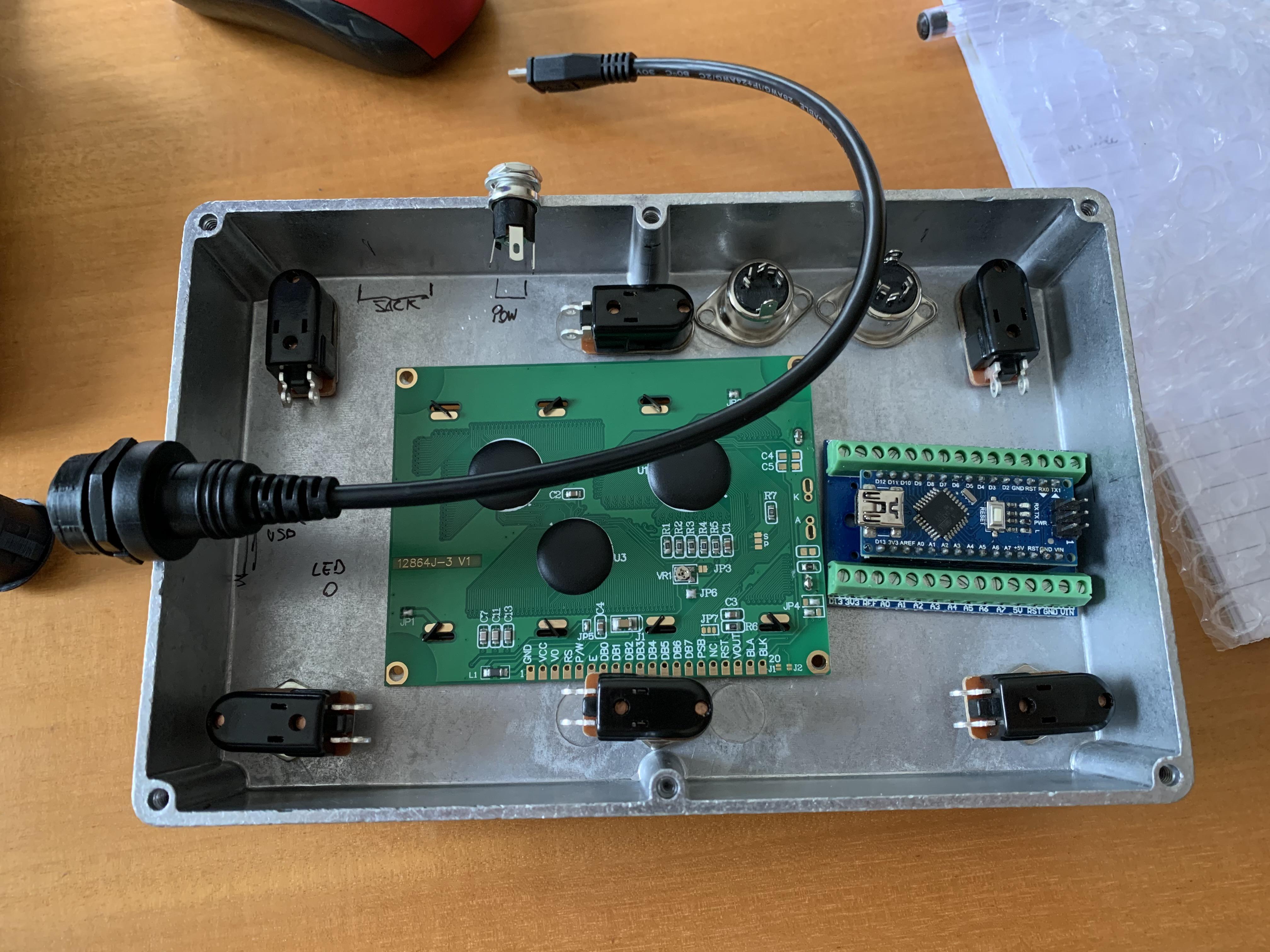
- Arduino nano with terminal adapter;
-
1590DD alluminum chassis (187x119x33);
-
LCD Display 128x64 ST7920 5v;
-
6 momentary stomp box buttons;
-
1 RGB led common cathode;
-
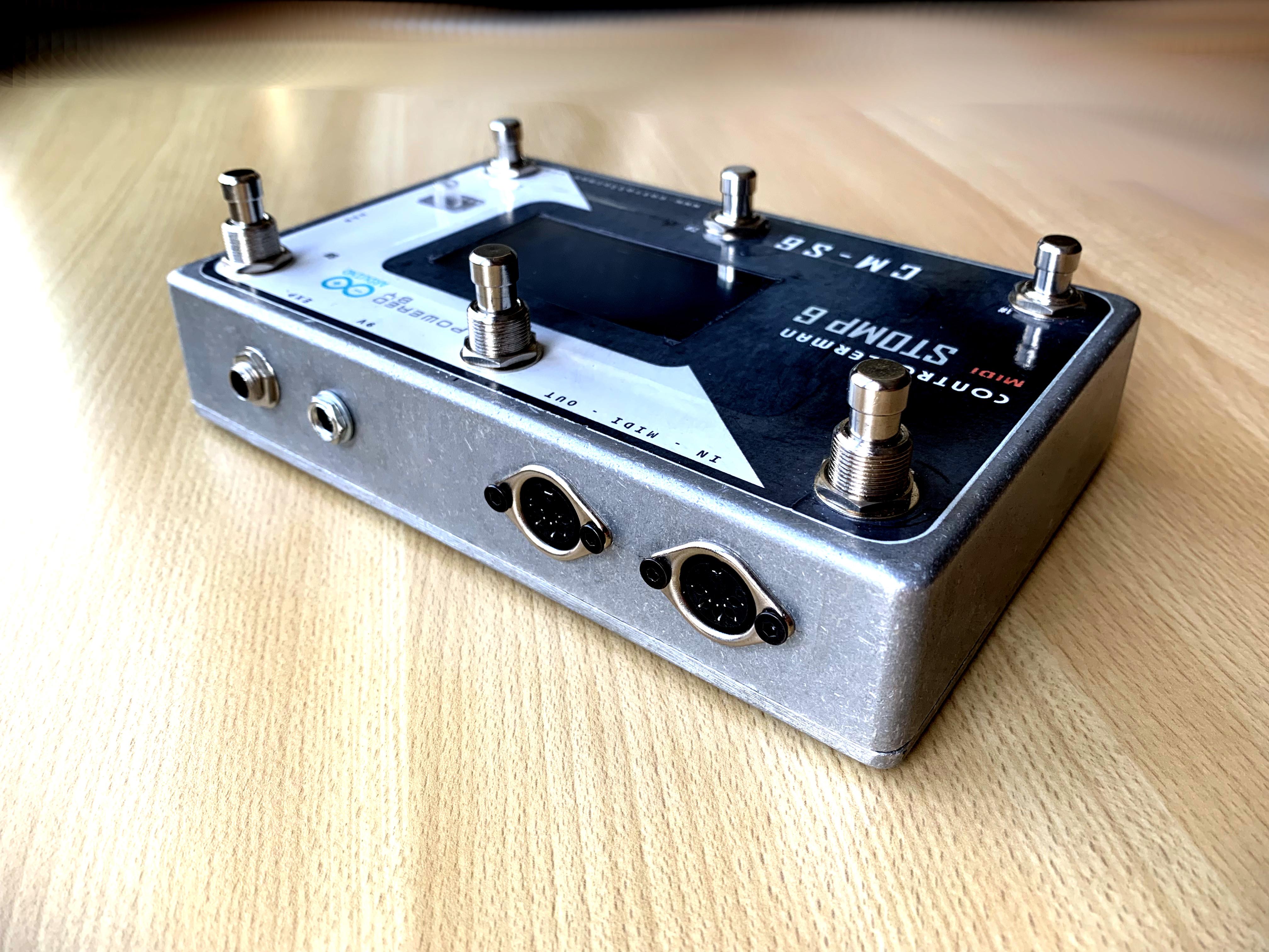
sockets for Midi and power;
- socket for 9v power and a 1N4001 diode for for reverse power protection (any 1n400x series will be fine);
-
screws and PCB spacers;
-
drill and fretsaw
- The source program: https://github.com/mrandisi/controllerman
Let's Get It Started!
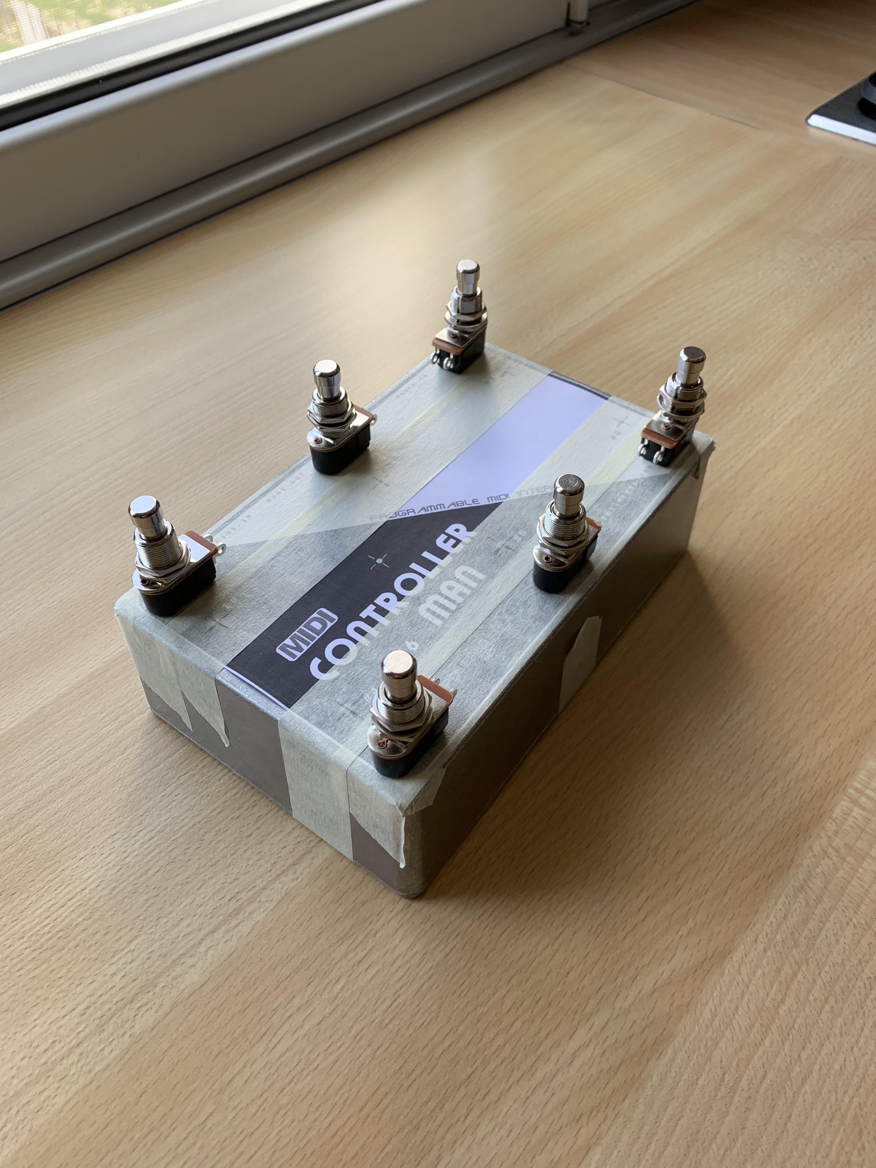
Once you've got the components, you need to do a great job to drill the aluminum box. It needs a lot of manuality to do it so I decided to give only the major guidelines.
To begin, sign with a pencil the button positions to make the hole. Make sure that internally you have space for the bolts: the box has the beams for his screws! Afterwards you can choose the right position for the display keeping in mind to left space for the Arduino socket on one side and the RGB led on the other. Make the same for the sockets on the back panel. A new set of drill bits for metals will be you best friend to cross the aluminum without effort.
Drilling the Box
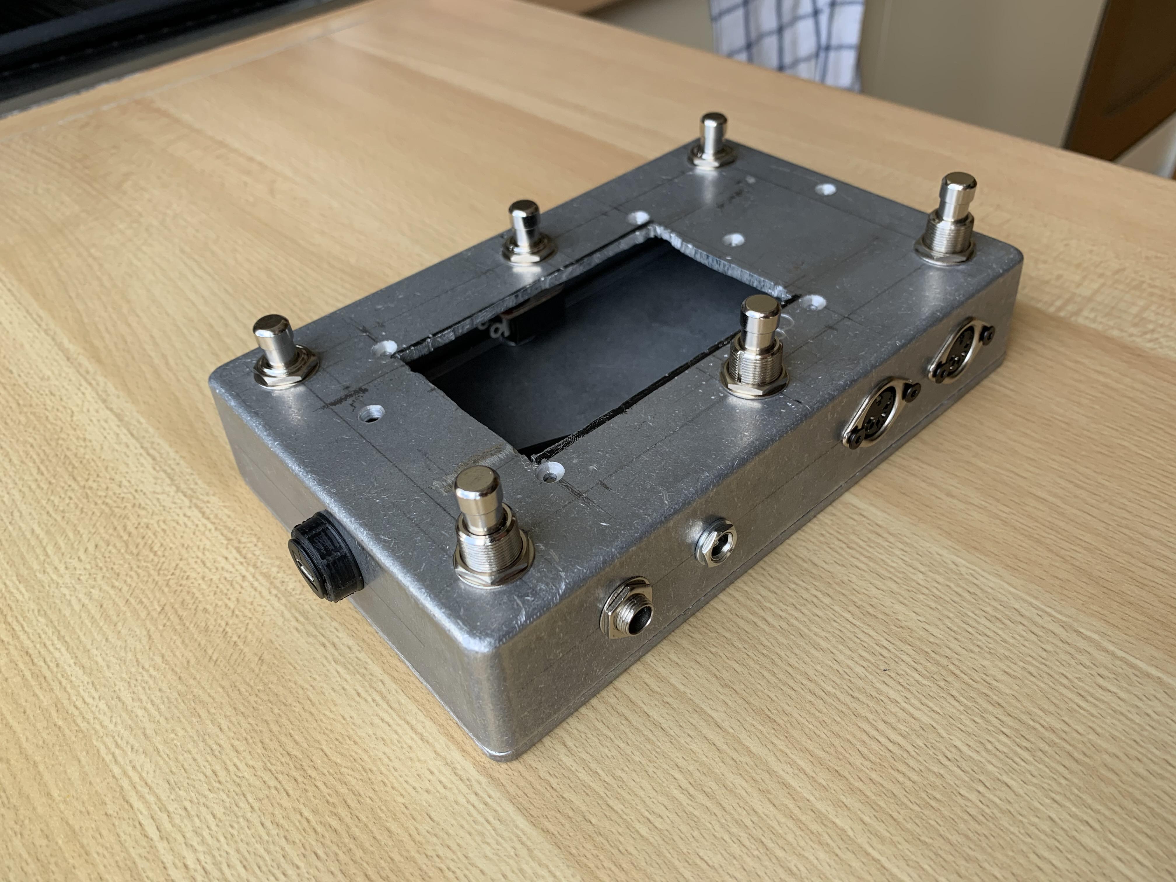
To make the holes begin from a small one. Enlarging it will let you keep the center with more precision.
The worst comes with the display's hole. You need a fretsaw and a lot of patience. I suggest to divide the work in two or three days. Make sure to design well the footprint, you will not have a second chance! To begin you must first make a hole with the drill. Then remove the blade from the hacksaw and reassemble it by passing it through the hole.
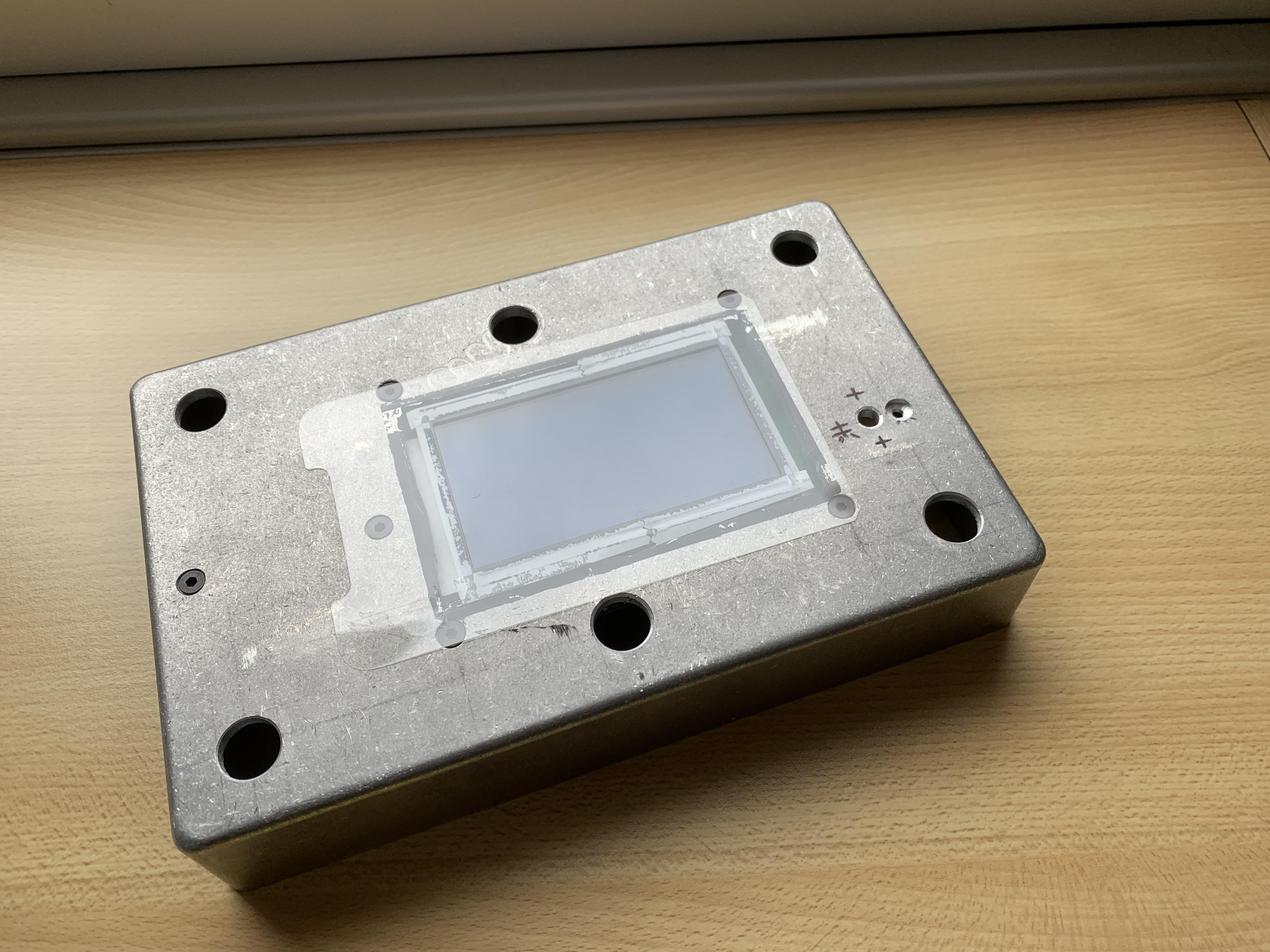
Installing the display, make sure that is in line with the surface of the box. To protect the display, cut out a phone film large enough to cover the entire hole. Apply some strips of double-sided tape around the display frame, then attach the film - dust will no longer be a problem.
You can download here the graphics: https://bit.ly/CMS6Graph
Print a low quality preview before the final sticker, to make sure it fits well. You can edit it with Gimp to let your printer realize the perfect size. Take the cutter and make a hole for the display. Don't be in a hurry to attach it - make sure all the front screws have been mounted.
Install the Source Program on Arduino
To proceed you need the Arduino IDE: go to https://www.arduino.cc/en/software and get the right one for your platform if you haven't done so yet.
You also need the controllerman program. Get it on https://github.com/mrandisi/controllerman . It contains the main program controllerman.ino and two library headers with the implementation inside: DeviceSettings.h and Display.h .
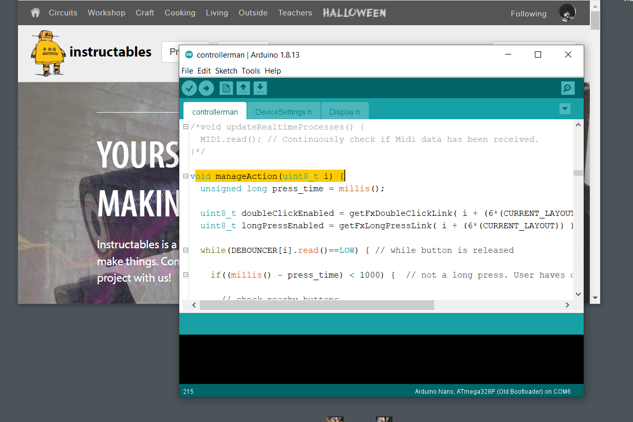
Copy the controllerman folder to your arduino projects folder and open it into the IDE. Some libraries are missing, install them clicking the top menu Tools > Manage Libraries. If no error occurs you will be able to upload the sketch using the top-left arrow. If upload fails instead check that the right board is selected on both Tools>Board and Tools>Processor
The program is completely ready to run but if you need to understand the logic, begin with the manageAction() function, which checks the buttons and calls the following:
- singlePress() - the simplest click;
- singlePress_hold() - the long press;
- doublePress() - simple click on two buttons simultaneously;
- doublePress_hold() - long press on two buttons;
- doubleClick() - two subsequent clicks.
Assemble the Wires

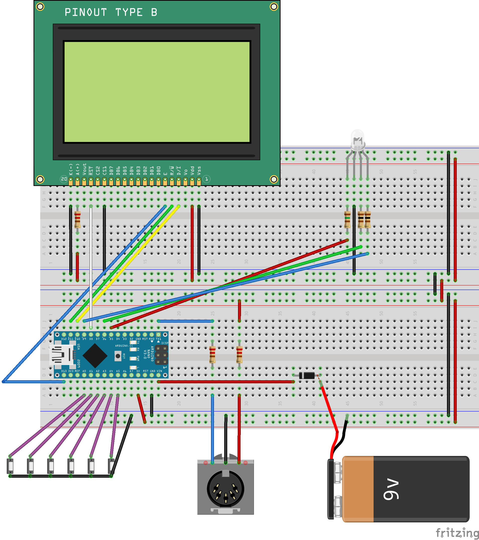
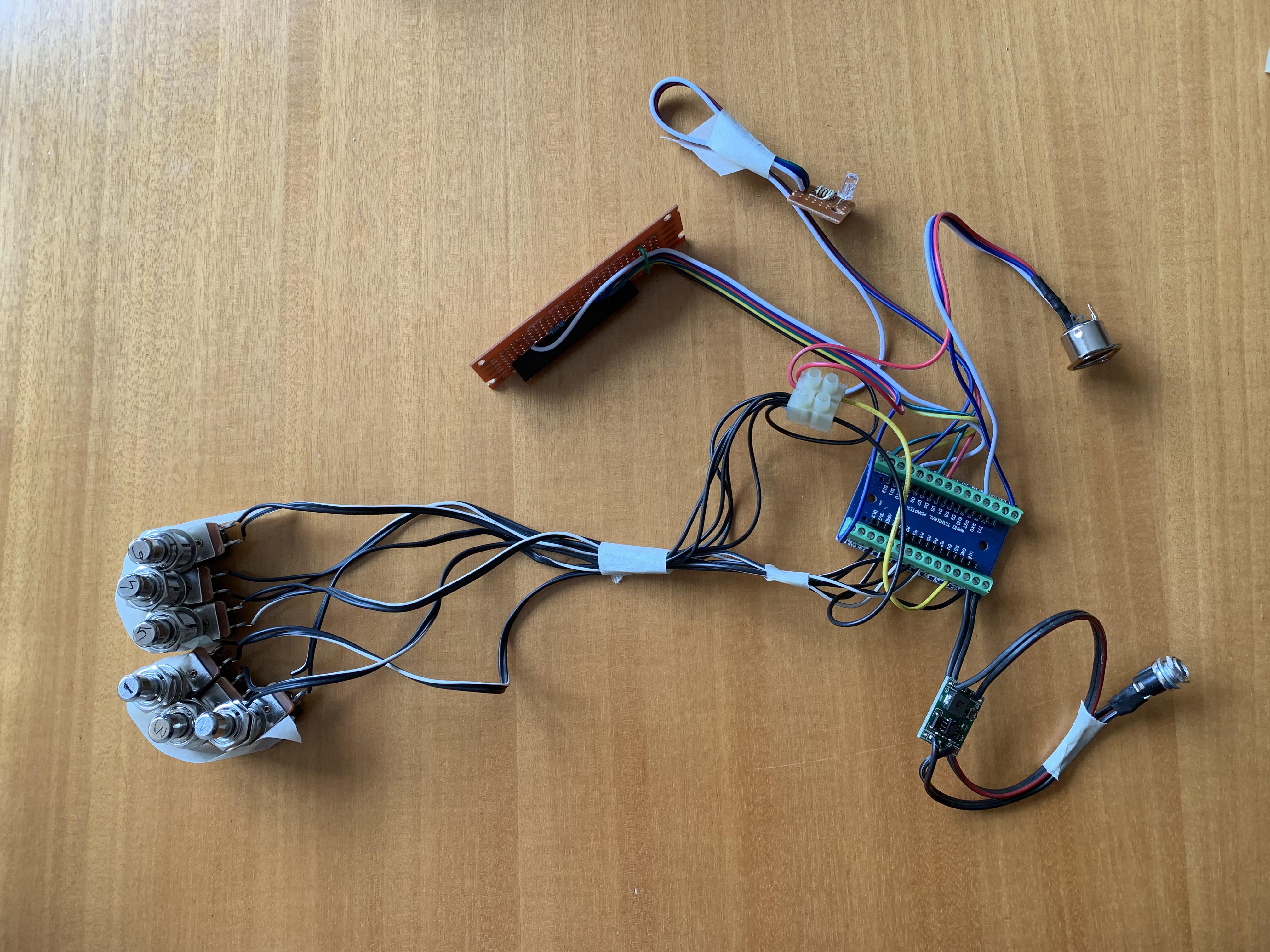
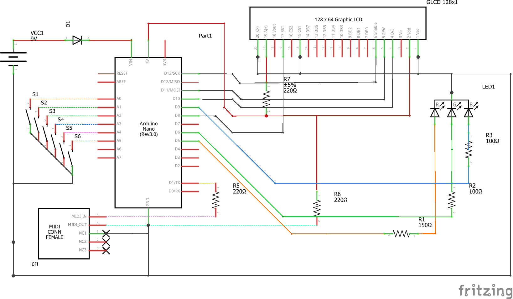
Below you can find the Fritzing .fzz document with the wirings.
You may connect the display wires directly to the Arduino's socket but you would get a clew. You need a matrix board to connect the pins, then just the necessary wires will reach the microcontroller.
All the other wirings are set at the top of the arduino schetch as follows:
- buttons: one pin on the ground, the other: 14, 15, 16, 17, 18, 19 from 1st to 6th button.
- RGB Led: 5, 8, 9. and the ground. Sold the resistors on each anode, 150ohm for red and 100ohm for green and blue.
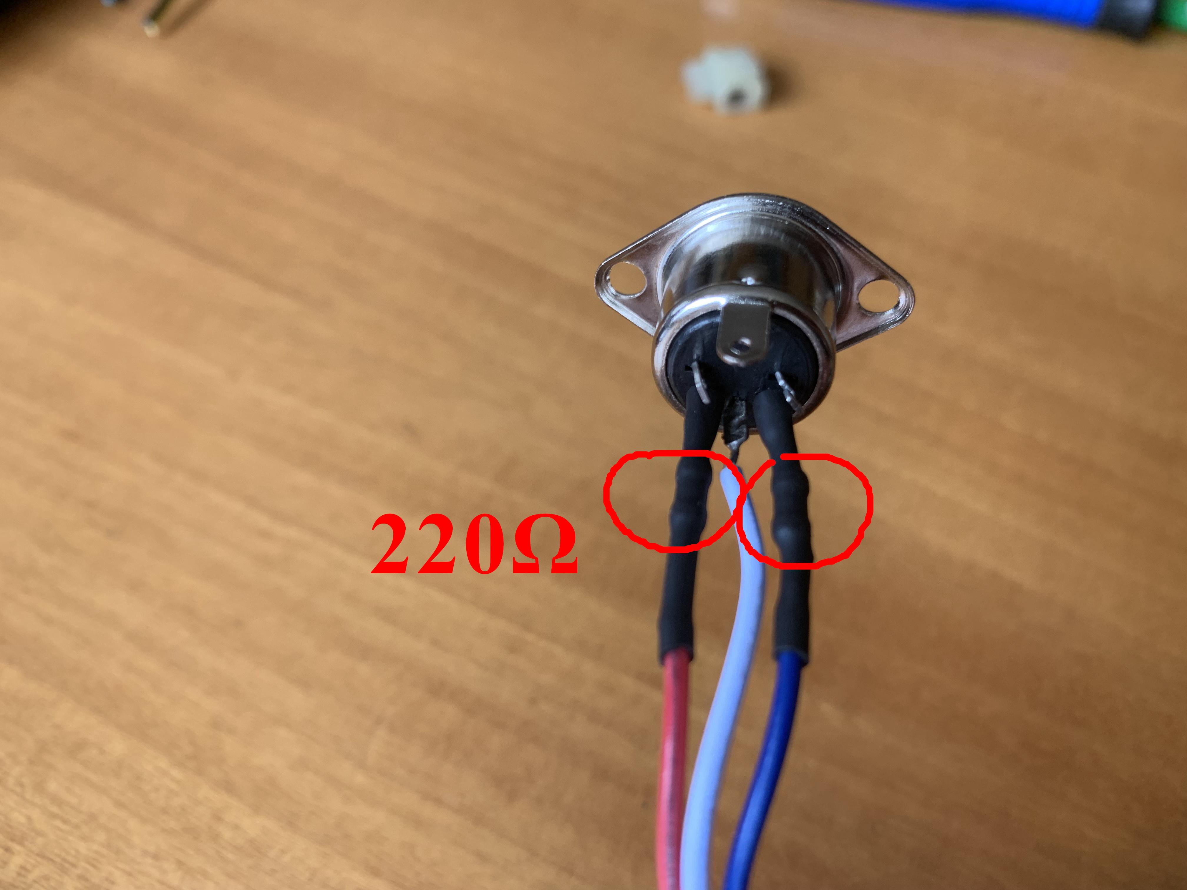
The midi out at the TX serial pin. Sold two resistors near the midi socket before connect: https://bit.ly/NotePlay
The Vin pin on arduino will let you power the controller directly with a daisy chain cable, as a 9v common effect pedal, according to the documentation it accepts from 7 to 12 volts. The diode 1n400x in series will protect in case of wrong reverse powering.
Downloads
Configure the GT1000 and Set the Controller.
The controllerman stores the effect state (on/off) for the first 125 patches. Every patch change loads all the states to the device. Make sure to use the button combination 2+3 and 5+6 to move up and down between the patches.
Using the combination 1+4 and 3+6 you can move between the layouts (red > cyan > green > purple > red) as shown in the third video. The central buttons combination 2+5 resets the layout to red wherever you are. Keep this buttons pressed for at least two seconds to enter the menu.
The combination 1+2 and 4+5 is reserved to control an analog parameter on the CC 95. Starts from 80% and increase/decrease with a step of 10%.
In the next video you can se how to configure the GT1000 to read the messages. Going to menu > control assign > assign settings you can choose a slot, select your preferred target and assign a Control Change Number. Make sure that the mode is set to "moment". If nothing works check that both devices are using the same channel number.
Following you can see how to configure the controller. More in depth links the double click function to another button. In the same screen you can see the other features of the single button: the CC assigned, short name, long name and the link for the long press function.
I hope you liked this project and my Instructable. If you have feedback or questions feel free to leave a comment.
Thanks for reading,
Marco Randisi ☍