Control Three Power Sockets From a PC Wirelessly
by Layout in Circuits > Remote Control
15870 Views, 28 Favorites, 0 Comments
Control Three Power Sockets From a PC Wirelessly
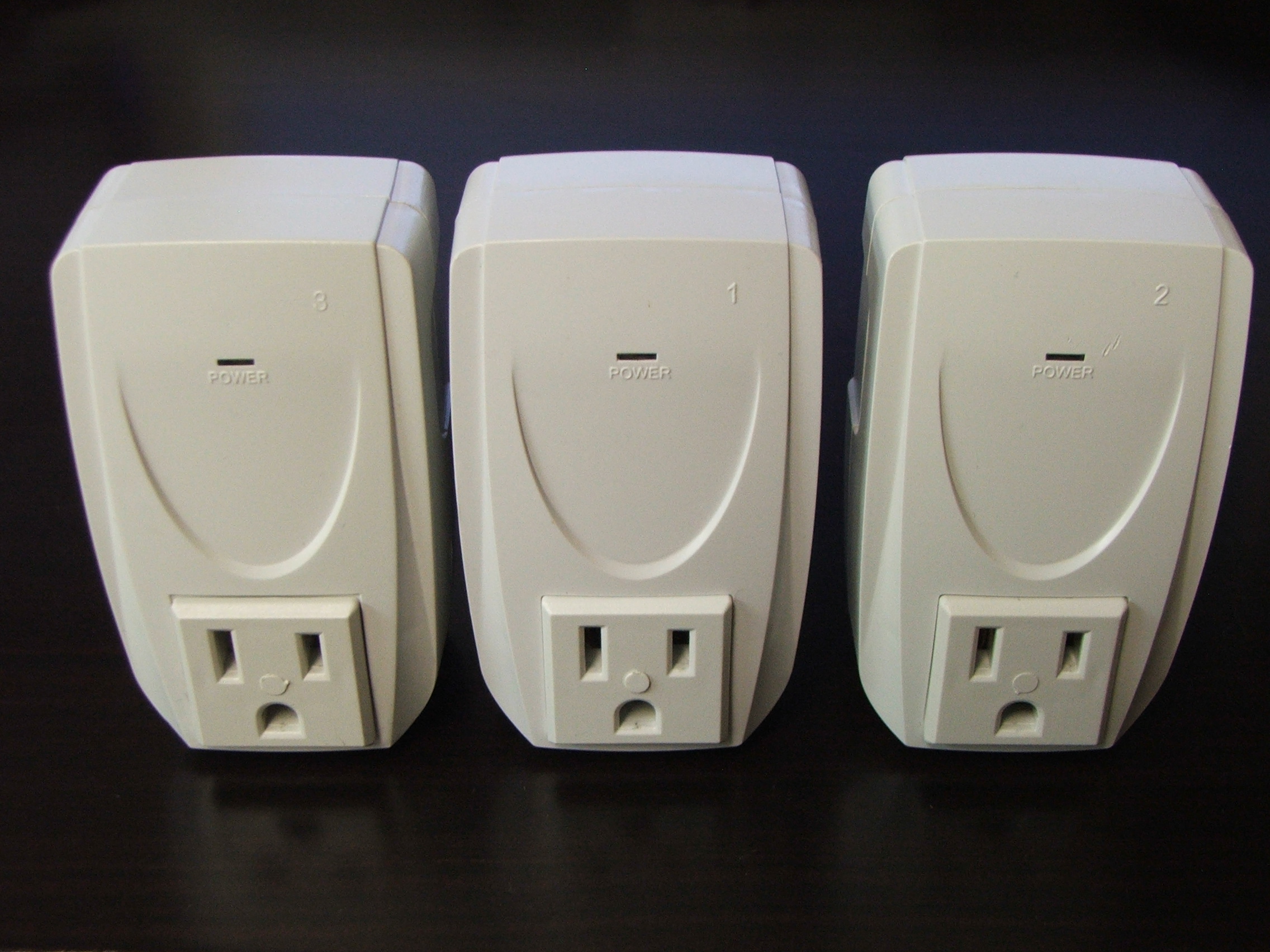
I found a cheap wireless remote control that controls three independent power sockets.
Using the transmitter circuit board and connecting it to a LaunchPad development board I was able to remotely control the three 110V sockets using a PC. The system can operate on four channels so it would be possible to operate 12 individual sockets; unfortunately I do not have enough IO pins on the LaunchPad but I will point out how this can be achieved.
Because the transmitter is wireless there is no need to go anywhere near the 110V circuitry so this is a safe hack even for someone with very little electronics experience.
I did not do this with any particular use in mind but you might use it for controlling Christmas lights, periodically turning on/off lamps in your house while on vacation etc.
Once you have the PC in charge it is also possible to control the sockets from an internet connection or mobile phone. See the last page on suggestion on how this might be achieved.
Hardware
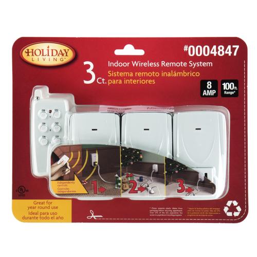
The hardware you will need for this hack is the Holiday Living 3 Ct. Indoor Wireless Remote System (http://www.lowes.com).
In addition you will need the Texas Instruments Launchpad development kit
(https://estore.ti.com/MSP-EXP430G2-MSP430-LaunchPad-Value-Line-Development-kit-P2031.aspx).
The remaining parts are
1N4001 diode
prototyping breadboard(s)
hookup wires
In addition you will need the Texas Instruments Launchpad development kit
(https://estore.ti.com/MSP-EXP430G2-MSP430-LaunchPad-Value-Line-Development-kit-P2031.aspx).
The remaining parts are
1N4001 diode
prototyping breadboard(s)
hookup wires
Preparing the Transmitter Board
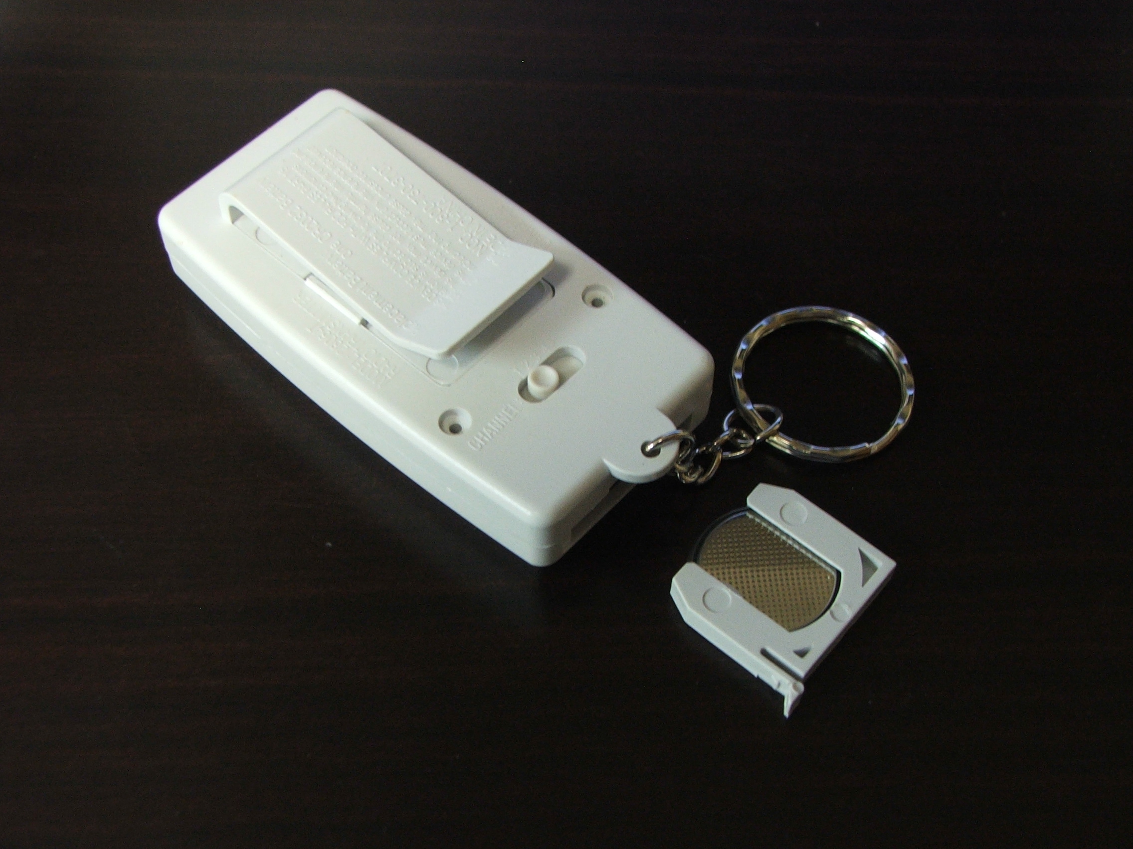
The first thing to do is to disassemble the remote transmitter
1. Remove the battery
2. Remove the two screws on the back of the case
3. Separate the two halves of the case
4. Remove the screw at the top of the circuit board
5. Remove the circuit board
6. Remove the channel switch (optional)
7. Unsolder the battery connectors
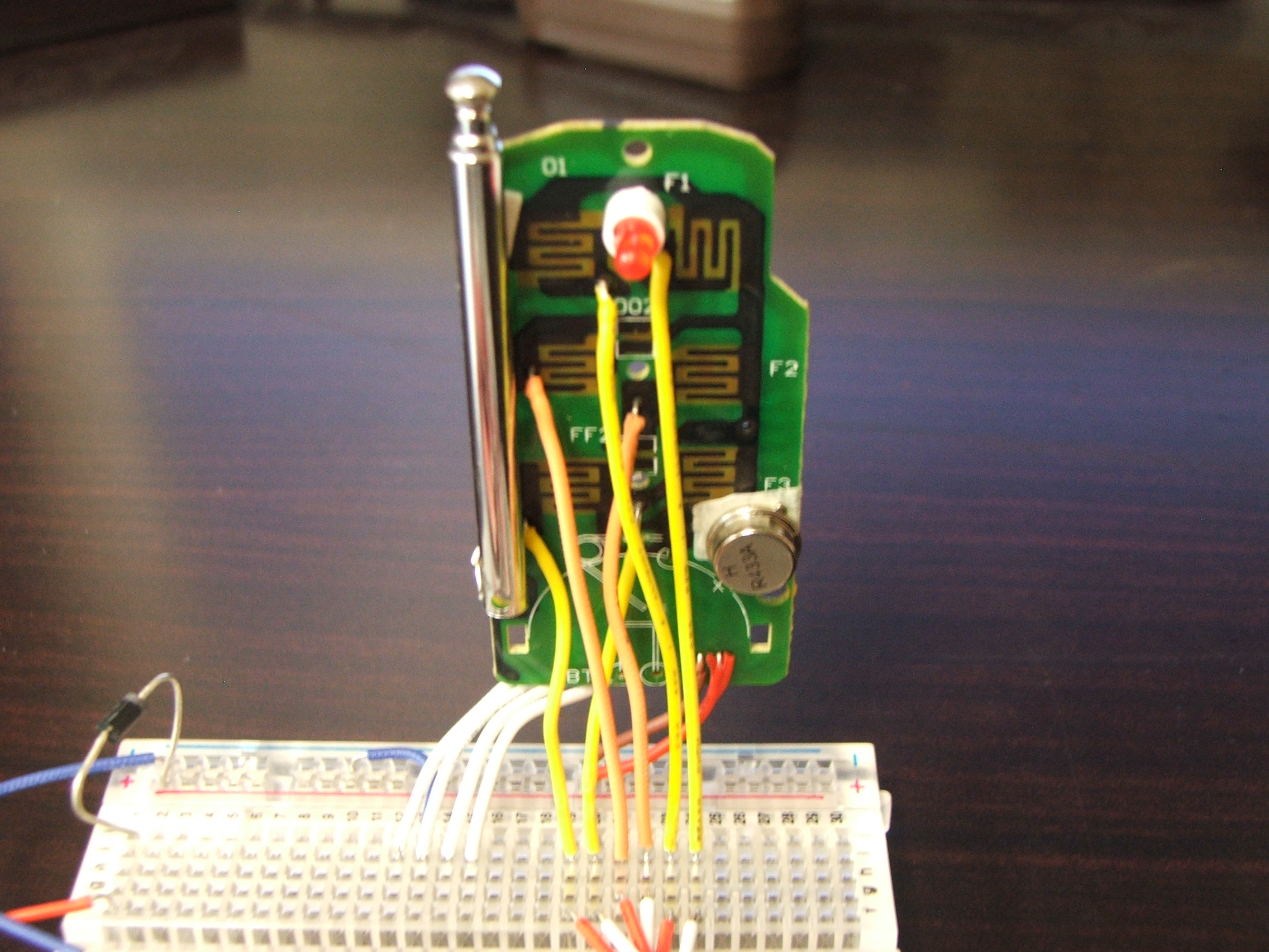
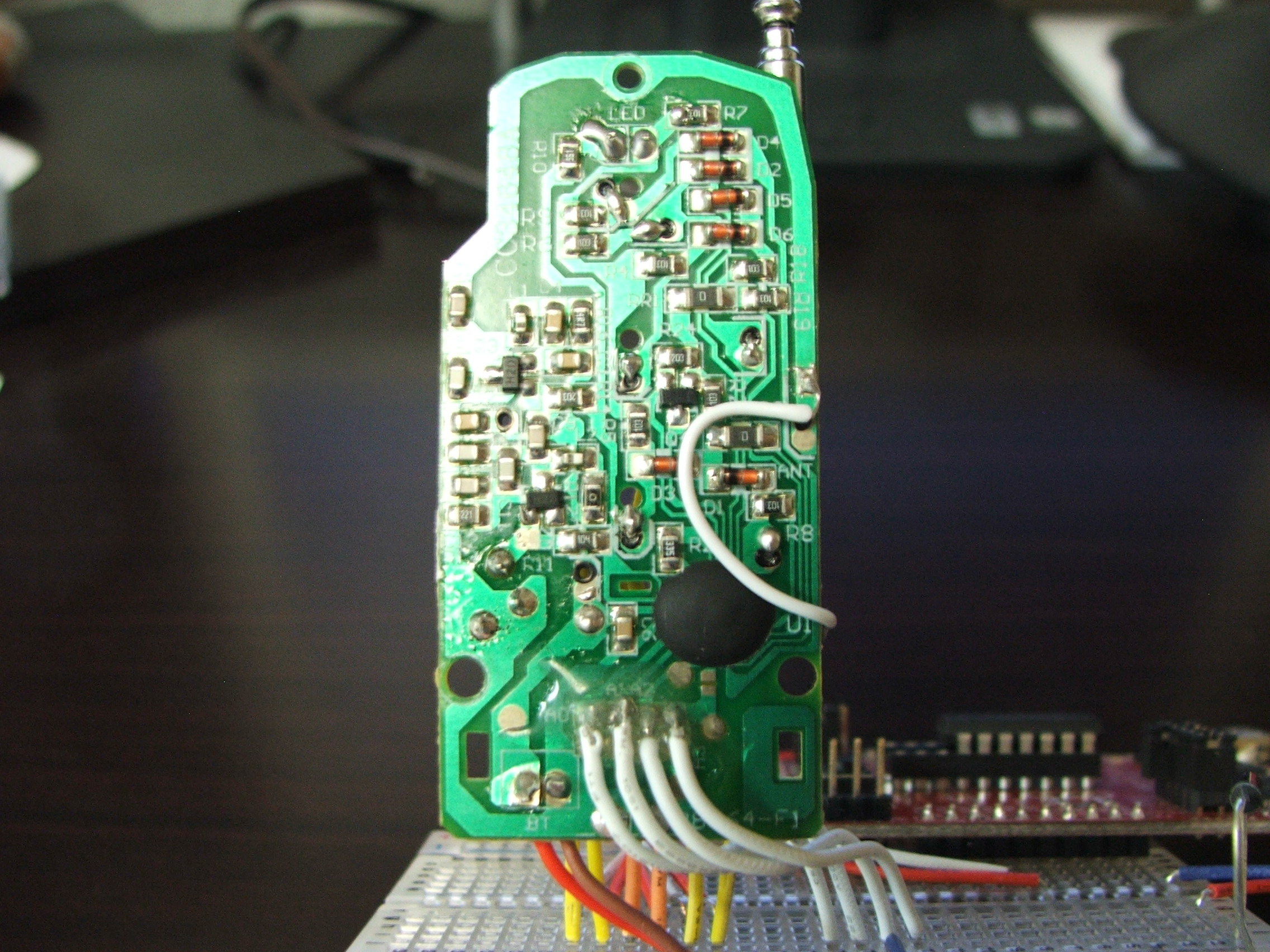
Next you need to add the power and control wires to the board
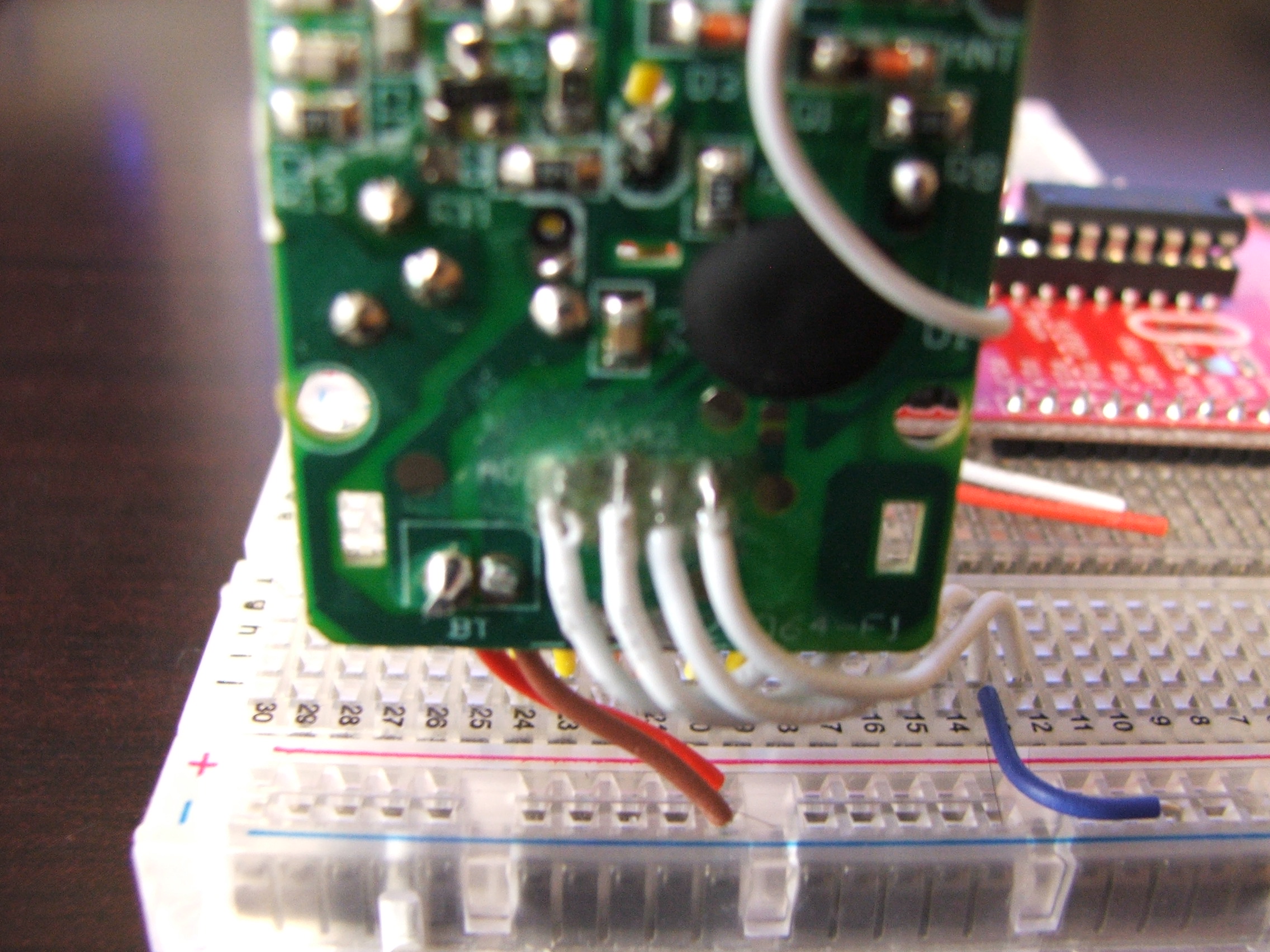
8. Solder wires for power connection - there are a pair of holes conveniently labelled BT just for this purpose
9. Attach wires to -ve side of each switch pad - each pad has a via that conveniently has a small solder pad next to it on the circuit side of the board. Make a small bend in the end of the wire, pass it through the via and solder it to the pad.
If you wish to break out the channel switch you can solder wires to the 4 small pads at the top of the switch. This is tricky and you need to be careful not to break off the track. Once the wires are attached I recommend using some epoxy to reinforce this area (see image).
1. Remove the battery
2. Remove the two screws on the back of the case
3. Separate the two halves of the case
4. Remove the screw at the top of the circuit board
5. Remove the circuit board
6. Remove the channel switch (optional)
7. Unsolder the battery connectors
Next you need to add the power and control wires to the board
8. Solder wires for power connection - there are a pair of holes conveniently labelled BT just for this purpose
9. Attach wires to -ve side of each switch pad - each pad has a via that conveniently has a small solder pad next to it on the circuit side of the board. Make a small bend in the end of the wire, pass it through the via and solder it to the pad.
If you wish to break out the channel switch you can solder wires to the 4 small pads at the top of the switch. This is tricky and you need to be careful not to break off the track. Once the wires are attached I recommend using some epoxy to reinforce this area (see image).
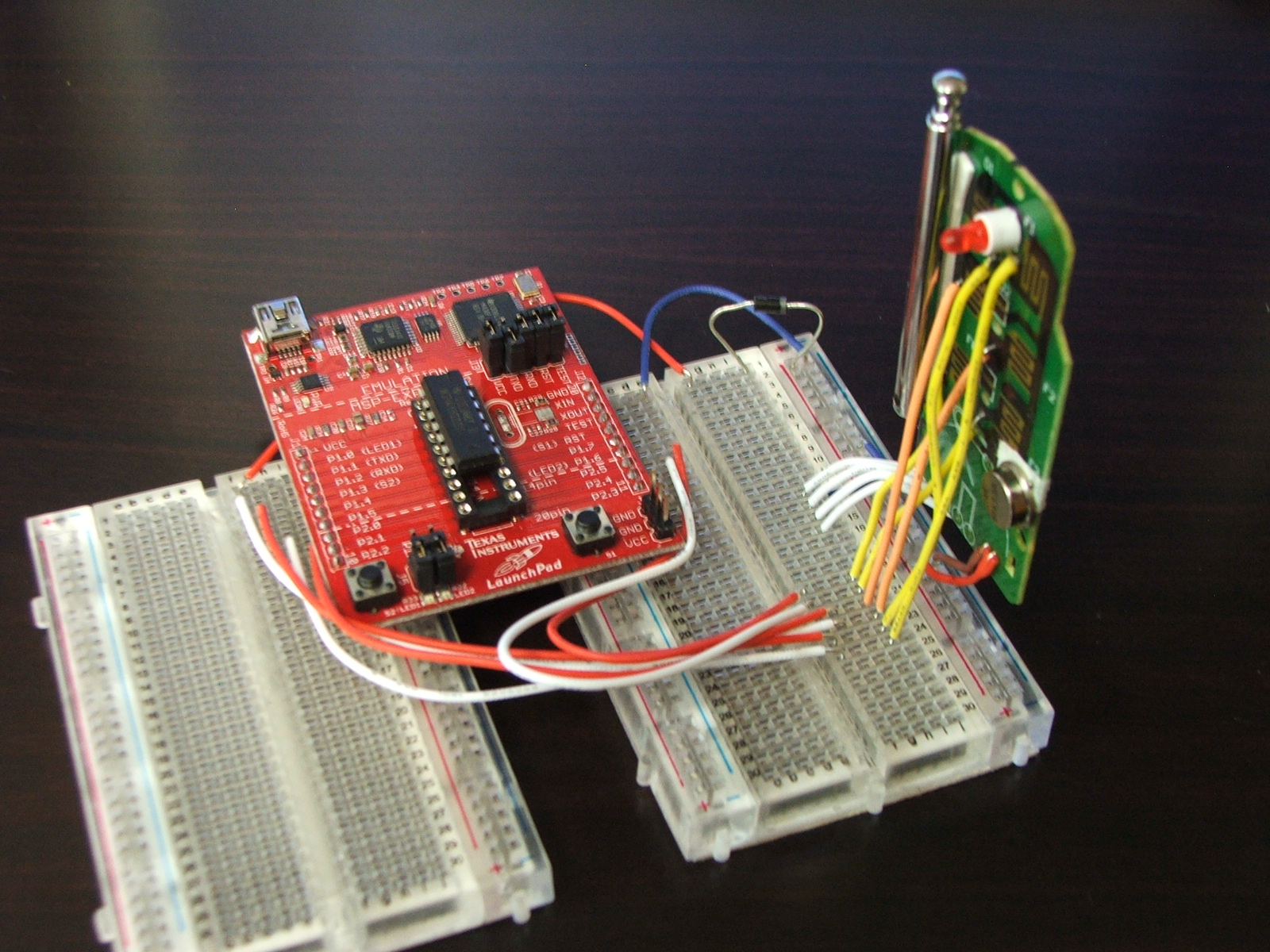
Wiring Up the Microprocessor
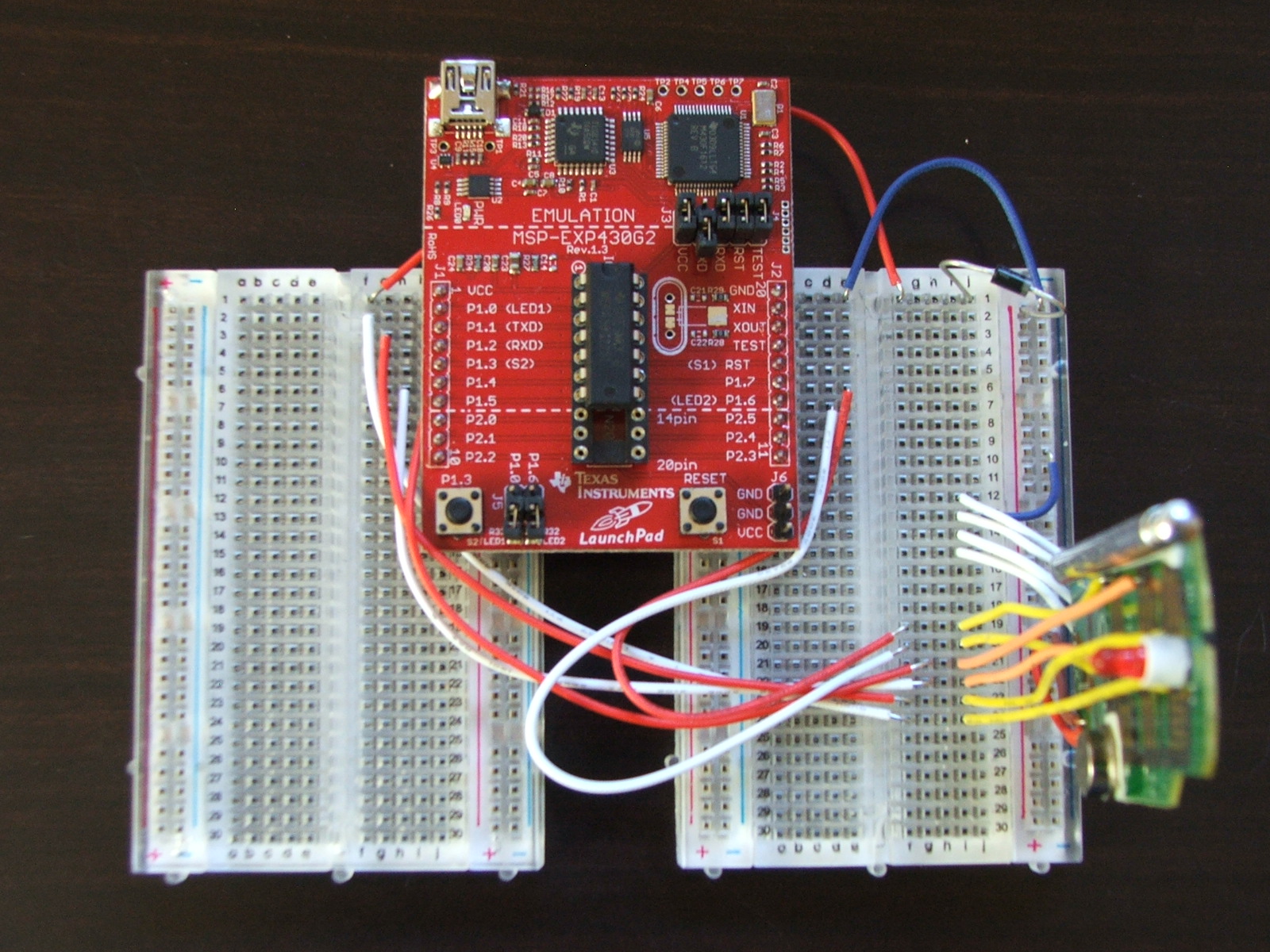
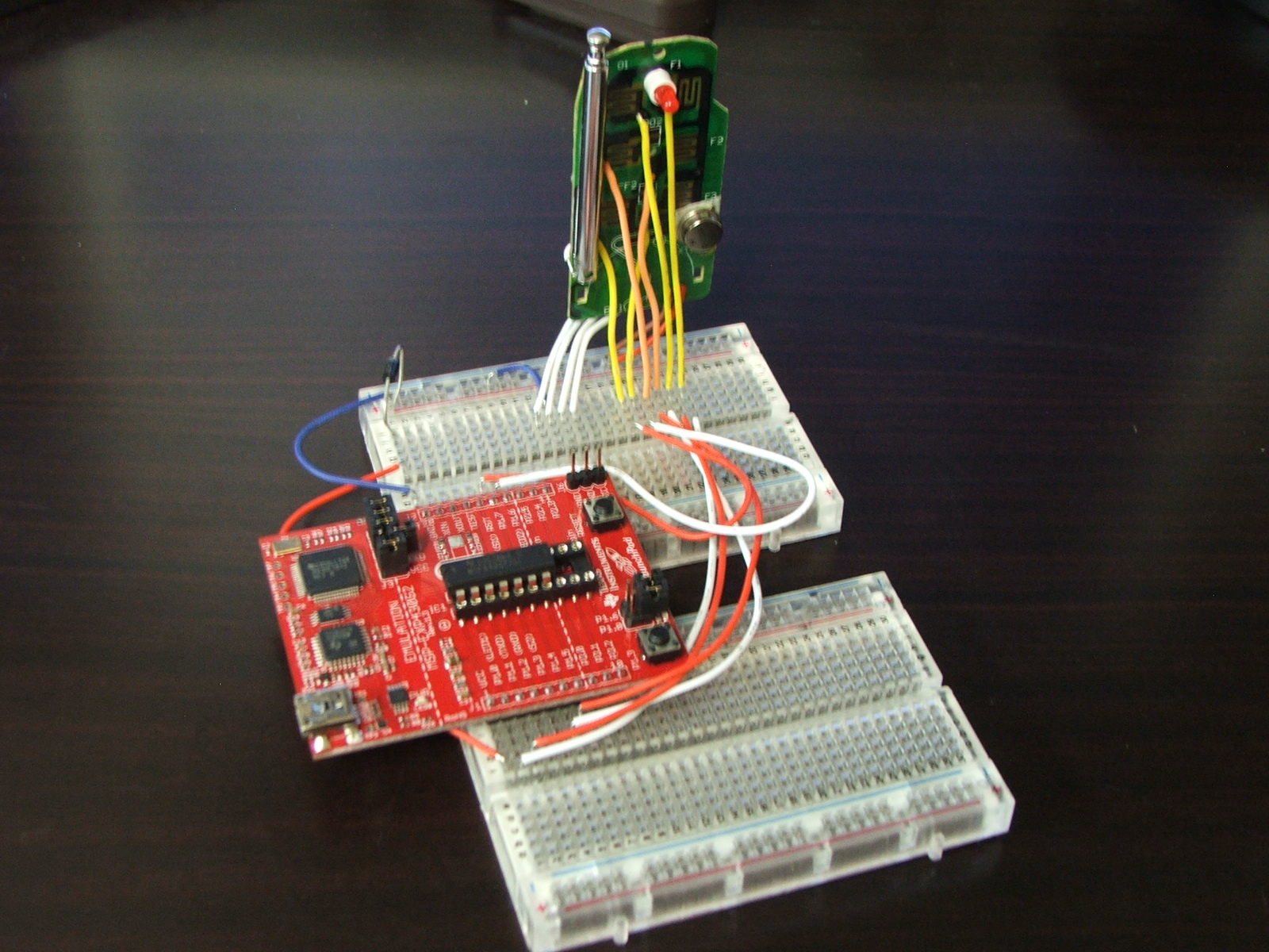
As you can see I have soldered header pins to my LaunchPad to allow it to be inserted into the breadboards.
The Launchpad supplies 3.6V when connected to the USB port of a computer. The remote only used a 3V battery so I added a diode to the Vcc line to step the power down.
Each of the 6 wires connected to the button pads needs to be connected to a pin of the mircoprocessor. Sending 3.6V to button pads does not appear to effect performance or damage the transmitter.
The order in which I connected the pins is
P1.0 - Receiver 1 - Off
P1.1 - Receiver 1 - On
P1.2 - Not connected (used for Rx line from PC)
P1.3 - Not connected (connected to switch on Launchpad)
P1.4 - Receiver 2 - Off
P1.5 - Receiver 2 - On
P1.6 - Receiver 3 - Off
P1.7 - Receiver 3 - On
In addition to configure the Launchpad I removed both jumpers from J5 (LEDs) and the TXD jumper from J3.
If you break out the channel switch you need to tie the appropriate channel wire to ground, the others can be left floating. If you wish you could control the channel from a microprocessor but the LaunchPad does not have enough IO lines for this without extra hardware.
Code
The code for the LaunchPad is attached. Hopefully you will find it well commented and easy to follow.
The UART receive code is interrupt driven . A high to low transition on Pin 1.2 starts the receive process. TIMERA is used to time each of the remaining bits; eight data bits and a stop bit.
The expected characters are as follows
'0' (0x30) - Receiver 1 off
'1' (0x31) - Receiver 1 on
'2' (0x32) - Receiver 2 off
'3' (0x33) - Receiver 2 on
'4' (0x34) - Receiver 3 off
'5' (0x35) - Receiver 3 on
The code then sets the appropriate button pin high, waits for a period of time to simulate a keypress and then resets all the button pad pins low.
The delay period will depend on the application. The delay in the code currently runs for about 1.5 seconds. I found this to be fairly reliable over a short range in ideal conditions. To guarantee that the appropriate socket turns on or off you might wish to increase the delay.
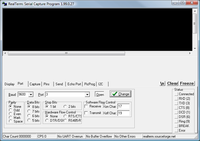
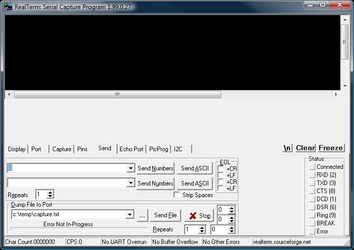
To control the transmitter simply attach the LaunchPad board to your computer using the USB port. Open you favourite terminal program and connect to COM3 at 9600,N,8,1. Send the appropriate ASCII character and watch the LED on the transmitter board flash to indicate that the command is being sent. If the receivers are plugged into a power outlet you will hear an audible click as the relay switches and any attached appliance will be switched on or off.
The UART receive code is interrupt driven . A high to low transition on Pin 1.2 starts the receive process. TIMERA is used to time each of the remaining bits; eight data bits and a stop bit.
The expected characters are as follows
'0' (0x30) - Receiver 1 off
'1' (0x31) - Receiver 1 on
'2' (0x32) - Receiver 2 off
'3' (0x33) - Receiver 2 on
'4' (0x34) - Receiver 3 off
'5' (0x35) - Receiver 3 on
The code then sets the appropriate button pin high, waits for a period of time to simulate a keypress and then resets all the button pad pins low.
The delay period will depend on the application. The delay in the code currently runs for about 1.5 seconds. I found this to be fairly reliable over a short range in ideal conditions. To guarantee that the appropriate socket turns on or off you might wish to increase the delay.
To control the transmitter simply attach the LaunchPad board to your computer using the USB port. Open you favourite terminal program and connect to COM3 at 9600,N,8,1. Send the appropriate ASCII character and watch the LED on the transmitter board flash to indicate that the command is being sent. If the receivers are plugged into a power outlet you will hear an audible click as the relay switches and any attached appliance will be switched on or off.
Downloads
Extensions
Now that we have a method of controlling the sockets from a PC it is not too complicated to write applications that allow for automated control from a PC or manual control via the internet or a mobile phone.
Attached is a simple piece of C# code that turns on all the receivers and then turns them off again.
For internet control you simply set up a listener on a fixed port. For a mobile phone the simplest method is to send a formatted email to an email account and have the application periodically check for new messages (POP3).
If anyone is interested in either of these application leave a comment and I will do a follow-up instructable.
Enjoy!