Control of Apc220 Modules With Smartphone and App
by CarlosVoltT in Circuits > Arduino
683 Views, 1 Favorites, 0 Comments
Control of Apc220 Modules With Smartphone and App
.png)
Controlling APC220 modules using a smartphone and an app involves a connection via a serial USB adapter to activate and control devices

More info and updates in https://rogerbit.com/wprb/2023/12/control-apc220-con-app/
Controlling APC220 modules using a smartphone and an app involves a connection via a serial USB adapter to activate and control devices such as lights, motors or other appliances.
APC220 modules are wireless communication devices that link with a USB serial adapter to allow connection to a smartphone. Using an application specifically designed to interact with these modules, users can control devices connected to the APC220 modules.
The app provides a user-friendly interface that allows setting up communication with APC220 modules. Users can send commands from their smartphone to turn on or off lights, activate motors or operate other devices connected to these modules.
The wireless connection between the smartphone and the APC220 modules via the USB serial adapter provides a convenient and efficient way to control devices remotely. This setup offers great potential for automating tasks, remotely controlling appliances, and creating versatile systems that can be easily activated or managed from a smartphone.
The APC220 module control system with a smartphone and an application, using a serial USB adapter, involves the use of a receiver that can be an Arduino Mini Pro. This Arduino Mini Pro acts as a receiver for the signals sent from the smartphone through of the APC220 modules.
The Arduino Mini Pro acts as the control center that receives instructions transmitted from the smartphone app via the APC220 modules connected through the USB serial adapter. The Arduino Mini Pro can interpret these signals and execute specific commands to turn on or off lights, activate motors, or operate other devices connected to it.
This combination of components—APC220 modules for wireless communication, a USB serial adapter to connect the modules to a smartphone, and an Arduino Mini Pro as a receiver—offers a flexible and versatile solution for remote device control. Users can take advantage of the app on their smartphone to send commands to the Arduino Mini Pro and thus control connected devices in real time from wherever they are.
Boards and modules used in this project
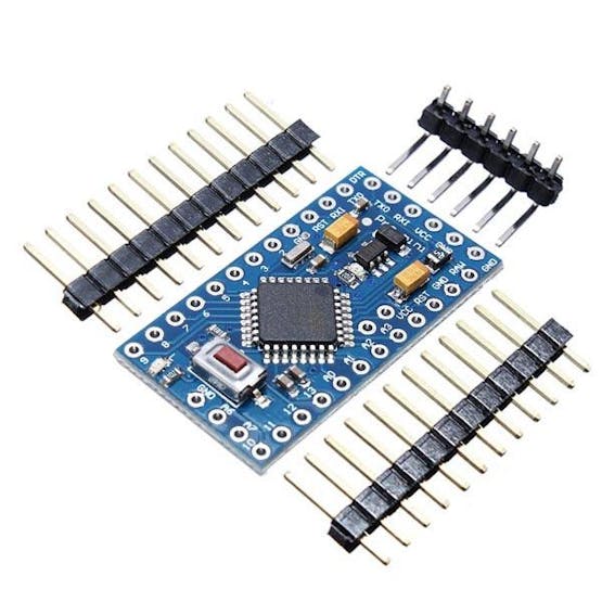
Arduino mini pro
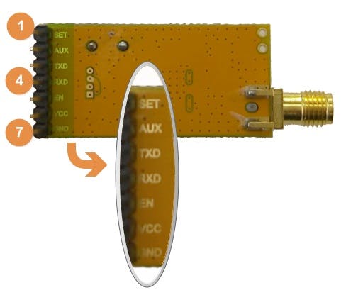
Apc220 module
The APC220 radio data module is a highly versatile, high-power radio solution, it is easy to configure and integrate into any project requiring a wireless RF link. It is perfect for robotic applications if you need wireless control. You can connect one of these modules with your MCU via TTL interface, and connect to your PC with another APC220 module via TTL/USB converter.
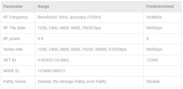
Specification
- Working frequency: 420 MHz to 450 MHz
- Power: 3.5-5.5V
- Current: <25-35mA
- Working temperature: -20°C~+70°C
- Range: 1200m line of sight (1200bps)
- Interface: UART/TTL
- Baud rate: 1200-19200 bps
- Baud rate (air): 1200-19200 bps
- Receive buffer: 256 bytes
- Size: 37mm × 17mm × 6.6mm
- Weight: 30g
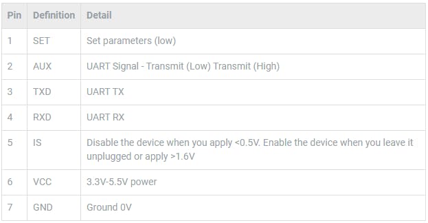
Pin Out
Download RF-Magic
Datasheet
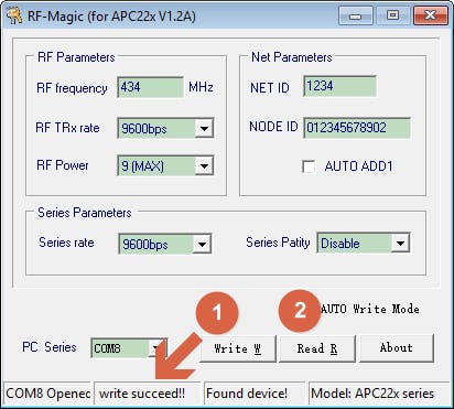
Run APC22X_V12A.exe (RF-Magic) as administrator if your system is not Windows XP.

NOTE : the software will recognize the APC220 module and COMX serial port automatically once we open it. Check in Device Manager to verify the correct COM port .
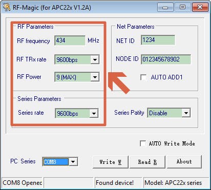
Configure RF-magic as in the red square frame below (default configuration), and click Write W to write your configuration, then click Read R to read the parameters you have set.
Setting
Write and read settings
Usb serial adapter
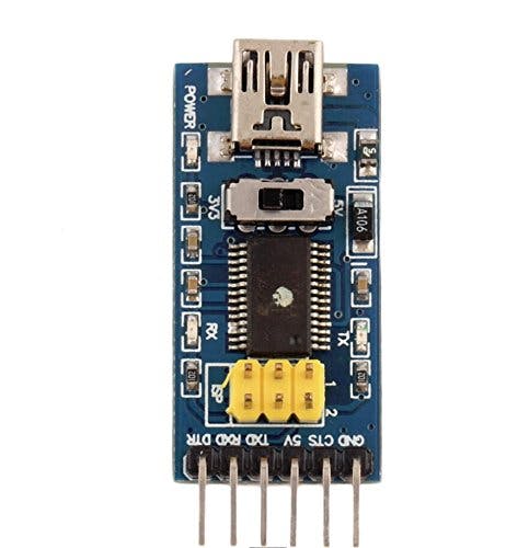
Description
FTDI Basic Program Downloader USB to TTL FT232RL 3.3V 5V DTR
This is a basic breakout board for the FTDI FT232RL USB to Serial IC. The pinout of this board matches the FTDI cable to work with official Arduino boards and cloned 5V Arduino boards. It can also be used for general serial applications. The main difference with this board is that it brings out the DTR pin instead of the RTS pin on the FTDI cable. The DTR pin allows an Arduino target to automatically reset when a new Sketch is downloaded. This is a really nice feature and allows a sketch to be downloaded without having to press the reset button. This board will automatically reset any Arduino board that has the reset pin on a 6 pin connector.
This board has TX and RX LEDs which make it a bit nicer to use over the FTDI cable. You can actually see the serial traffic on the LEDs to check if the board is working.
This board was designed to decrease the cost of Arduino development and increase ease of use (the auto reset feature is great!). Our Arduino Pro boards and LilyPads use this type of connector.
One of the nice features of this board is a jumper on the back of the board that allows the board to be configured to either 3.3V or 5V (both power output and I/O level). This board ships at 5V by default, but you can cut off the default trace and add a solder jumper if you need to switch to 3.3V.
CHARACTERISTICS
- Standard interface design, compatible with a variety of Arduinos such as the Pro Mini
- Original FTDI FT232 chip, stable performance
- With power indicator, send, receive, working status LED indicators
- With 3.3V and 5V TTL level supply options
- USB to serial TTL module, download STC SCM
- Mini USB port connection
- Standard interface, compliant with Arduino official controller; With power, sending, reviving indicator, With 3.3V / 5V power supply; Can be used as ordinary USB to serial TTL module, download STC singlechip
Hardware introduction
- Adopt FTDI company's FT232RL chip
- Lead out FT232RL chip all signal port, TTL / CMOS level
- RXD/TXD send-receive communication indicator
- USB power supply, can choose 5V or 3.3V interface level (if you need other level, can provide target voltage in VCC and GND pin)
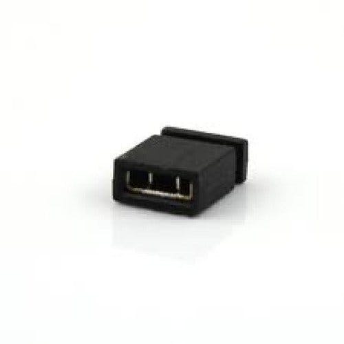
A Jumper
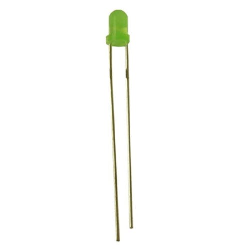
8 3mm LEDs
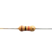
8 1KOhm resistors
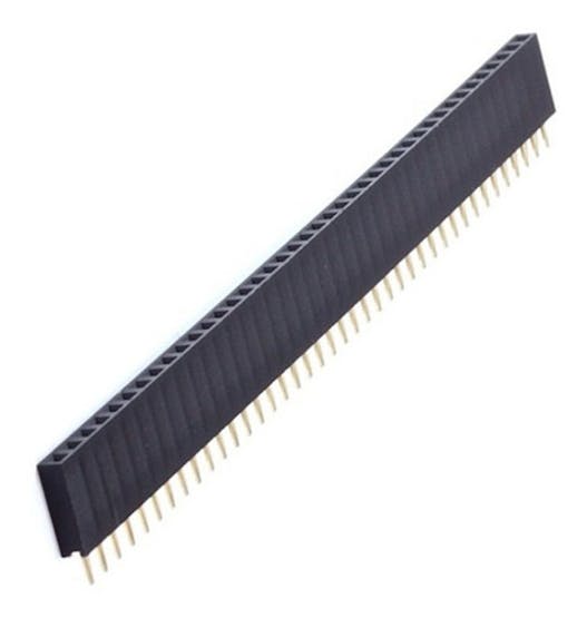
Female pins
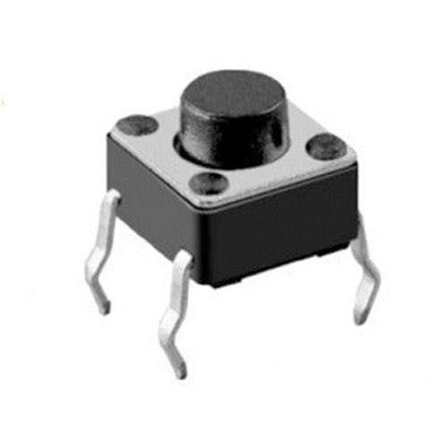
8 Push Buttons
Male pins

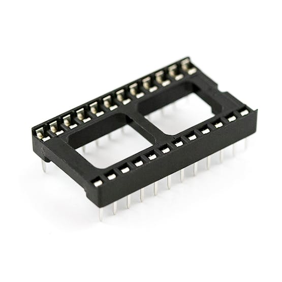
A socket for arduino mini pro
PCB
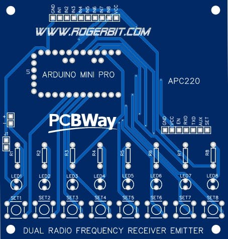
Download the free gerber file from here and send it to manufacture optionally–> https://www.pcbway.com/project/shareproject/Dual_Synchronized_Radio_Frequency_Control_for_Motor_Lights_and_more.html
App inventor
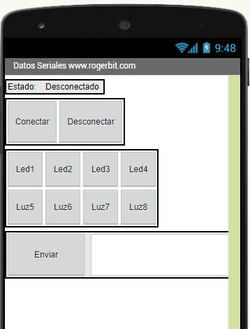
Download app and source file –> serial_app_ardu_radio