Control a Camera With an Arduino and RS232 Shield
by Maximous in Circuits > Arduino
27787 Views, 190 Favorites, 0 Comments
Control a Camera With an Arduino and RS232 Shield
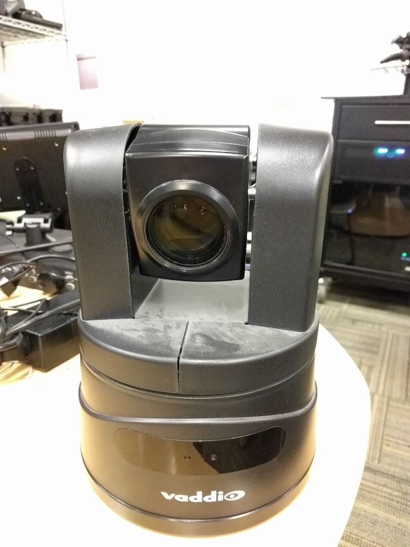
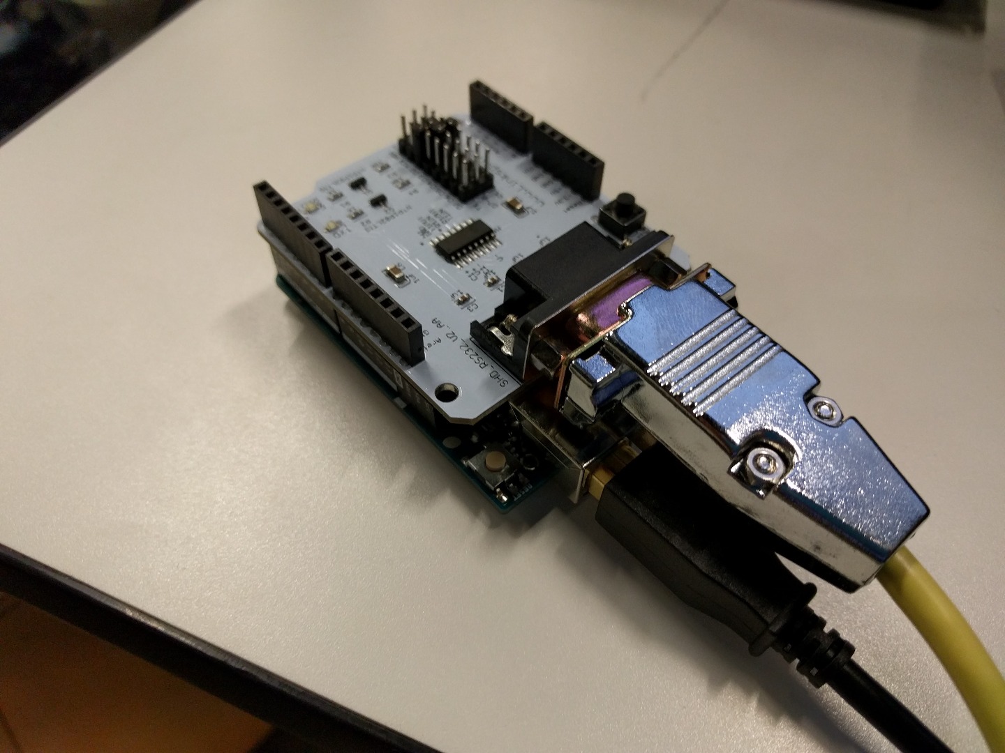
This tutorial will show you how you can control many different aspects of a cameras operation with an Arduino. These operation can be the pan and tilt of the camera, zoom and focus of the lens, and RGB characteristics. The Arduino will utilize an RS232 shield and send hexadecimal commands to the camera over an RJ45 cable.
Parts

Needed
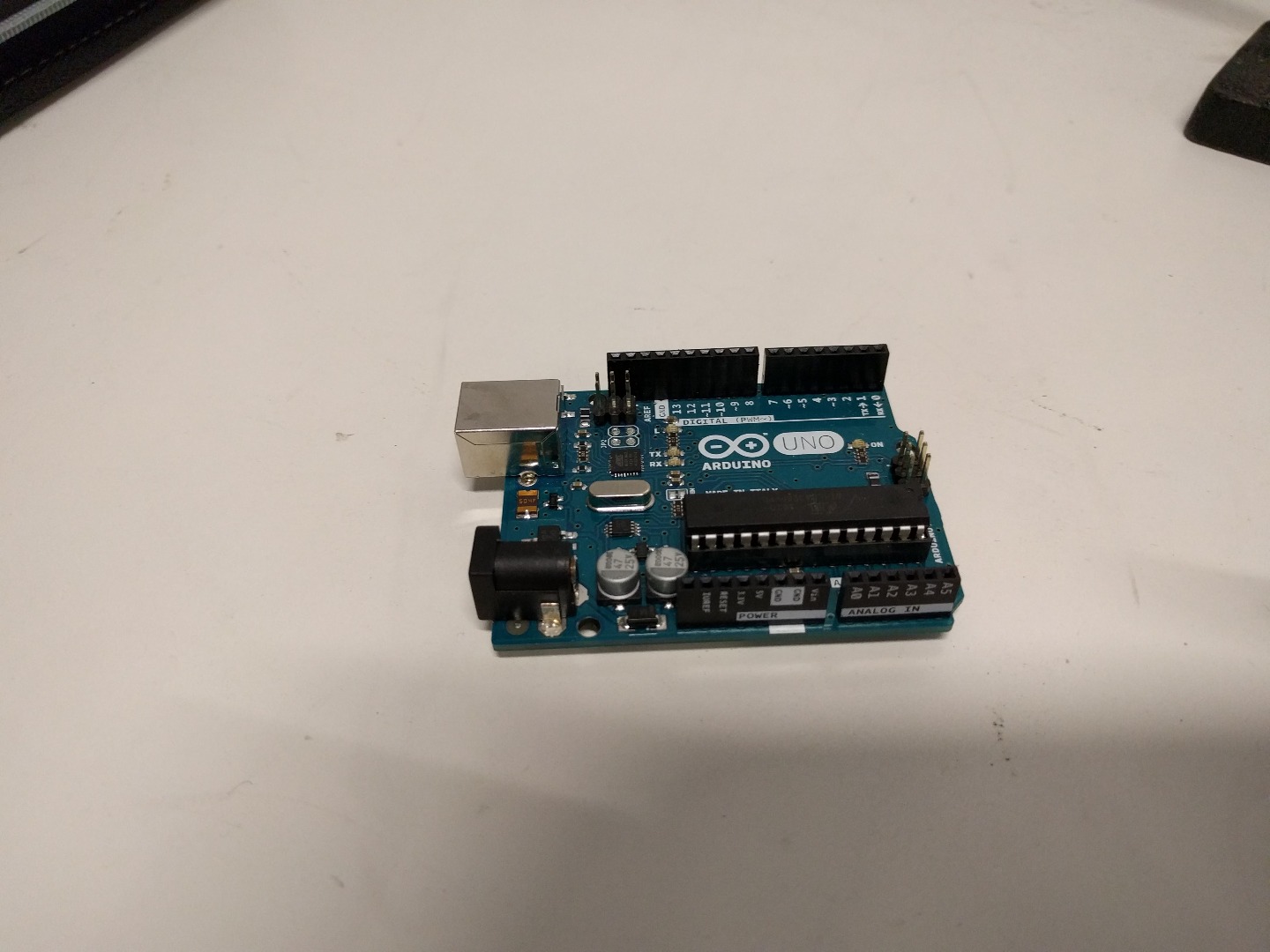
- Arduino Uno
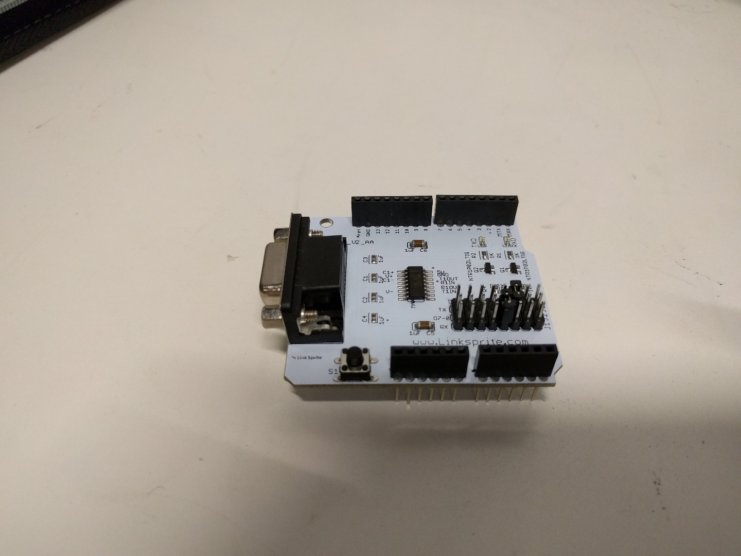
- RS232 Shield V2
- Camera (that accepts RS232 input)
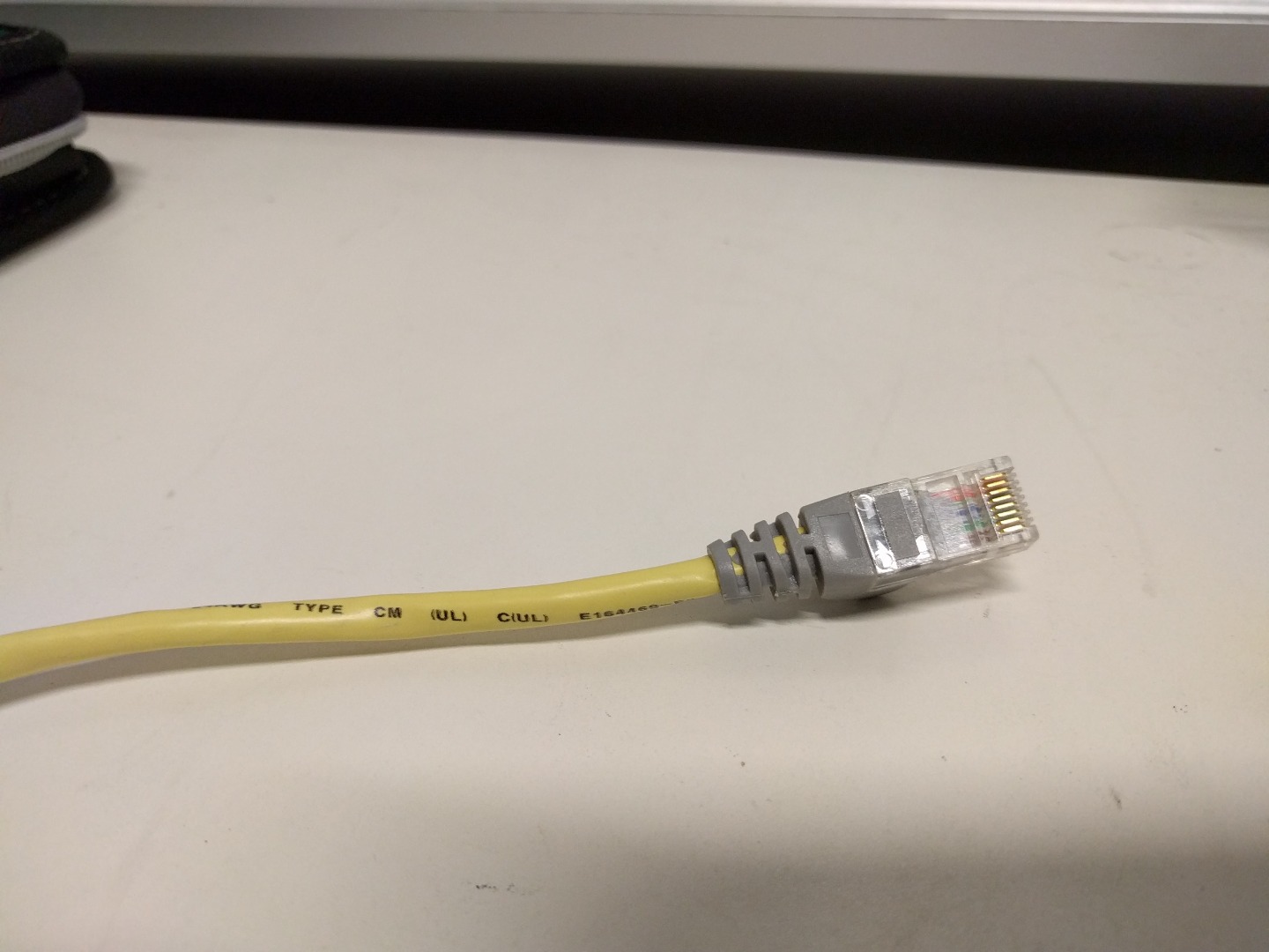
- RJ45 Cable
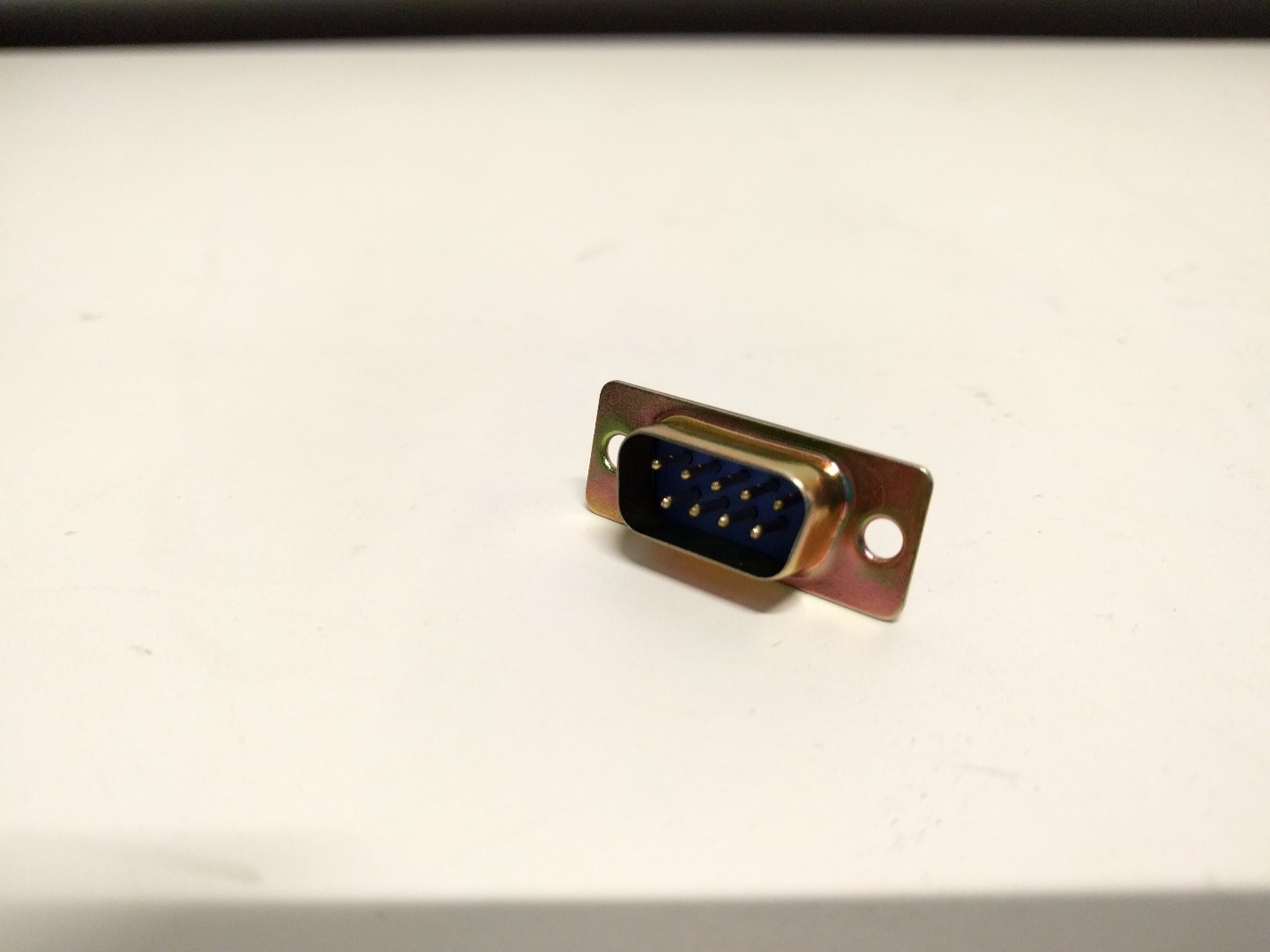
- 9 Pin Male D-Sub Connector (Solder Style)
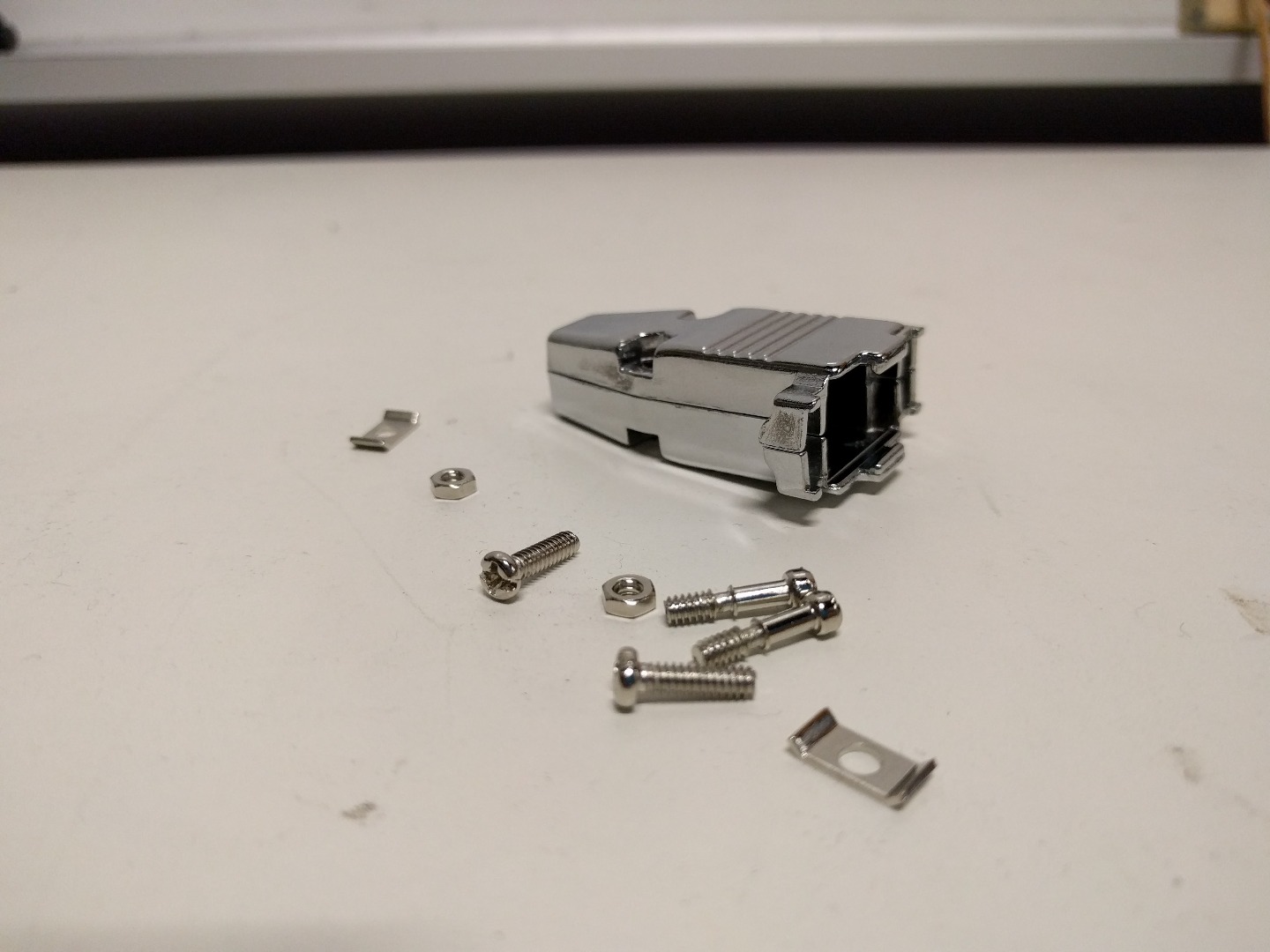
- 9 Pin D-Sub Connector Hood
Tools
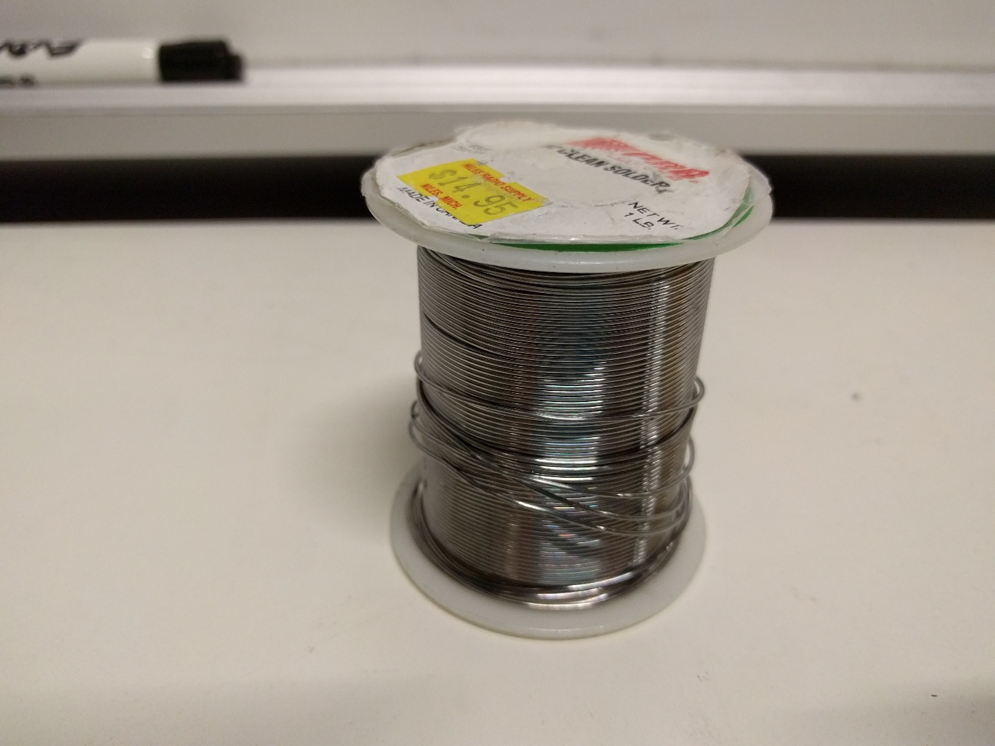
- Solder
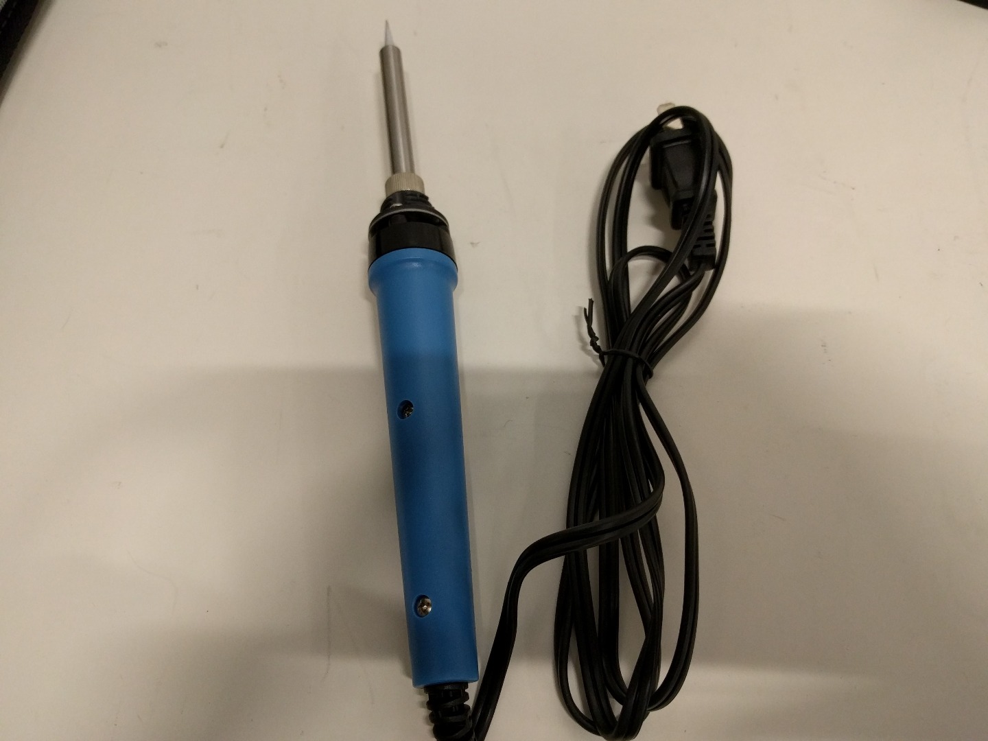
- Soldering Iron
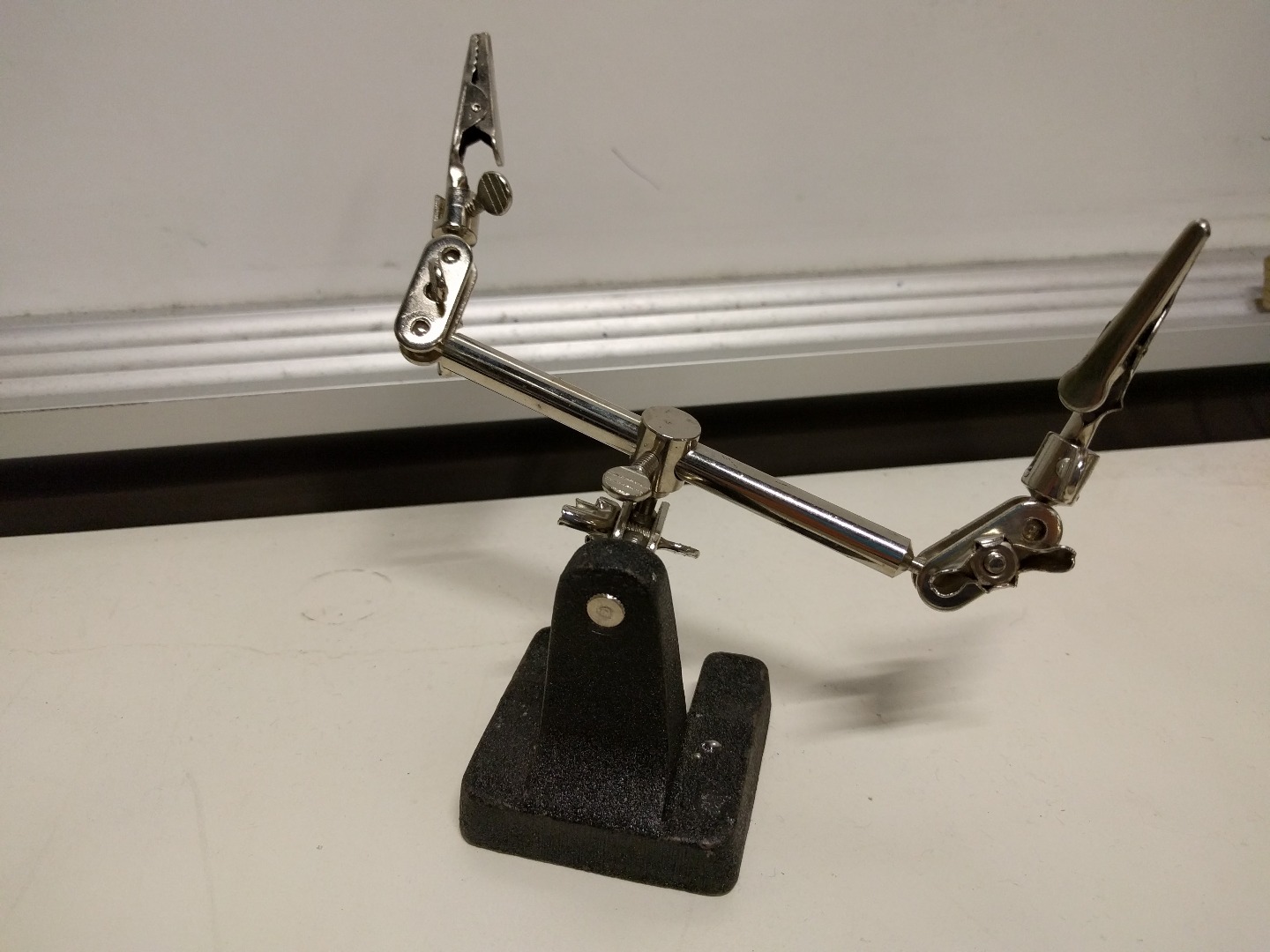
- 3rd Hand Tool
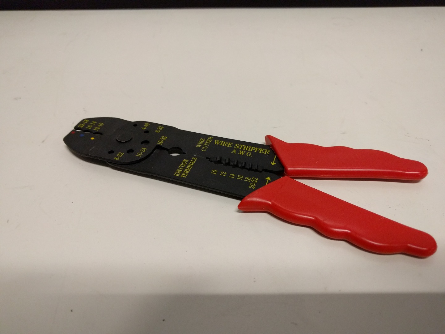
- Wire Cutters
Terminology
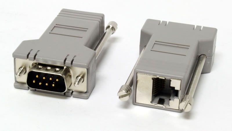
First, I think it will be helpful to define some terminology that will be used in this tutorial. Many of these words get thrown around interchangeably but there are subtle differences that can cause problems with a project.
RJ45 and Ethernet are NOT the same thing. RJ45 is the term used to represent the physical, wired connection while Ethernet is instead the protocol that is used when sending signals over a cable. Similarly, RS232 is the signaling protocol that is used to communicate with a piece of equipment.
A 9 Pin Connector or DB9 connector is the physical port that our RS232 Shield utilizes to send a signal. As it will be shown in this tutorial, the physical connection between two devices can be changed but the signaling method must stay the same. The camera we have has an input for an RJ45 cable but it utilizes RS232 signaling. For this reason we will splice one end of the ethernet cable and solder it onto a 9 Pin connector so that it can communicate with our RS232 Shield.
Baud rate is the rate at which information is sent over a serial connection. The standard baud rate is 9600 bits per second (bps).
*NOTE: Just because the camera accepts an RJ45 cable does NOT mean that you can use an Arduino Ethernet Shield. The camera requires RS232 signals and the Ethernet Shield is not designed for that protocol.
Make the Cable


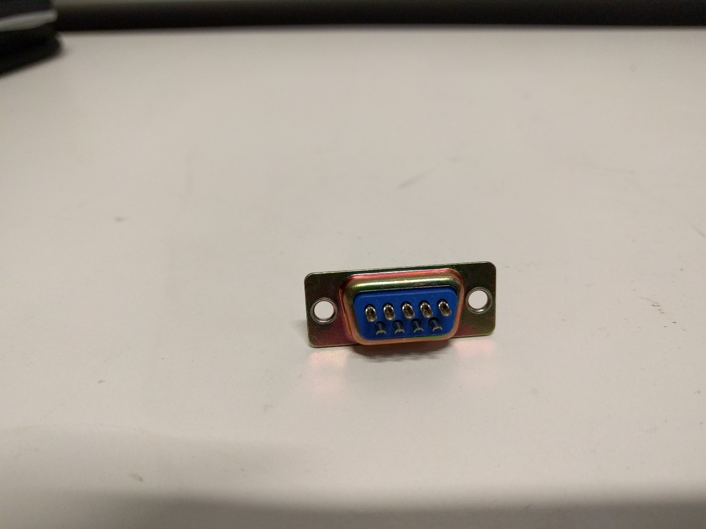
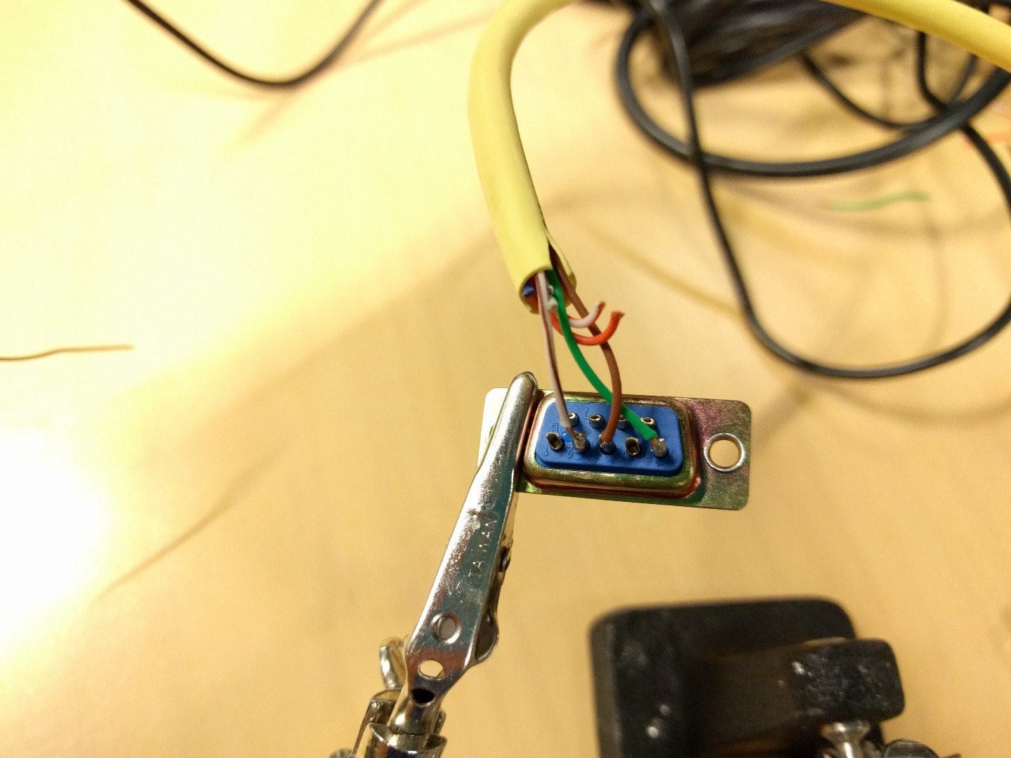
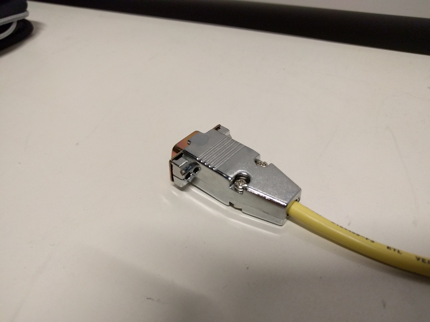
*NOTE: This step can be skipped all together if you use a DB9 to RJ45 converter. However, it can be cheaper (and more fun) to make your own.
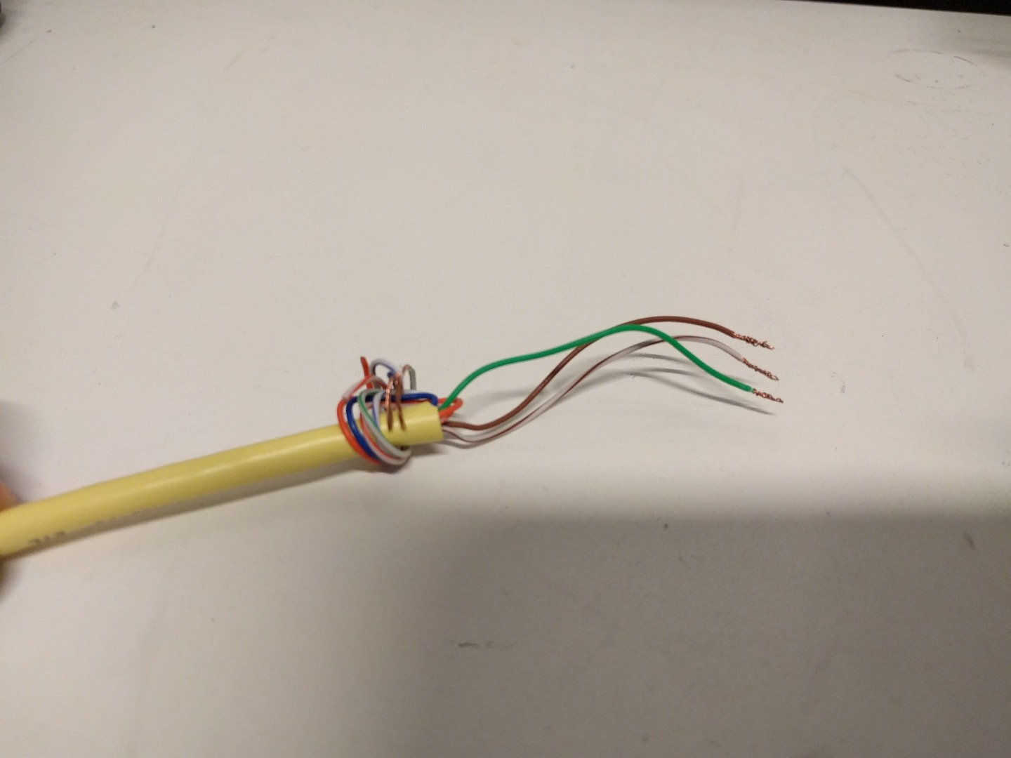
The first thing you will want to do is cut off the RJ45 connector at one end of your cable. Then strip away a couple inches of the outer rubber layer to expose the smaller wires inside. To make the wires easier to work with, it helps to untwist the smaller braids as well.
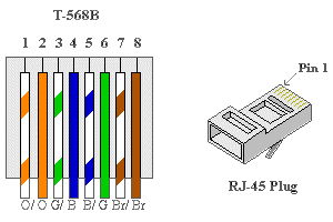
Now it is time to consult your camera's manual. The picture above shows the wiring diagram for the camera used in this tutorial. It can be seen that Pins 6, 7, and 8 are used for Ground, RXD, and TXD respectively. These are the only three pins we will need to use for this project. We next will consult the wiring diagram of our RJ45 cable. From this we can tell that we will be using the Green, Brown/White, and Brown wires because they correspond to pins 6, 7, and 8.
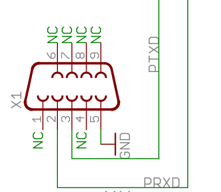
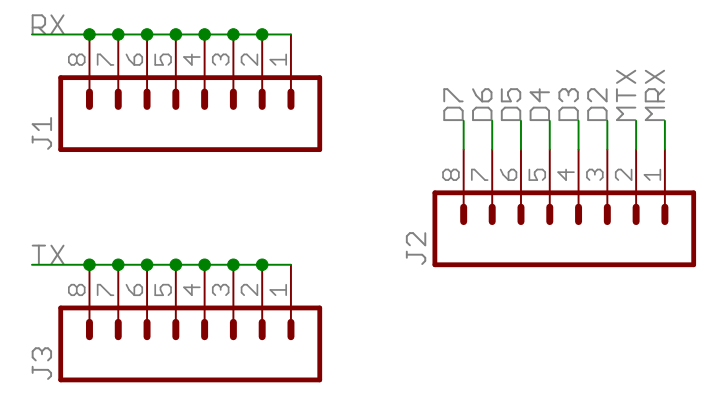
Next, we need to check the schematic of the RS232 shield. A section of the schematic has been added above for convenience. Locating the 9 Pin connector on the schematic, we see that pins 2, 3, and 5 are used for PRXD, TRXD, and Ground respectively. Normally the RX of one device will be connected to the TX of the other. However, in this instance the makers of the schematic labeled it "backwards" so that you will end up connected the PRXD from the shield to the RXD of the camera, and so on. If that still sounds confusing then follow the wiring diagram listed below:
- Green Wire --> Pin 5 (on 9 Pin Connector)
- Grown/White --> Pin 2 (on 9 Pin Connector)
- Brown --> Pin 3 (on 9 Pin Connector)
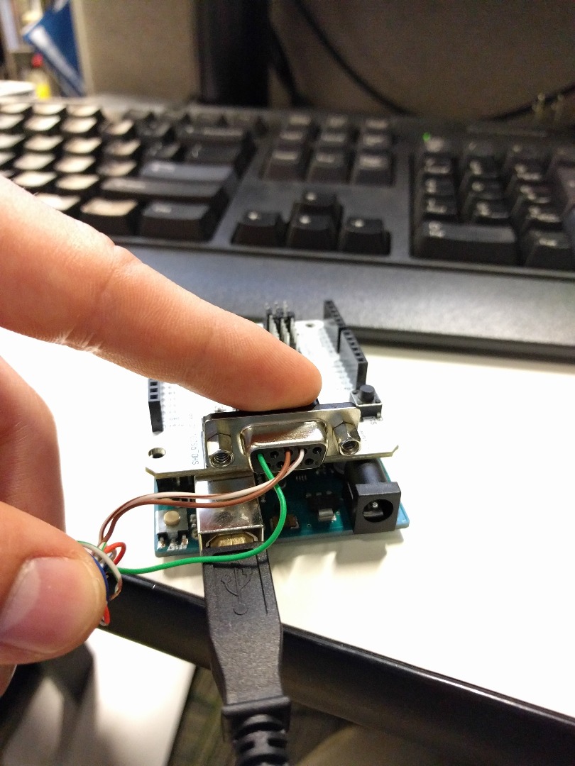
*Note: To ensure that you have the correct connection before soldering you can always plug the wires into the Female 9 Pin connector directly. If you have RX and TX reversed then nothing wrong will happen.
Solder these wires into their correct pin on the back of the 9 Pin Connector. If you look closely, there are small engravings on the connector itself which number the pins.
Once all the wires have been soldered on, place the connector inside the housing and screw it close. This housing helps protect the wires from short circuits and tension.
You now have your own DB9 to RJ45 connector!
Setting Up the System
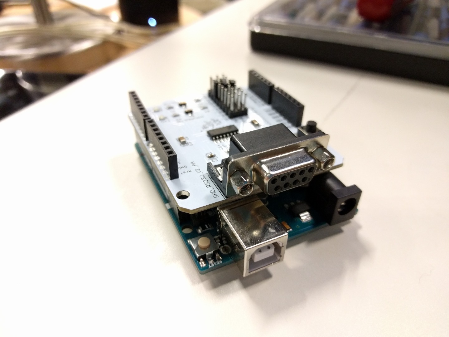
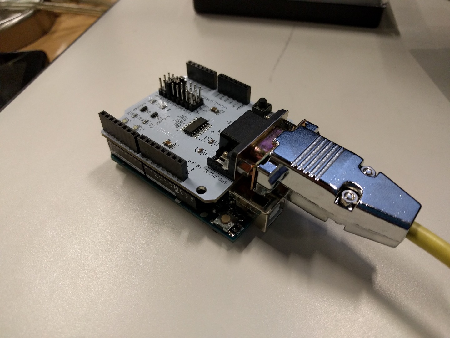

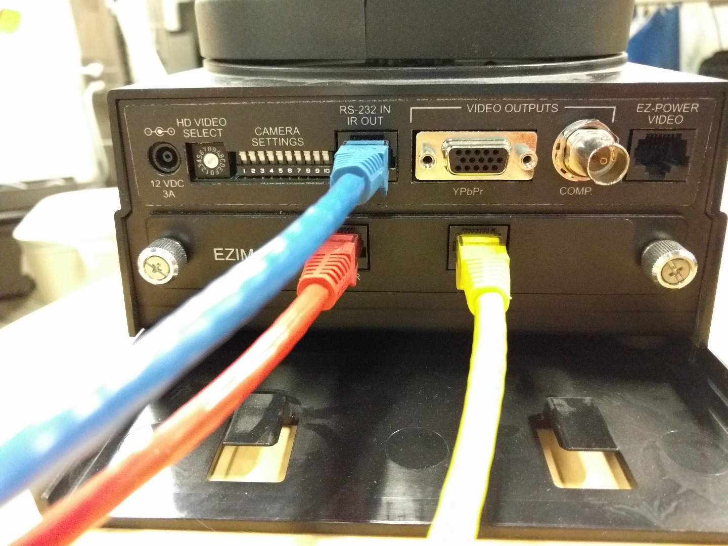
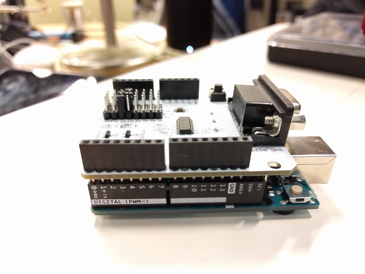
Now all you need to do is simply attach the RS232 shield to the top of the Arduino Uno. After that, plug in the power cable and the DB9 Cable to the Arduino and Shield respectively. Finally, plug in the other end of cable to the RJ45 port on your camera.
It is also important to change the jumpers on top of the RS232 shield as they are responsible for assigning a digital I/O pin to the TX and RX line. TX was chosen to be D2 and RX was chosen to be D3 (corresponds to which pins were chosen in the program). The default jumper locations are on MRX and MTX which correspond to digital pins 0 and 1. It is recommended that you not use the default pins because theses are the same pins that the computer talks to the Arduino with when uploading code. Due to that, you would need to unplug the shield from the Arduino every time you wanted to upload code. For convenience, we changed the pins to digital 2 and 3.
*NOTE: If there are more than one RJ45 ports on your device, make sure you are plugging it into the one that specifies it is used for RS232 signalling.
*NOTE: The cable shown in the RS232 port above is blue but the cable we made was yellow. This is due to the fact that we are working with an in-between signal transmitter that is not necessary for the project. Our yellow cable could also be plugged into the SAME port where the blue cable is currently plugged into.
Programming
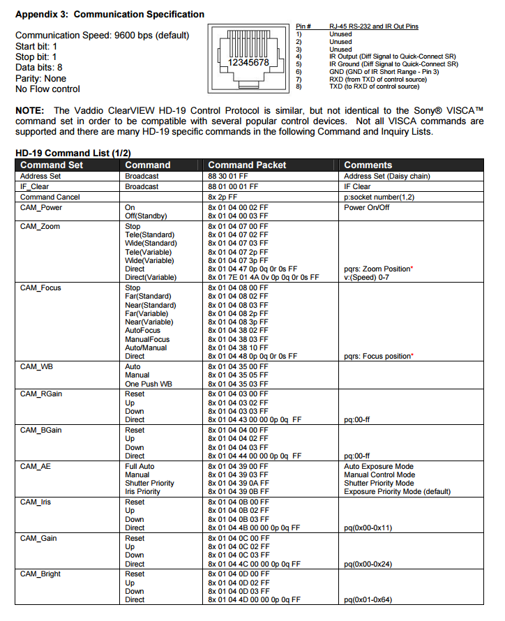
Many cameras that are operated by RS232 signaling use hexadecimal commands. These commands are sent to the camera as a series of hex bytes. A snapshot of the manual that lists a few of the commands is shown above.
A hex byte array is created for each command that you wish to use. When using the command it is important to match the baud rate of your device and send each byte in the array sequentially. From the manual it is seen that the baud rate is 9600 bps so that is what was specified in the code. It is also important to specify which ports you will be using for TX and RX. This is done when setting up a SoftwareSerial.
This example code below has the camera alternating between 2 predefined positions every five seconds.
// Serial Communication // October 29, 2015 // Purpose: Control the camera position using RS232 communications through a DB9 connector // with an attached RS232 Shield. // Status: WORKING
#include <SoftwareSerial.h>
// Do not use 0 and 1 if you want to be able to upload code while shield is attached to Arduino SoftwareSerial mySerial(2, 3); //2 is TX, 3 is RX
// Camera Commands // Default message 8x 01 04 3F 02 0p FF where x is camera number and p is preset number byte preset1[7] = {0x81, 0x01, 0x04, 0x3F, 0x02, 0x01, 0xFF}; // Camera 1 preset byte preset2[7] = {0x81, 0x01, 0x04, 0x3F, 0x02, 0x02, 0xFF}; // Camera 2 preset
byte address_command[4] = {0x88, 0x30, 0x01, 0xFF}; // Sets camera address (Needed for Daisy Chaining) byte if_clear[5] = {0x88, 0x01, 0x00, 0x01, 0xFF}; // Checks to see if communication line is clear
int delayTime = 500; //Time between commands
void setup() { Serial.begin(9600); // Serial Communication w/ Computer for Debugging mySerial.begin(9600); // Serial Communication w/ Camera
//Send Address command for (int i = 0; i < 4; i++) { mySerial.write(address_command[i]); Serial.println("Address Byte Sent"); }
delay(delayTime); //delay to allow camera time for next command
//Send IF_clear command for (int i = 0; i < 5; i++) { mySerial.write(if_clear[i]); Serial.println("If Clear Byte Sent"); } }
void loop() { for (int i = 0; i < (sizeof(preset1)); i++) // sizeof returns a count of bytes, not numbers if using int, float, or long { mySerial.write(preset1[i]); // sends each byte sequentially Serial.println("Camera Position 1 Byte Sent"); } delay(5000); // Waits for 5 seconds
for (int i = 0; i < (sizeof(preset2)); i++) // sizeof returns a count of bytes, not numbers if using int, float, or long { mySerial.write(preset2[i]); // sends each byte sequentially Serial.println("Set Camera Position 2 Byte Sent"); } delay(5000); }
The second example code allows you to control the direction in which the camera pans by sending it commands through the terminal window on your computer.
// Serial Communication // October 30, 2015 // Purpose: Control the camera position using keyboard inputs // Status: WORKING
#include <SoftwareSerial.h>
// Do not use 0 and 1 if you want to be able to upload code while shield is attached to Arduino SoftwareSerial mySerial(2, 3); //2 is TX, 3 is RX
// Camera Commands // Default message 8x 01 04 3F 02 0p FF where x is camera number and p is preset number byte preset1[7] = {0x81, 0x01, 0x04, 0x3F, 0x02, 0x01, 0xFF}; // Camera 1 preset byte preset2[7] = {0x81, 0x01, 0x04, 0x3F, 0x02, 0x02, 0xFF}; // Camera 2 preset
// Camera Controls byte panLeft[9] = {0x81, 0x01, 0x06, 0x01, 0x09, 0x09, 0x01, 0x03, 0xFF}; // Pan Camera Left byte panRight[9] = {0x81, 0x01, 0x06, 0x01, 0x09, 0x09, 0x02, 0x03, 0xFF}; // Pan Camera Right byte panUp[9] = {0x81, 0x01, 0x06, 0x01, 0x09, 0x09, 0x03, 0x01, 0xFF}; // Pan Camera Up byte panDown[9] = {0x81, 0x01, 0x06, 0x01, 0x09, 0x09, 0x03, 0x02, 0xFF}; // Camera Pan Down byte panStop[9] = {0x81, 0x01, 0x06, 0x01, 0x09, 0x09, 0x03, 0x03, 0xFF}; // Camera Pan Down
byte address_command[4] = {0x88, 0x30, 0x01, 0xFF}; // Sets camera address (Needed for Daisy Chaining) byte if_clear[5] = {0x88, 0x01, 0x00, 0x01, 0xFF}; // Checks to see if communication line is clear
int delayTime = 500; //Time between commands
void setup() { Serial.begin(9600); // Serial Communication w/ Computer for Debugging mySerial.begin(9600); // Serial Communication w/ Camera
//Send Address command for (int i = 0; i < 4; i++) { mySerial.write(address_command[i]); }
delay(delayTime); //delay to allow camera time for next command
//Send IF_clear command for (int i = 0; i < 5; i++) { mySerial.write(if_clear[i]); }
Serial.print("Please Input Commands"); }
void loop() { // Checks for serial input from terminal if (Serial.available() > 0) { char inChar = Serial.read(); // read incoming serial data: if (inChar == '1') // Camera Preset 1 { for (int i = 0; i < (sizeof(preset1)); i++) { mySerial.write(preset1[i]); // sends each byte sequentially } }
else if (inChar == '2') // Camera Preset 1 { for (int i = 0; i < (sizeof(preset2)); i++) { mySerial.write(preset2[i]); } }
else if (inChar == 'w') // Pan Camera Up { for (int i = 0; i < (sizeof(panUp)); i++) { mySerial.write(panUp[i]); } }
else if (inChar == 'a') // Pan Camera Left { for (int i = 0; i < (sizeof(panLeft)); i++) { mySerial.write(panLeft[i]); } }
else if (inChar == 's') // Pan Camera Down { for (int i = 0; i < (sizeof(panDown)); i++) { mySerial.write(panDown[i]); } }
else if (inChar == 'd') // Pan Camera Right { for (int i = 0; i < (sizeof(panRight)); i++) { mySerial.write(panRight[i]); } }
else if (inChar == 'q') // Stop Camera Pan { for (int i = 0; i < (sizeof(panStop)); i++) { mySerial.write(panStop[i]); } } } }
What's Next?
Now that you have control over many aspects of your camera (zoom, pan, power, etc.), the possibilities are endless. Some ideas for future projects may include:
- Adding an IR sensor and have a motion detecting camera
- Add an Ethernet shield and be able to control the cameras position over the internet
- Utilize the camera as a baby or pet monitor
- See what other devices you can connect to with RS232 signaling