Control Servo Motor Using Potentiometer
by CodeChamp in Circuits > Electronics
7473 Views, 30 Favorites, 0 Comments
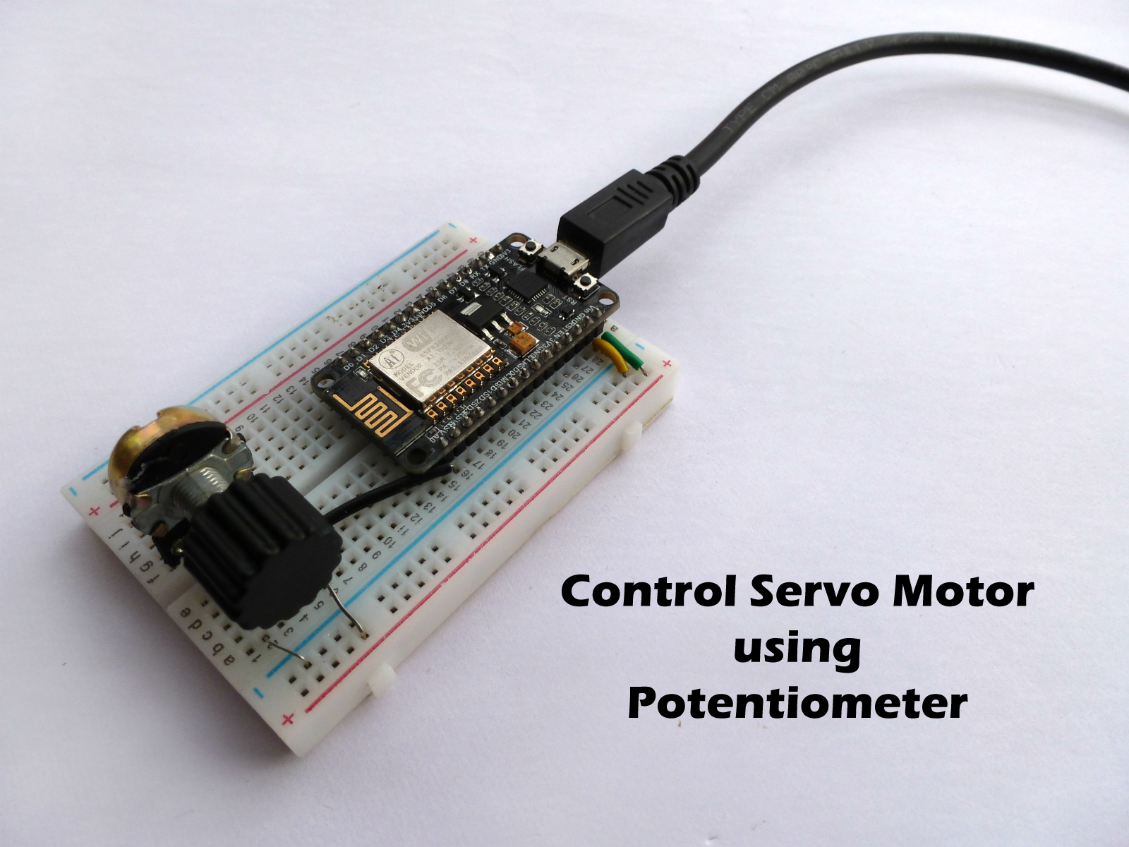
Control Servo Motor Using Potentiometer
Hello Makers,
This Instructable is part of a series of Instructables with the NodeMCU, my previous Instructables shows you how to Interfacing Servo with NodeMCU and lots more. So make sure, you check that first before trying out this. So, let's get started !!
Components Needed
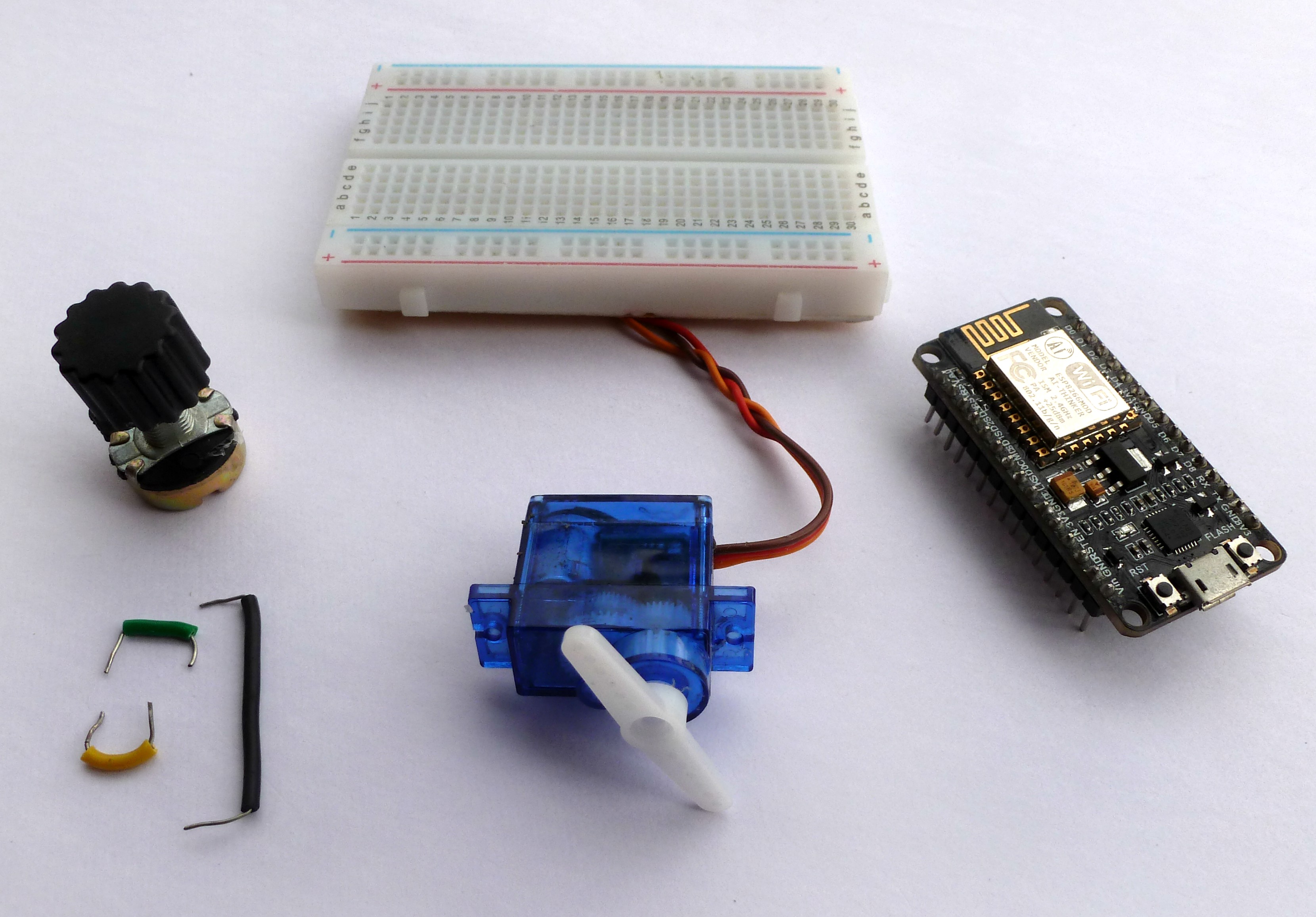
All that you need is:
Hardware Required
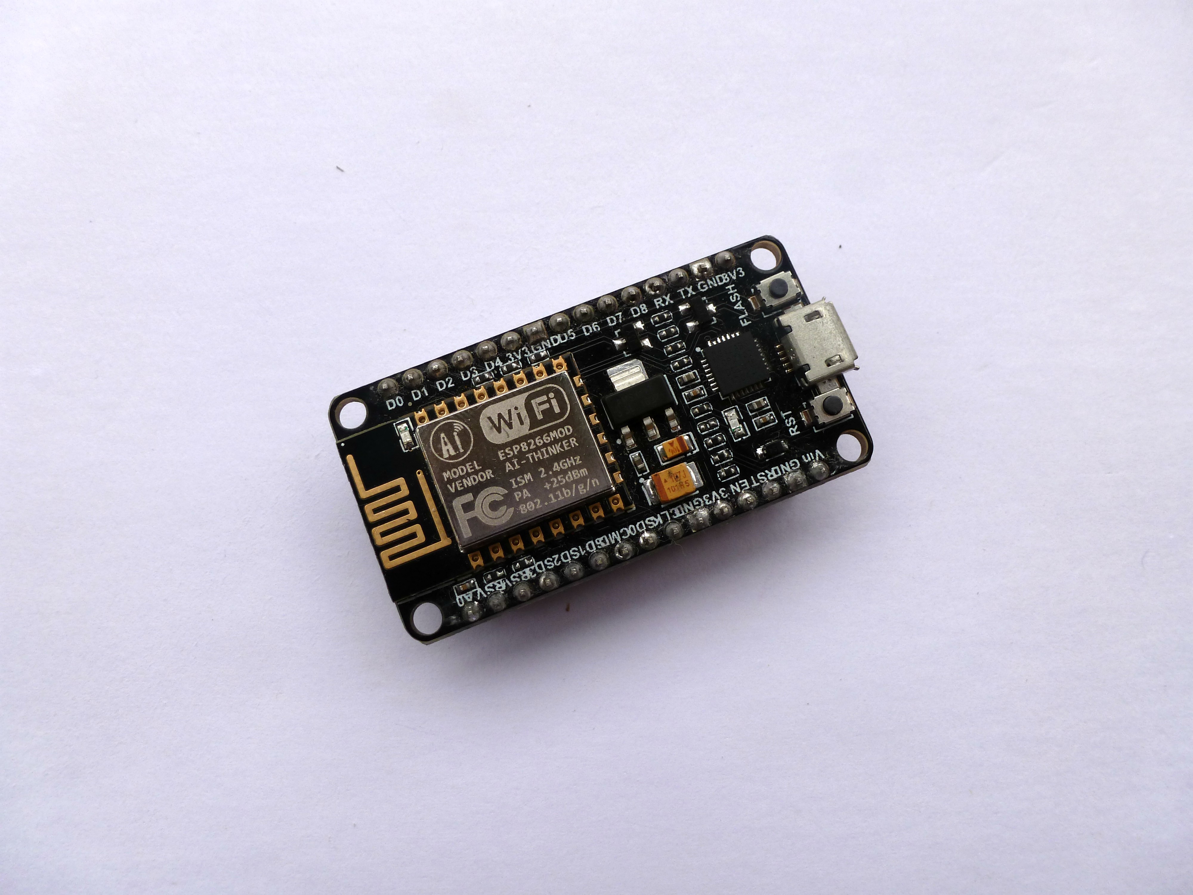
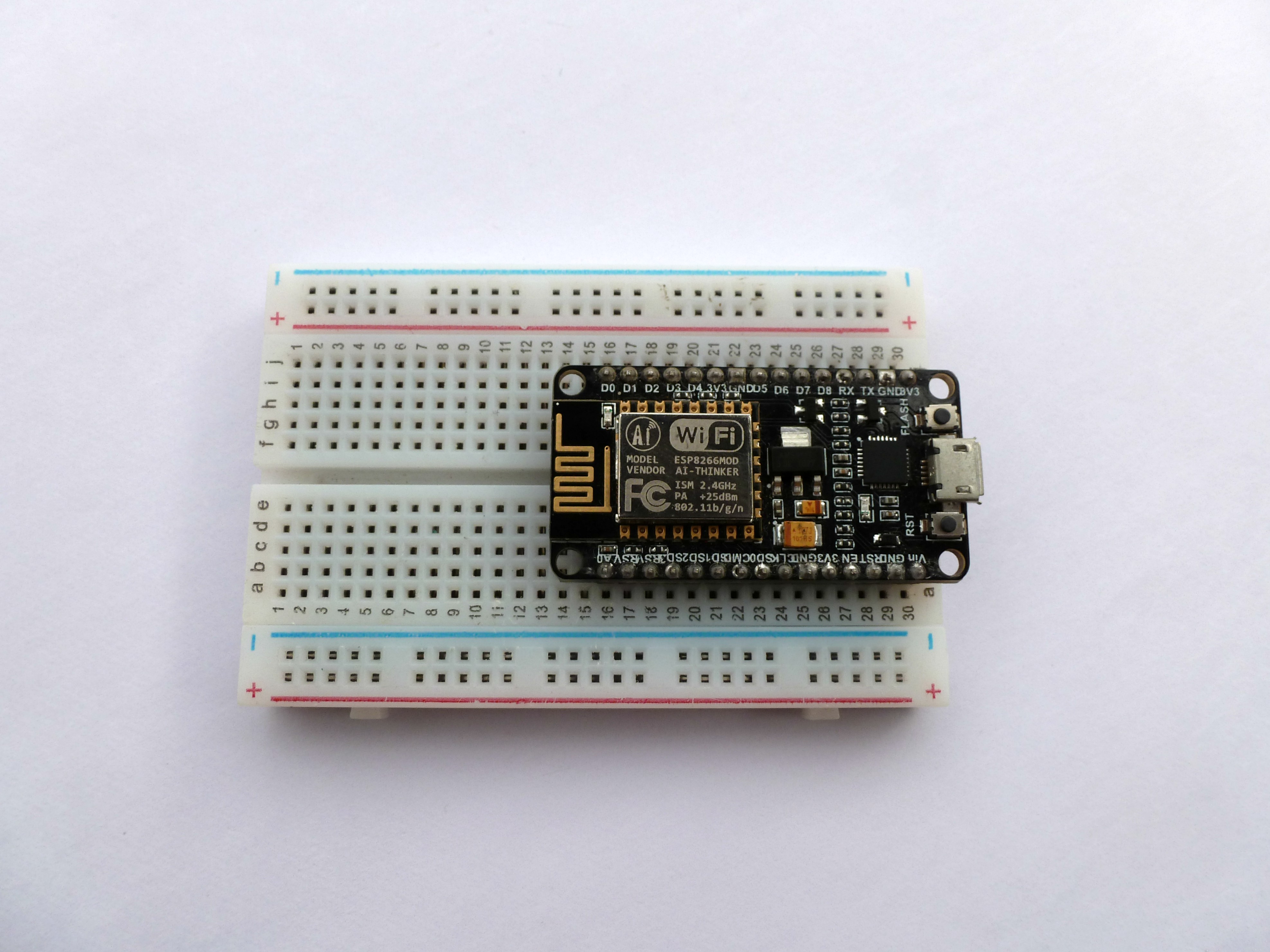
- NodeMCU
- 10K POT
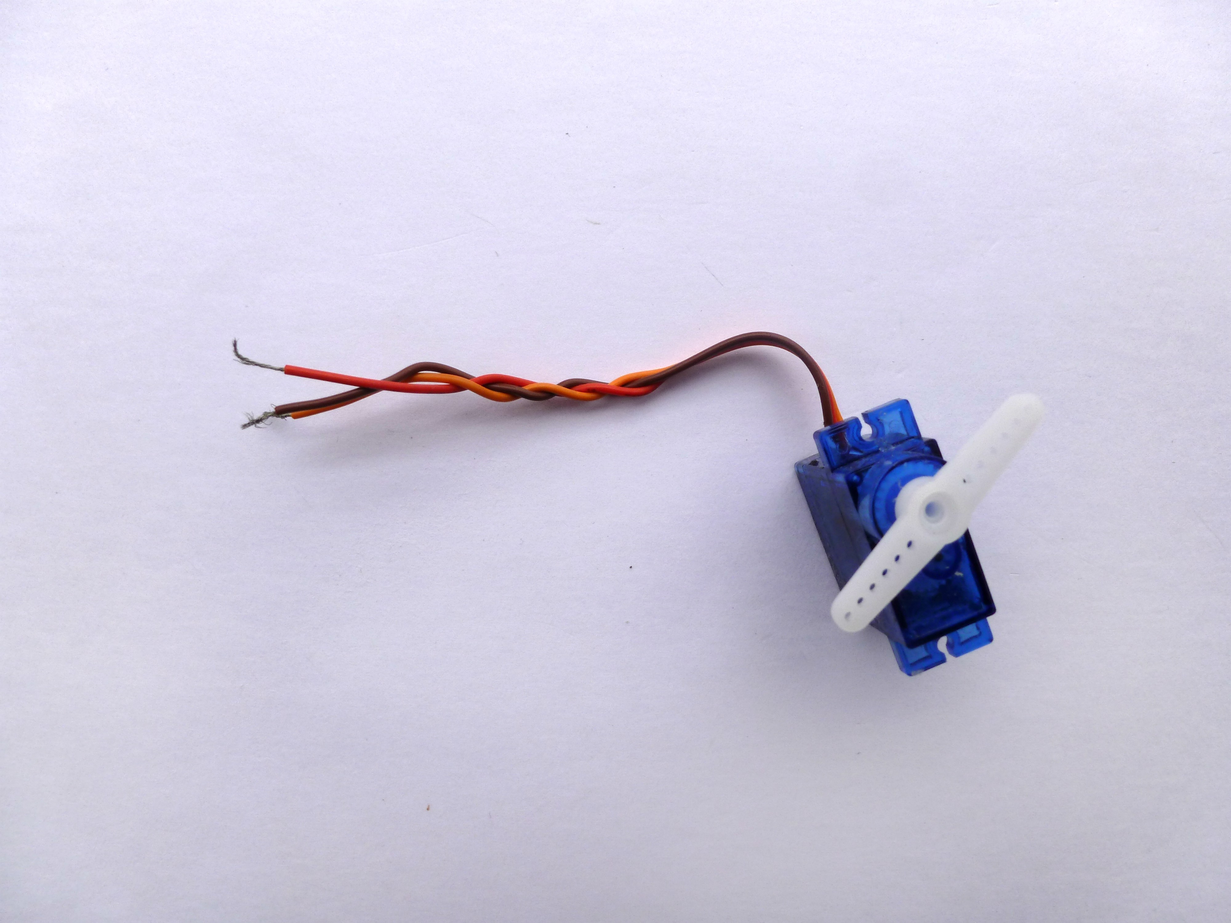
- Servo Motor
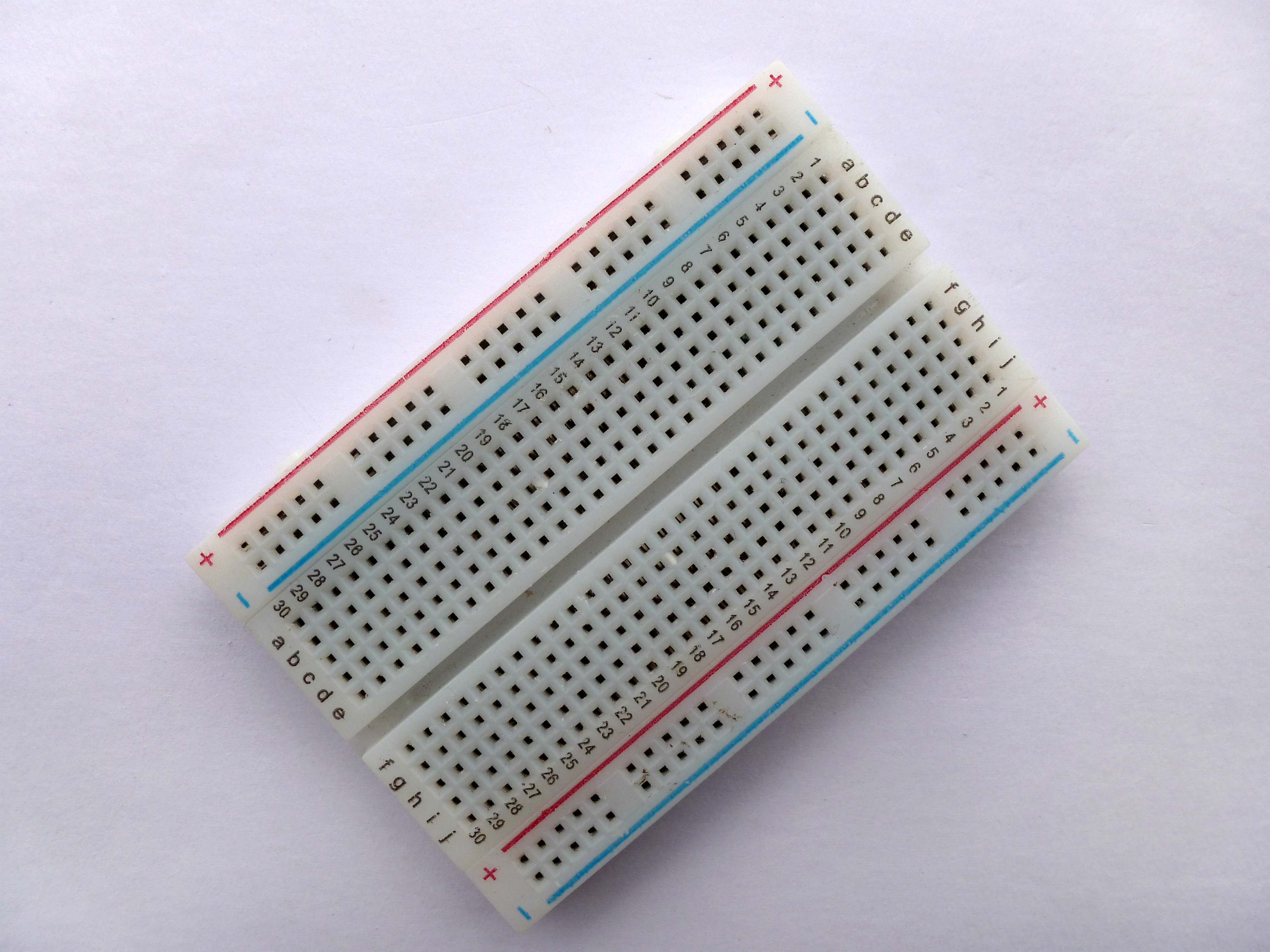
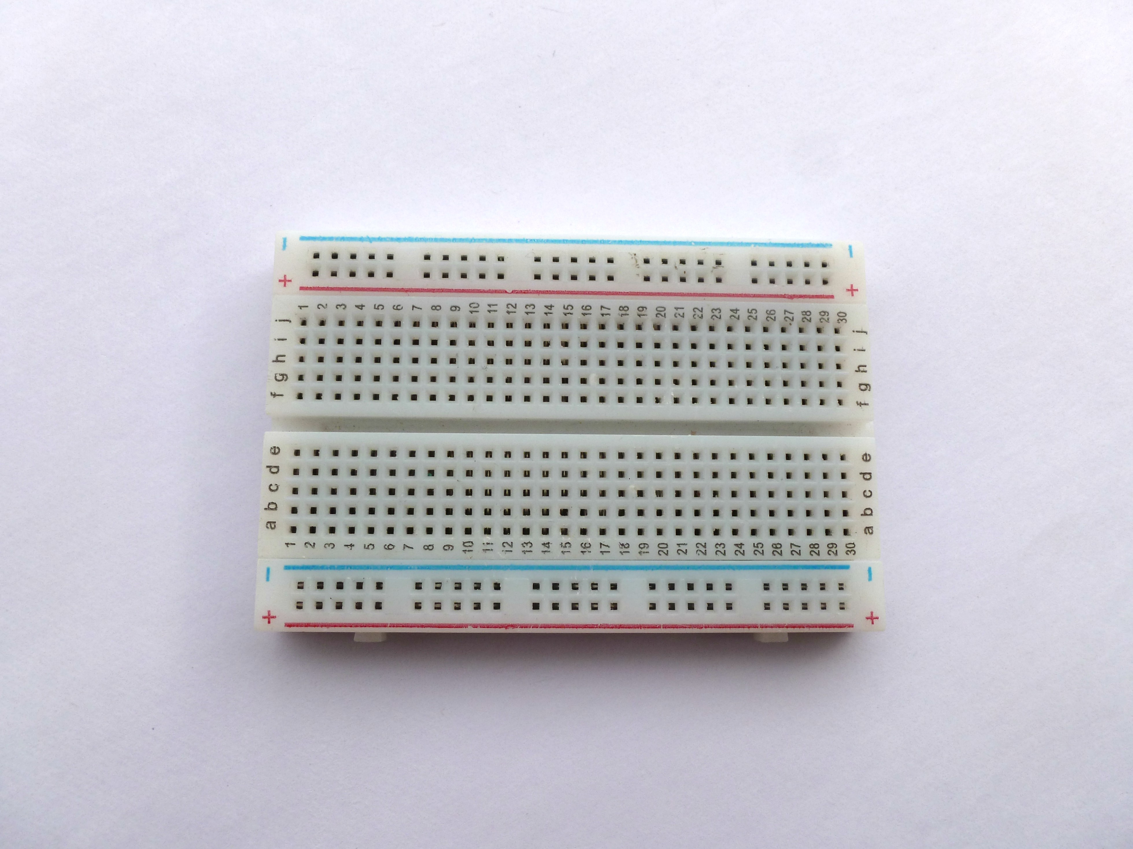
- Bread Board
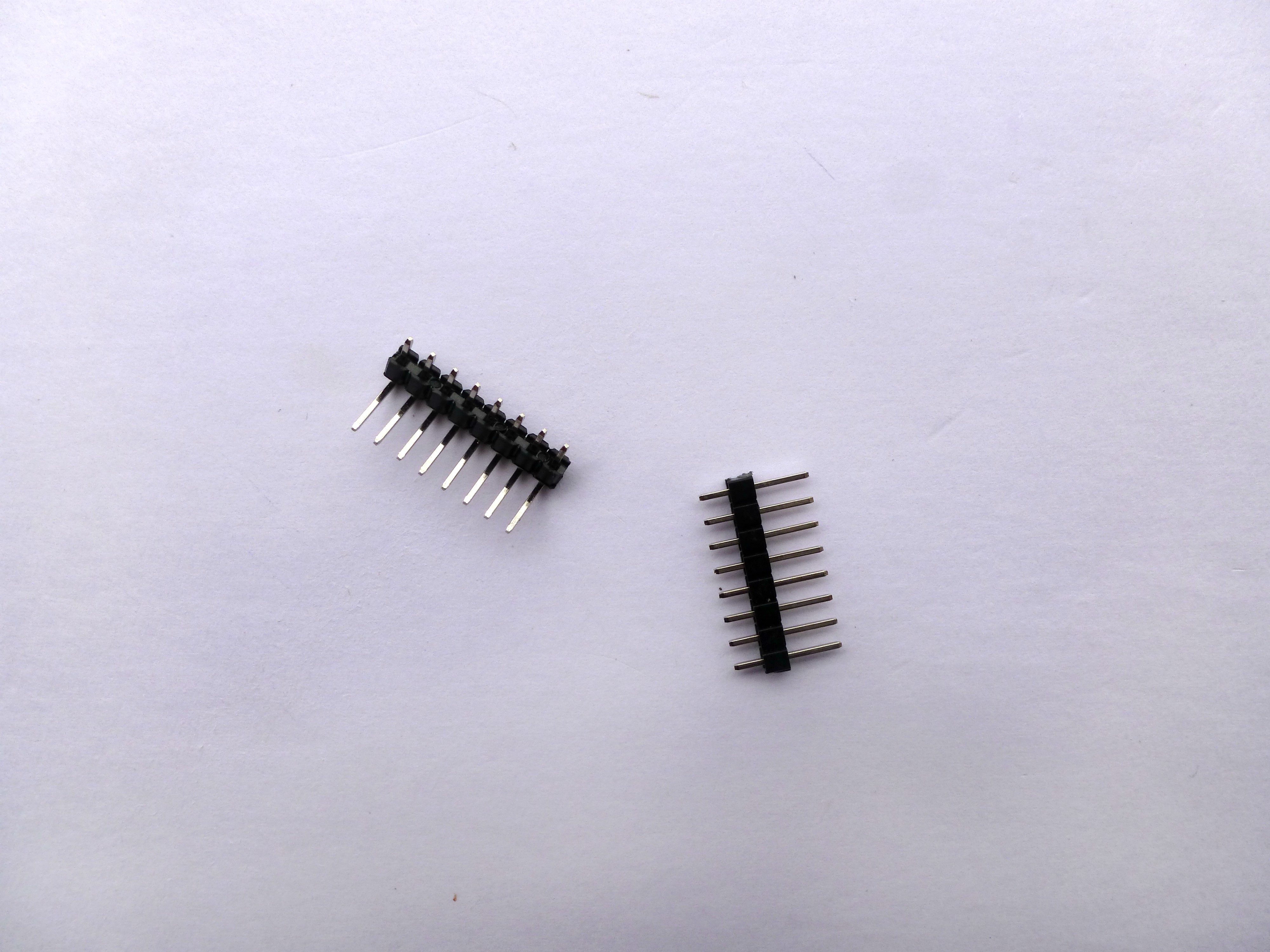
- Male Header pins
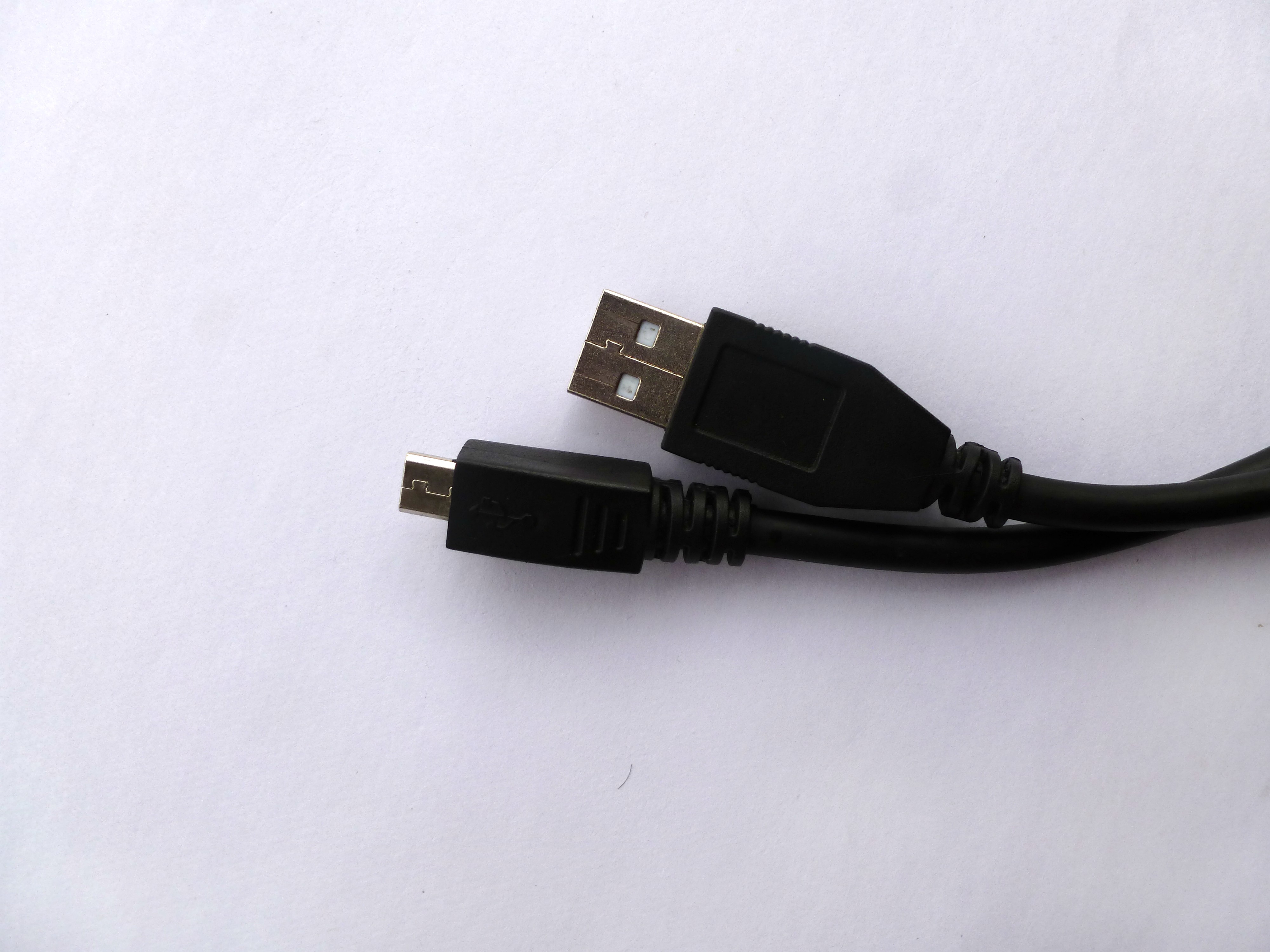
- Micro USB cable
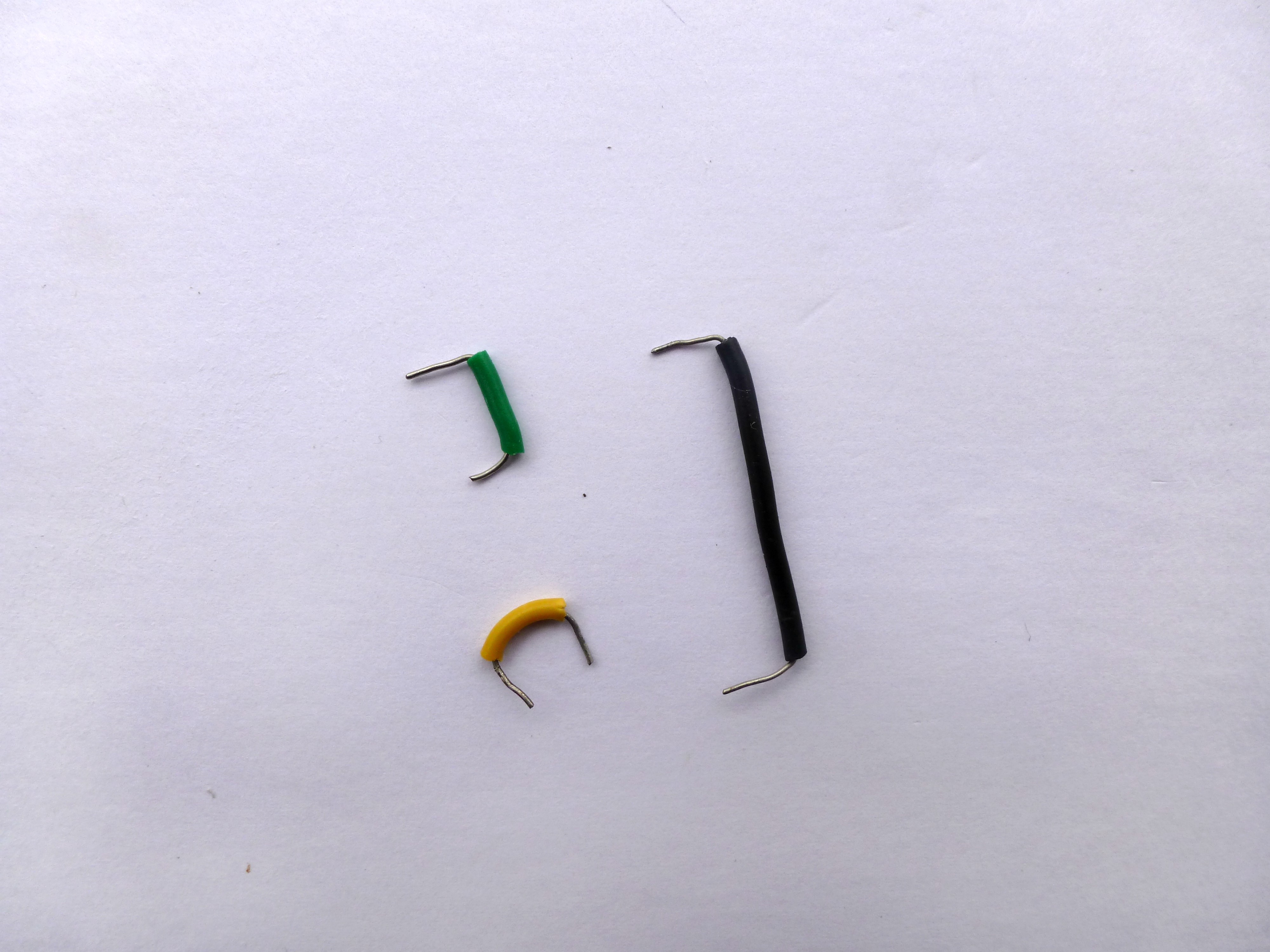
- Connecting Wires
Software Required
- Arduino IDE (with ESP8266 Library installed)
Description
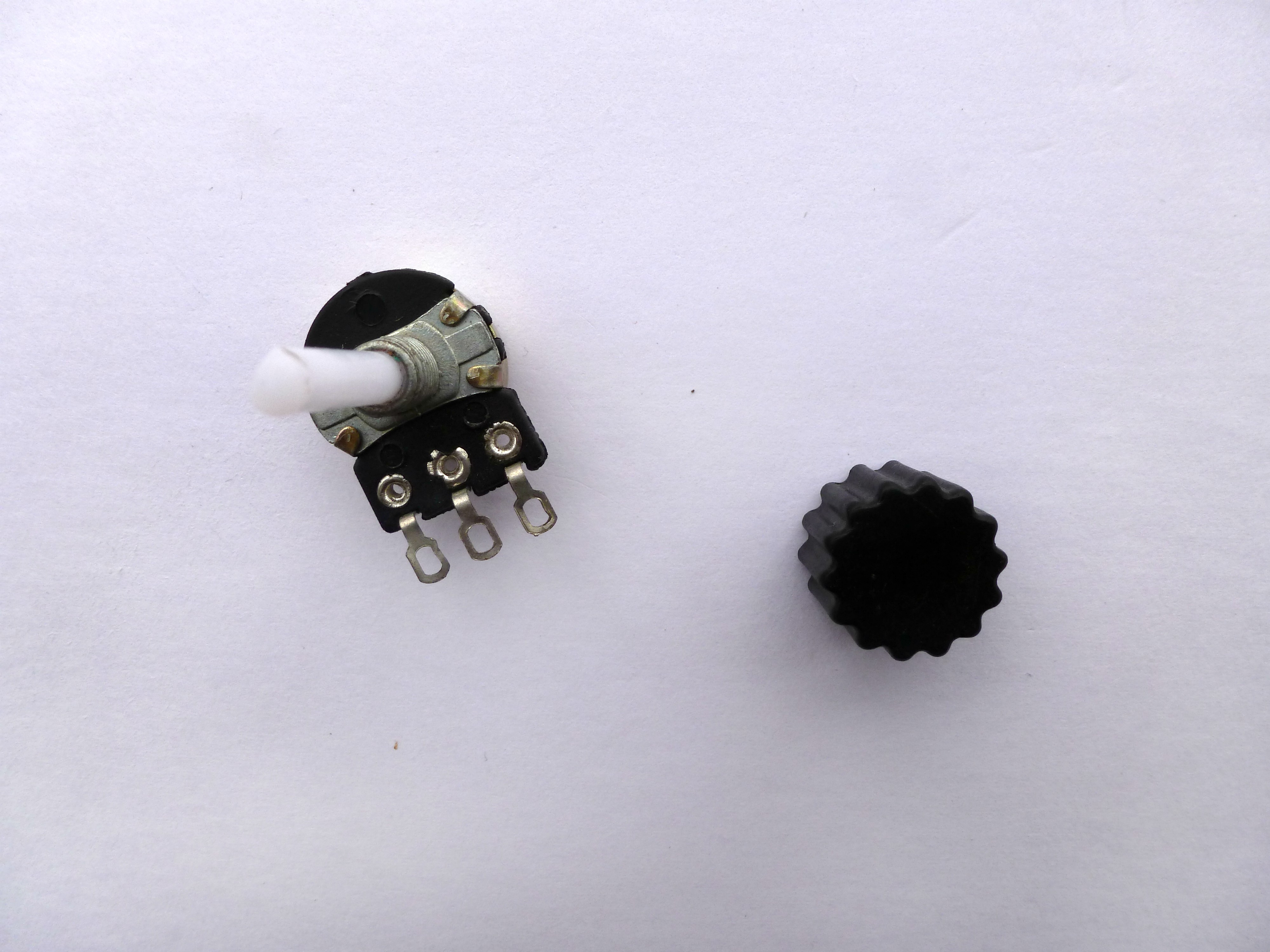
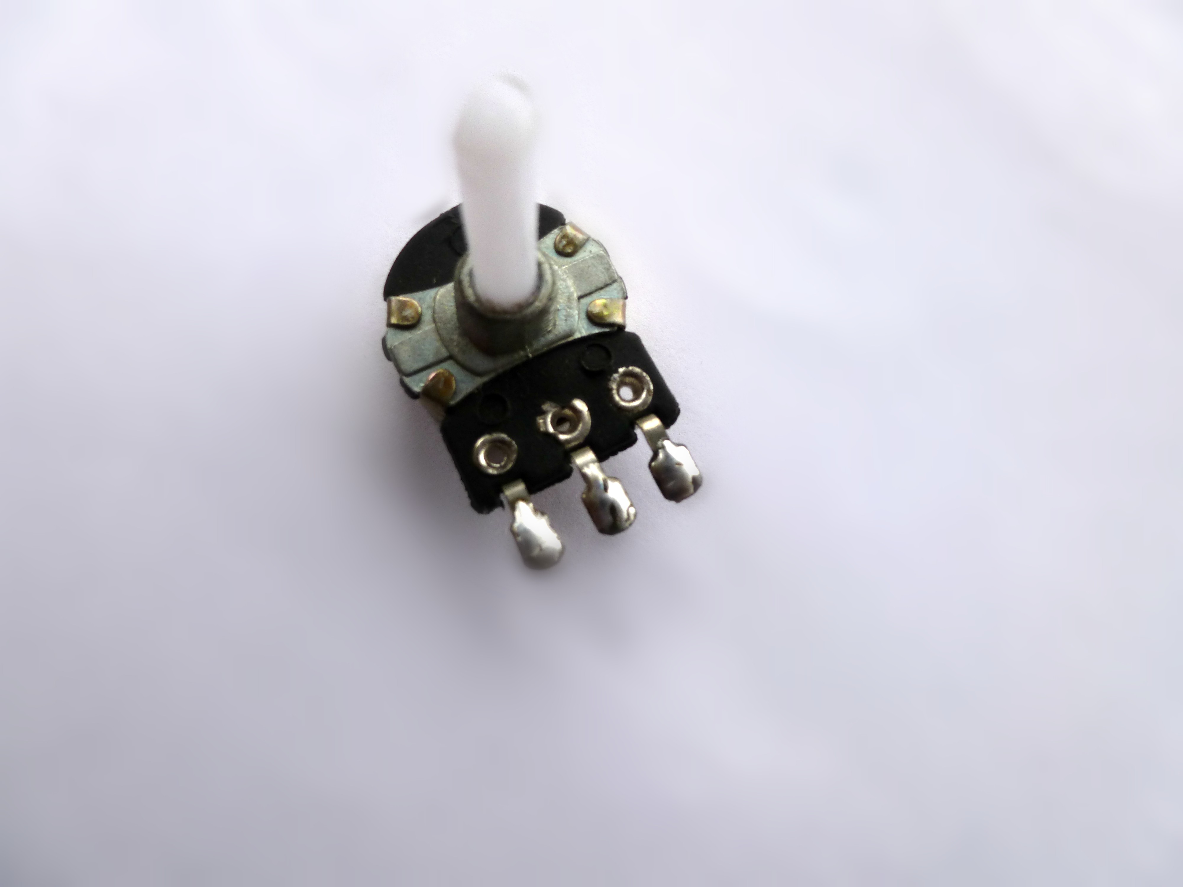
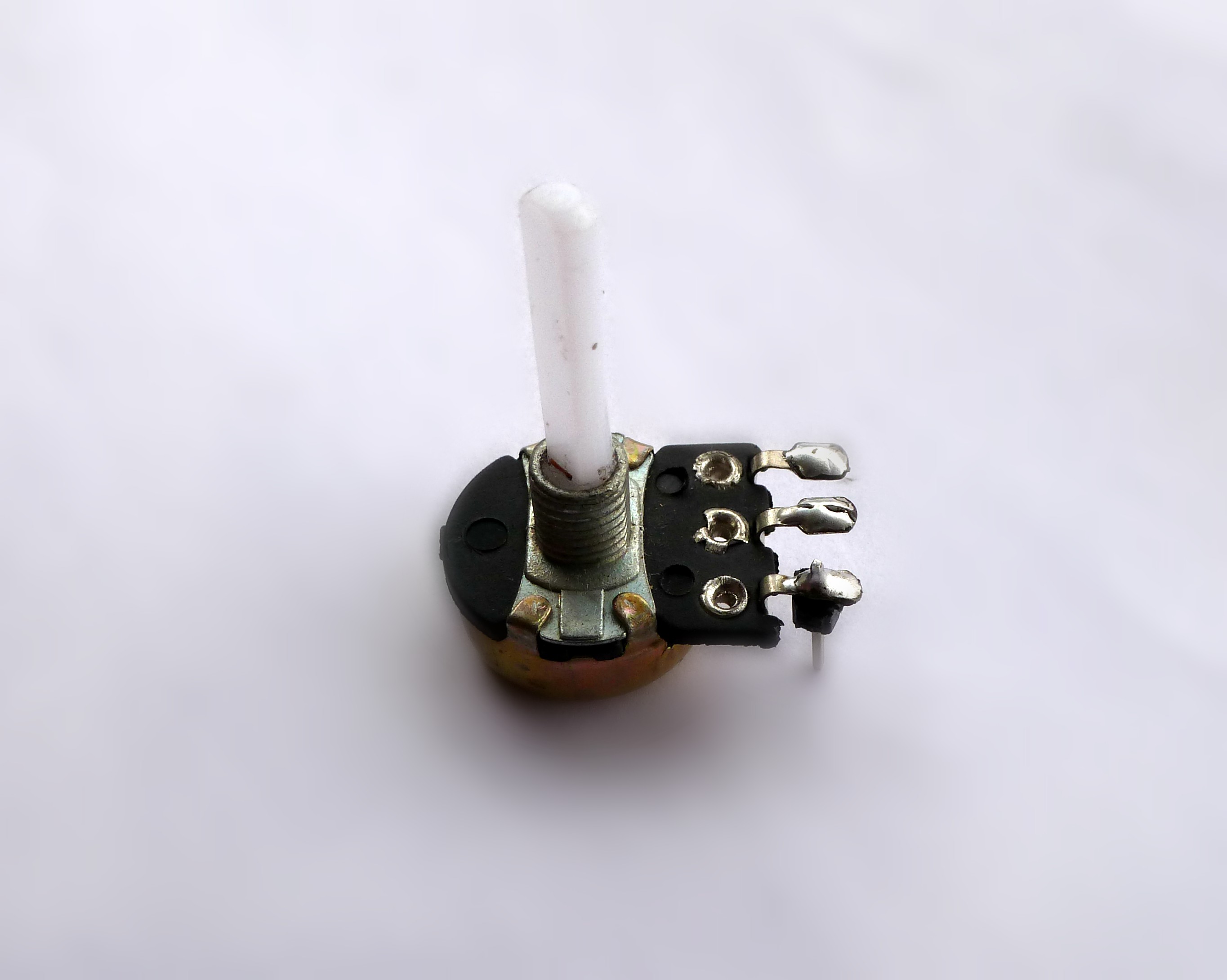
About Potentiometer
- A potentiometer is a three-terminal resistor with a sliding or rotating contact that forms an adjustable voltage divider.
- Potentiometers are commonly used to control electrical devices such as volume controls on audio equipment.
- Potentiometers operated by a mechanism can be used as position transducers, For example: In a joystick
Generally Potentiometer is called as variable resistors that change its resistance value (in ohms) when the rotating contact is turned/adjusted.
Therefore, using NodeMCU, we can control the servo arm to a specified position by turning the potentiometer.
As simple as that!
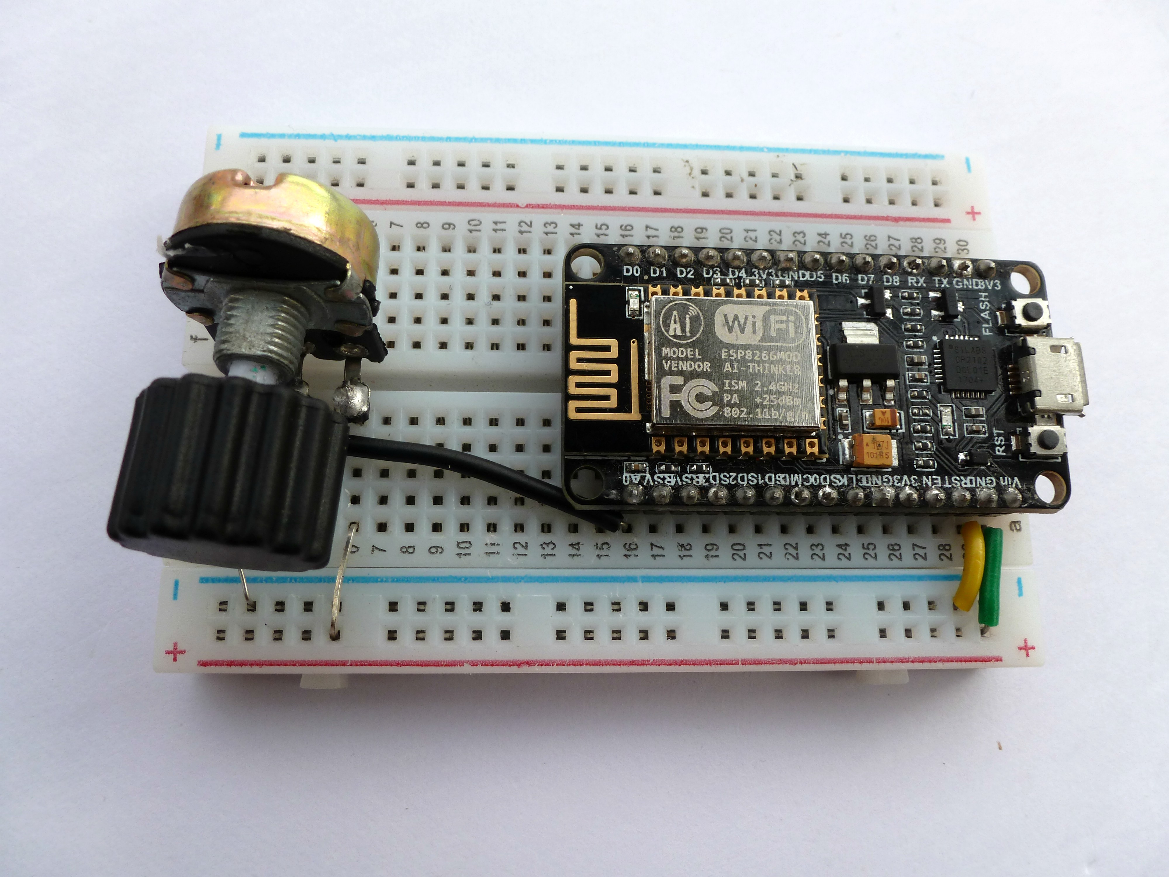
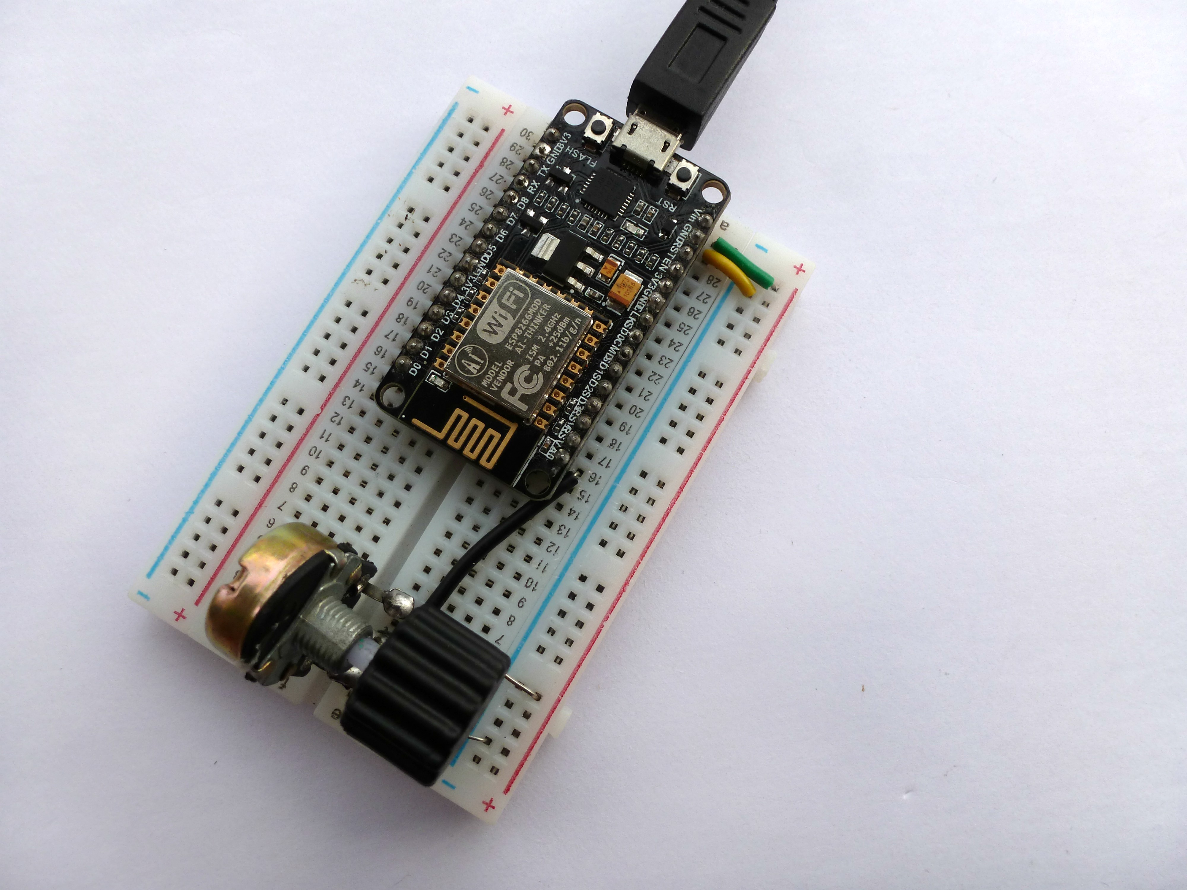
Soldering
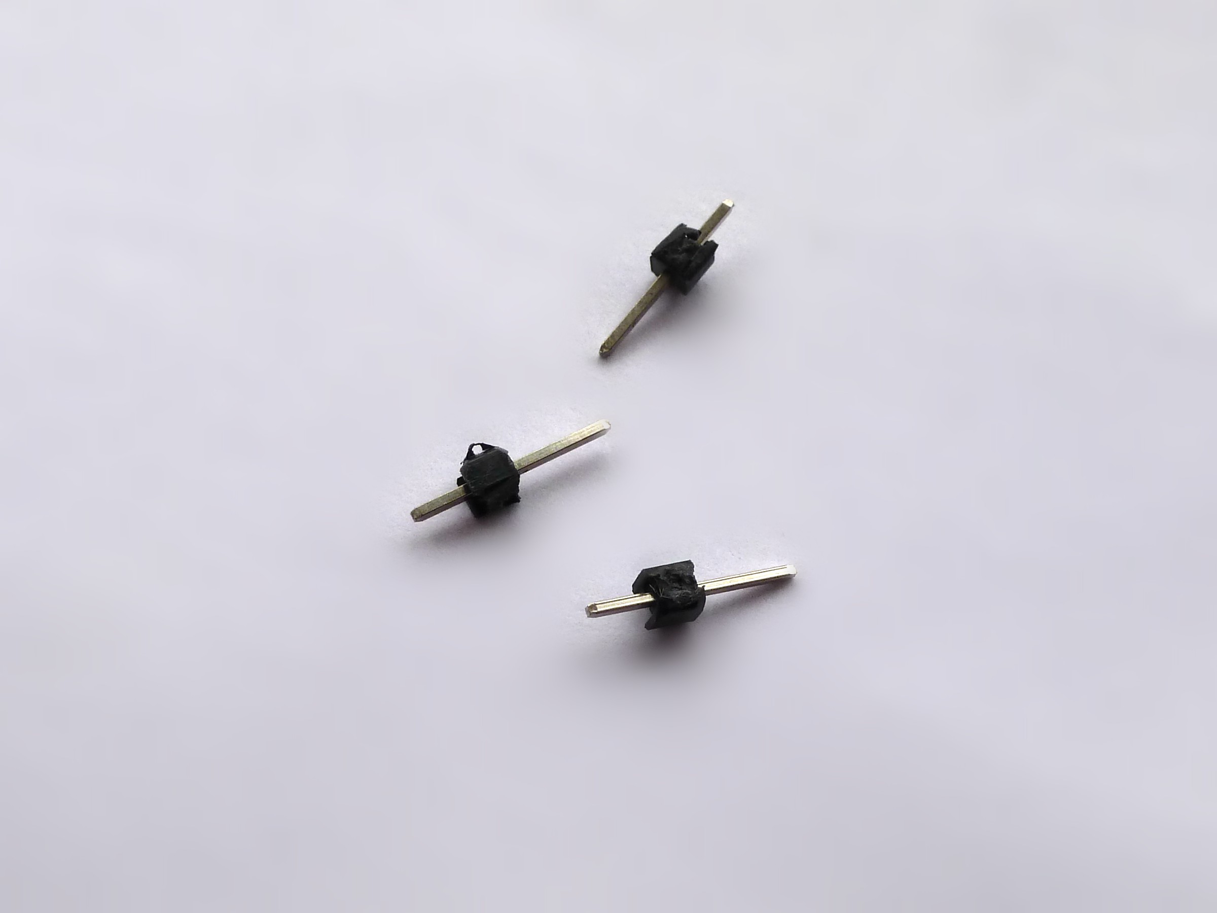
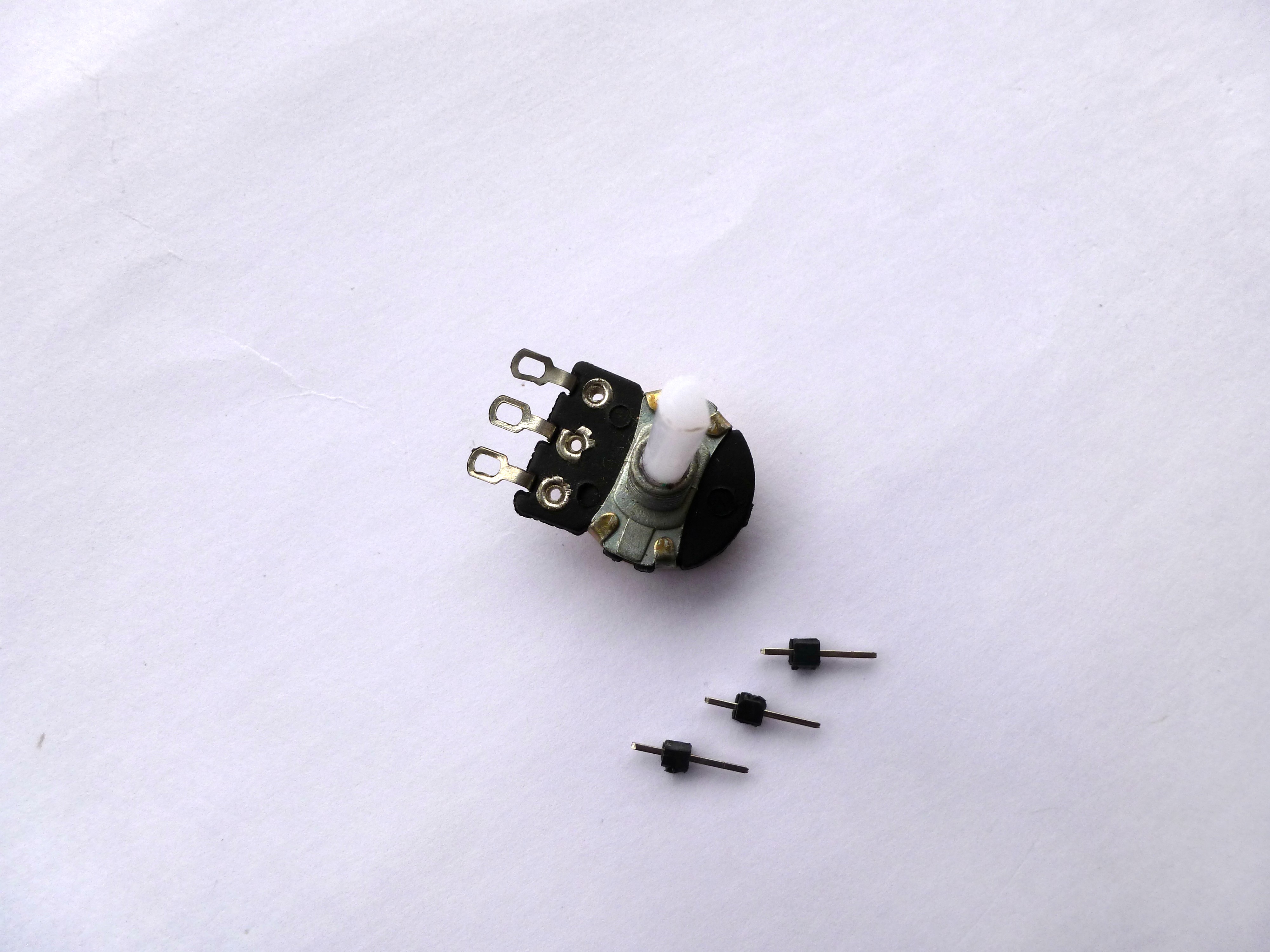
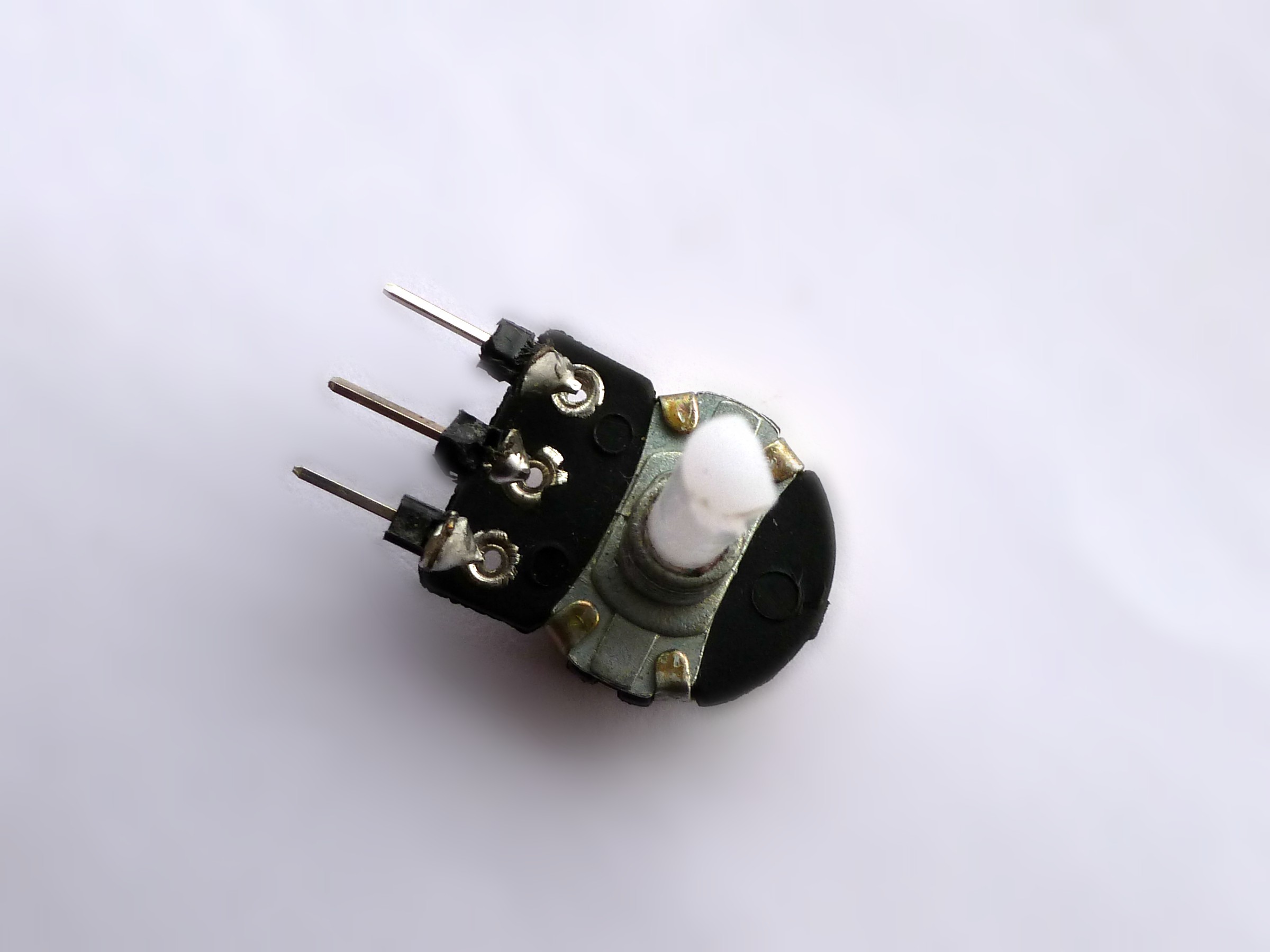
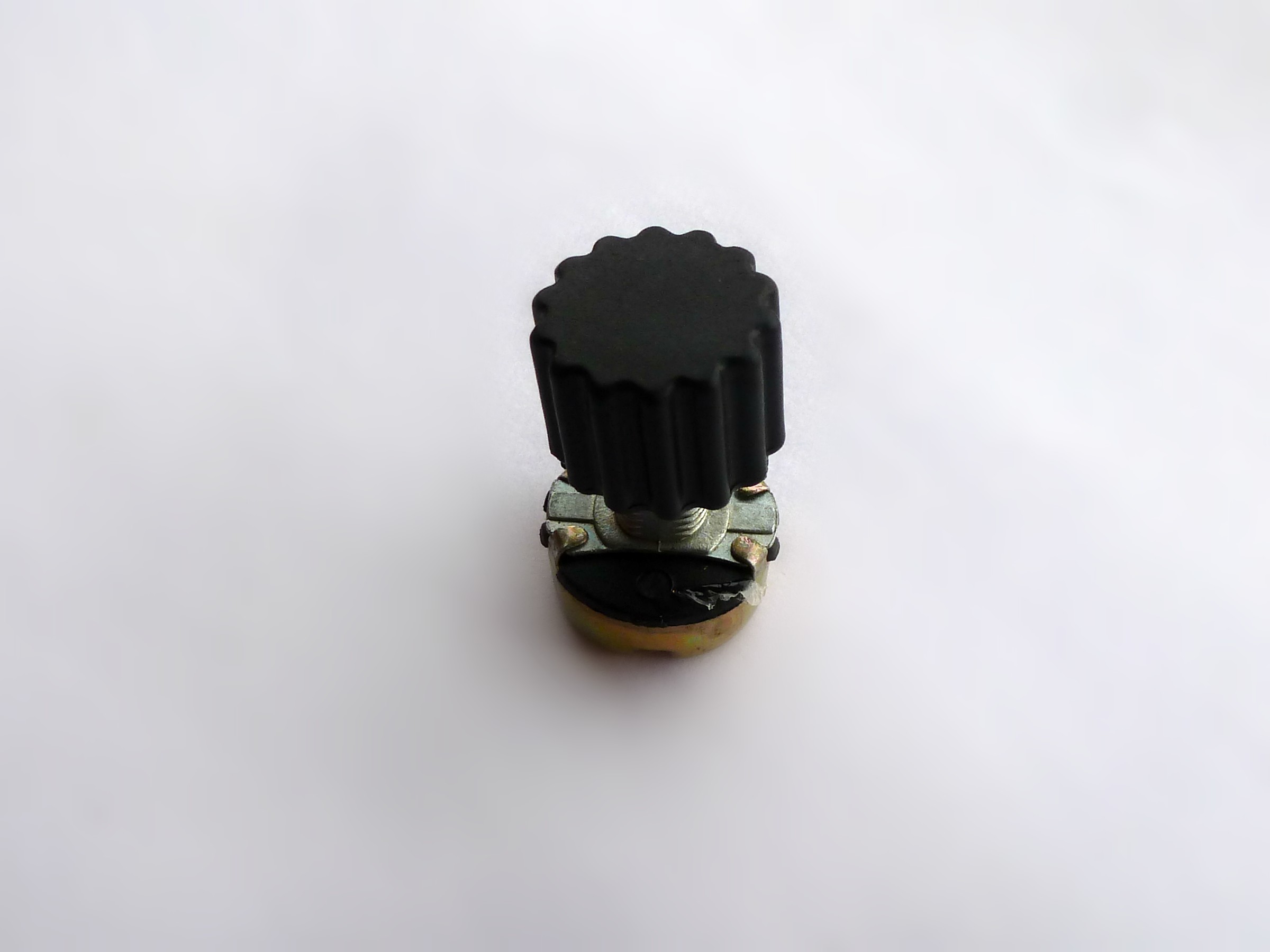
Solder Male Header pins to the Potentiometer, so it makes the connection to bread board easy.
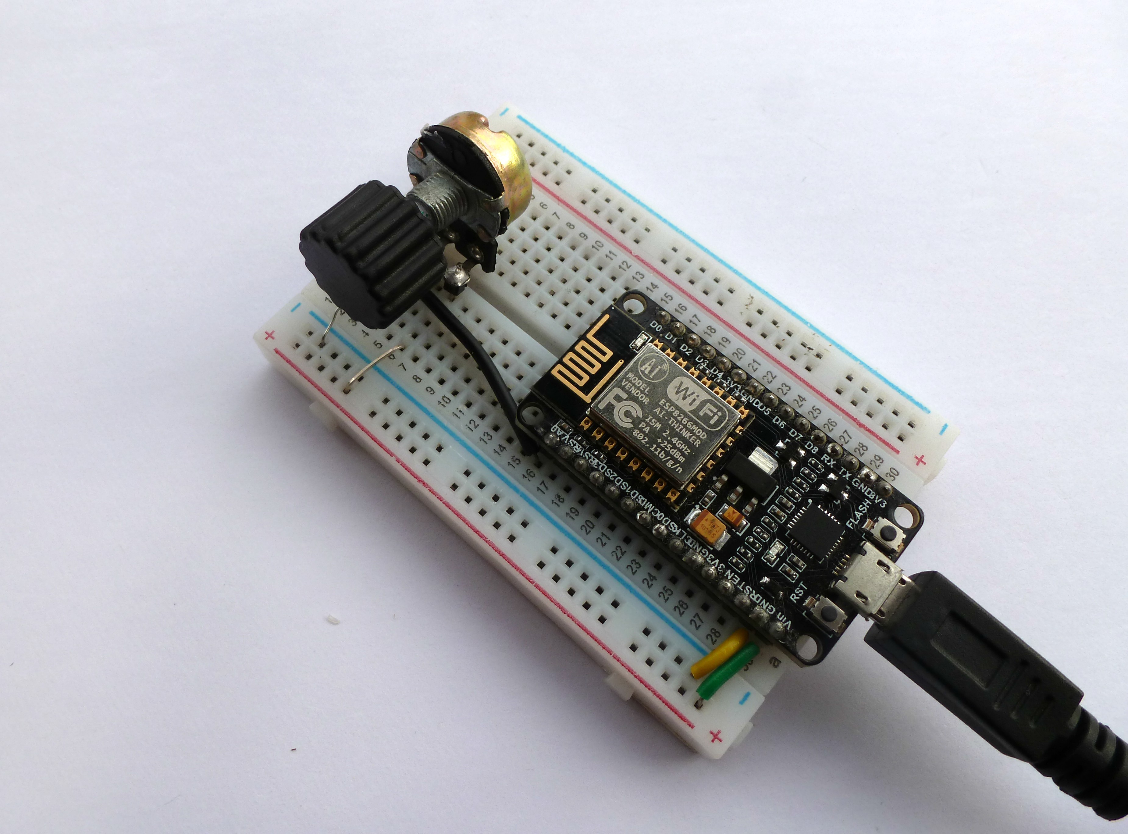
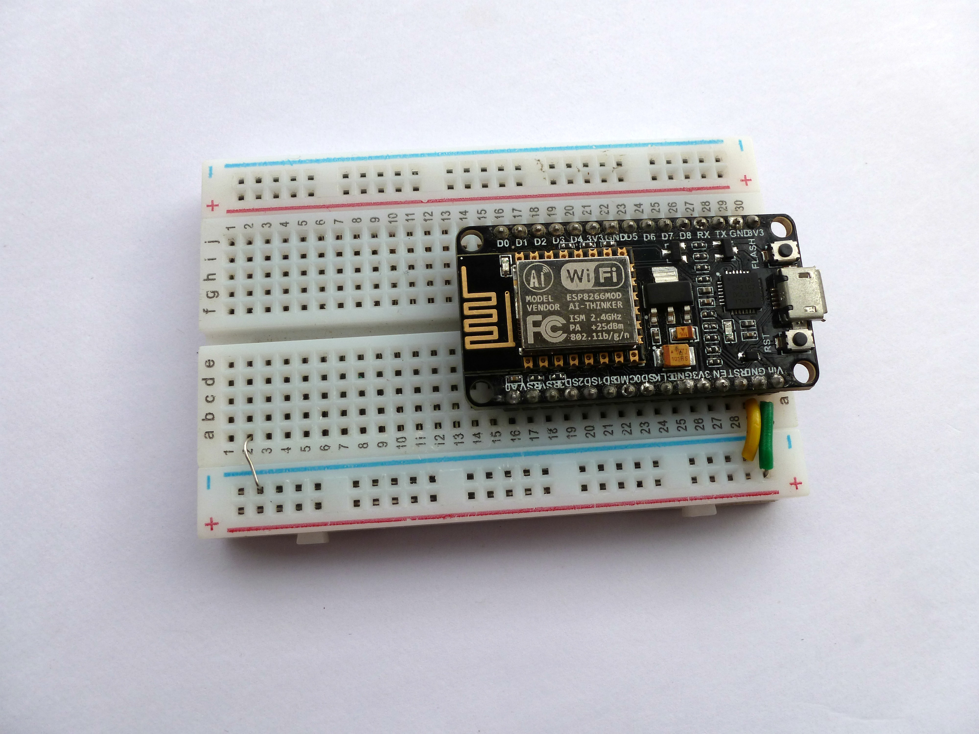
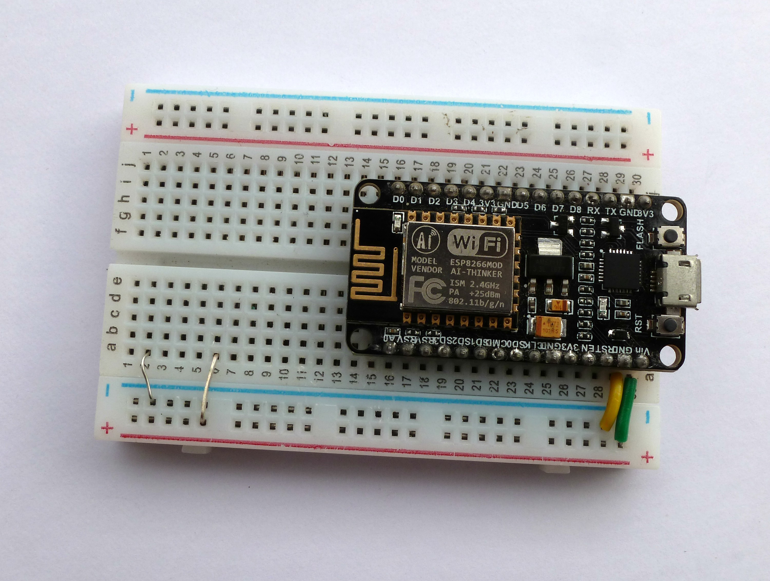
Circuit Wiring
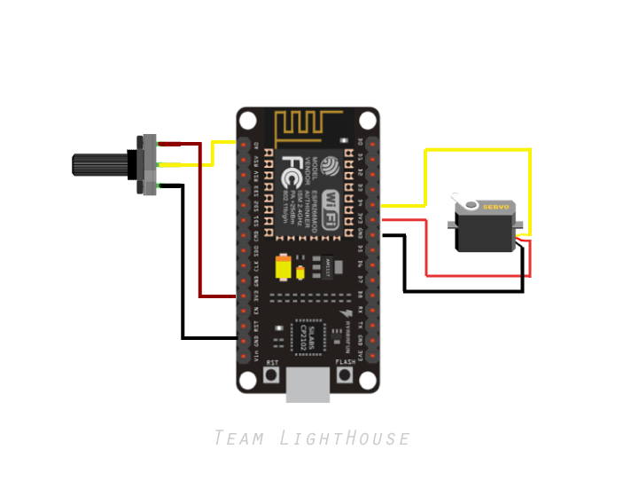
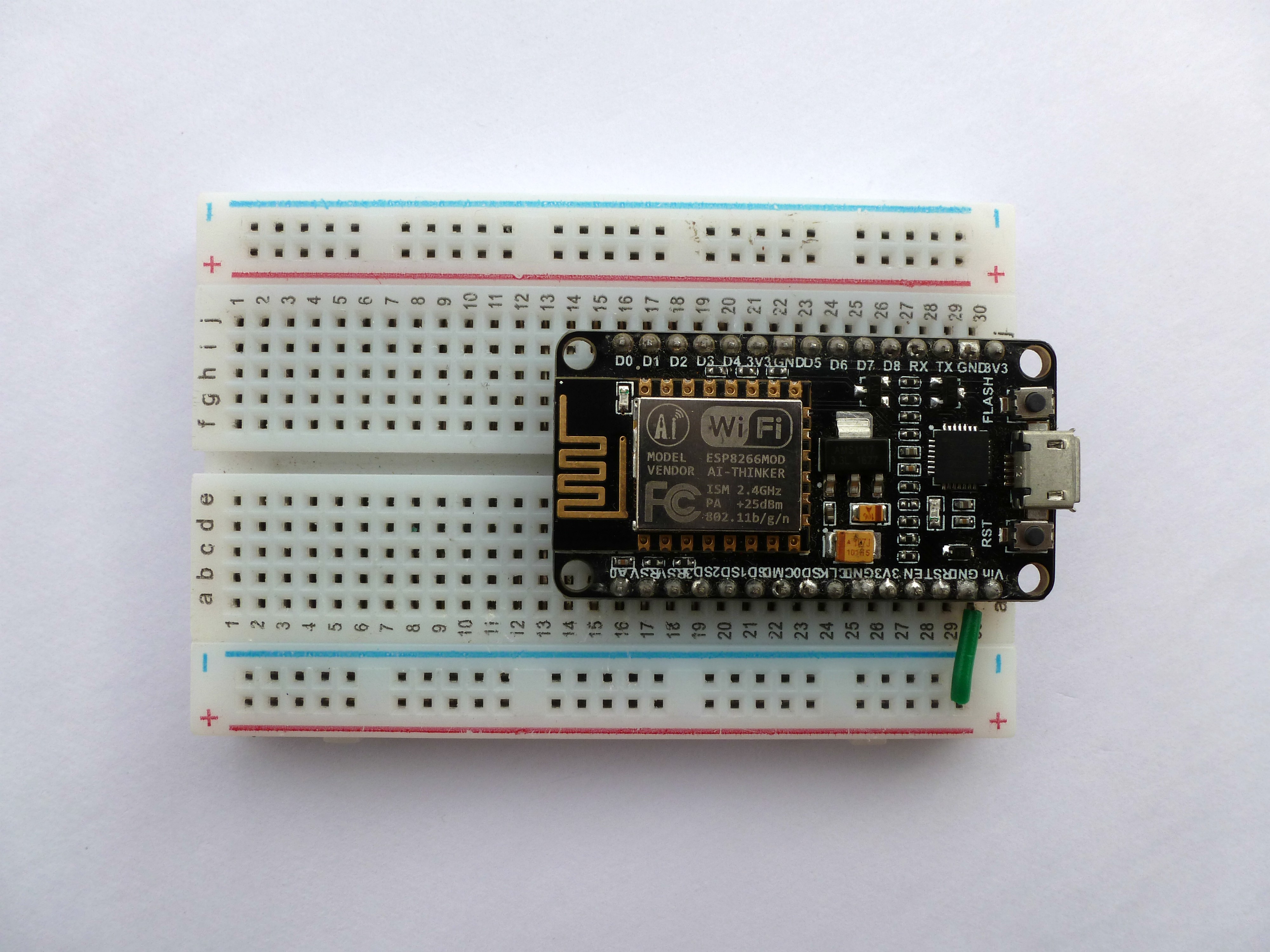
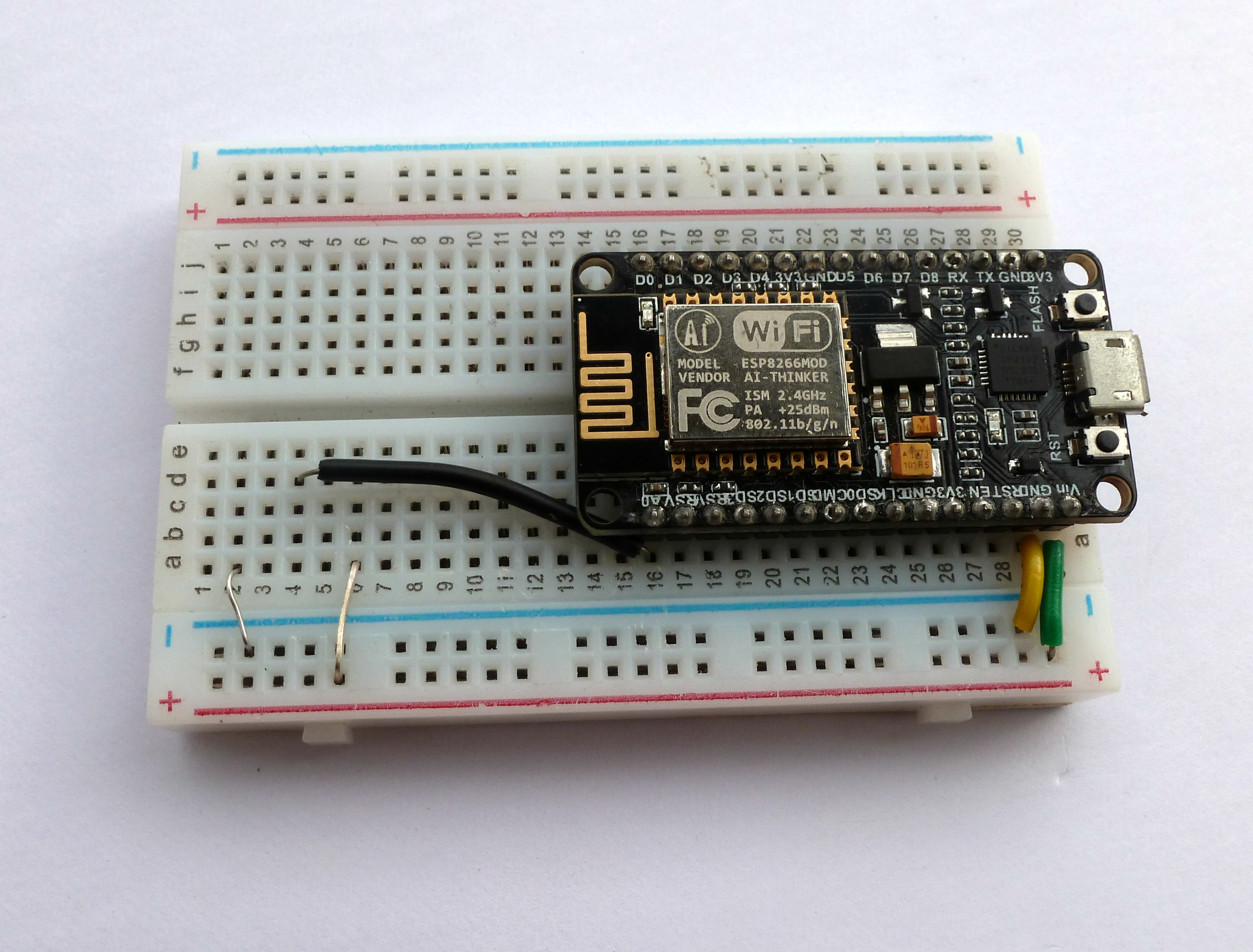
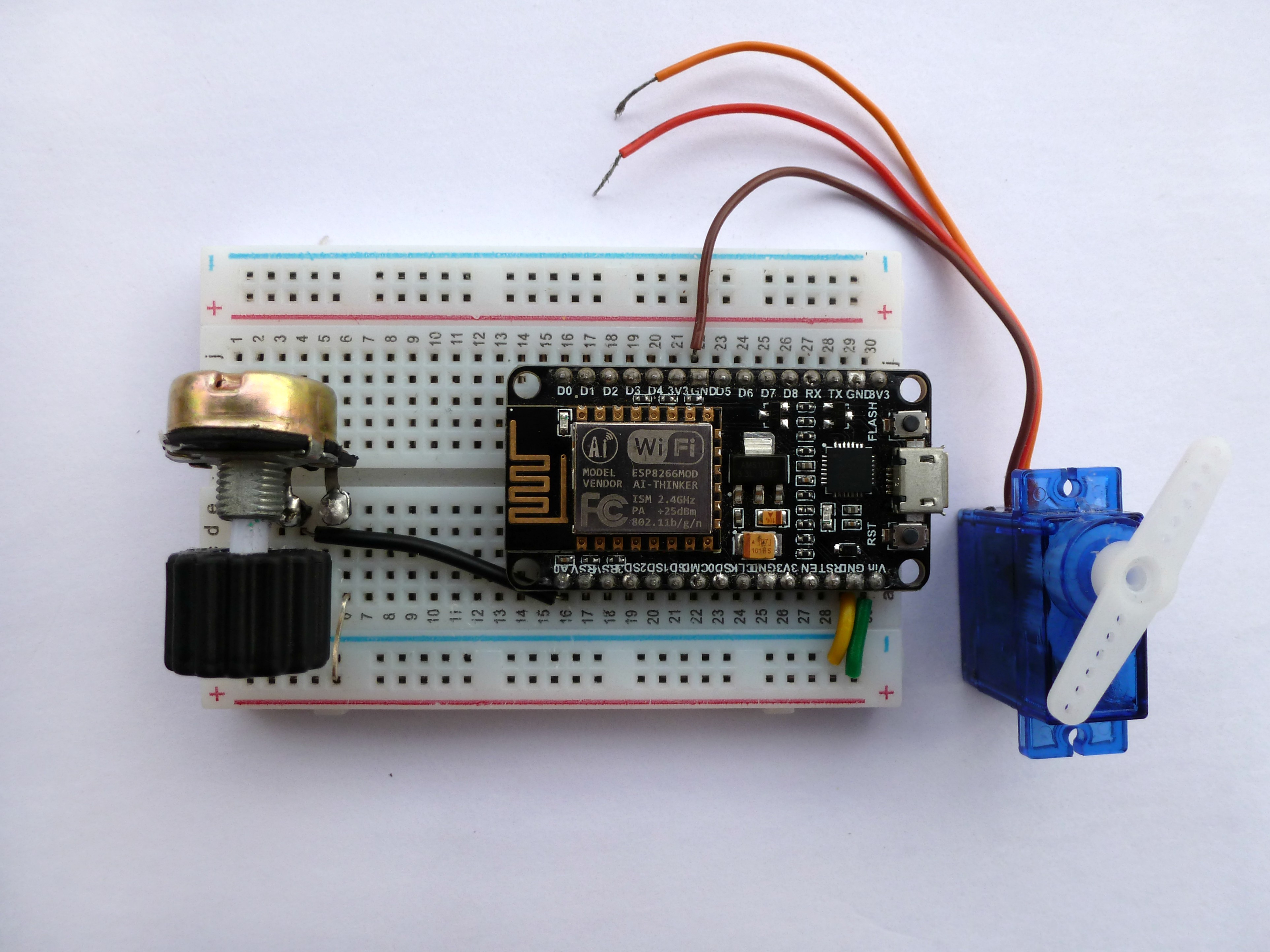
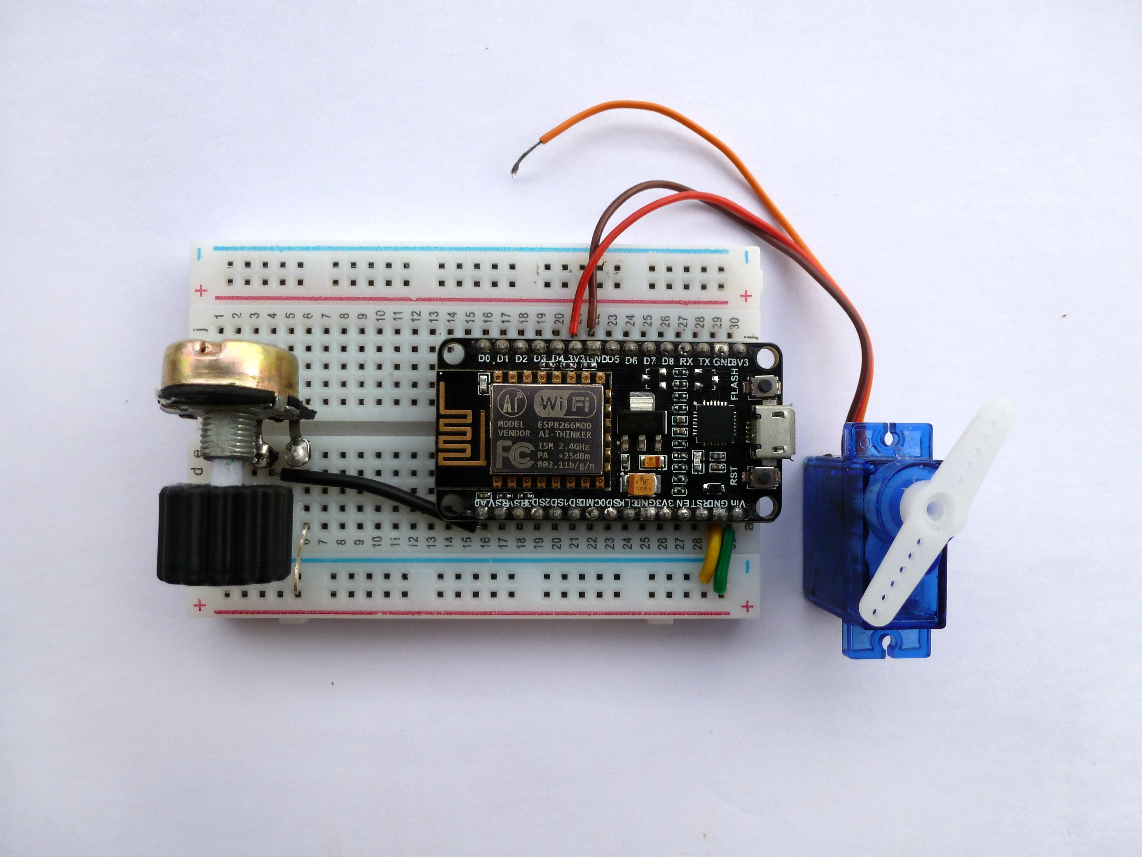
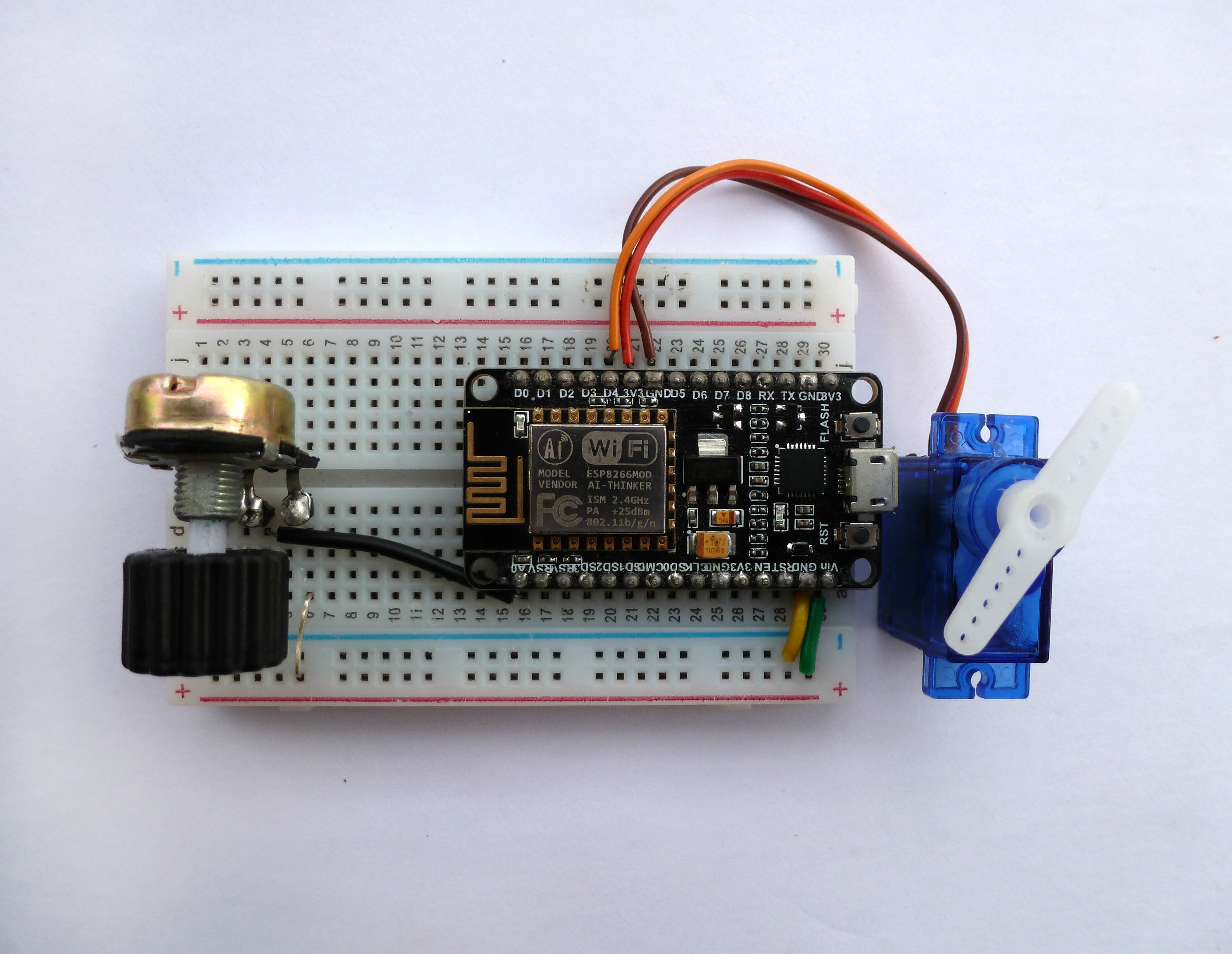
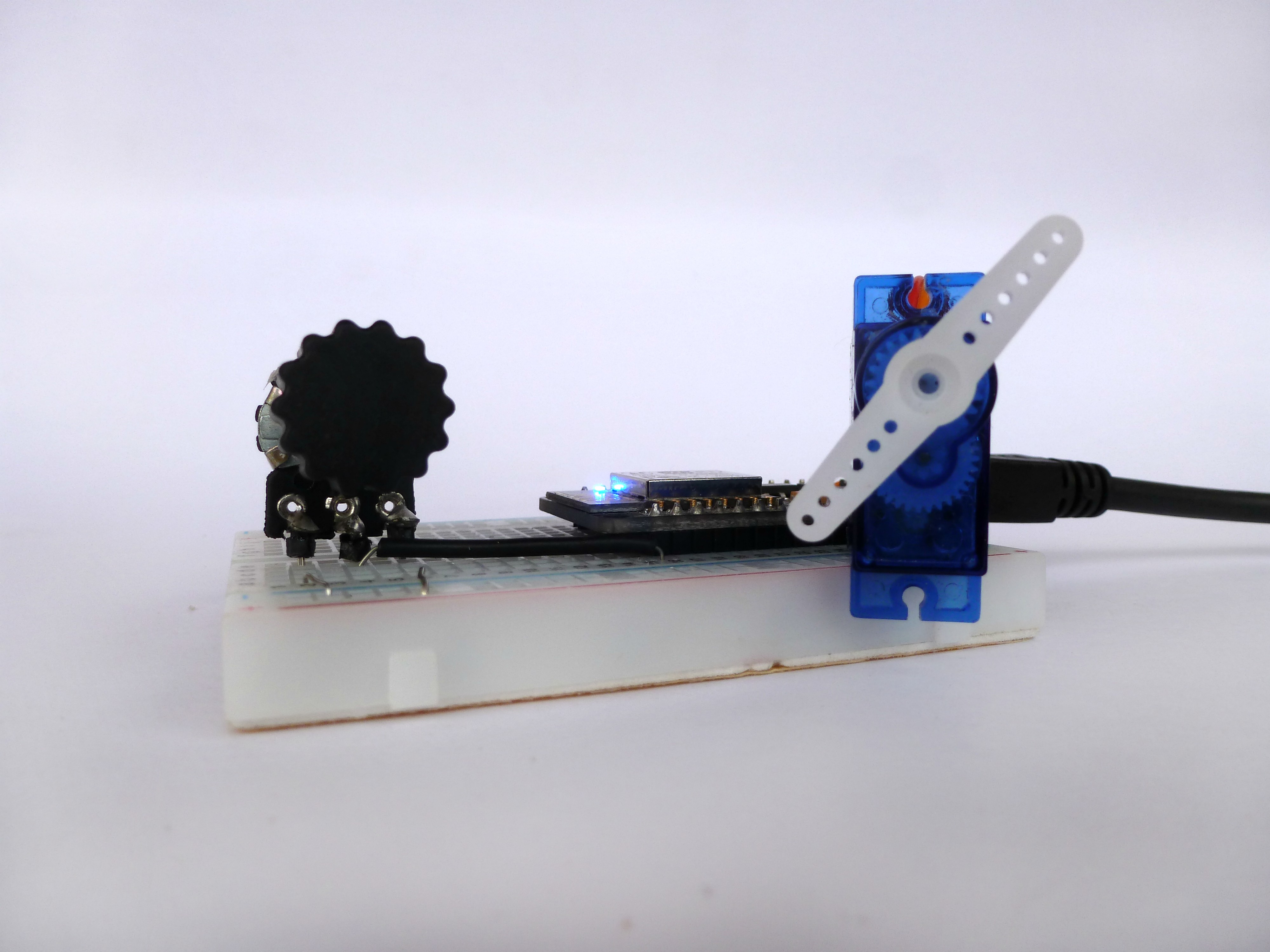
Servo connections:
The Orange wire connects to Digital pin D4.
The Brown wire connects to GND pin.
The red wire connects to 3v3 pin.
Pot connections:
The first pin is connected to the 3v3 pin.
The second pin is connected to Analog input A0 pin.
The third pin is connected to GND pin.
Coding Time
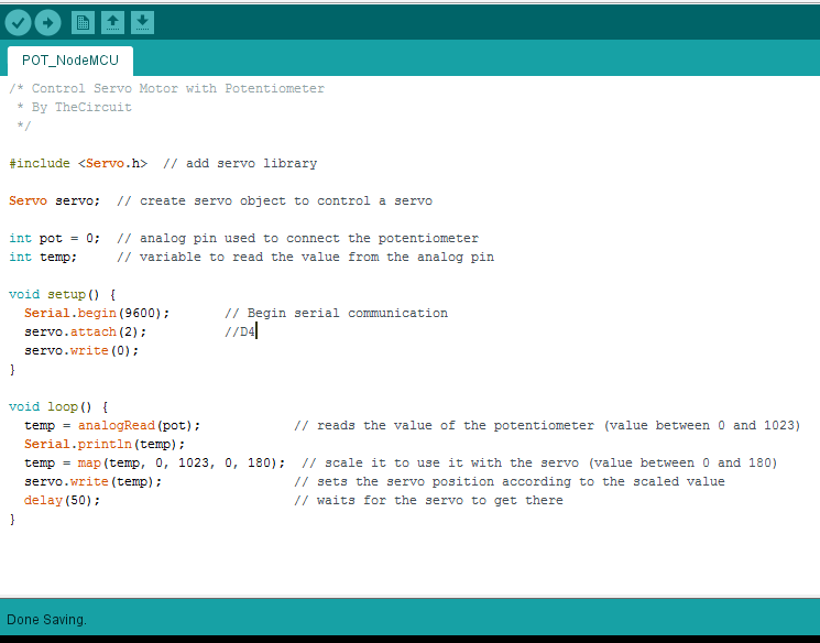
Make sure you include the Arduino Servo library.
CODE:
#include <Servo.h>
Servo servo; // create servo object to control a servo
int pot = 0; // analog pin used to connect the potentiometer<p>int temp; // temporary variable to read the value from the analog pin</p>
void setup() {<p> Serial.begin(9600);</p><p> servo.attach(4); // D2</p><p> servo.write(0);</p><p>}</p>void loop() {<p> temp = analogRead(pot); // reads the value of the potentiometer (value between 0 and 1023)</p><p> Serial.println(temp);</p><p> temp = map(temp, 0, 1023, 0, 180); // scale it to use it with the servo (value between 0 and 180)</p><p> servo.write(temp); // sets the servo position according to the scaled value
delay(50); // waits for the servo to get there
}</p>Download the "POT_NodeMCU.ino" file and open it up in the Arduino IDE.
Then Create a new sketch and paste the code below in the Arduino IDE and hit Upload.
You can tinker with it if you like based on the application, or just use it as it is.
Downloads
Output
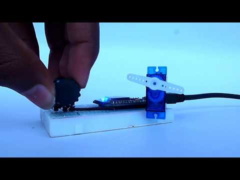
Using Serial monitor you can check the output from the analog pin connected to POT.
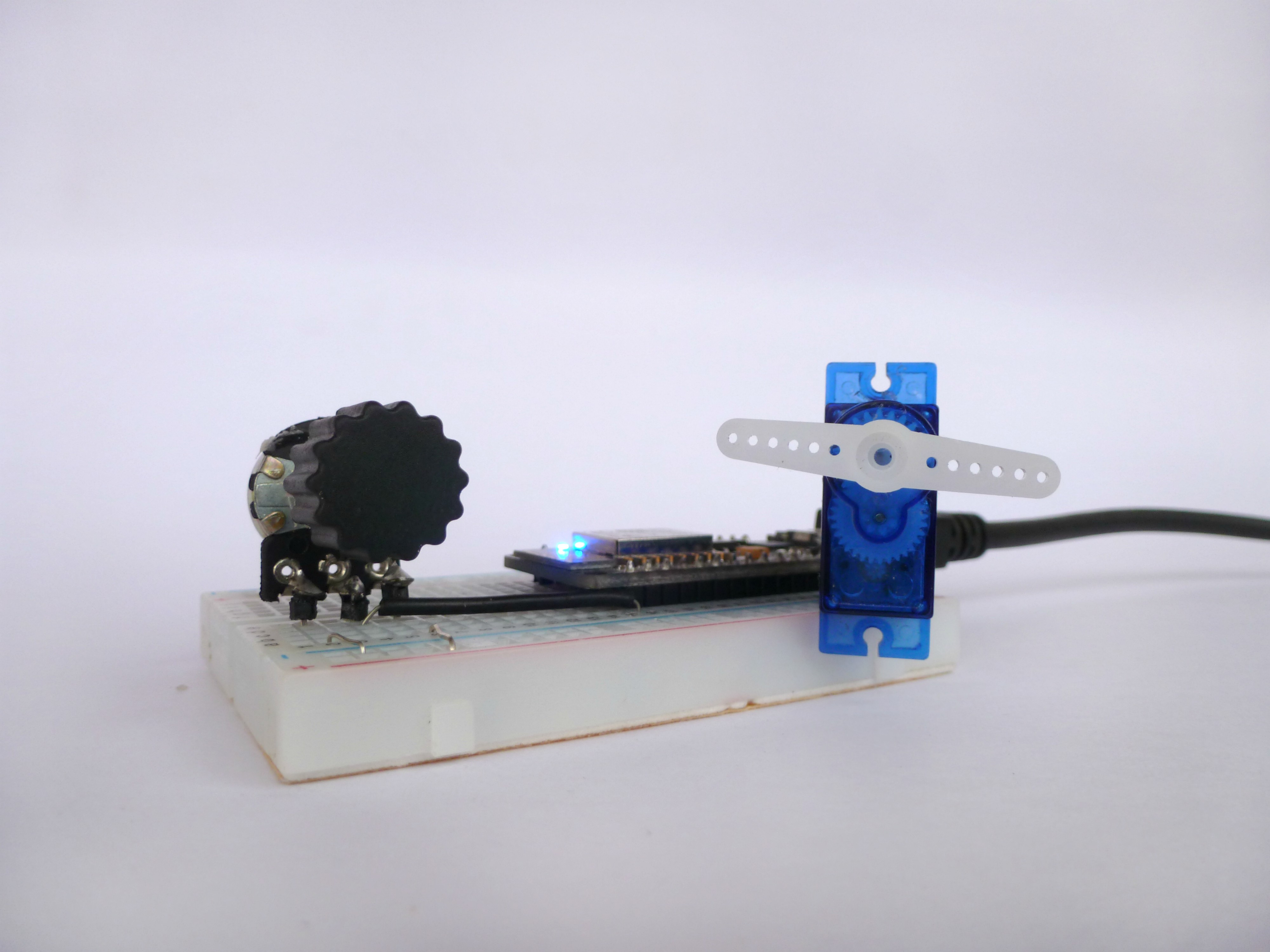
As you turn the rotating contact the servo arm is turned.
That's all makers!
I hope you liked this, Stay Tuned for more Projects!