Control House Lights With Google Assistant Using Arduino
by Mridul0001 in Circuits > Arduino
74625 Views, 45 Favorites, 0 Comments
Control House Lights With Google Assistant Using Arduino
(Update as on 22 Aug 2020: This instructable is 2 years old and relies on some third-party apps. Any change on their side might make this project non-working. It may or may not be working now but you can follow it as a reference and modify accordingly.)
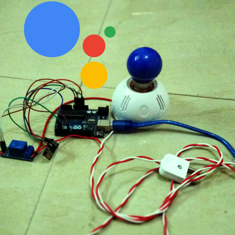
Hello! This is my first Instructable in which I am going to show how we can control lights of our houses with our voice through Google voice assistant using Arduino. Doesn't it sounds cool to switch on and off house lights just by giving command to Google voice assistant which probably we all have in our smartphones.
So lets get started with the Instructable. This Instrucable is not limited to lights only but you can control any appliance in your house. We will be using a "relay module" in this project because we are dealing with AC current.
Note: Ensure your safety first and proceed at your own risk as AC current in our houses operate at high voltage of 100V to 250V (varies for different countries).
Prerequisites
It will be beneficial if you fulfill following requirements before getting started:
1) IFTTT account (You can register for a free account on their website or app)
Note: Register with the same E-mail id which is associated with Google Assistant
2) Blynk account (You can register for a free account by downloading the blynk app)
3) Android device with Google Assistant (Running Marshmallow 6.0 or above, mine is 6.0)
Note: IOS device can be used having Google Assistant in it but I have personally not tested it.
4) Windows PC with 'Arduino IDE' installed
Kindly see the list of required components in next step.
Components Required (with Quick Specifications)
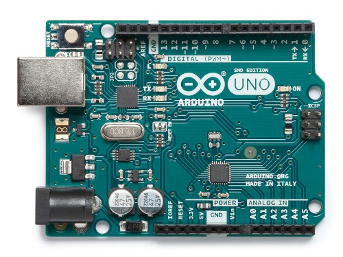
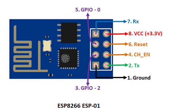
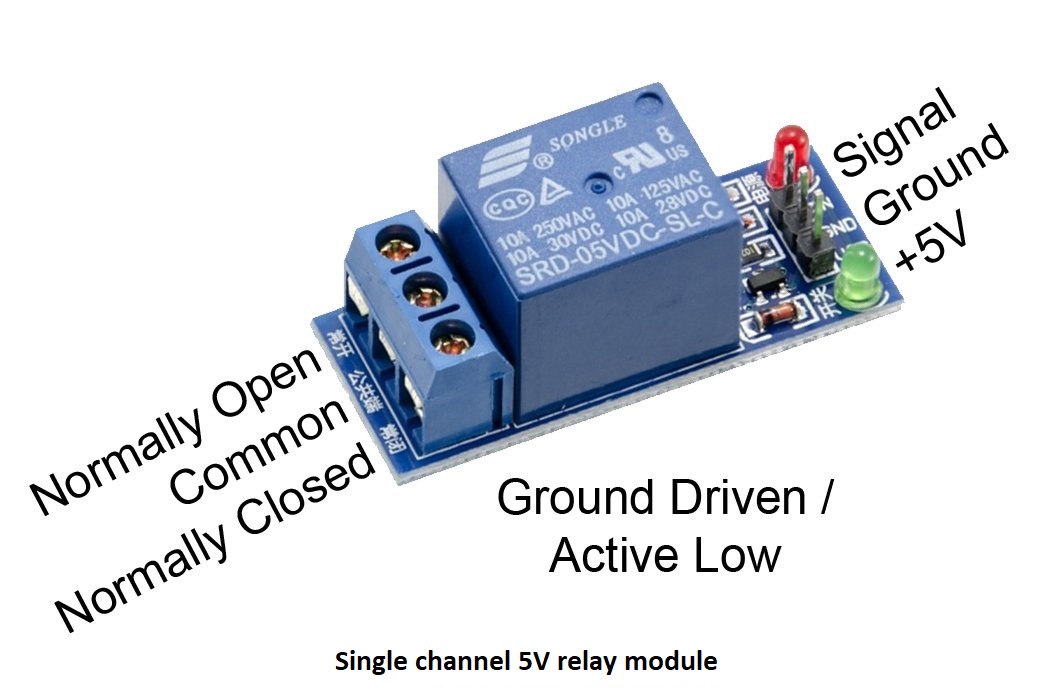
List of components required:
1) Arduino Uno R3 micro-controller board (Quantity: 1)
2) ESP8266 ESP-01 WiFi module (Quantity: 1)
3) Relay module(Single Channel 5V) (Quantity: 1)
4) Jumper Wires (Quantity:As per requirement)
5) AC Bulb, Light bulb socket and electric wires(Quantity: 1 Bulb, 1 light bulb socket,
Electric wire of length as required.)
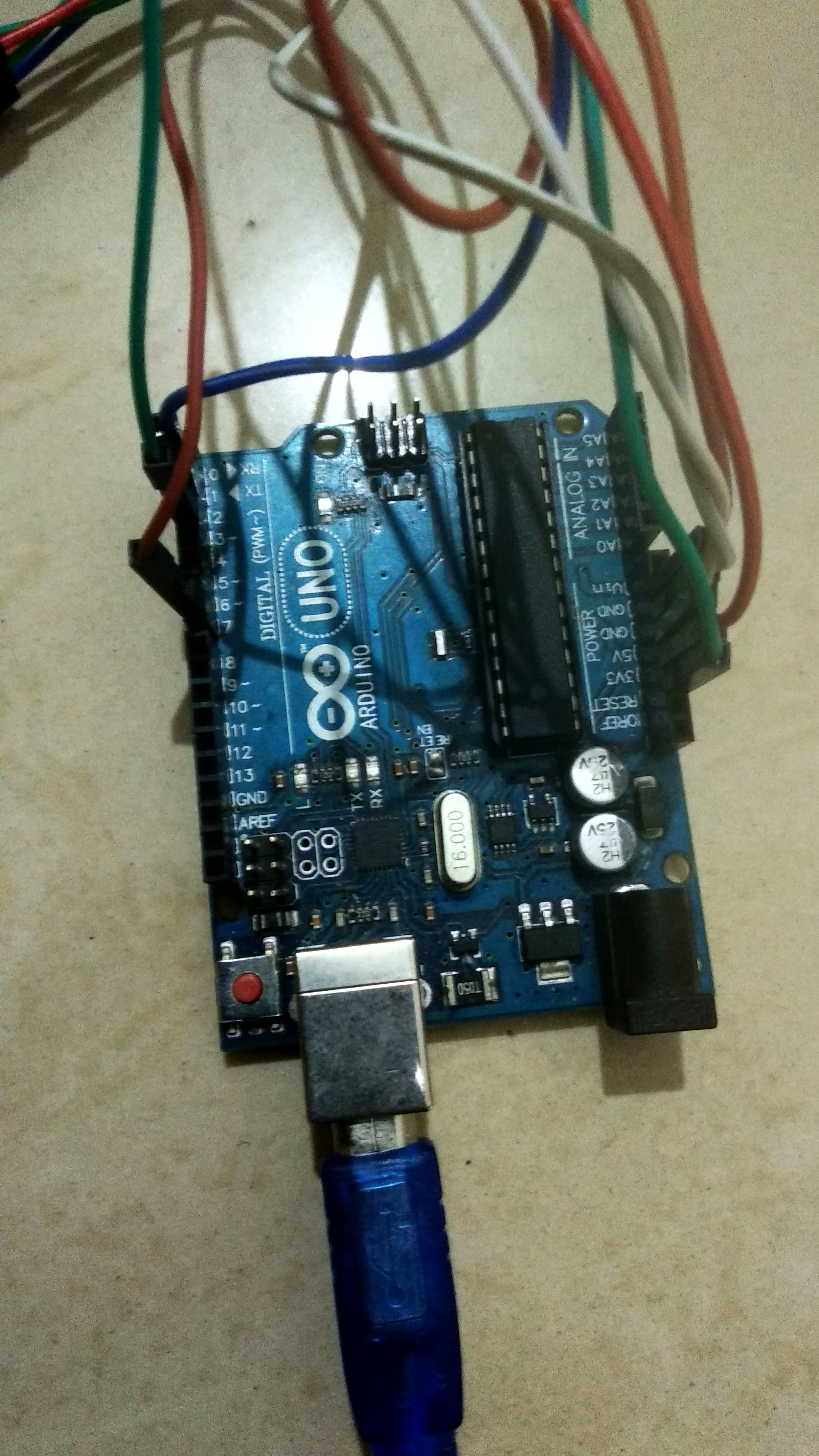
1) Arduino Uno R3 micro-controller board: Most probably you might be familiar with Arduino micro-controllers. For those who are not, you can assume it as of a core component in most of your IoT(Internet of Things) projects. In this project I have used " Arduino Uno". ATmega328 based MCU. It has 14 digital I/O pins (of which 6 pins can be used for PWM output), 6 analog input pins, operates on 5V and input voltage ranges from 7V-20V, 20 MHz clock speed with 32 kb flash memory.
We can connect various sensors to it and put our logic in a code to get the required functionality from sensors and upload the final sketch to Arduino through 'Arduino IDE'.
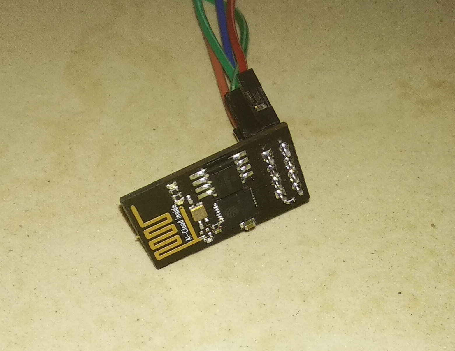
2) ESP8266 ESP-01 WiFi module: ESP8266 ESP-01 is the most affordable WiFi module and we use it to connect our micro-controller to a WiFi network and make small TCP/IP connections. It has 8 pins on chip which are Ground, TX, GPIO-2(General purpose I/O), CH_EN(Chip Enable), GPIO-0, Reset, RX, Vcc. It operates on +3.3v power supply.
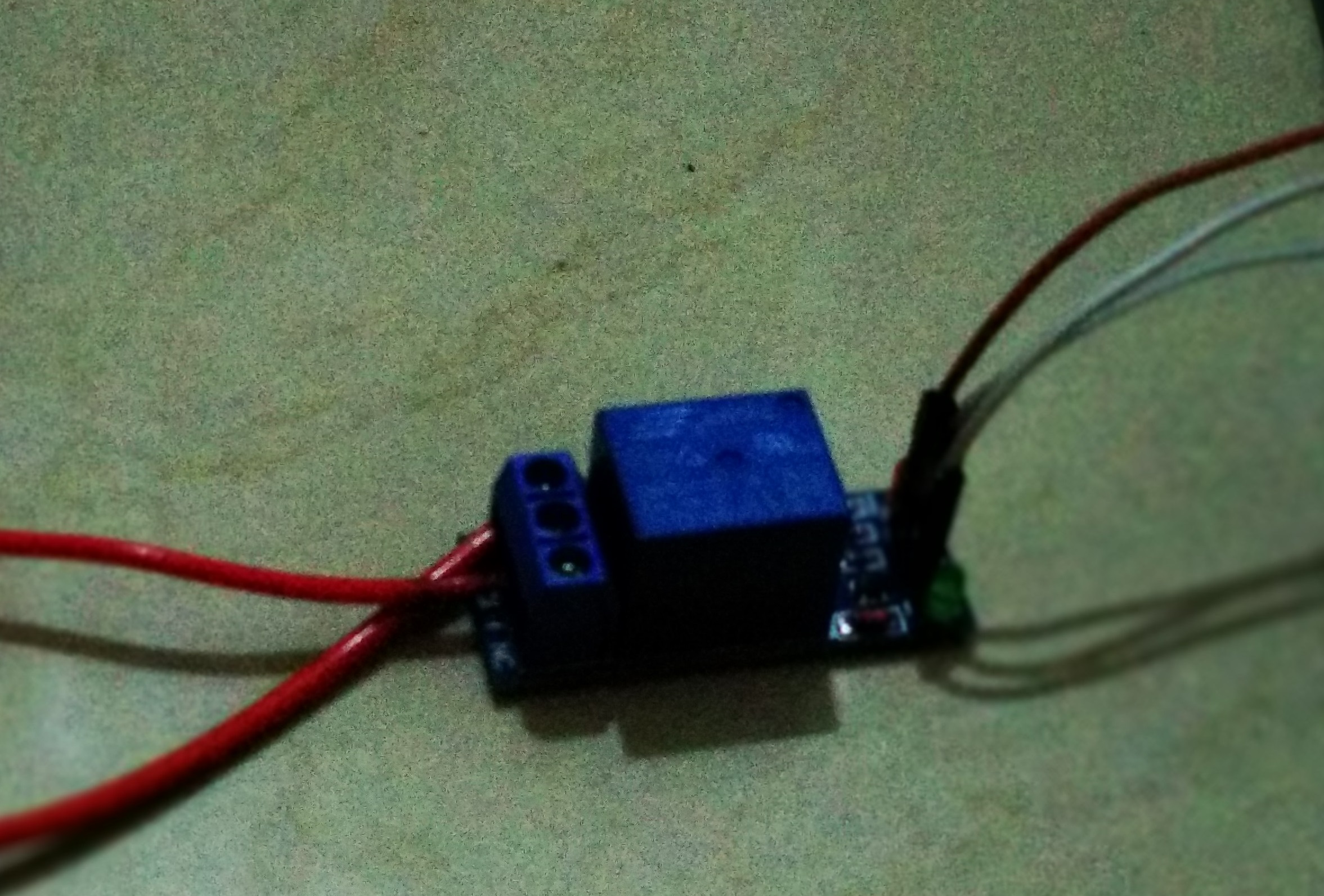
3) Relay module: I have use single channel 5V relay module here. It has 3 pins for connection with Arduino and 3 ports to connect devices. Vcc pin is used to power relay with 5V, a Ground pin, IN pin for digital input. 3 ports are COM(common), NO(normally open), NC(normally closed) to power the devices (e.g. light bulb).
4) Jumper Wires: For connection with Arduino. You can buy set of male to male, female to female, male to female jumper wires from amazon or any other marketplace of your chioce.
5) AC Bulb, Light bulb socket and electric wires: For connection of socketwith relay module. You can easily find these items in your house or nearby shops.
Configuring Blynk App
1) Open and login to Blynk app.
You will get 2000 energy balance which will be used to add widgets. This energy is renewable on deleting a widget but you will not get it back if you share it. So consume it wisely.
2) Create 'New Project' and name it whatever you want.
3) Choose 'Arduino Uno' from device list and Connection type as 'WiFi', choose your theme and click on 'Create'.
4) You will recieve an E-mail with your authorized token. Kindly note it down.
5) Now click on + sign on the top and add one Button.
6) Click on button and set the output pin to 'Digital' and 'D7'. Set pin values to 1 and 0 respectively. (Question may arise in your mind here why I have set it to (1,0) not (0,1)? Well, I have explained that in Step 6 of this Instructable). Set switch mode to 'Push' and name all labels as you like.
7) Again click on + sign and add Text Input.
8) Click on Text input and set 'Output' pin to V0, 'Character limit' to 5 and you can name other fields as you like.
9) Open command prompt on your PC with active Internet connection and type following command:
ping blynk-cloud.com
Note down the IP address which looks something like this
188.166.206.43
It is the IP address of blynk server for your country.
Now move to next step for creating IFTTT applet.
Creating IFTTT Applet
You might have already created your account on IFTTT.com or on IFTTT app. If not, then please create it.
Steps for creating IFTTT applet for Google Assistant:
1) Follow the tutorial mentioned in below link along with the steps I am mentioning here:
2) Creating Trigger:
i) Search for Google Assistant in search bar while creating trigger.
ii) Select 'Say a phrase with a text ingredient'
iii) You can enter three ways to say your phrase. Enter your phrases with text ingredient. For example I have entered 'turn $ lights'. Here, whatever i will say in place of $ will be the text ingredient. Also enter the phrase you want to listen from your Google Assistant.
iv) Select language and click on Create trigger.
3) Choose Action:
i) Search for Webhooks in search bar while choosing action.
ii) Click on 'Make a web Request'.
iii) Place following in URL field:
http://"ip address from previous step"/"Your auth token"/pin/"Pin Number of blynk text input"
Insert your IP address, auth token and Pin number (i.e.V0 or whatever pin number you set for text input in blynk app) without the double quotes.
iv) Set 'Method' to PUT, 'Content type' to application/json and copy following into 'Body'
["{{TextField}}"]4) Click on Finish and move to next step.
Working
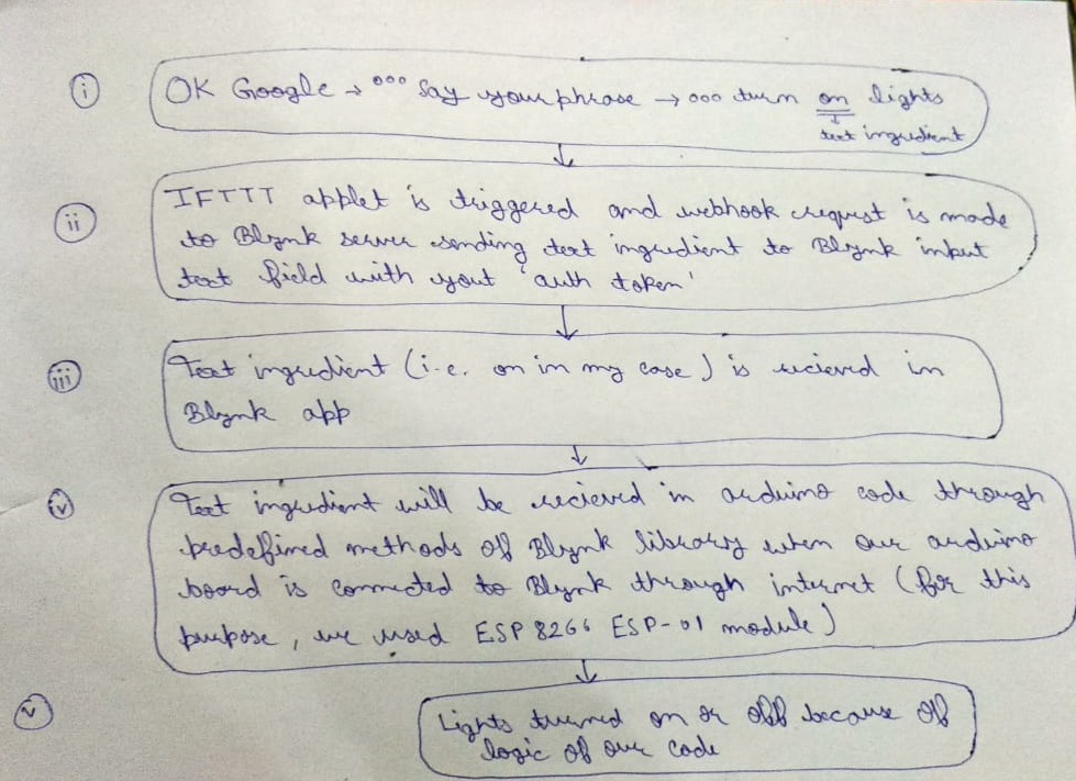
The working is quite easy as you can see in the picture, when we say "OK Google" and give command to Google Assistant "turn on lights", the IFTTT applet will be triggered and "on" will be passed as text ingredient to blynk app. Blynk app receives it in input text field and we get it in arduino code using blynk library <SPI.h> method param.asStr(); When "on" is received then digital pin D7 of arduino board will be set to 0 and lights will be turned on and when "off" is received then digital pin D7 of arduino board will be set to 1 and lights will be turned off (again same confusion from step 3.... right! Don't worry I have explained it in next step.)
Connections
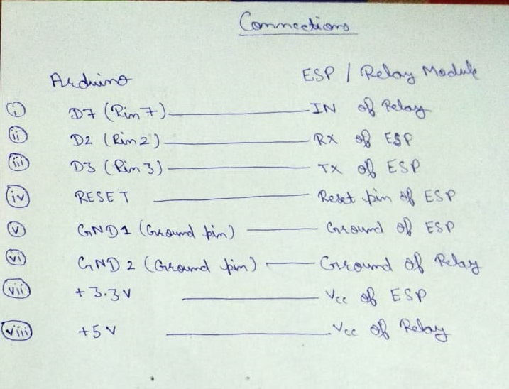
The question might have arose in your mind that "why I set pin 7 of Arduino board to 0 for high input and 1 for low input of relay module?"
The answer is simple because the relay module I am using is active low which means that relay is active when input is 0 and inactive when input is 1. But why it is this way? This is because when Arduino boots then all output pins of Arduino are set to high by default which will set the relay to active at start. So, to set the relay to inactive at the beginning, it is made active low.
Now lets check out the connections.
I have made the connections between pins of Arduino, ESP8266 and Relay module in the above picture. I have also mentioned the connections below because I know how great my handwriting is:(
Pin diagram of ESP8266 ESP-01 is shown in step 2.
Connections between Arduino,ESP8266 and relay module:
Arduino <-----------------------------------------------> ESP/Relay
Pin 7 ------------------------------------------------------- IN of relay
Pin 2 -------------------------------------------------- RX pin of ESP
Pin 3 -------------------------------------------------- TX pin of ESP
RESET-------------------------------------------- RESET pin of ESP
GND 1 -------------------------------------------- Ground pin of ESP
GND 2 -------------------------------------------- Ground pin of relay
+3.3V ------------------------------------------------------ Vcc of ESP
+5V ------------------------------------------------------ Vcc of relay
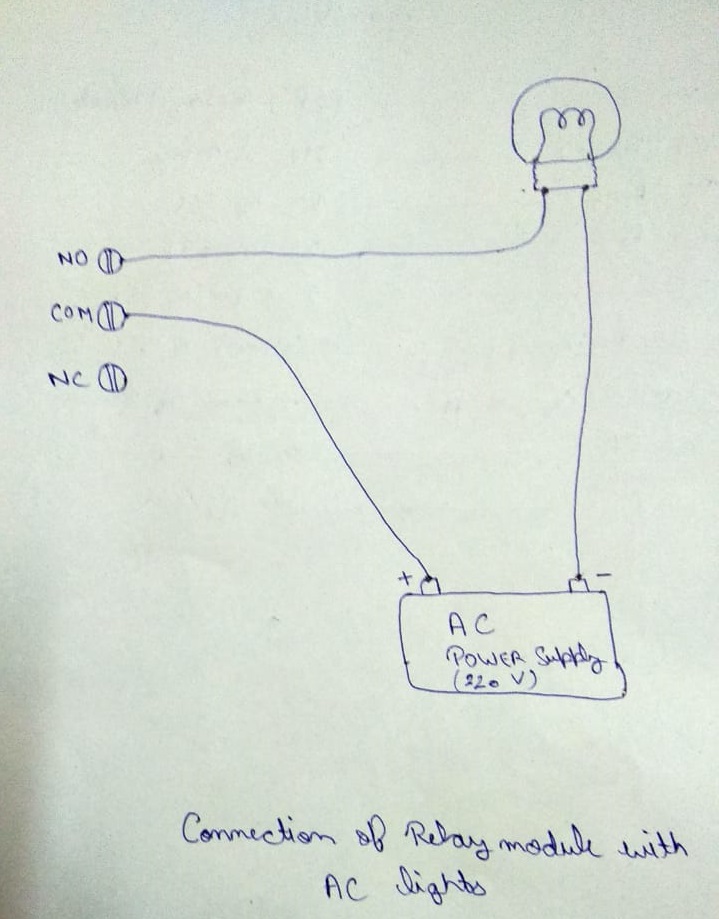
Connections between second end of relay module and AC lights:
NO (normally open) of relay ----------------------> any one end of bulb socket
COM (common) of relay ---------------------------> +ve end of AC supply
remaining end of AC supply------------------------> remaining end of bulb socket.
NC (normally closed)----------->leave as it is.
(Please refer to above diagram for better understanding)
Uploading Code and Testing With Google Assistant
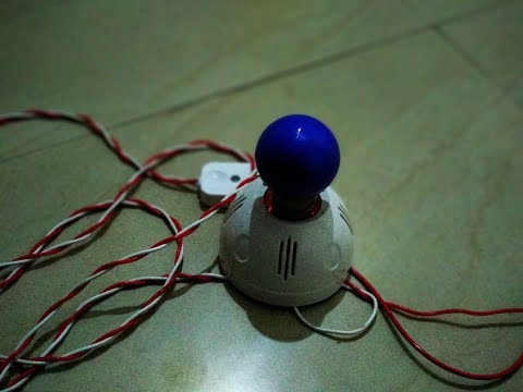
1) Open 'Arduino IDE' on your PC
2) Open below sketch in IDE
3) Replace auth token, WiFi ssid and your password with your credentials.
4) Upload the code to Arduino board. (It is always best practice to upload the code to idle Arduino board and connecting sensors after successful uploading)
5) Open Blynk app and turn on your WiFi hotspot.
6) Click on the play button on the top right of Blynk app to run the project.
7) You will be notified as soon as the connection is established.
8) Now its time for the real thing. Say "OK Google" in your phone, wait for Google Assistant to open and now speak your phrase like "turn on lights", in few seconds Google Assistant will respond to you with the phrase you entered to be listened from Google Assistant in IFTTT such as in my case is "lights turned on"
9) Say "turn off lights" to turn them off. You can also control your lights via Button in Blynk app.
Congratulations! Your lights are now operating with your voice.