Control ESP8266 From Google Home Using GBridge.io
by FrancisP43 in Circuits > Wireless
33508 Views, 21 Favorites, 0 Comments
Control ESP8266 From Google Home Using GBridge.io
There are different ways to control ESP8266 from Google Home, but most of the solutions you can find on Internet use IFTT, which is not really user-friendly to setup.
gBridge.io allows to make the process easier and act seamlessly.
In this how-to guide, I’m gonna show you how I setup my ESP01 module to answer to commands such as “Turn the lamp on” and “Is the lamp turned on?”. The project only turn on and off the built-in LED, but it easy to go further after that.
Materials needed:
- 1 * ESP8266 module (https://www.sparkfun.com/products/13678)
- 2 * push-buttons (https://www.sparkfun.com/products/97)
- 1 * 10k resistor
- 1 * FTDI cable 3.3V (https://www.sparkfun.com/products/14909)
FTDI Cable to ESP8266
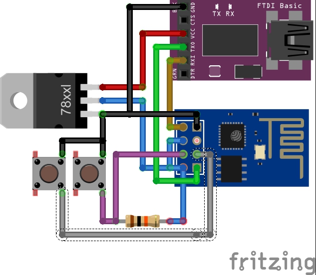
To communicate between ESP8266 and your PC, wou will have to make a FTDI to ESP8266 adapter.
- You will have to build the circuit shown in the linked image if you have a 5V FTDI cable:
- If you have a 3.3V FTDI cable, you can avoid the 78xxl chip, and plug 3.3V directly to ESP8266.
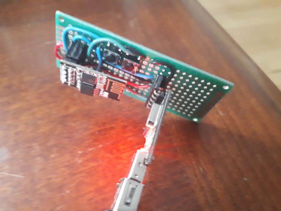
- The left button is the “programing” button and the right one is the “reset” button
- When you want to put it in “programing” mode, you have to keep the two buttons pressed and first release the reset button, and after that, the second one.
- The program button will be used in this project to turn on and off the built-in LED manually.
Programing ESP8266 With Arduino IDE
The second step is to be able to program ESP01 module with Arduino IDE. This will make it easy after that to use the MQTT Library from Adafruit. I was inspired by this guide for these steps: http://www.whatimade.today/esp8266-easiest-way-to-program-so-far/
- Install the latest Arduino IDE version. In my case it was v1.8.8.
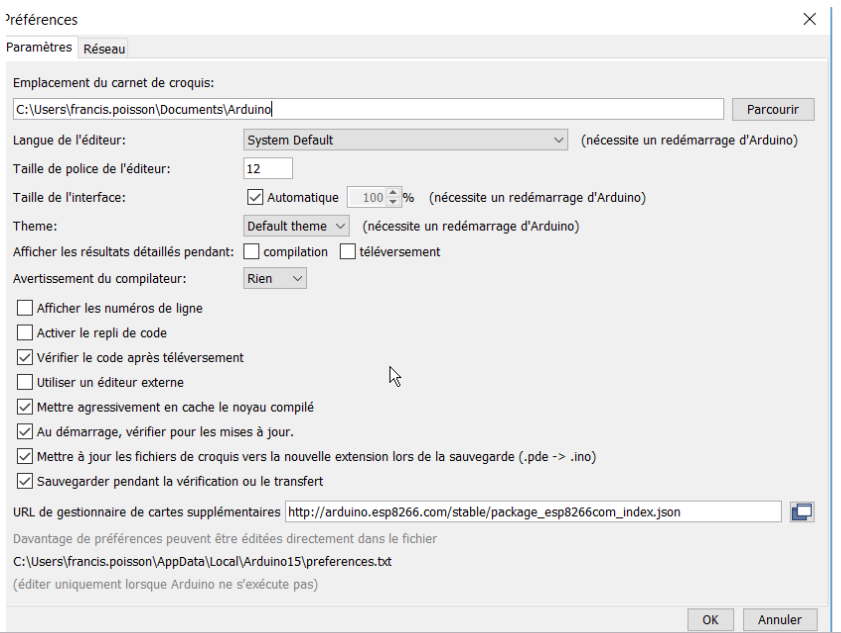
- Go to File --> Preferences and add the link http://arduino.esp8266.com/stable/package_esp8266com_index.json to the Additional Boards Manager URLS.
- Go to Tools --> Board --> Boards manager
- You should now have the esp8266 as an option there since you've added it to the Additional Boards.
- Select it and press Install.
- You should now have ESP8266 module listed as “Generic ESP8266” module.
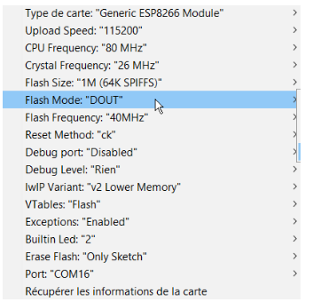
- In my case, I had to choose some parameters as shown in the linked image.
- Choose the Port where your FTDI cable is plugged.
- You can test the “Blink example” (File --> Examples --> ESP8266 --> Blink).
- Put your ESP8266 in “programing” mode by keeping the two buttons pressed and first release the reset button, and after that, the second one.
Setting Up GBridge

- Go to https://about.gbridge.io/
- Register an account
- Login to your account
- Create a new device
- Press Add.
In your device list, you should have your new device listed.
You will need the two feeds address for later.
To connect Google Assistant, you can follow the guide available in gBridge documentation: https://doc.gbridge.io/firstSteps/gettingStarted.html
Getting Adafruit MQTT Library to Work With GBridge
The Adafruit MQTT library will be used to communication between the ESP866 and gBridge.io
- In Arduino IDE, Go to Tools -> Library Manager
- Install Adafruit MQTT Library
- Enter informations in the first part of the code and upload it. You shoud be up and running.
/************************* WiFi Access Point *********************************/
#define WLAN_SSID "Your SSID name"
#define WLAN_PASS "Your SSID Password"
/************************* Gbridge Setup *********************************/
#define AIO_SERVER "mqtt.gbridge.kappelt.net"
#define AIO_SERVERPORT 1883 // use 8883 for SSL
#define AIO_USERNAME "your gBridge username"
#define AIO_KEY "your gBridge password"
/****************************** Feeds ***************************************/
Adafruit_MQTT_Publish onoffset = Adafruit_MQTT_Publish(&mqtt, "gBridge/u341/d984/onoff/set"); //Replace by your feedname
Adafruit_MQTT_Subscribe onoffbutton = Adafruit_MQTT_Subscribe(&mqtt, "gBridge/u341/d984/onoff"); //Replace by your feedname