Control Any Devices Using Raspberry PI and PCF8574, Relay Module
by adachsoft in Circuits > Raspberry Pi
20157 Views, 75 Favorites, 0 Comments
Control Any Devices Using Raspberry PI and PCF8574, Relay Module
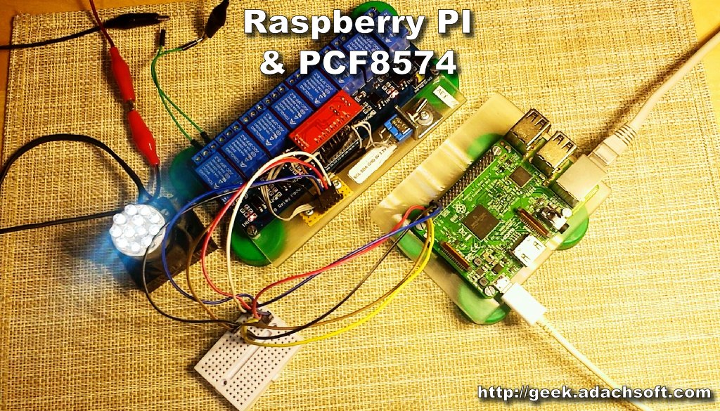
This guide shows you how to use PCF8574 with Raspberry PI. The PCF8574 is a 8 bits I/O port expander that uses the I2C bus. To the PCF8574 I will connect the relay module, this will allow control of the electrical device from the Raspberry PI. I will also show an example how to write a program to handle PCF8574 in C++ on Linux.
This article can also see here:
Control any devices using Raspberry PI and PCF8574, relay module

Components
Components I used in this example.
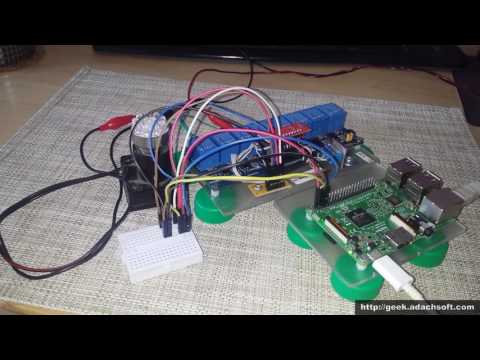
Schematic
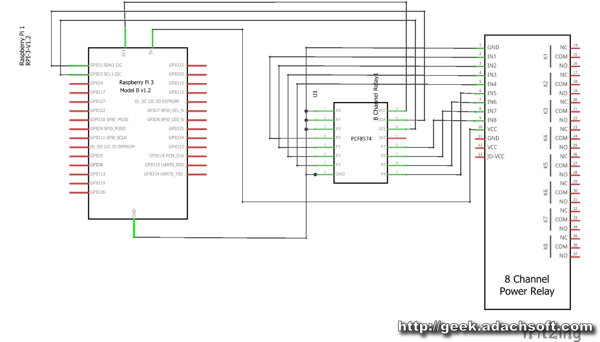
Diagram of connecting Raspberry PI with PCF8574 8bits I/O expander.
Enable I2C Interface on the Raspberry Pi
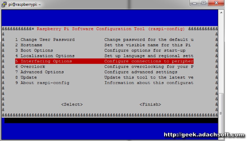
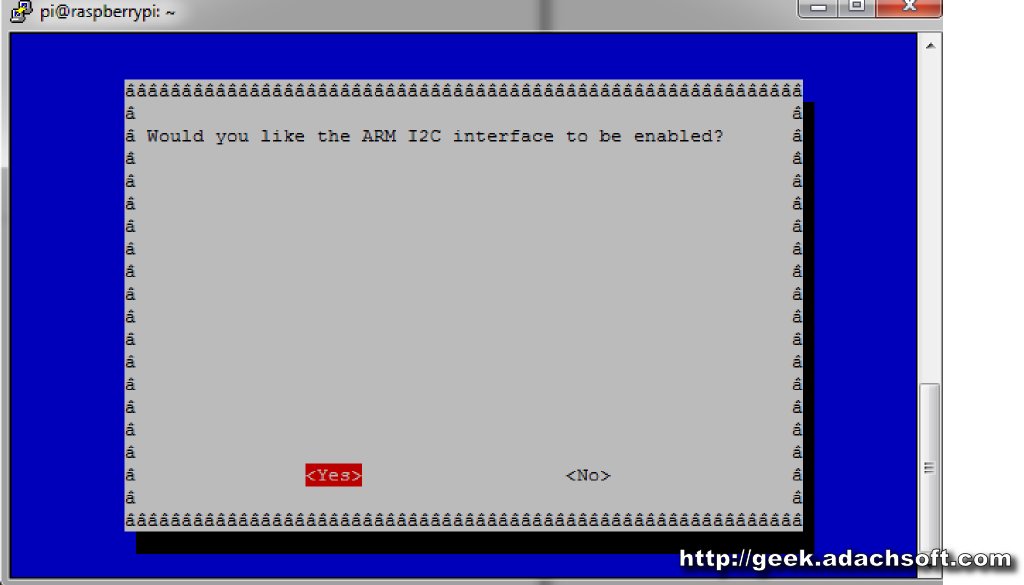
At first we need to enable I2C bus on Raspberry Pi. For this purpose, we use the following command.
sudo raspi-config
- Select Interfacing Options
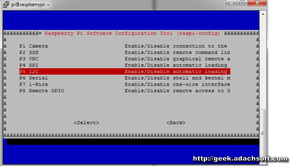
- Select P5 I2C
- Select Yes
Install Utilities
	sudo apt-get update
	sudo apt-get install -y i2c-tools
We add user pi to group i2c.
sudo adduser pi i2cAfter installation we restart the Raspberry Pi.
sudo shutdown -r now
Checking I2C Bus and PCF8574
First, let's scan the i2c bus. In this step, you must already have a PCF8574 connected,
otherwise the scanner will not find anything.
0x38 is the address of the PCF8574 expander.
0xf0 is the output state as we set, 4 bits in HIGH and 4 bits in LOW.
otherwise the scanner will not find anything.
i2cdetect -y 1My PCF8574 has an address 0x38. Now let's test the expander.
0x38 is the address of the PCF8574 expander.
0xf0 is the output state as we set, 4 bits in HIGH and 4 bits in LOW.
i2cset -y 1 0x38 0xf0We can also read the state of PCF8574 I/O ports.
i2cget -y 1 0x38
Software
Below simple program to handle PCF8574, written in C++.


#include <stdio.h>
#include <time.h>
#include <string>

#include <wiringPi.h>
#include <pcf8574.h>

using namespace std;

int main (int argc, char *argv[]){
	printf("Raspberry Pi\n");
	printf("http://geek.adachsoft.com/\n");

        wiringPiSetup();
	pcf8574Setup(100, 0x38);

	for (int i = 0; i < 8; ++i){
    		pinMode(100 + i, OUTPUT);
	}

        int b=0;
        while( 1==1 ){
                printf("LOOP %u\n", b);
                for (int i = 0; i < 8; ++i){
                    digitalWrite(100 + i, i==b ? 0 : 1);
                }
                b++;
		if( b >= 8 ) b=0;
		delay(1000);

	}

	delay(1000);
	digitalWrite(100 + 0, 0);

	delay(1000);
        digitalWrite(100 + 0, 1);

	return 0;
}
To compile and launch it, use the following command. g++ pcf8574.cpp -o pcf8574 -lwiringPi -std=c++11 ./pcf8574Download source code: pcf8574.cpp