Contoured Topography Module
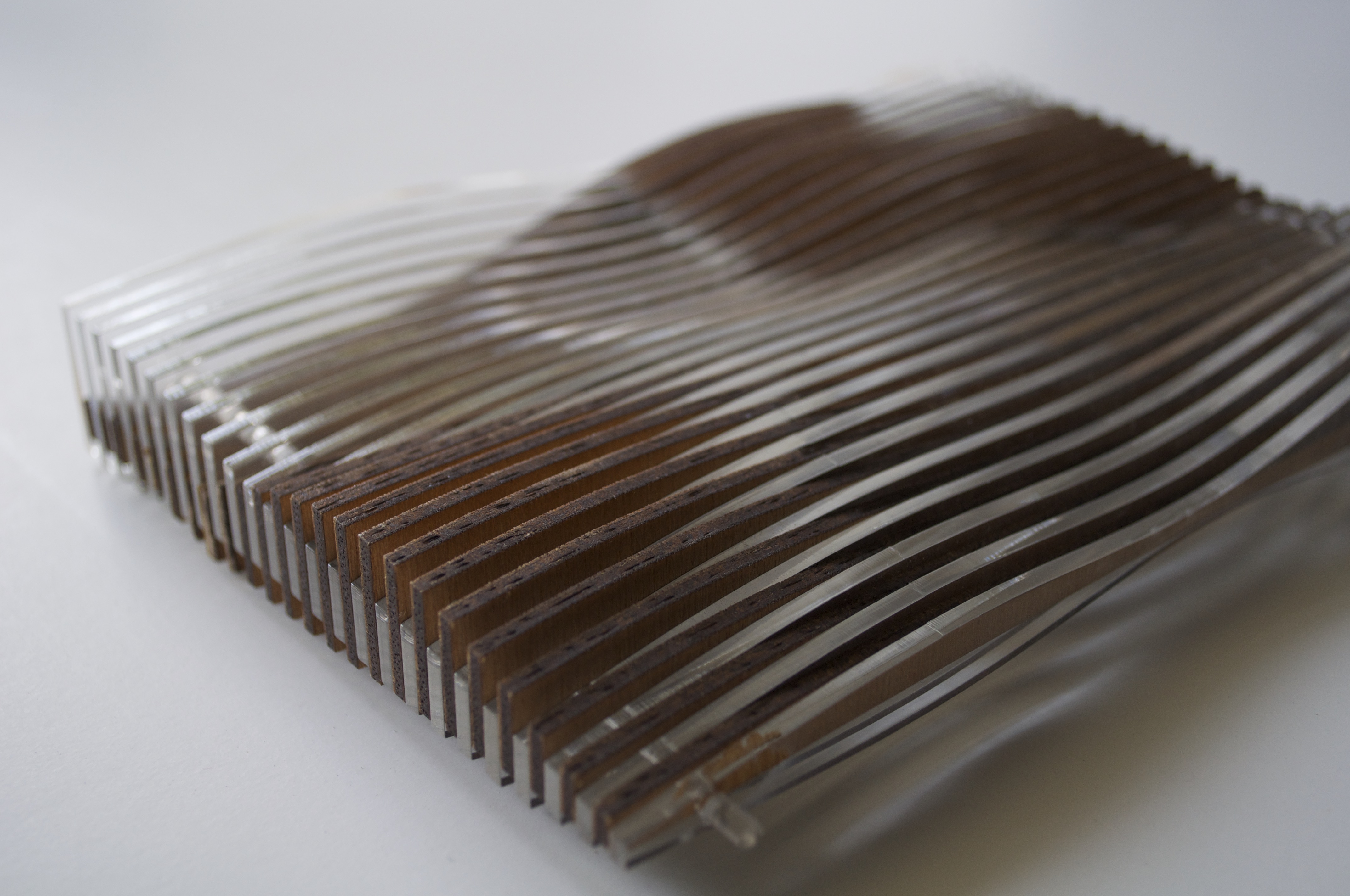
This module was a study I had done simply to visualize contrasting elements of nature at their convergence. My original intention was to represent the overlap and change of land/sea, but during the process, I came to realize that the method had the potential for many other applications. With the use of two different materials, the model can be anything from earth/vegetation, figure/ground, interlocking textures, or even movement.
The beauty of it is in it's adaptability and simplicity of fabrication. The technique can be altered to any scale (furniture, walls, landscapes) and any material, and requires very little to come together.
The 3D model was built in Rhino, and production requires a laser cutter.
Materials (specific to this iteration):
- 1/8" clear acrylic
- 1/8" wood or board
- 1/8" acrylic rod
Establishing Layout
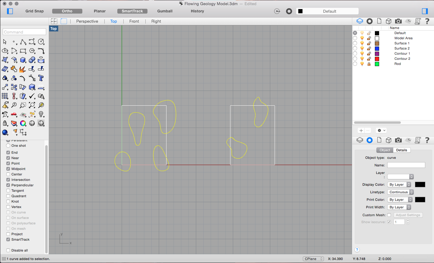
Determine the size of the unit. I have it here as a 6"x8" module, but there should be no limitations to size or shape as long as you have the materials and means of fabrication.
Draw two rectangles to outline the two terrains to be made. Within the confines, establish curves for the topography. I experimented with several simple shapes in different locations to really get a contrast between the two materials.
For more deliberate studies, the topography can be traced from an underlay of an existing map or imported from a drawing.
Drawing Topography
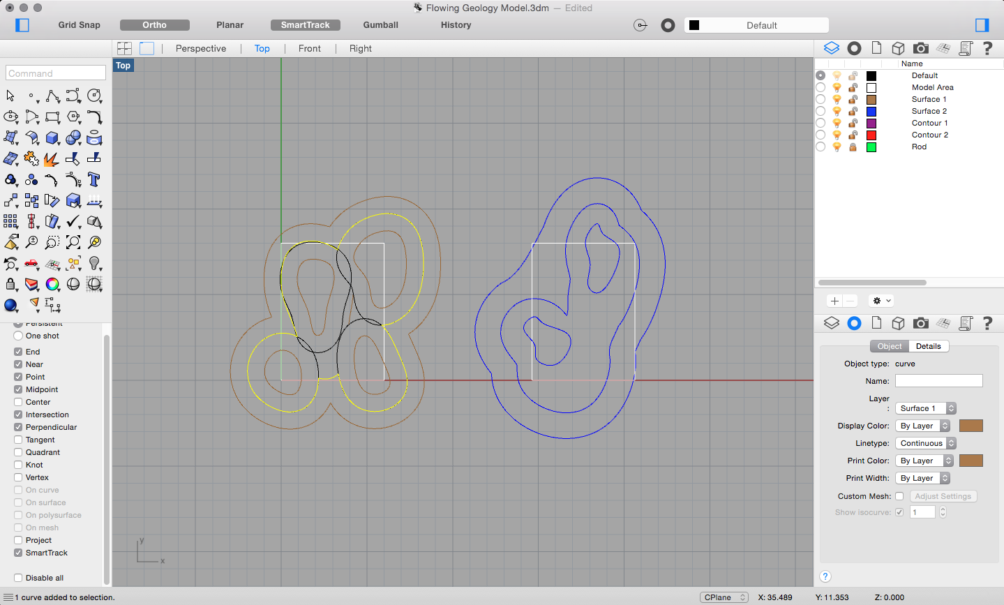
Once the points are established, begin to offset the curves to make topography lines. For Surface 1 (in brown), the offsets are in black and the highlighted yellow is the resulting curve. Keep in mind that the offsets do not have to be regular. Again, the shape of the topography is at your discretion.
Continue drawing contour lines until the extents of the rectangle are reached, and in an elevation view, raise them to the desired height. I've moved mine in 1/4" increments.
Patching Surfaces
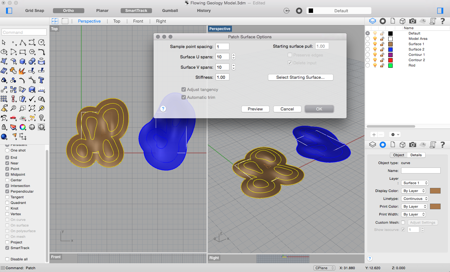
Once all of the elevations are set, highlight all the contour lines of the first surface and use the command "Patch". The default values that appear in the box are good to go (you may adjust them as you wish). Hit OK, and your 3D surface should be created.
Repeat this for Surface 2.
Forming a Volume
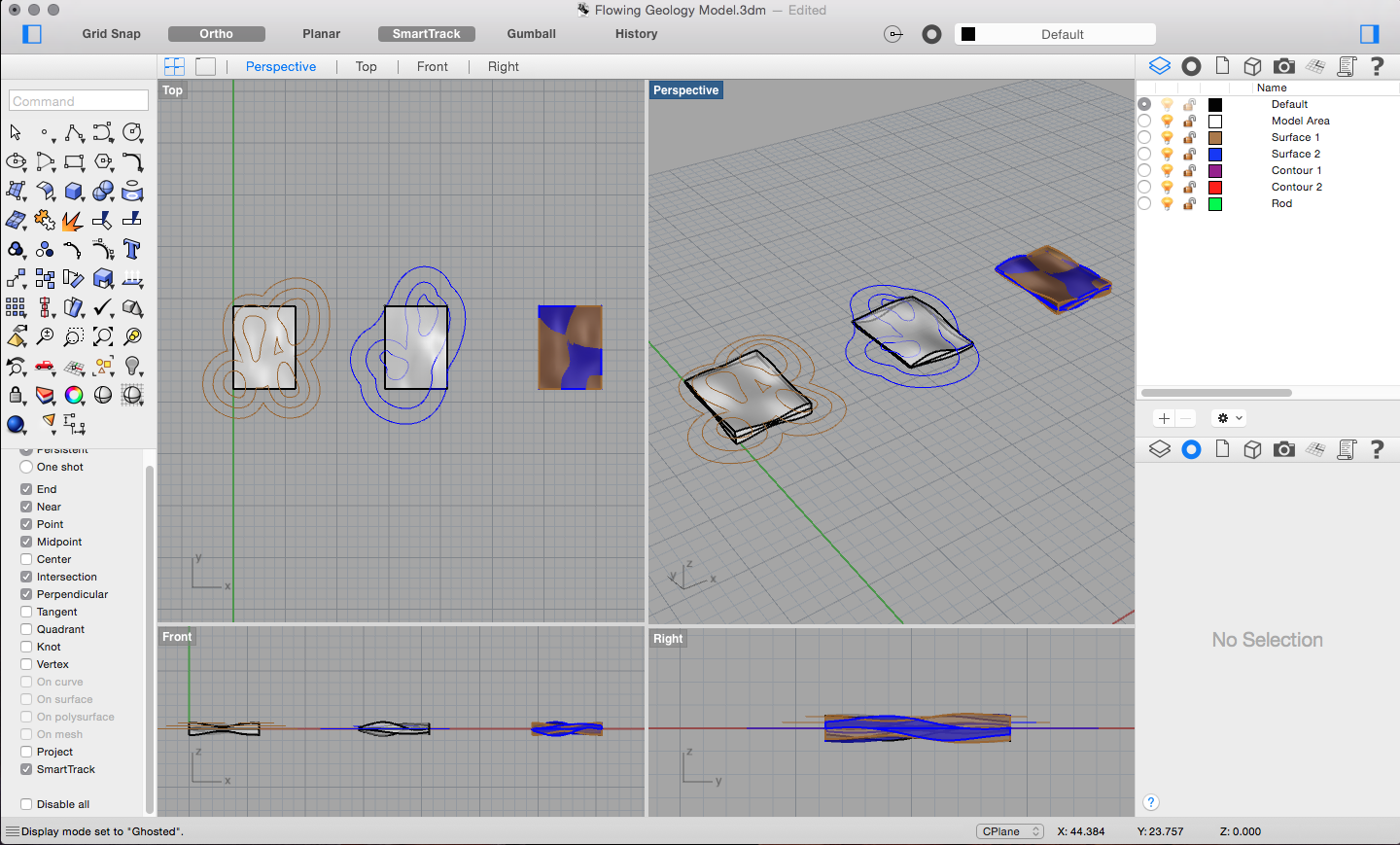
Use your existing outline to "Trim" the surface to the designated size.
At this point, we only have sheet-like surfaces. To create a volume, I mirrored the surface along the x-axis and closed off the edges. Feel free to play around with the orientation of the mirrored surface, like rotating it 180 degrees or adjusting the thickness of the volume.
The two white solids are the two separate terrains, and the third object shows how they would look when overlapped.
Creating Contours
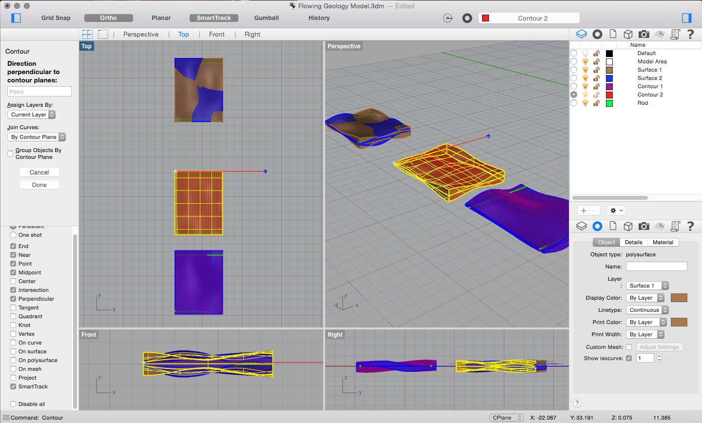
Before creating the contours, model the rods that will be holding the module together (shown in green). This can be done by extruding a circle the size of your rods and placing them perpendicular to the contour cuts at each end so that they are completely embedded within the depth of the volumes.
With the "Contour" command, cut perpendicularly through the width of the volume. The increments should be the thickness of the material that you have. Since we are alternating two materials, however, we will only need contours for every other cut. Here, because I have wood and acrylic both at 1/8" thickness, I will contour them at 1/4", with the slices beginning 1/8" apart.
Draw the contours on a different layer to make them more easily accessible for editing.
Cleaning the Contours
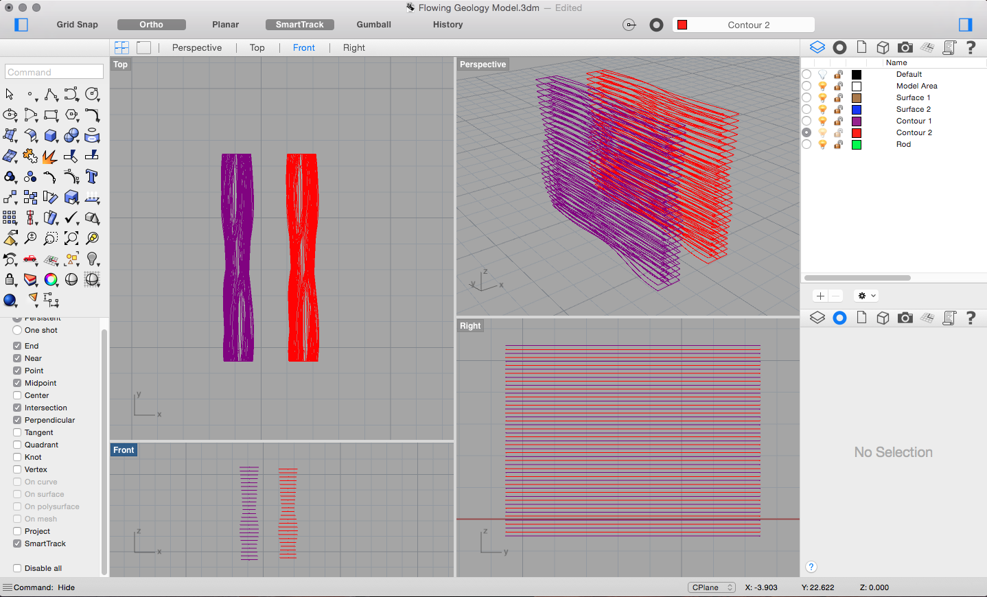
Disassociate the contours from the solid, since this is what we will be using for cutting. Clean the lines by making sure they are all joined at the edges. Check that you also have the contours of the rods on each slice. Also check that the contours for the two volumes are alternating.
Preparing to Cut
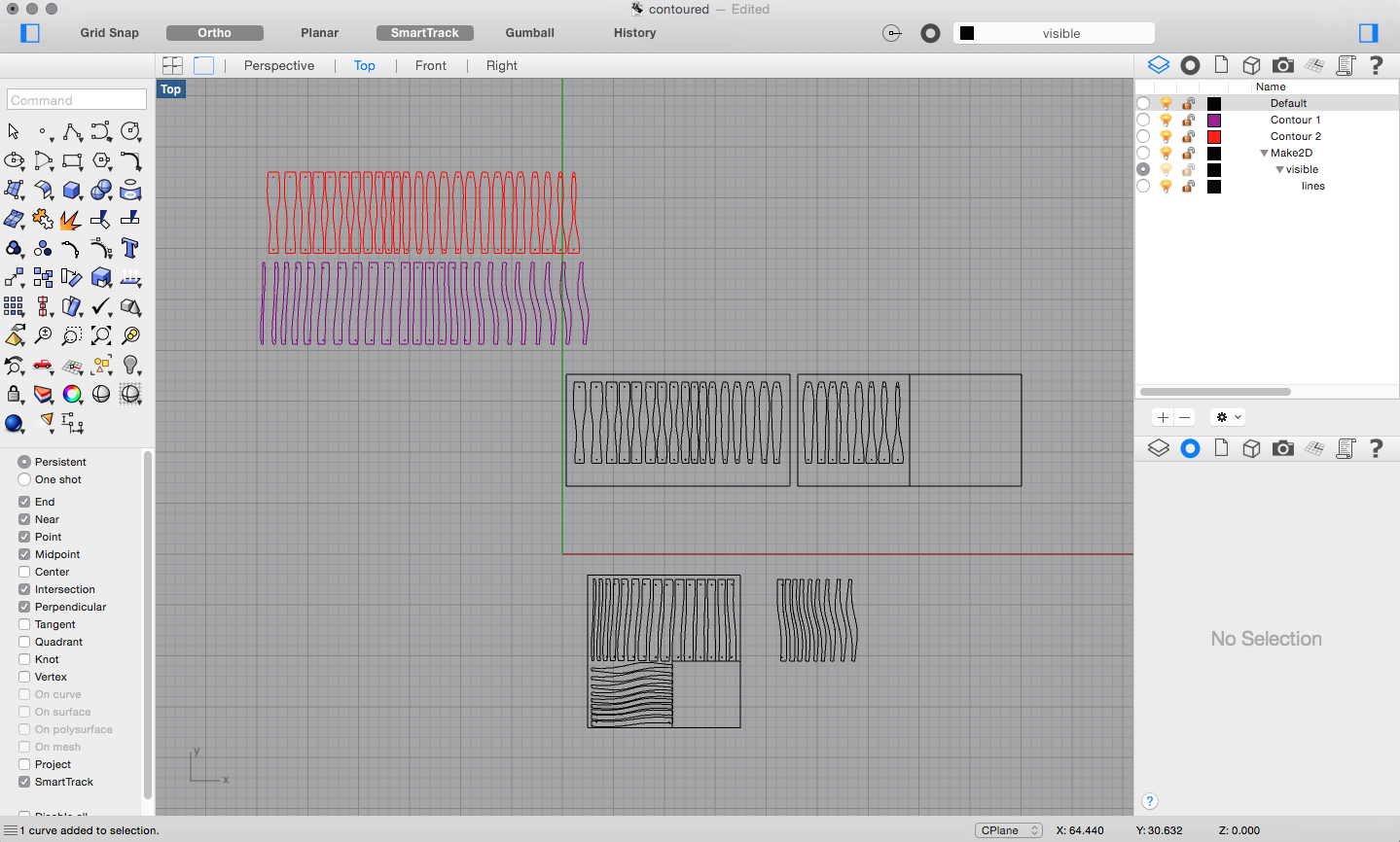
Copy the line work into a new Rhino file, or whatever the laser cutting machine prefers. An easy way to keep track of the order of the contours is to add a small number on the end of each piece that the machine can etch.
Lay out the contours according to the sheet of materials you have and let the machine run!
Assembly
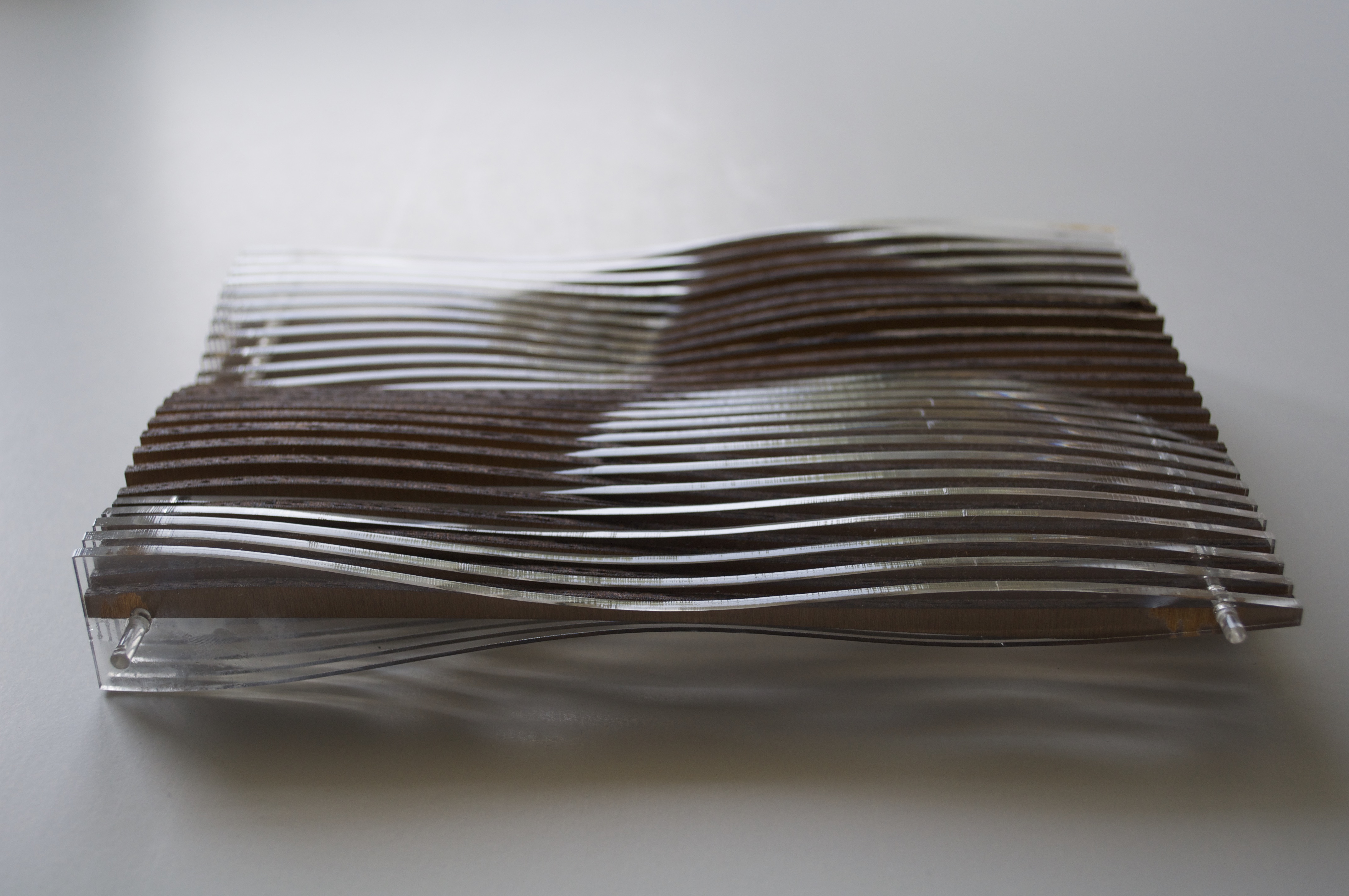
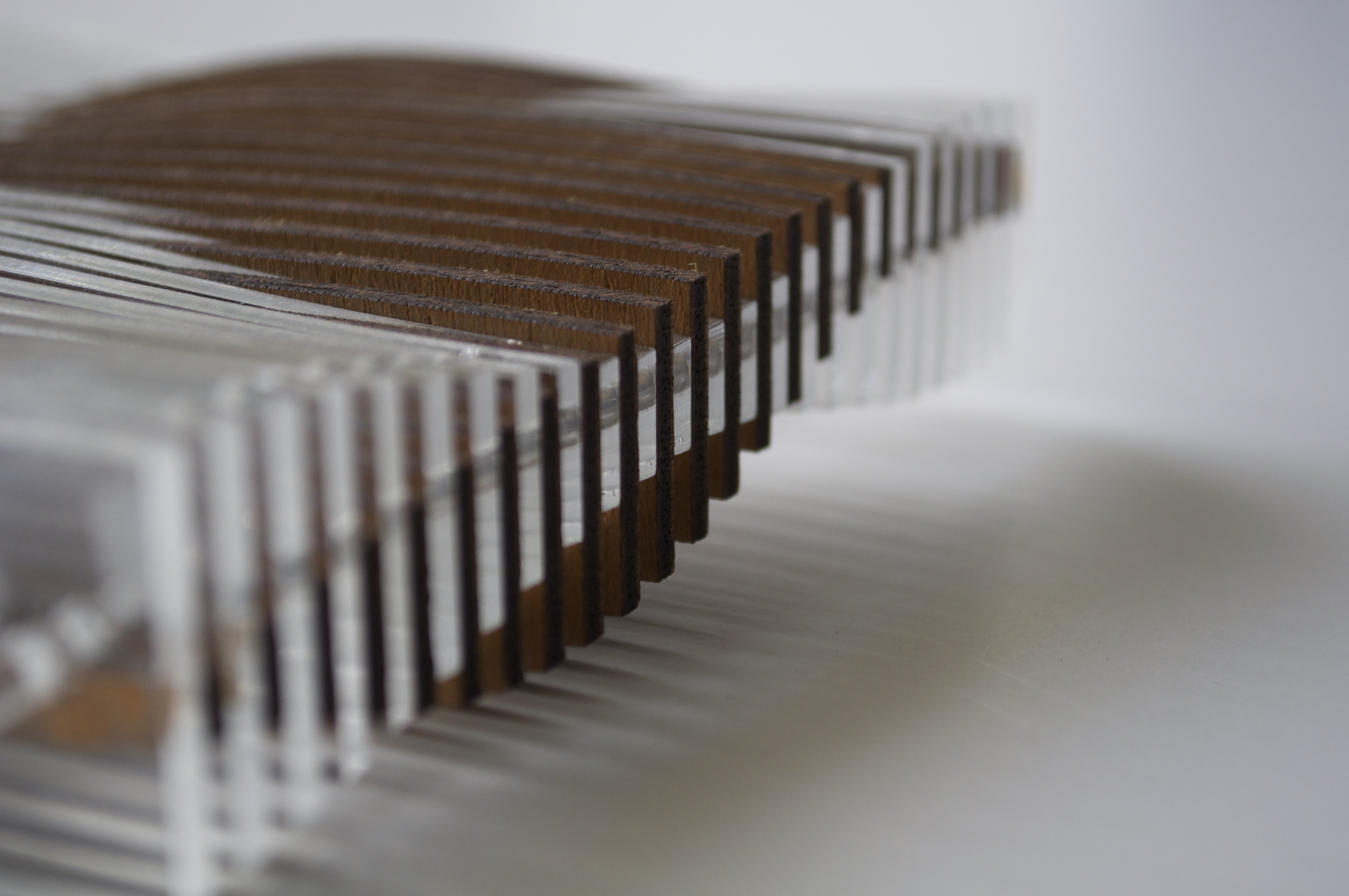
One by one, slide the rods in order into each contour. They should fit snugly and require no glue.
The module gives it the flexibility to be multiplied, stacked, lengthened, etc.