Connecting Old Proform TDF Bike to Zwift Part 2
by Old_Tekkie in Circuits > Arduino
1567 Views, 4 Favorites, 0 Comments
Connecting Old Proform TDF Bike to Zwift Part 2
NOTE: The Zwift upgrade of December 2021 caused the incline controls of this project to fail. As of January 5, 2022 this has been resolved with revised code for the ESP32.
This is the second part of the instructable Connecting TDF Bike to Zwift where I described how to connect an old Proform TDF Generation 2 TDF bike to virtual cycling games like Zwift and RGT using an Arduino Nano 33 BLE microcontroller. In part 1, the bike was only able to provide input to the game such as power and pedal cadence to facilitate riding along with the game. There was no feedback from the game to the bike so you had to manually apply incline resistance by using the controls on the bike to match the incline displayed by the game.
This instructable adds control from the game to automatically activate the bike's incline buttons (up and down buttons) to match the terrain encountered as you you ride through the virtual worlds. This is done by using a second microcontroller, this time an ESP 32 (WEMOS TTgo D1 R32 ESPDuino-32) connecting to Zwift via bluetooth and controlling the TDF Bike via solenoids mounted over the bike's control buttons.
This solution is not perfect as it merely provides a solenoid pulse to increase or decrease bike incline according to the game terrain. As no feedback of the bike's actual incline is provided to the microcontroller occasionally a solenoid pulse may be missed by the bike's control buttons and the bike incline may get out of sync with what the game displays. This is easily remedied by tapping the top of the solenoid over the appropriate incline button to bring the game back to sync with the bike. My experience shows the solenoid activation is approximately 95% effective on button activation, that is to say, for every 100 incline changes required by the game, you may have to manually tap the solenoids 5 times. I have added an optional display to provide an instantaneous reading of game incline and microcontroller incline. If the bike incline from the TDF display incline does not match the microcontroller incline, then a "tap" on the solenoid is required. Alternatively the game incline display can be used, but I have found there is a time lag between the game display and what is being fed to the microcontroller over bluetooth which may cause you to manually adjust incline unnecessarily.
This project is largely based on the instructable Zwift Interface for Dumb Turbo Trainer by Peter Everett. Most of the code running the ESP 32 is his design, especially the code for the bluetooth FTMS portion of which I am most grateful and personally have limited understanding. Without his project I would not have had a clue of where to start. Thank you Peter! Please read through his instructable as he provides a lot of detail on assembly
Supplies
ESP 32 (WEMOS TTgo D1 R32 ESPDuino-32)
5 volt 1 Amp USB charger with type C cable to power the ESP 32
12 volt 1 Amp power adapter to power the solenoids
TIP 120 Power Darlington Transistor QTY 2
1K Ohm resistor 1/6 Watt QTY 2
2 x 16 Character LCD Display (Optional)
I2C Interface for Display (Optional)
Angle iron for mounting solenoids
Gorilla Super Glue for mounting the solenoids
22 - 24 Gauge Hookup wire (various colors- can be stripped out of old data cables)
2x 4 foot lengths of 8 conductor data cable
2 inches of sticky sided velcro (both hook and loop sides)
2x #8 by 3/4 inch bolts and nuts
6x nylon tie stra
hot melt glue
rosin core solder
electrical tape
I have discovered there are many different flavors of ESP32 boards out there. The particular board I used and linked to in the parts list above is a clone board. The software and instructions following work with this particular board. Other boards may require different pin mapping within the software and wiring connections to pins.
Step 1: Program the ESP 32
The ESP32 is programmed using the Arduino IDE. You need to have the ESP32 tools installed - instructions are here: https://github.com/espressif/arduino-esp32 .
To summarize:
Install the the Arduino IDE at the 1.8 level or later. The current version is at the Arduino website.
Start Arduino and open the File > Preferences window.
Enter this link into Additional Board Manager URLs field:
https://dl.espressif.com/dl/package_esp32_index.js...
Open Boards Manager from Tools > Board menu and install esp32 platform (and don't forget to select your ESP32 board from Tools > Board menu after installation, in this case ESP32 Arduino > ESP32 Dev Module).
You will also need the Neil Kolban's ESP32 BLE Arduino Library and the Blackhawk LCD_I2C library which can be installed from the Tools > Manage Libraries in the Arduino IDE.
To upload the code plug the ESP32 into a PC using the USB connection, select the board and virtual COM port in Arduino and click compile/upload.
The code is attached as the file LCDTDFResetControl7final.ino.
Within the code I have fixed the maximum incline to 10 percent and maximum decline to 5 percent. For my personal riding I find that this is the limit of my personal ability for incline power. Any more than 5 percent decline appears to be meaningless as far as speed or power are concerned from a game perspective. This can easily be changed by modifying the following variables. Note the bike itself has a range of +- 20 percent.
const int upperInclineClamp = 10;
const int lowerInclineClamp = -5;
Downloads
Step 2: Wire the ESP32
This system has 3 main components:
1) The ESP32 controller which communicates with the game via bluetooth.
2) The solenoids which activate the incline buttons on the bike and are controlled by the ESP32 controller
3) An optional display to provide the rider with feedback as to what grade the ESP32 controller "thinks" the bike is at and the actual value of the grade the game is providing to the ESP32 to 2 decimal places.
In my case I mounted the ESP32 near the front base of the bike beside the Arduino Nano from part 1 of this project. The wiring is run from the ESP32 up to the bike handle bars and bike console to connect to the solenoids and optional display.
The ESB32 board itself is powered by a 5V USB power supply from a cell phone charger via a USB C connector. The board will control two power transistors which in turn will control two solenoids. The solenoids each have a 1N4005 diode connected across them in a reverse bias configuration acting as a voltage snubber to protect the transistors and microcontroller from transient voltages produced by the solenoids. These solenoids will be glued to a piece of angle bracket mounted over the incline buttons of the TDF Bike. The solenoids require between 9 and 12 volts (preferably 12 volts) at approximately 1 amp to strike the buttons hard enough to reliably control the bike. Even though the solenoids are rated at 5 volts, using a 12 volt supply is not an issue as the solenoids will only be activated for 275 msec at a time. This strike time appeared to be the sweet spot between missed pushes and double pushes. I have also limited the maximum activation interval at once per second. This ensures that the solenoids will never reach a failure temperature.
As described earlier, sometimes when the solenoid activates, the bike fails to register the button push. This appears to have a few causes:
1) The solenoid did not strike hard enough or the solenoid is mispositioned over the incline buttons.
2) The integral bike controller was busy doing something else (raising and lowering bike) and failed to register the incline button push.
3) The integral bike controller was distracted by a gear change and failed to register an incline button push.
The result of a missed solenoid strike/ button push is that the ESP32 will think that the bike is at an incline that it is not. For example the ESP will strike the up solenoid to command the bike to go from 3 to 4 percent. The bike will miss the button push and stay at 3 percent. The ESP32 has no way of knowing the bike didn't move so it "thinks" the bike is at 4 percent where it is only at 3. Since both the Zwift and RGT games provide a display of the current grade, the rider can manually tap the appropriate solenoid to resync the ESP32 to the bike. The problem is there may be a slight time lag- up to 3 seconds for the game display or ESP32 to receive the grade value from the game. In addition the grade value provided to the ESP32 from the game via bluetooth is 2 decimal places while in the case of Zwift, the game display is in whole numbers. As the bike also only works in whole numbers the ESP32 must round the decimal to a whole number. It appears that sometimes the rounding between the game and ESP32 does not work exactly the same so an additional lag or mismatch can appear. The result is the rider may manually tap a solenoid unnecessarily.
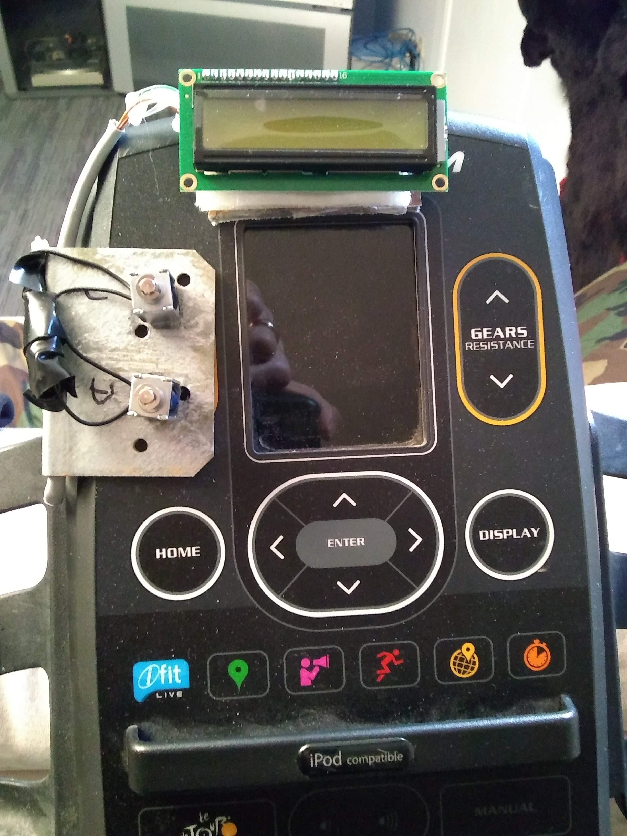
To allow better control I added an optional LCD display which I mounted over the integral TDF bike console that gives me the instantaneous grade of what the game is sending to the ESP 32 to 2 decimal places and what the ESP32 thinks the bike grade should be. If the bike console does not match the ESP32 value the appropriate solenoid should be manually activated by tapping the top of it.
Assembly:
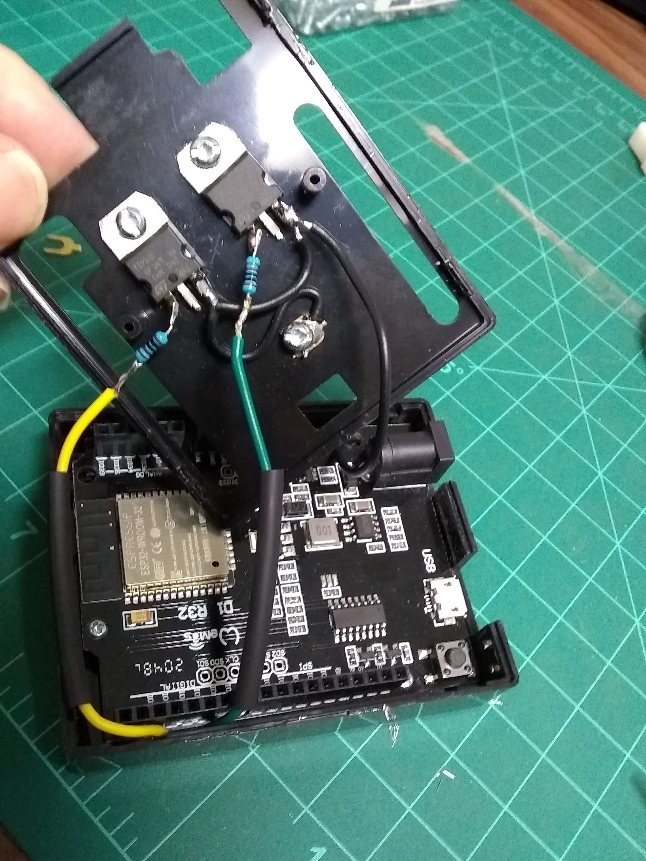
First fit the ESP32 in the enclosure. I found that the board did not quite fit and required enlarging the enclosure hole for the USB connection and barrel connector somewhat with a file. I also had to enlarge the ESP Board mounting holes a little with a drill bit (no drill) to allow alignment with the enclosure mounting posts. A couple of small mounting screws from an old watch are used to secure the board after wiring connections are completed. A couple of dabs of hot melt glue may also be used.
Prior to permanently attaching the ESP32 board to the enclosure, solder 4 inch lengths of wire to the following pins on the ESP32. I soldered the wires to the bottom of the board being careful to use the correct pins as they are only labeled from the top side.
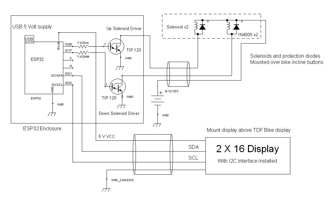
The wiring is detailed in the attached schematic. The pins used are as follows:
IO17 connects to a 1K ohm resistor that in turn is connected to the base of the "Down" TIP 120 transistor
IO26 connects to a 1K ohm resistor that in turn is connected to the base of the "Up" TIP 120 transistor.
GND connects to the emitters of both TIP 120 transistors and the negative side of the separate power supply for the solenoids.
If you wish to use the LCD display, attach wires to the pins on the ESP32 labeled as SDL and SCL. Also attach a wire to the pin labeled as 5V. Provide a wire connected to the GND connection shared with the transistors and separate solenoid power supply.
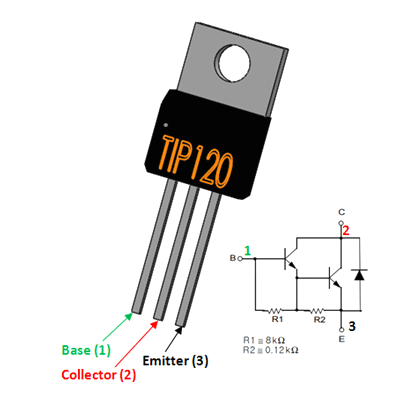
In my case I attached the transistors to the inside lid of the enclosure with #4 screws and nuts. These utilized the mounting flange of the transistors which are actually the collector terminals of the transistor (see attached picture). The mounting nuts on the exterior of the enclosure provide an easy means of attaching the wires that would feed the up and down solenoids from the transistor collector terminals.
Once all the required wires are connected to the board, attach the board to the enclosure and route the wires to the exterior of the box. Any solder joins on the wiring or transistors should be covered in electrical tape or heat shrink. Ensure when the enclosure lid is closed that no exposed wire or components touch the ESP32 board components.
Once the enclosure is closed, wrap some electrical tape around the box to prevent the transistor collector screws from making unintentional contact with anything, and also to secure the wires.
Step 3: Mount and Wire the Solenoids
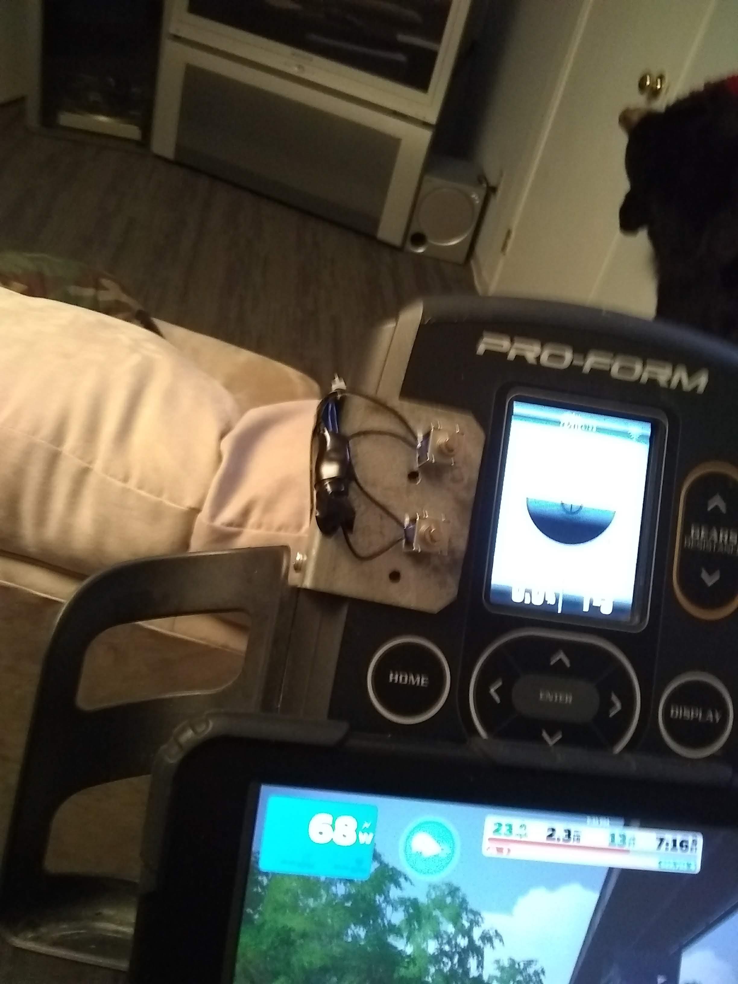
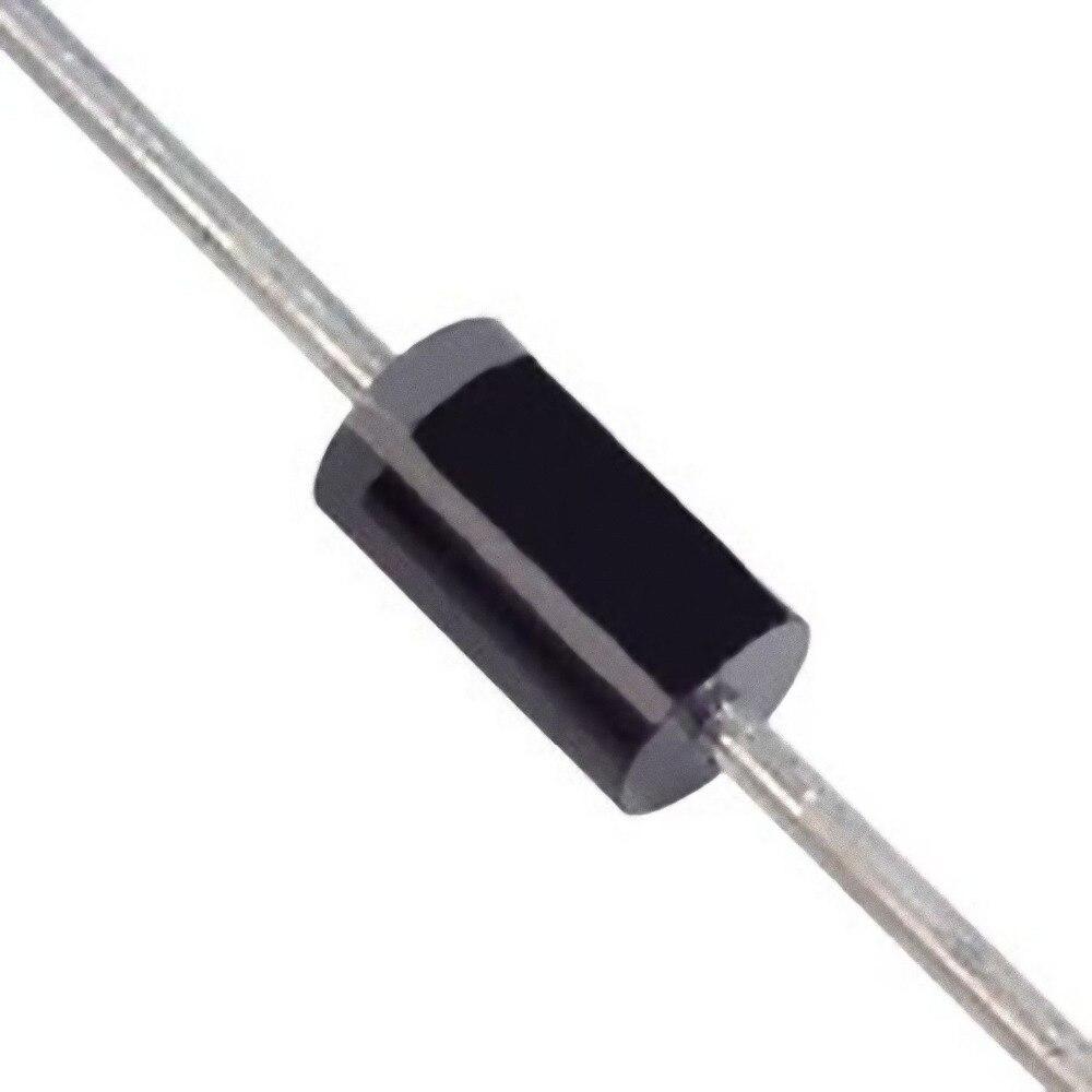
Each solenoid requires a diode to be connected across it to prevent transient voltage when the solenoid deenergizes from travelling to the transistors and control board. The solenoids each have two wires. Attach one wire to each side of the diode as shown in the schematic. This should be done as close to solenoids as possible. Solder the "bar" (cathode) side of the both diodes together, and in turn, solder this connection to the positive of the 9-12 volt power supply for the solenoids.
At this point, decide which solenoid will be "up" and which will be "down" and label accordingly. Run wire (approximately 3- 4 feet of the data cable from the parts list) from the collector of the "up" transistor mounted to the ESP32 enclosure to the "up" solenoid wire which should be connected to the "non-bar" (anode) side of its protection diode and solder together. Do the same for the "down solenoid". Wrap any exposed wiring, diodes, or solder joints in electrical tape.
I used a fencing angle bracket as a mount for the solenoids. This was something I had left over from a fencing project and seemed to fit just right (see picture). I positioned it over the up and down incline buttons on the bike and carefully marked the dead center of the buttons on the bracket. I also marked two spots on the left edge of the bracket over the seam joining the top and bottom halves of the bike console in order to mount the bracket to the console. Remove the bracket from the bike and drill holes in the bracket on the marks with an 11/64 drill bit.
On the back (bottom) of the bike console there is an access panel positioned behind the bike's display. Ensure the bike is unplugged from power and open this panel, sliding your finger along the seam where the bracket is to be positioned. Make sure that drilling holes in this area will not hit anything like circuit boards or wiring. Now reposition the bracket and drill 11/64 holes through the seam holes in the bracket and the console housing. Mount the bracket to the console with 2 x #8 x 3/4 inch bolts and nuts.
Power up the bike and place it in manual mode.
Take a solenoid and position it over the "up" hole in the bracket over the "up" button on the bike. Tap the top of solenoid plunger (the side with the spring) and ensure the plunger contacts the "up" button and the bike responds by increasing incline. Move the solenoid to the "down" hole and repeat the process to ensure the bike responds to the down actuation. You may have to adjust the bracket position, bracket bend, or even re-drill some holes to ensure the solenoid plungers will strike the bike buttons properly.
When satisfied the bracket is positioned properly, remove it from the bike. Now carefully take the solenoids and glue them to the bracket over the holes with a few drops of super glue after cleaning the bracket and solenoid plates with a scrub pad and a bit of alcohol. Be very careful in this regard as you do not want any glue running into the solenoid and fixing the plunger to the core. Clamp the solenoids in place overnight to allow the glue to cure (I used a couple of C-clamps).
When cured, remove the clamps and ensure the solenoid plungers move freely. Re-attach the bracket to the bike.
Step 4: Mounting Optional LCD Display
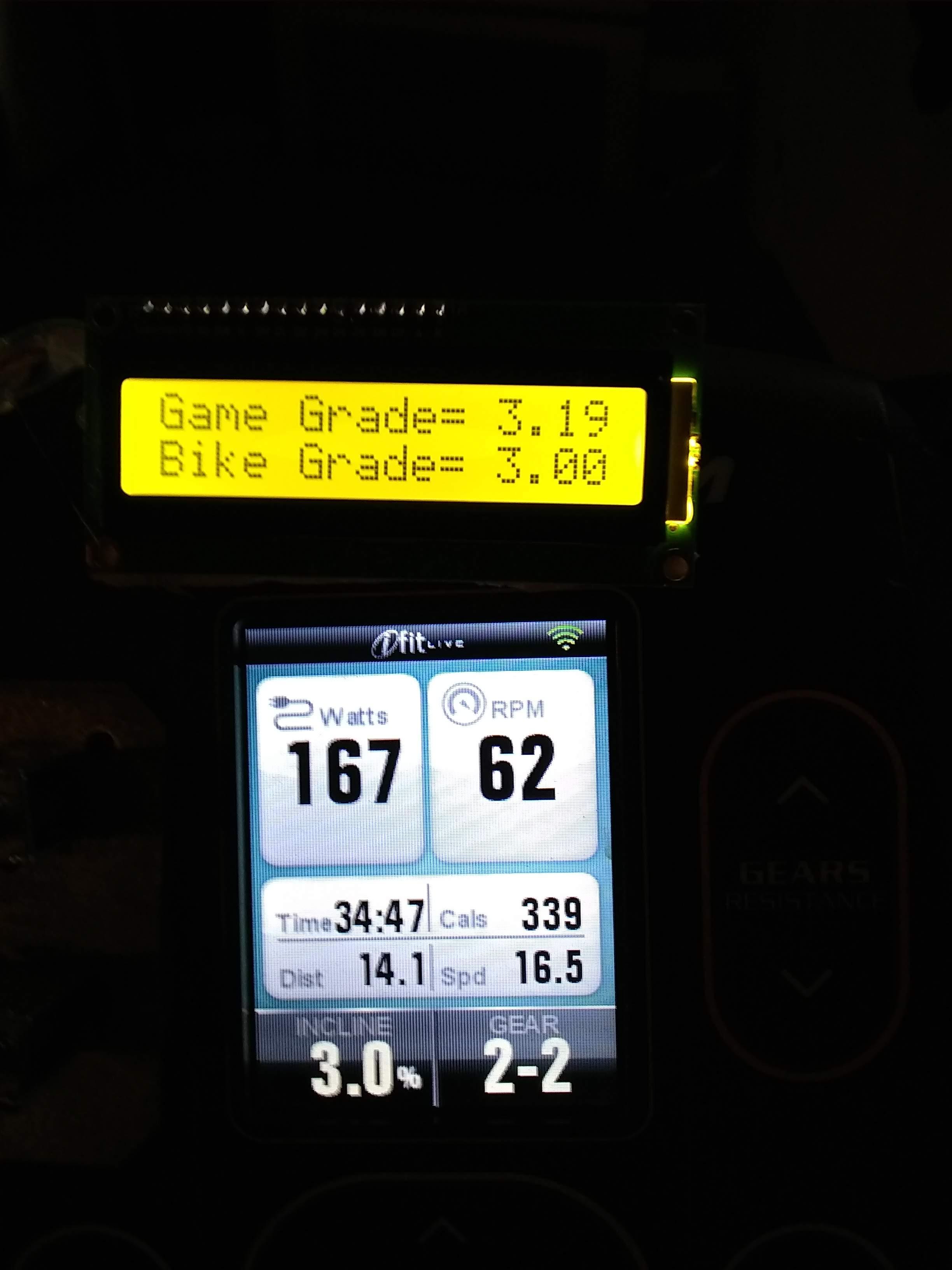
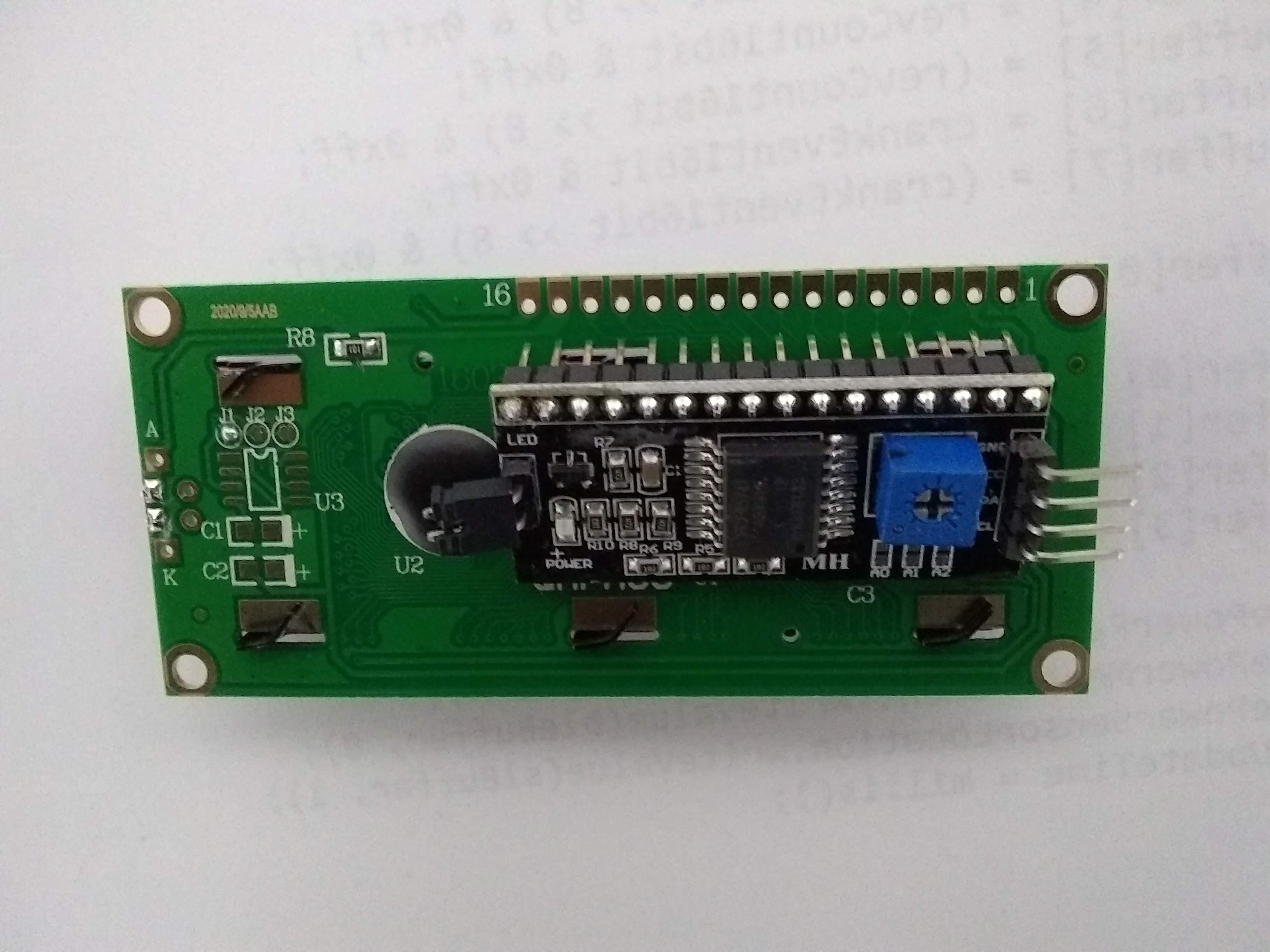
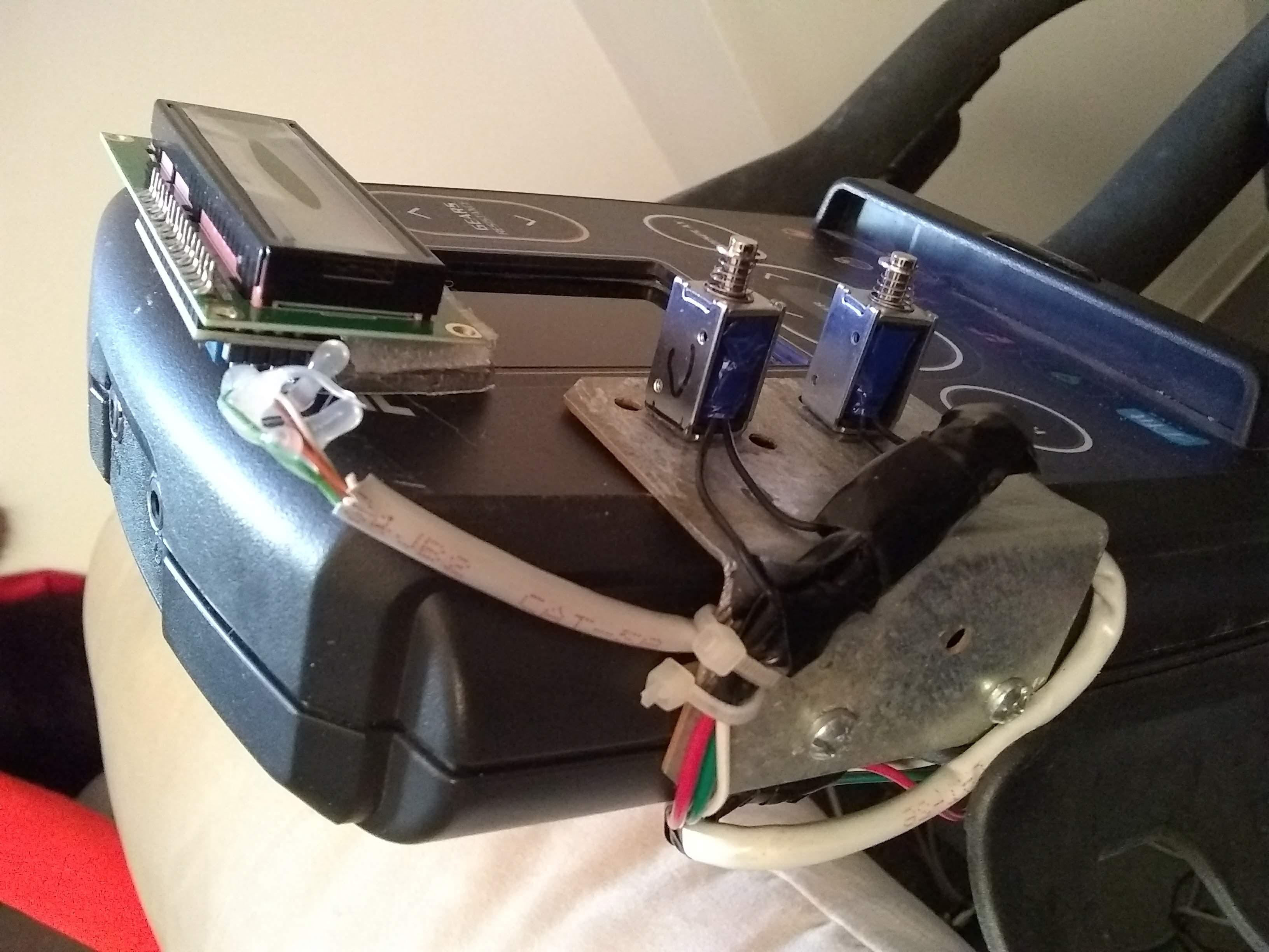
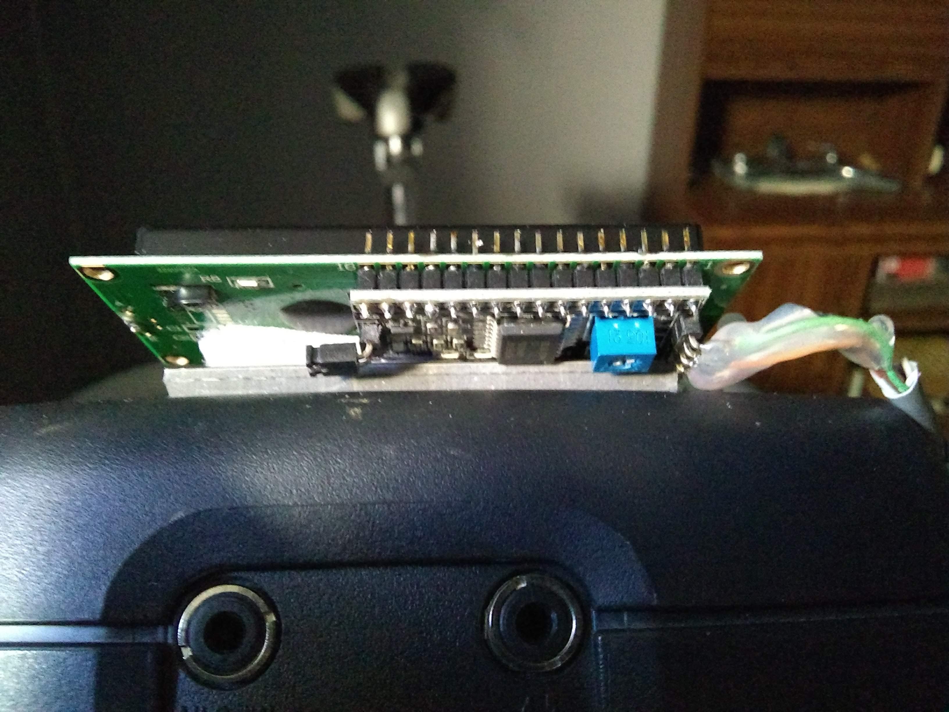
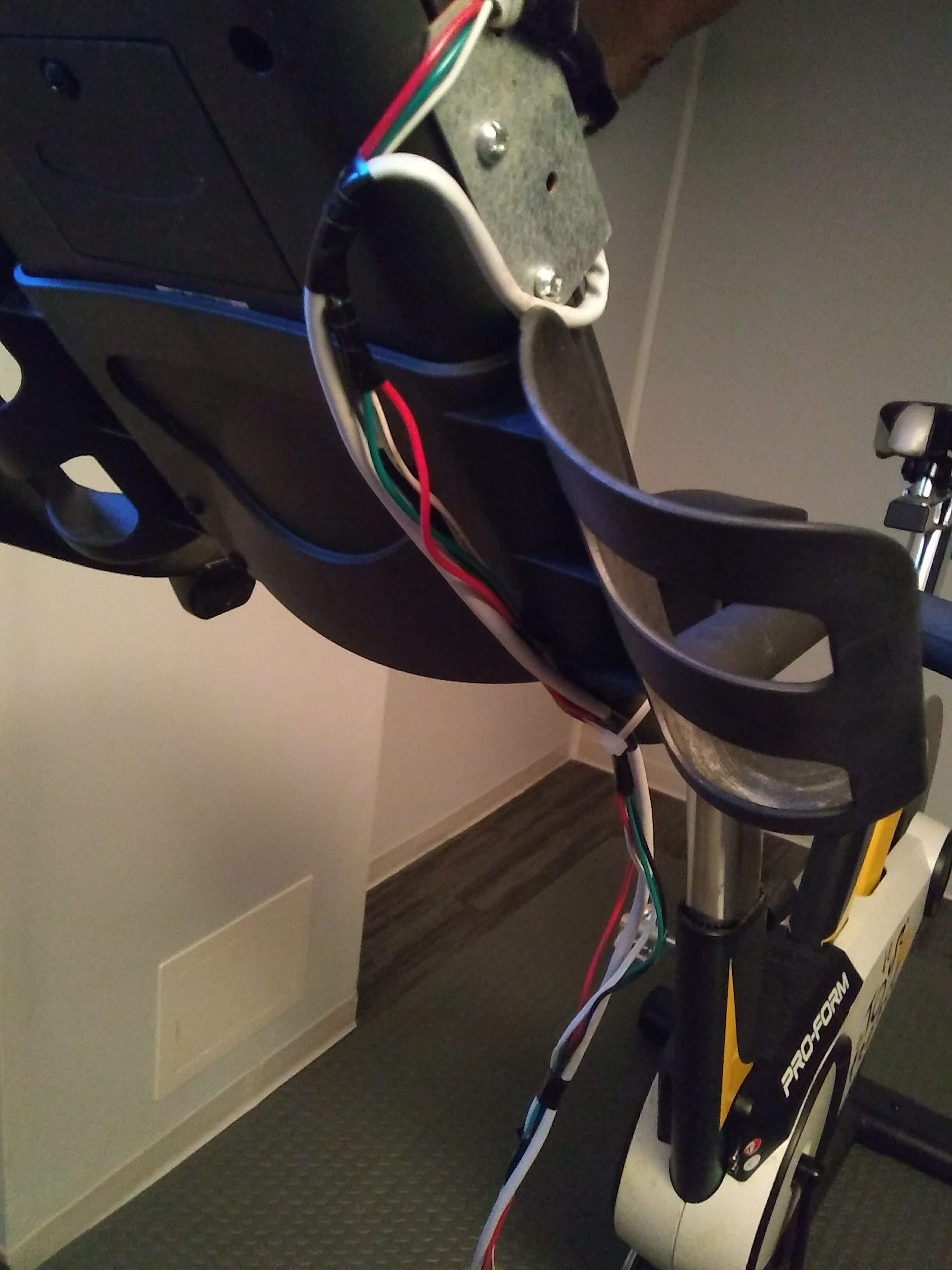
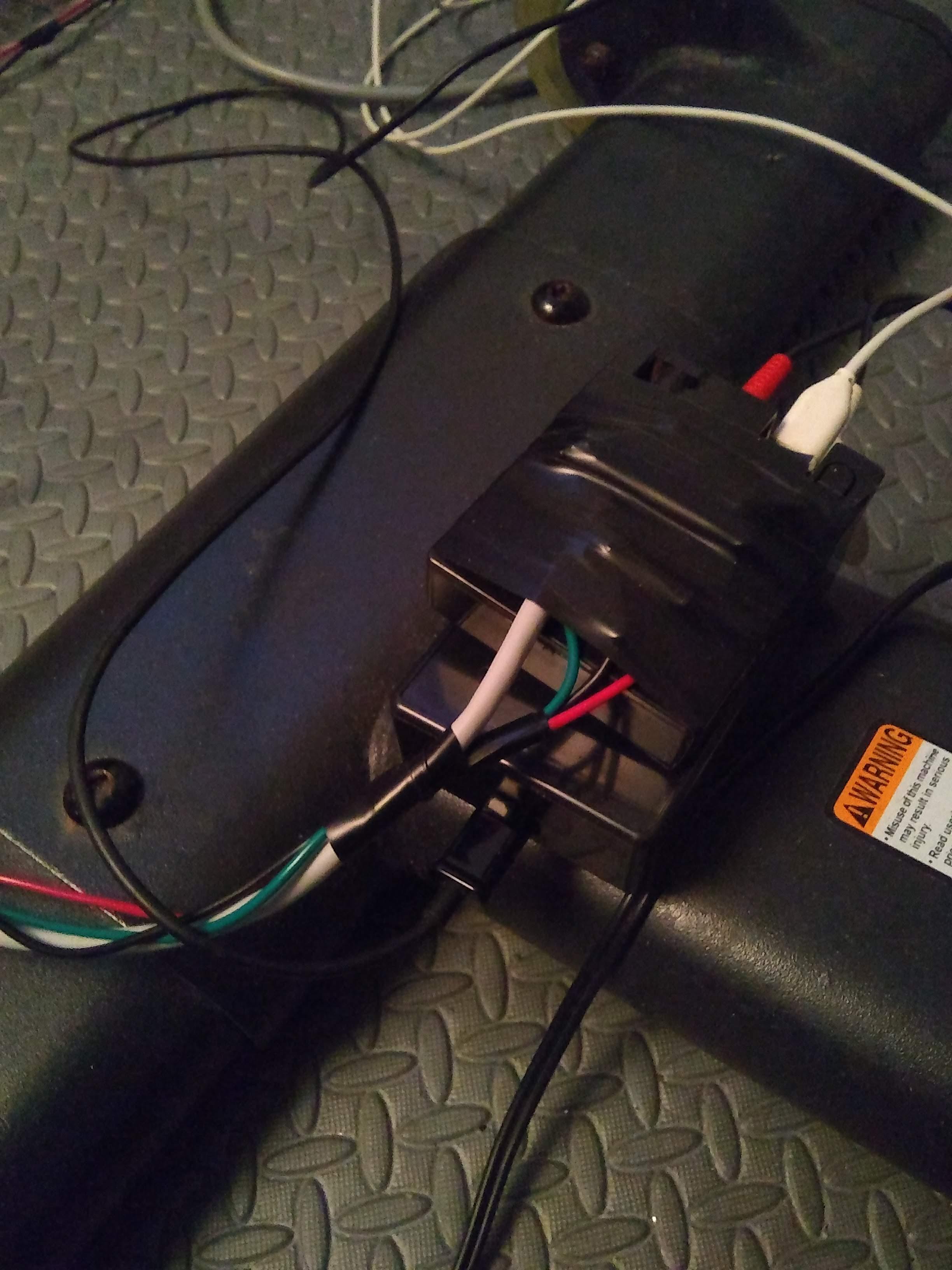
This step only applies if you wish to use the optional LCD display to provide instantaneous readout of exact game grade to two decimal places of % incline, and instantaneous readout of the % grade (in whole numbers) of what the ESP32 controller is attempting to place the bike incline at. As described earlier, if the bike's integrated display does not match the optional display of "bike grade" the top of the appropriate solenoid should be tapped to sync the bike grade to the ESP32 controller.
If you purchased the display I noted in the parts list along with the separate I2C control module, these two components will need to be soldered together. The I2C module will be inserted into the rear of the display so the pin near the LED label will insert through the hole labeled as 16 on the display board (see picture), The pins are then soldered from the front of the display (careful that solder does not bridge the pins causing a short circuit). Once the I2C module is mounted to the display, proceed to solder with a length of data cable from the edge connector of the I2C module back to the wires on the ESP32 controller as follows:
I2C GND >> ESP32 GND
I2C VCC >> ESP32 5 Volts
I2C SDA >> ESP32 SDA
I2C SCL >> ESP32 SCL
Ensure that solder does not bridge across the pins causing a short circuit. I also covered the I2C connection pins with some hot melt glue to ensure electrical isolation and add some mechanical strength to the cable.
Note that on the rear of the I2C module there is a small blue trim potentiometer that controls the contrast of the display. If the display turns on but no characters appear when the game is running this potentiometer may have to be adjusted to get the characters to display properly.
Finally attach the display to the top of the bike console with the sticky back velcro as shown in the picture. Run the cable from the display along with the solenoid cable back to the ESP32 controller securing it with nylon ties on the handlebars of the bike. Secure the cables so they will not be tangled or pulled inadvertently.
Step 5: Running the Game
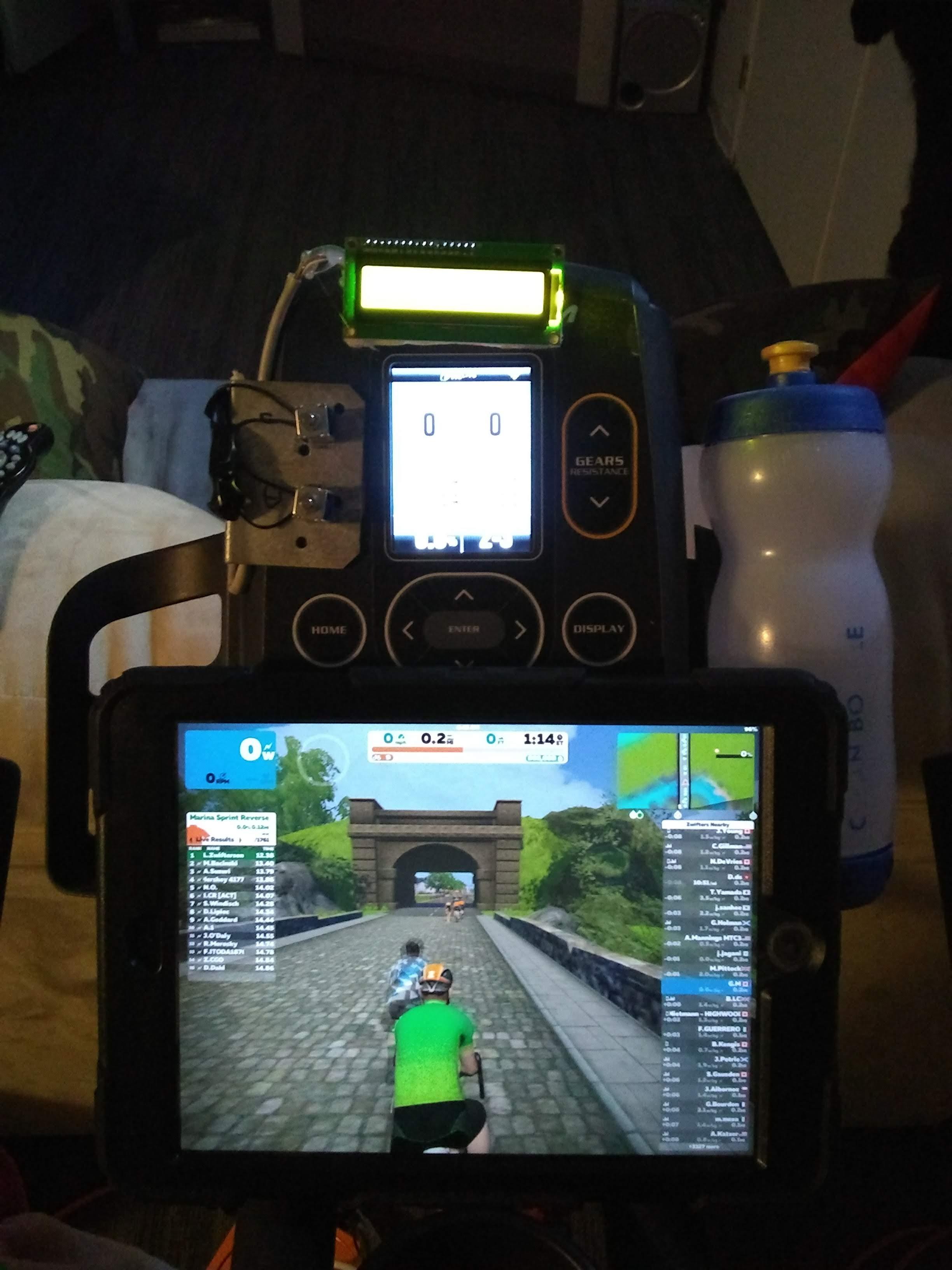
At this point you should have the following in place:
1) An Arduino Nano controller built in Part 1 of this project and connected to the TDF Bike Cadence and Power outputs and powered by a 5V USB power supply.
2) An ESP32 controller built in this Instructable, powered by a 5 volt USB powers supply.
3) A bracket with 2 solenoid actuators mounted over the TDF Bike Incline buttons with the solenoids connected to the ESP32 controller identified above.
4) A separate 9 or 12 volt power supply connected to the solenoids identified above. This power supply sharing a ground with the ESP32 controller.
5) Optionally a LCD display connected to and powered by the ESP32 controller.
6) A computer, IPAD, cell phone running a virtual cycling game such as Zwift or RGT.
To use the system:
1) Ensure the connections between the TDF bike and Nano controller (Cadence and Power) are disconnected.
2) Apply power to the TDF Bike allowing it to cycle through its power up sequence. Place the bike in manual mode and set the integrated display to show %grade and gear.
3) Apply power to the Arduino Nano, ESP32, and Solenoids. I do this by having the three power supplies connected to a switchable AC power bar.
4) Connect the cadence and power sensors from the Arduino Nano to the TDF bike.
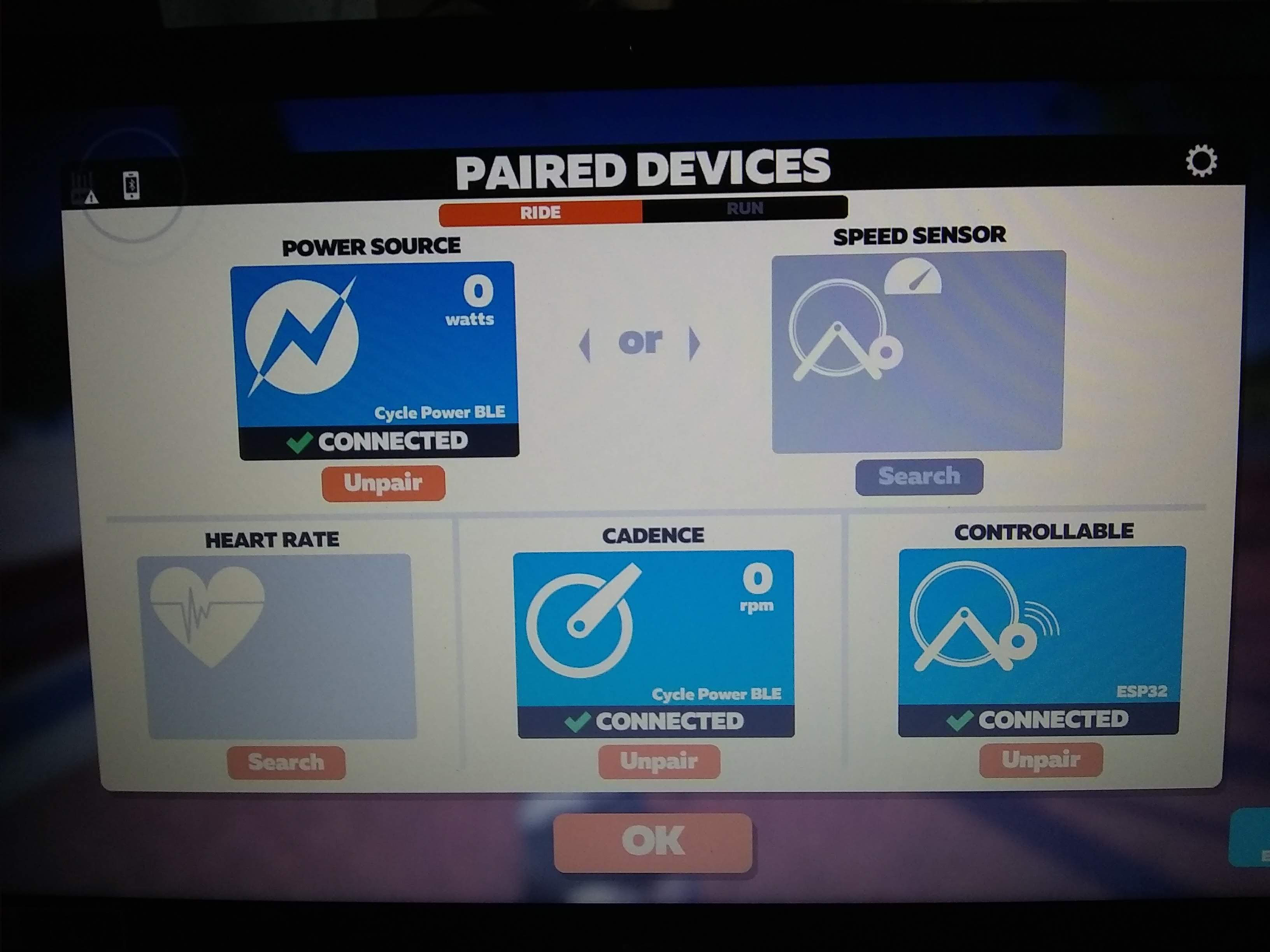
5) Start Zwift/RGT and Pair the bluetooth sensors (note- depending on device, the Arduino Nano 33 may advertise itself on bluetooth as Cycle Power BLE) see picture.
a) Power sensor should be paired with Arduino Nano 33 (Cycle Power BLE)/ Cycling power
b) Cadence sensor should be paired with Arduino Nano 33(Cycle Power BLE)/ Cycling power
c) Controllable sensor should be paired with ESP32
Note that I experienced issues using the Arduino Nano with Windows 10 over bluetooth with Zwift. If this is the case use the Android companion app on a cell phone linking with Windows 10. In the Zwift pairing screen use the option to connect with companion app and pair the Nano and ESP32. You may have to pair the ESP32 first as the cycling power sensor in order for it to pair as the controllable sensor. Once this is done, unpair it as the power sensor, then pair the Nano 33(Cycle Power BLE). I experienced no such problems using Zwift with an IPAD, that is both controllers paired easily without the use of the companion app.
6) Select the course and ride!