Connected Meteorological Station
by Clarissek12 in Circuits > Arduino
242 Views, 3 Favorites, 0 Comments
Connected Meteorological Station
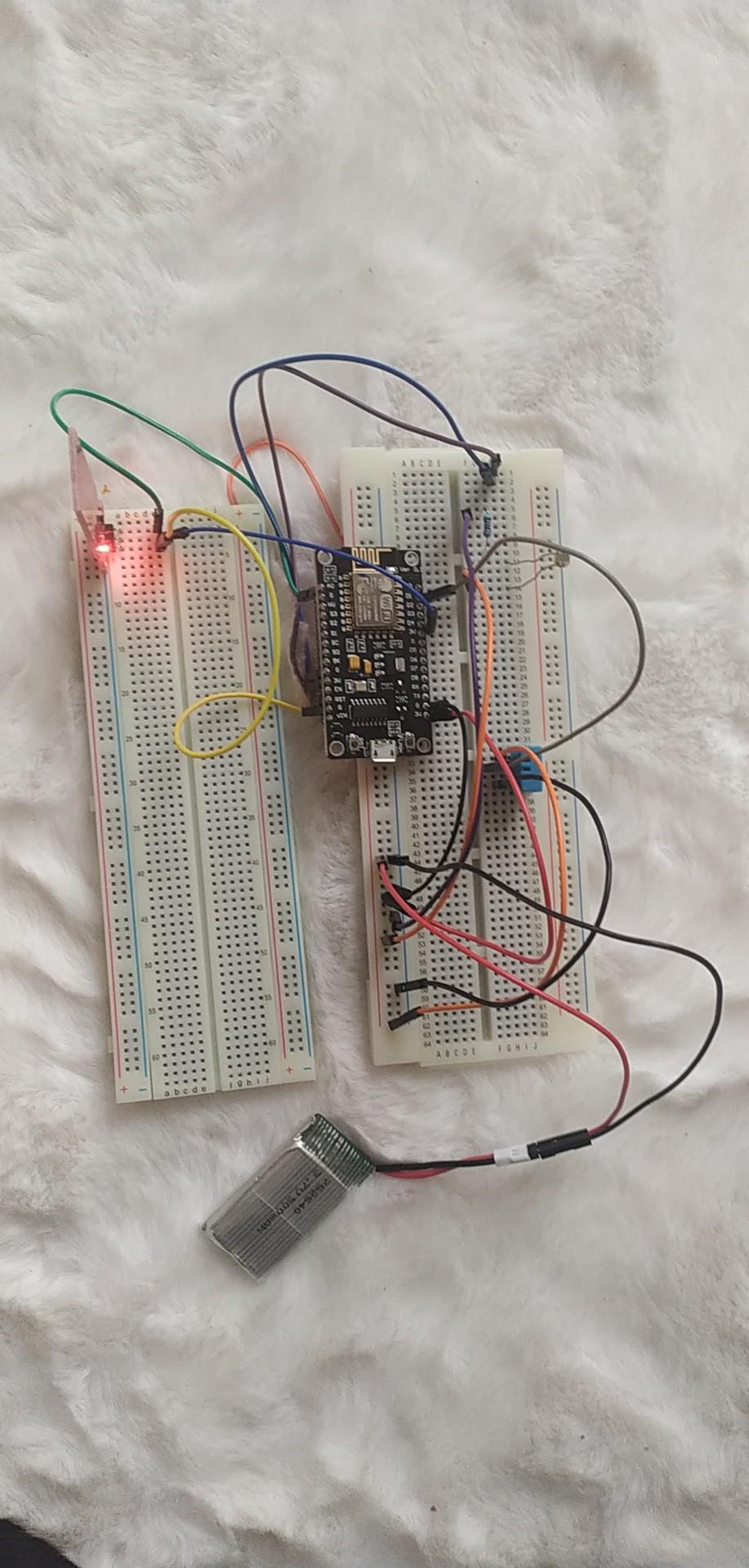
We decided to create a meteorological station made of DHT11 sensor (humidity and temperature), a luminosity sensor and a water level sensor (rain).
We want our station to be connected and to display its info online using Scaleway.
We used an ESP8266 and we supply it with a battery. You can see the results on Node-Red with an IP address.
We also use DeepSleep protocol to economize the battery.
Supplies
Analogic tools:
- ESP8266
- DHT11 sensor
- Luminosity sensor
- Water level sensor SE045
- Resistor of 2Kohm
- Cables
- Battery of 3.7V
Digital tools:
- Scaleway
- MQTT Explorer
- Node-red
- Arduino
Step 1 : Scaleway

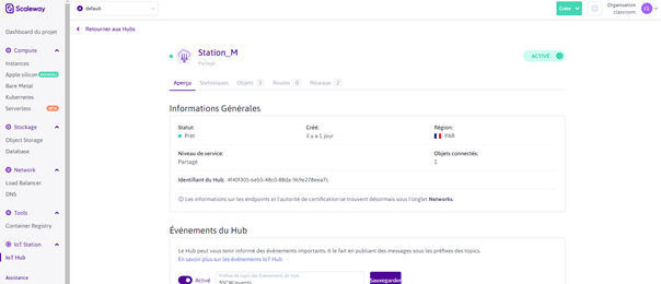
First, you will need a Scaleway account. If it’s not the case, begin by creating one.
You are now in front of the Scaleway Console.
Now we want to create an IoT Hub, go to the IoT Hub tab:
Name your Hub, select the Free Shared option and validate. Now you can see your Hub in the IoT Hub tab.
Select your Hub, now you should see this screen appear:
Go to the Devices tab, click on add Devices, name it and select the Allow insecure connection before validating.
Your device should now appear in the Devices tab of your Hub.
Now repeat the process to create two other devices, name them with the same name as the first one but add mqtt-explorer to one, and nodered to the other.
You have now 3 devices in your Devices tab.
Step 2 : MQTT Explorer
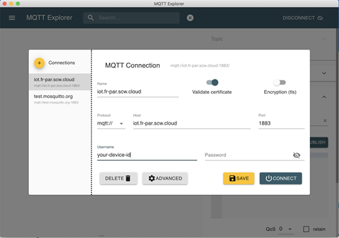
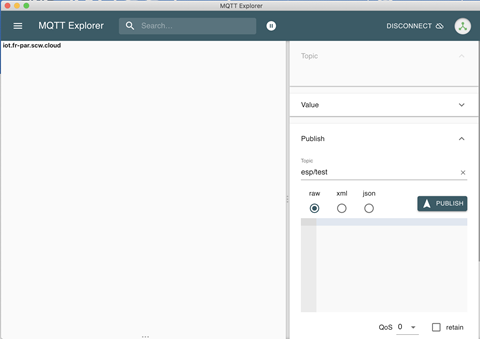
Now, open your MQTT Explorer application, if you don’t have it you can download it here: http://mqtt-explorer.com/
Fill your MQTT Explorer as shown here:
Fill the Username field with the id of your device name with mqtt-explorer. To find it, open your device, the id will be displayed on the information screen.
Once it is done, click on Connect. This screen should appear:
Step 3 : DHT11 Sensor
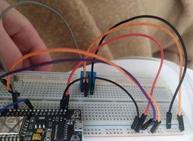
Now, let's begin with the hardware side !!
- Take your DHT11 and your ESP8266.
- Put your DHT11 in your breadbord.
- Take your first cable and put it in the first branch of your DHT11. Connect it to 3V (Such as the orange cable on the picture)
- Put your second cable in the second branch of your DHT11 and connect it to D1 (= pin 5). (Grey cable).
- Now put your third cable to your last branch and connect it to the ground.
You already connected your DHT11 sensor ! Congrats !
Step 4 : Luminosity Sensor
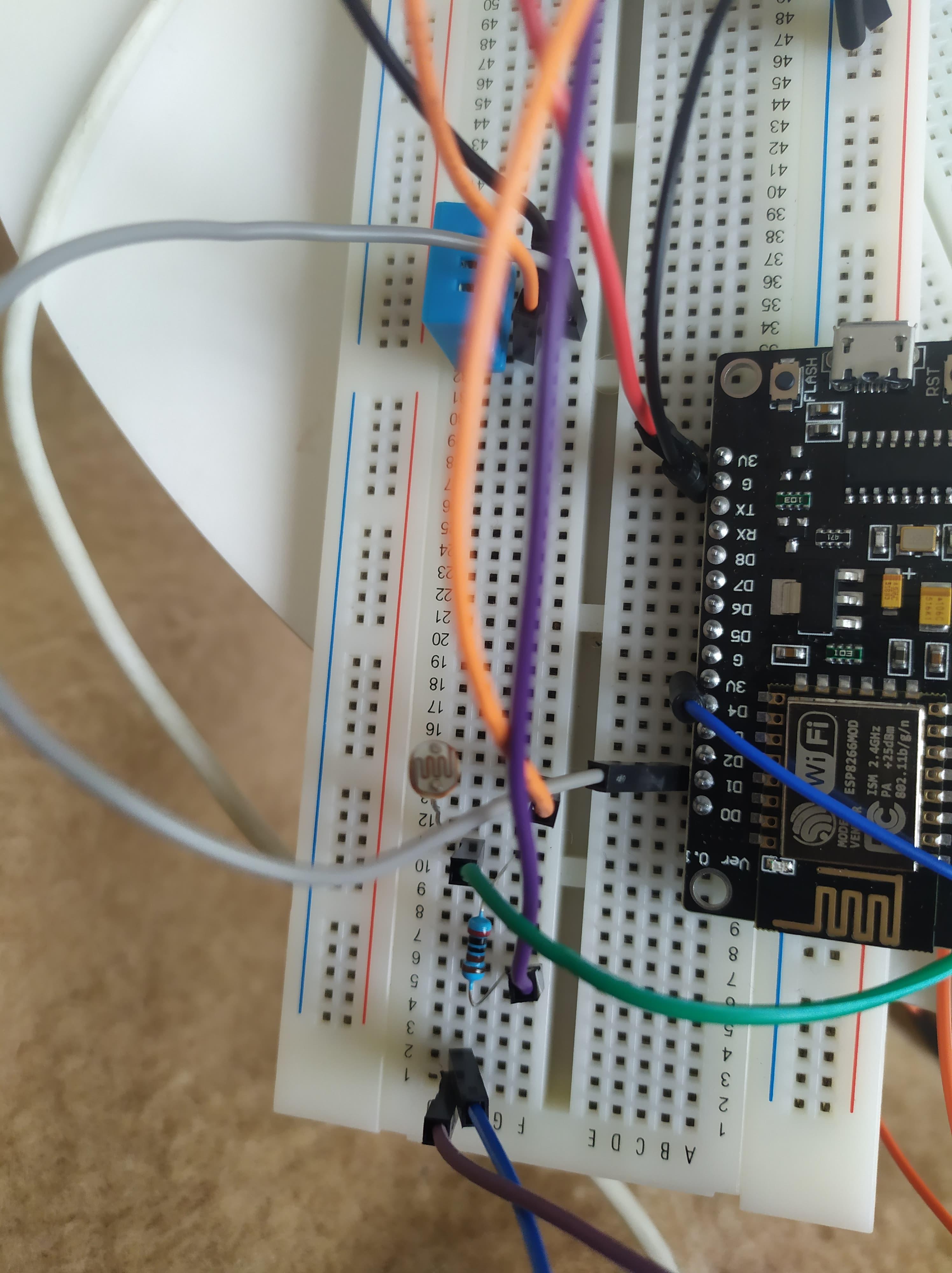
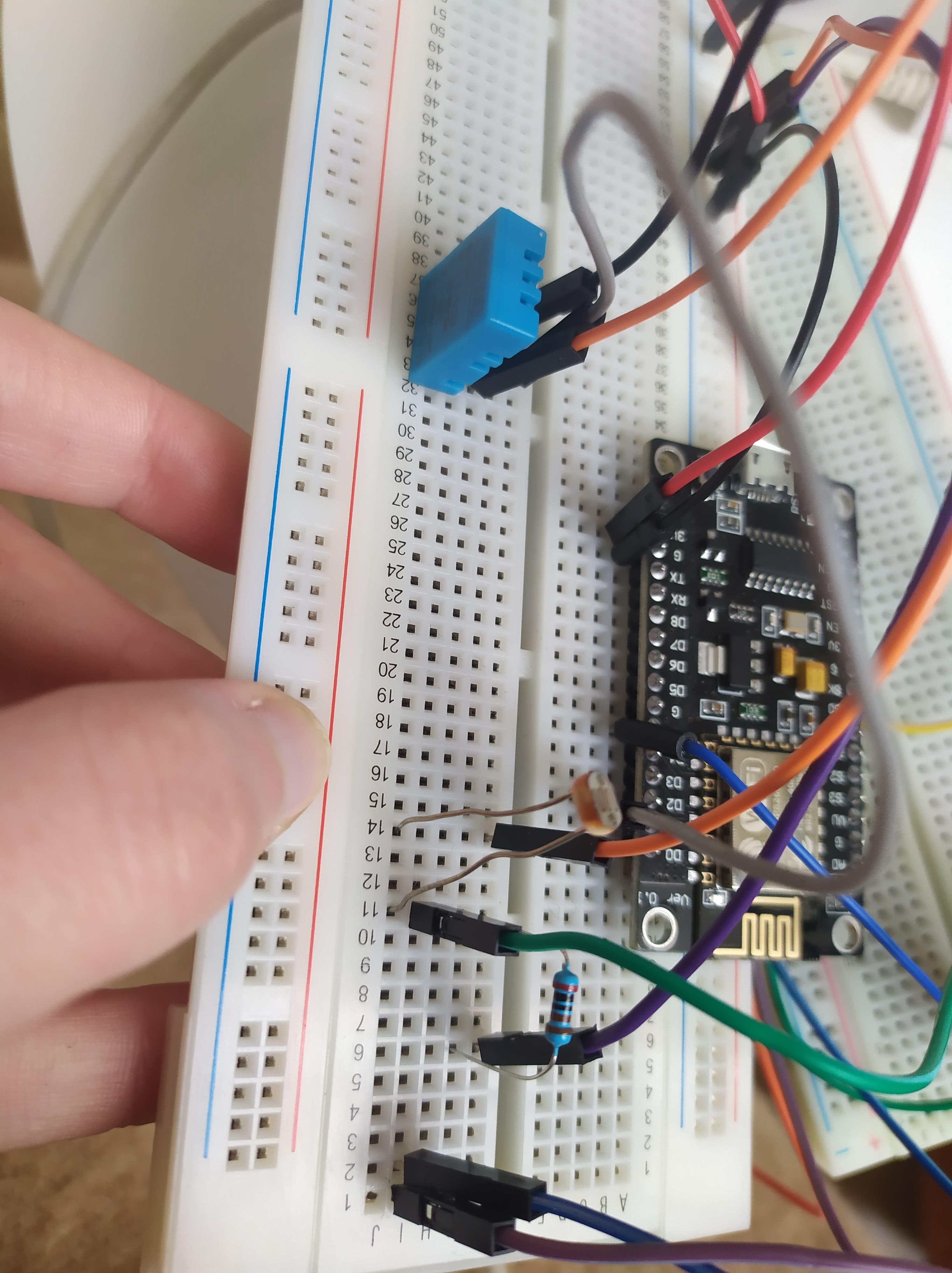
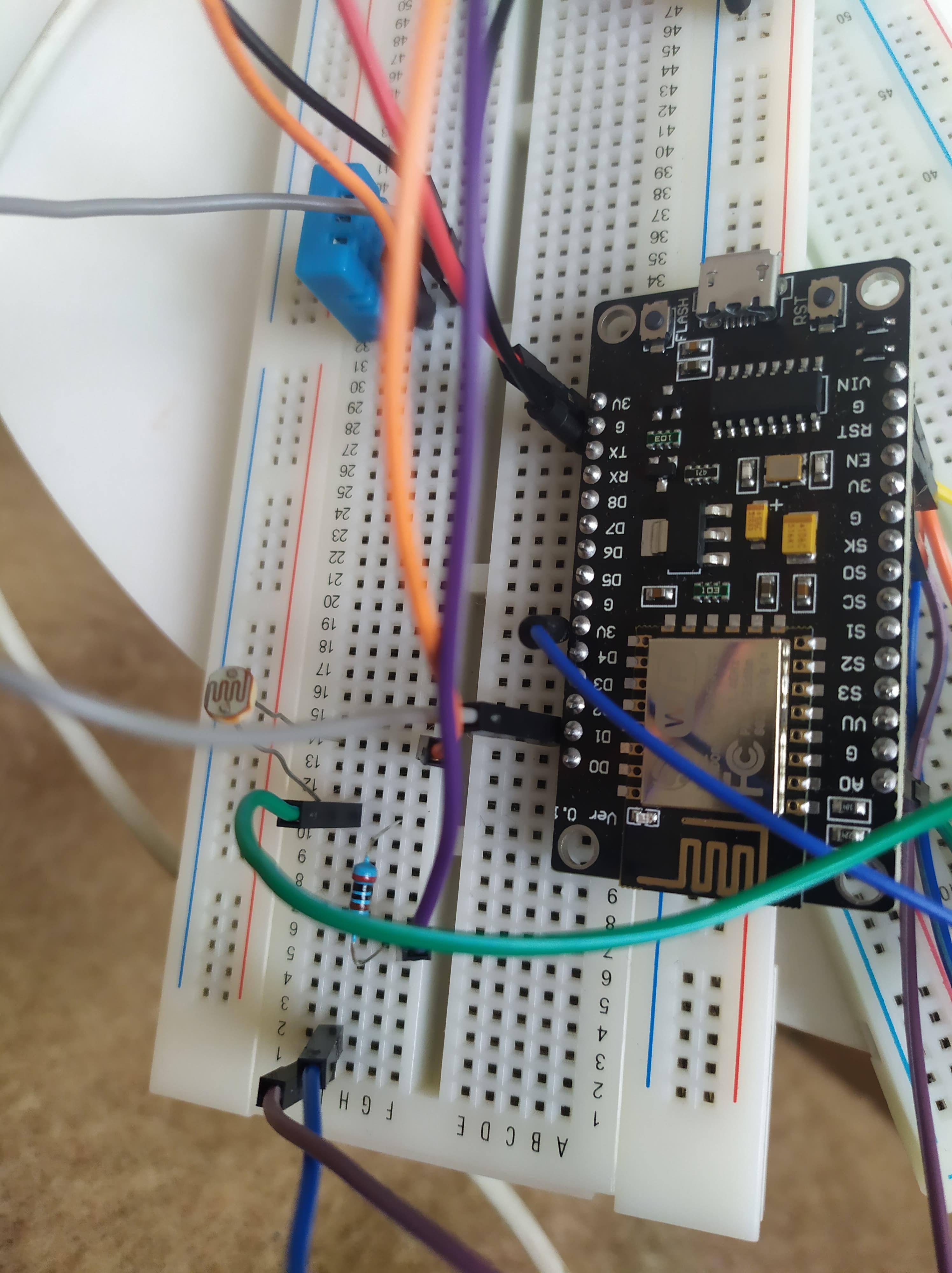
Welcome at our 4th step !
Here, you will learn how to connect your Luminosity sensor.
First, take an 2KΩ resistor and put it to the left side of your sensor. One branch of the resistor and one branch of the light sensor have to be on the same column.
Now, the instructions about the cables :
- Put your fisrt cable in the same column than the one were both branch of the resistor and the sensor communicate. This cable goes to the analogic port A0 (green).
- Put a second cable at the other branch of the resistor and connect it to the esp's ground (violet).
- Third one links the other branch of the sensor to 3V (orange).
Step 5 : Arduino Part
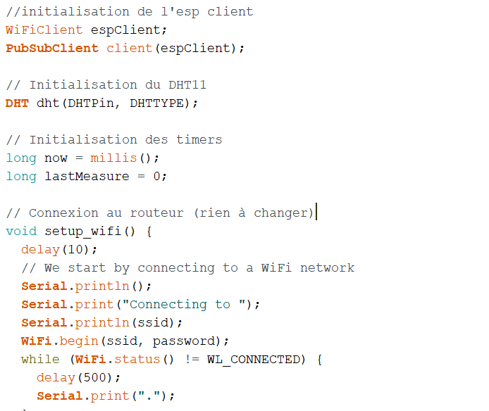
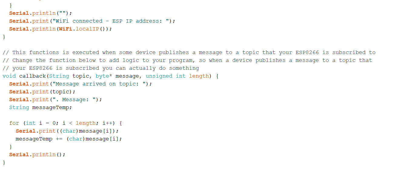
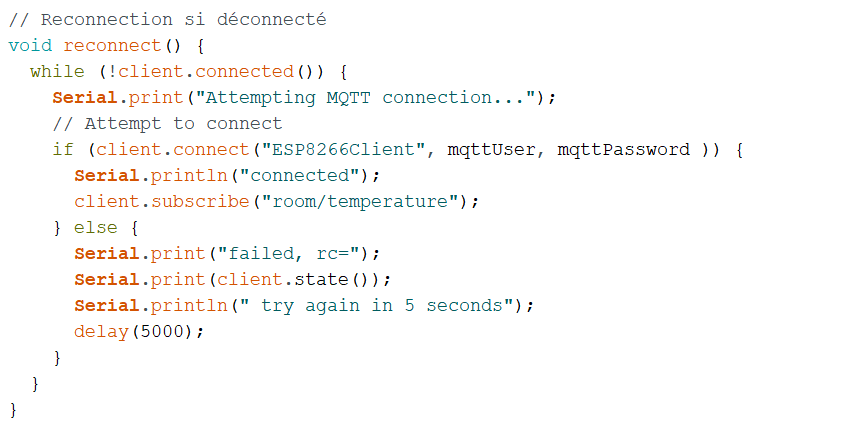
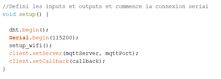
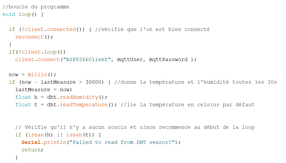
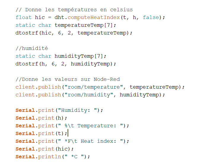
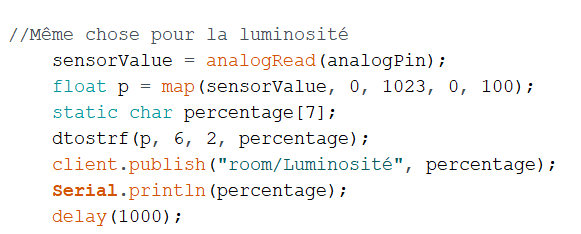

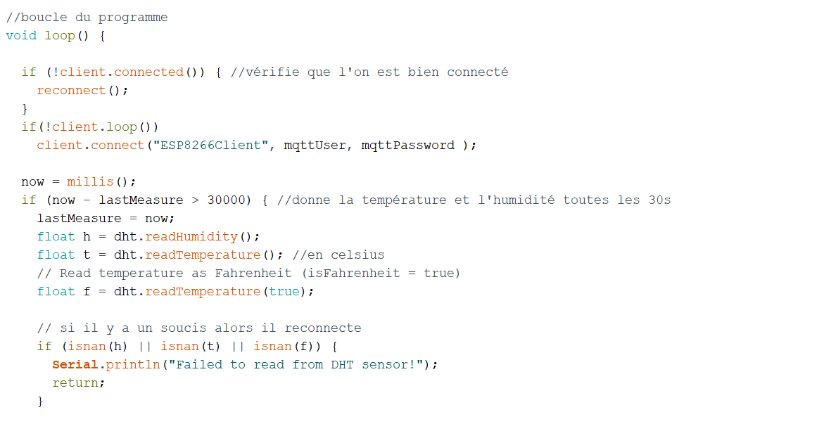
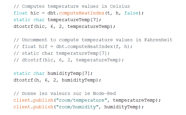
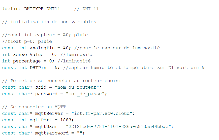
#include //bibliothèques pour le wifi #include #include "DHT.h" //bibliothèque du capteur
#define DHTTYPE DHT11 // DHT 11
// initialization of variables
const int analogPin = A0; //Luminosity sensor int sensorValue = 0; //luminosity sensor int percentage = 0; //luminosity const int DHTPin = 5; //capteur humidité et température sur D1 soit pin 5
// Permet de se connecter au routeur choisi const char* ssid = "name_of_your_wifi"; const char* password = "password";
// To connect to MQTT const char* mqttServer = "your_host"; const int mqttPort = 1883; const char* mqttUser = "device-id"; const char* mqttPassword = "";
//Initialization esp_client WiFiClient espClient; PubSubClient client(espClient);
//Initialization of DHT11 DHT dht(DHTPin, DHTTYPE);
// Initialization of timers long now = millis(); long lastMeasure = 0;
// Connexion to your router void setup_wifi() { delay(10); // We start by connecting to a WiFi network Serial.println(); Serial.print("Connecting to "); Serial.println(ssid); WiFi.begin(ssid, password); while (WiFi.status() != WL_CONNECTED) { delay(500); Serial.print("."); } Serial.println(""); Serial.print("WiFi connected - ESP IP address: "); Serial.println(WiFi.localIP()); }
// This functions is executed when some device publishes a message to a topic that your ESP8266 is subscribed to // Change the function below to add logic to your program, so when a device publishes a message to a topic that // your ESP8266 is subscribed you can actually do something void callback(String topic, byte* message, unsigned int length) { Serial.print("Message arrived on topic: "); Serial.print(topic); Serial.print(". Message: "); String messageTemp; for (int i = 0; i < length; i++) { Serial.print((char)message[i]); messageTemp += (char)message[i]; } Serial.println(); }
// Reconnection if disconnect void reconnect() { while (!client.connected()) { Serial.print("Attempting MQTT connection..."); // Attempt to connect if (client.connect("ESP8266Client", mqttUser, mqttPassword )) { Serial.println("connected"); client.subscribe("room/temperature"); } else { Serial.print("failed, rc="); Serial.print(client.state()); Serial.println(" try again in 5 seconds"); delay(5000); } } }
//Definie inputs and outputs + serial begin void setup() {
//pinMode(capteur, INPUT); pluie dht.begin(); Serial.begin(115200); setup_wifi(); client.setServer(mqttServer, mqttPort); client.setCallback(callback); }
//loop void loop() {
if (!client.connected()) { //vérifie que l'on est bien connecté reconnect(); } if(!client.loop()) client.connect("ESP8266Client", mqttUser, mqttPassword );
now = millis(); if (now - lastMeasure > 30000) { //donne la température et l'humidité toutes les 30s lastMeasure = now; float h = dht.readHumidity(); float t = dht.readTemperature(); //en celsius // Read temperature as Fahrenheit (isFahrenheit = true) float f = dht.readTemperature(true);
// if problem then it restarts if (isnan(h) || isnan(t) || isnan(f)) { Serial.println("Failed to read from DHT sensor!"); return; }
// Computes temperature values in Celsius float hic = dht.computeHeatIndex(t, h, false); static char temperatureTemp[7]; dtostrf(hic, 6, 2, temperatureTemp); // Uncomment to compute temperature values in Fahrenheit // float hif = dht.computeHeatIndex(f, h); // static char temperatureTemp[7]; // dtostrf(hic, 6, 2, temperatureTemp); static char humidityTemp[7]; dtostrf(h, 6, 2, humidityTemp);
// Gives value on node-red client.publish("room/temperature", temperatureTemp); client.publish("room/humidity", humidityTemp); Serial.print("Humidity: "); Serial.print(h); Serial.print(" %\t Temperature: "); Serial.print(t); Serial.print(" *C "); Serial.print(f); Serial.print(" *F\t Heat index: "); Serial.print(hic); Serial.println(" *C "); // Serial.print(hif); // Serial.println(" *F");
//Same for luminosity sensorValue = analogRead(analogPin); float p = map(sensorValue, 0, 1023, 0, 100); static char percentage[7]; dtostrf(p, 6, 2, percentage); client.publish("room/Luminosité", percentage); Serial.println(percentage); delay(1000);
}
}
Step 6 : DeepSleep

If you use the DeepSleep protocol to
consume less energy, you need to activate it on your board.
To do so, use a wire to connect your D0 pin with your RST pin.
This connection may cause some problems with the uploading of your code on the board, it is advised to unplug this wire during the uploading and plug it back once it is complete.
Sept 7 : Battery

Now let's add a battery ! Our station will have an autonomy thanks to it !
WARNING : Take a voltage battery below 9V except if you want to exterminate your circuit !
We took an 3.7V battery.
To connect it, nothing easier : connect it to the ground and to Vin respectively.
Step 8 : Water Level Sensor (rain)
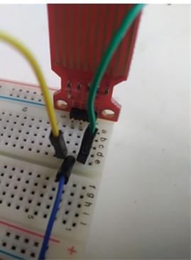
WARNING : The water level sensor use the 10 port such as the luminosity one. As we only have one analog port we can’t use both at the same time. But you have more than one analogic port, then feel free to use both !!
Steps to connect it :
- Do you see the green cable ? Connect it to A0.
- The blue cable in the middle has to goes to 3V.
- Finally, the yellow one has to goes to the ground.
Wasn't it easy ?? You did it !!
Step 9 : Water Level Sensor Arduino Code
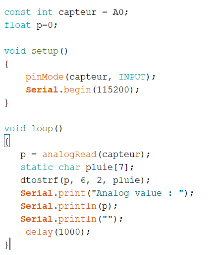
You will find out the code in the image. It's the same operation than for the luminosity sensor.
Congratulations !!!! You finished the code and the hardware part !!!!
Now let's see how to get your datas on Node-Red ! See you at Step 10 !
Step 10 : Flow Programming
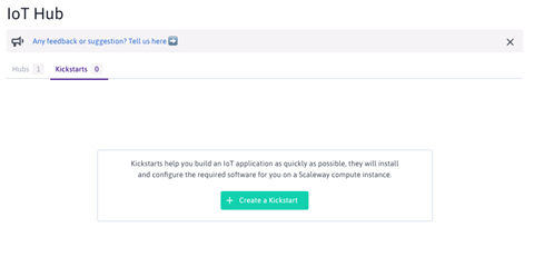
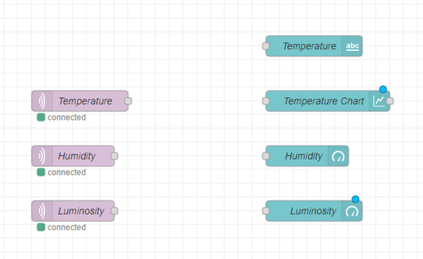


Now go back to Scaleway, go to the IoT Hub tab and then to the Kickstarts tab.
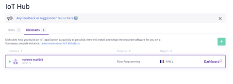
Create a kickstart, choose the Flow Programming option. In the Choose a Hub and Device pannel, select your Hub, then select the device you named with nodered.
Name your kickstart and validate.
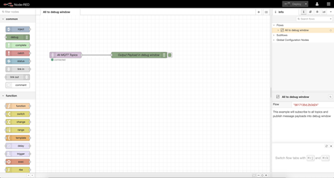
Now your kickstart should appear in your Kickstarts tab. Next, click on Dashboard and log in.
Once it is done you should see this:
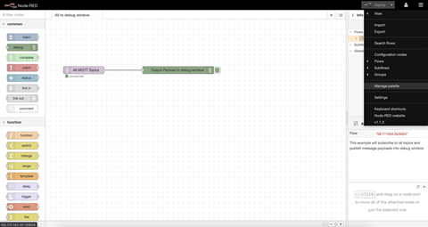
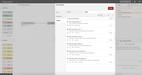
Now we will add new types of nodes, to do so, click on the menu at the top right and select Manage palette.
A list of nodes will appear, search for node-red-dashboard and install it.
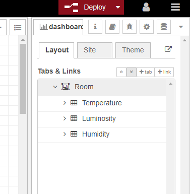
Now go in the Dashboard tab then Layout tab and create a new tab and inside this tab, add 3 groups, and name them as shown here:
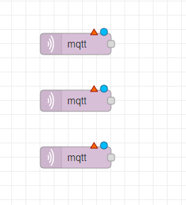
Now create a new flow and add mqtt in 3 nodes.
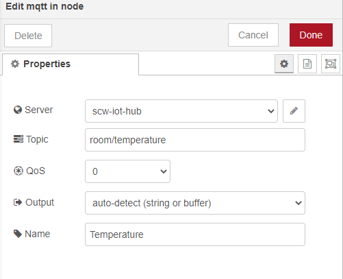
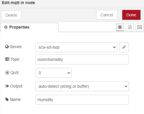
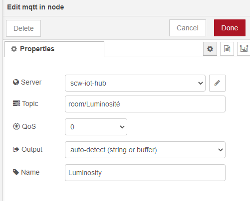
Now you will double-click on them and edit them as shown here:
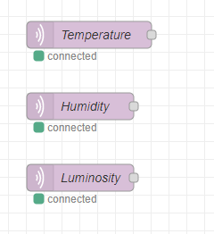
Your 3 nodes should now look like this:
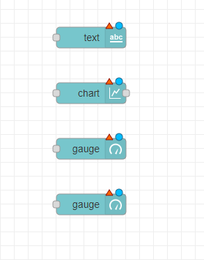
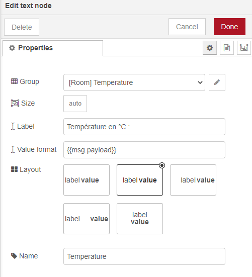
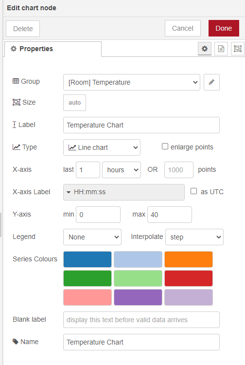
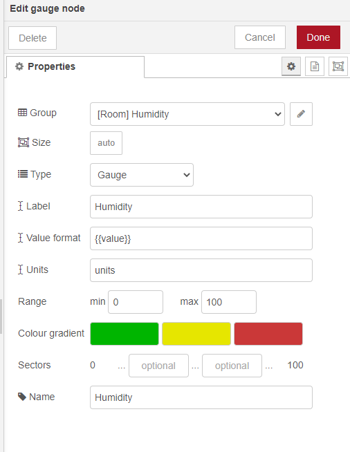
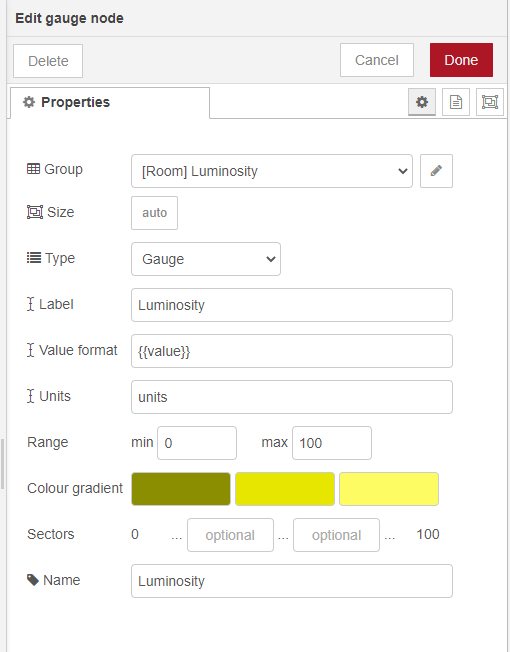
Now add a text node, a chart node and 2 gauge node.
And Edit them as shown here:
Your nodes should now look like this:
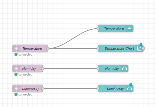
Now, link them like this:
Now, click on Deploy, in the top right corner.
Now, open a new tab with the URL:“http://your-ip:1880/ui/"
Instead of “your-ip”, type the ip address you can read in the URL of your Node-RED page.