Connect Your LS20031 GPS Receiver to Google Earth Via PC
by techbitar in Circuits > Gadgets
53570 Views, 183 Favorites, 0 Comments
Connect Your LS20031 GPS Receiver to Google Earth Via PC
UPDATES
Oct 31: Corrected pin numbers for how to wire the SN74AHC125 IC.
INTRODUCTION
In this guide I will hook-up the LS20031 GPS receiver to a PC (most likely a laptop) to interface it to Google Earth. This is a 3-part process:
LS20031 GPS RECEIVER SPECIFICATIONS
The LS20031 is a bread and butter GPS receiver. It's very simple to operate like most serial GPS receivers. It's a decent receiver for the money (appx. $50). This receiver is made by LOCOSYS Technology.
HARDWARE PARTS LIST
It's possible to use a 3.3V FTDI interface to wire the LS20031 directly to the PC without the 5V to 3.3V level-shifting, but I am planning to use this prototype for my GPS logger which is controlled by a 5V Arduino Uno. Also, most of the FTDI interfaces in circulation in my geek group (PIN13 Protospace) were purchased from Ebay and they tend to be 5V only.
I tried using resistors as voltage dividers to shift from 5V to 3.3V but the circuit was unstable, especially when an SD card was part of the circuit So I opted to use a 3.3V regulator and a quad bus buffer to drop the FTDI's 5V power pin and the TX signal from 5V to 3.3V. The performance of the final prototype is stable.
CONTACT
Hazim Bitar (techbitar)
techbitar at gmail dot com
VIDEO DEMO
This is a short video to help visualize the process of exporting the NMEA coordinates from MiniGPS to a log file. Also, the video shows how to connect Google Earth to the GPS receiver to receive NMEA coordinates and other data in realtime as well as how to import the NMEA log file generated by MiniGPS into Google Earth.
Oct 31: Corrected pin numbers for how to wire the SN74AHC125 IC.
INTRODUCTION
In this guide I will hook-up the LS20031 GPS receiver to a PC (most likely a laptop) to interface it to Google Earth. This is a 3-part process:
- Wire the LS20031 GPS receiver to the FTDI serial-USB interface.
- Configure the LS20031 GPS receiver baud rate and other settings using the MiniGPS 1.4 utility.
- Connect the LS20031 GPS receiver either in real-time or batch-mode (import NMEA log file) to Google Earth.
LS20031 GPS RECEIVER SPECIFICATIONS
The LS20031 is a bread and butter GPS receiver. It's very simple to operate like most serial GPS receivers. It's a decent receiver for the money (appx. $50). This receiver is made by LOCOSYS Technology.
- Model: LS20031
- Chip: MediaTek MT3329
- Voltage: 3.3V
- Frequency: L1 1575.42MHz, C/A code
- Channels: Support 66 channels (22 Tracking, 66 Acquisition)
- Update rate: 1Hz default, up to 10Hz
- Hot start: (Open Sky) < 2 seconds (typical)
- Acquisition Time: Cold Start (Open Sky) 35 second (typical)
- Autonomous 3m (2D RMS)
- Position Accuracy: SBAS 2.5m (depends on accuracy of correction data)
- Datum: WGS-84 (default)
- Max. Operating Altitude: < 18 Km
- Max. Operating Velocity: < 515 m/s
HARDWARE PARTS LIST
It's possible to use a 3.3V FTDI interface to wire the LS20031 directly to the PC without the 5V to 3.3V level-shifting, but I am planning to use this prototype for my GPS logger which is controlled by a 5V Arduino Uno. Also, most of the FTDI interfaces in circulation in my geek group (PIN13 Protospace) were purchased from Ebay and they tend to be 5V only.
I tried using resistors as voltage dividers to shift from 5V to 3.3V but the circuit was unstable, especially when an SD card was part of the circuit So I opted to use a 3.3V regulator and a quad bus buffer to drop the FTDI's 5V power pin and the TX signal from 5V to 3.3V. The performance of the final prototype is stable.
- LS20031 GPS Receiver: $50 (Ebay, Pololu, SparkFun, Adafruit)
- Basic FTDI (5V) Serial over USB: $7 (Ebay)
- SN74AHC125 Quad Buffer used as 5V to 3.3V level shifter/converter: $0.5 You can user the popular CD4050 if you prefer. They are not pin compatible but plenty of wiring examples on net. (Mouser).
- LM1117T-3.3V Regulator TO-220: $0.5 (Futurlec, Ebay)
- Electrolytic capacitors 10uf X 2: $0.5
- Breadboard
- Right-angle male header 2.54mm/0.1in. Only 5-pins are needed to be soldered to the GPS receiver so we can plug it into the breadboard.: $0.5 (Ebay)
- Jumper wires
- MiniGPS - To configure and debug the GPS receiver
- Google Earth - To map the data tracked by the GPS receiver
- TeraTerm - You can use this simple terminal software to also receive and send data to/from the GPS receiver. In this guide I will use it as a detection tool to find out which COM port the FTDI adapter is connected to.
CONTACT
Hazim Bitar (techbitar)
techbitar at gmail dot com
VIDEO DEMO
This is a short video to help visualize the process of exporting the NMEA coordinates from MiniGPS to a log file. Also, the video shows how to connect Google Earth to the GPS receiver to receive NMEA coordinates and other data in realtime as well as how to import the NMEA log file generated by MiniGPS into Google Earth.
Wiring the Circuit
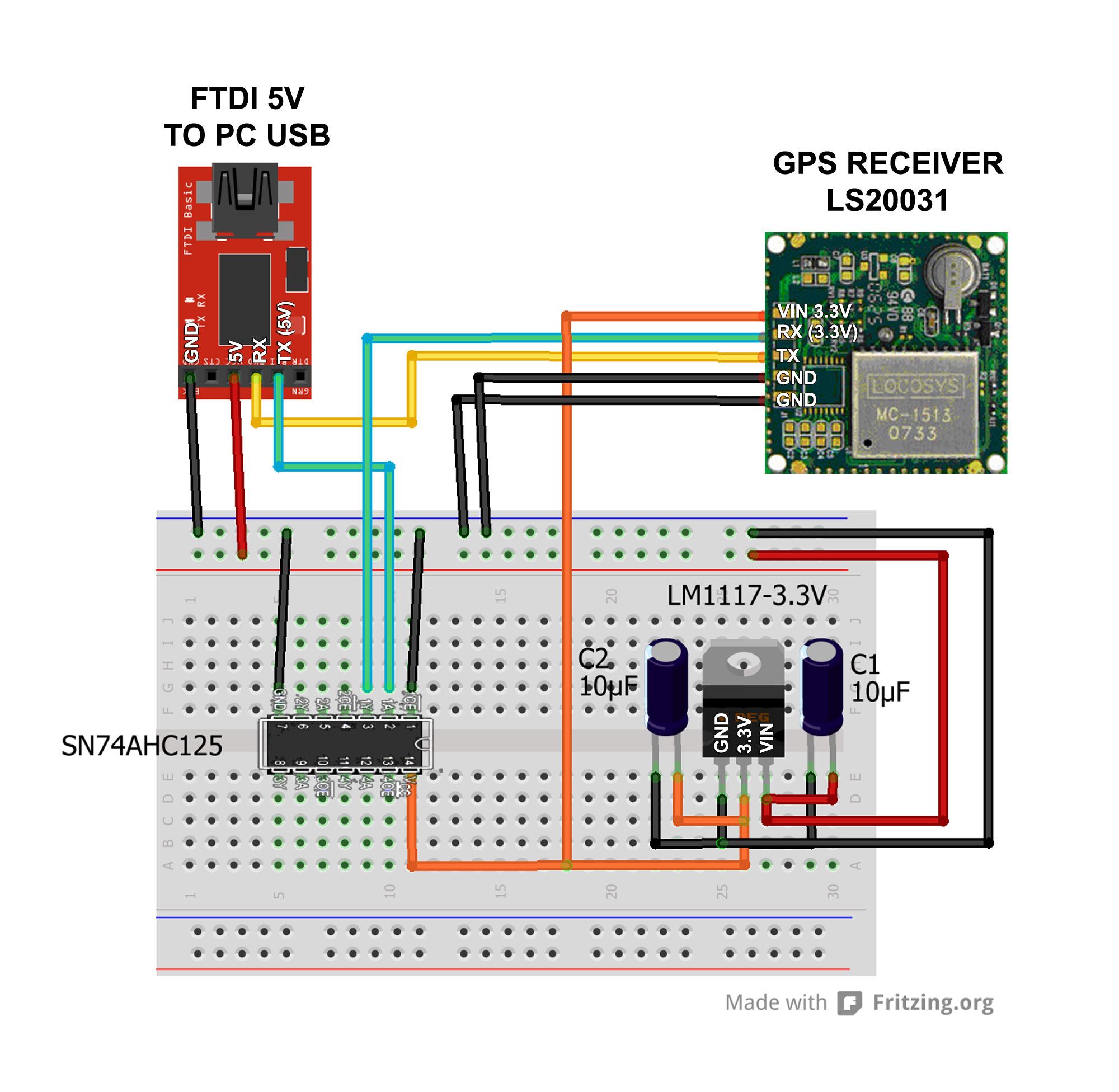
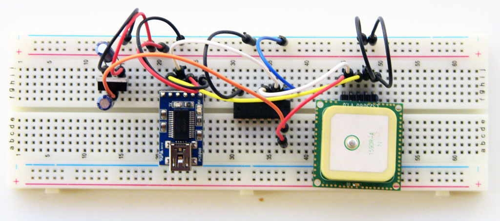
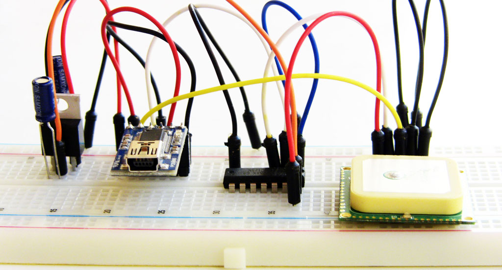
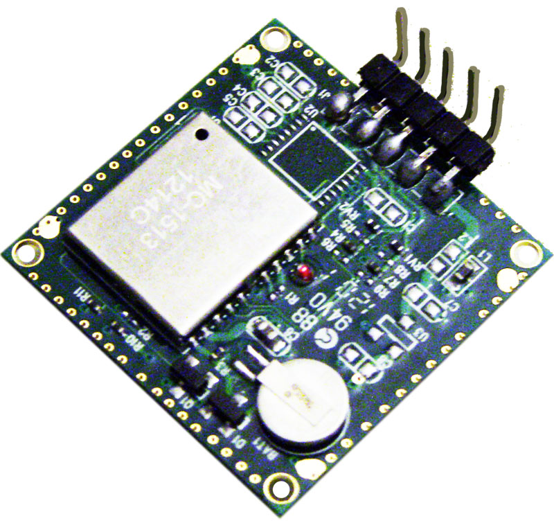
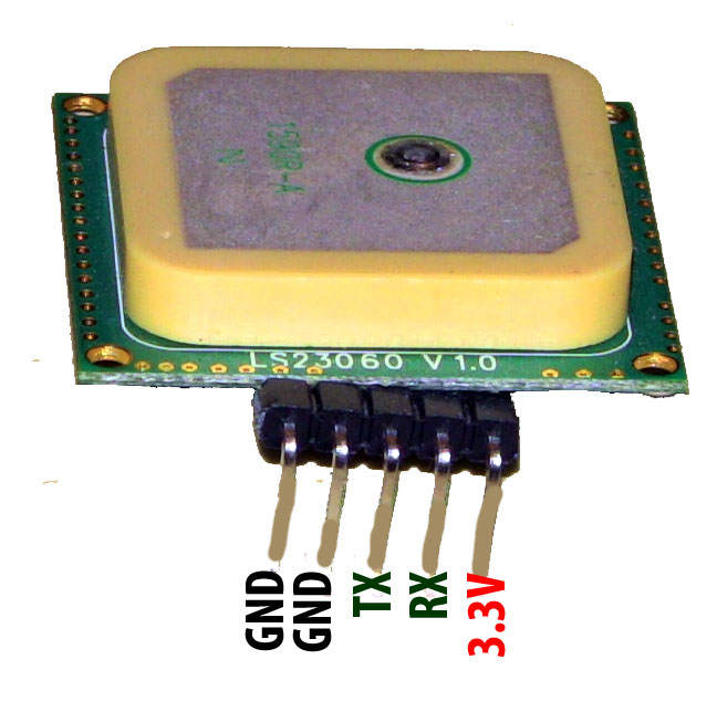
WIRING THE LS20031 GPS RECEIVER
- VIN......PIN2 (3.3V) which is the middle pin of the LM1117T regulator
- RX.......PIN3 (1Y) of SN74AHC125 IC
- TX.......RX pin of FTDI adapter
- GND...GND rail of breadboard
- GND...GND rail of breadboard
WIRING THE FTDI (5V) ADAPTER
- GND.....GND rail of breadboard
- CTS......NC
- 5V ........5V rail of breadboard
- RX........TX pin of the LS20031 GPS receiver
- TX.........PIN2 (1A) of the SN74AHC125 IC
- DTR.....NC
WIRING THE SN74AHC125 IC
- PIN1 (1OE) ........GND
- PIN2 (1A)............5V PIN of the FTDI adapter
- PIN3 (1Y) ............RX PIN of the LS20032 GPS receiver
- PIN7 (GND)........GND rail of breadboard
- PIN14 (VCC)......3.3V pin which is the middle pin of the LM1117 regulator
- PIN1 (GND)......GND of breadboard rail and to negative pins of the two 10uF electrolytic capacitors.
- PIN2 (3.3V).......VIN pin of the LS20031 and PIN14 of the SN74AHC125 IC and to the positive pin of the first 10uF electrolytic capacitor
- PIN3 (VIN).........5V pin of FTDI adapter and to the positive pin of the second 10uF electrolytic capacitor
Using MiniGPS 4.1 to Configure Your LS20031 GPS Receiver
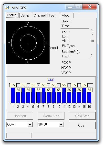
Once the wiring is done, the next step is to hookup the prototype to the PC via the FTDI adapter and run MiniGPS 1.4. MiniGPS is a nifty utility that does three things:
MiniGPS communicates with the LS20031 GPS receiver over COM ports.
The first and most important task once you run MiniGPS is to make sure it knows which COM port your FTDI is talking to on your PC and at what baud rate.
DETECTING COM PORT AND BAUD RATE
If you don't know the COM port setting for the GPS receiver or the baud rate, this is where Tera Term comes in handy if you are not a fan of the Control Panel and if you don't care for trying 3 dozen COM ports to find the correct one.
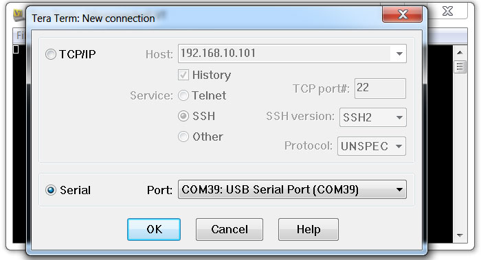
When you run Tera Term the opening window will present you with two options for a new connection. One of those two options is a Serial connection radio button. Adjacent to this Serial radio button is a "Port" field that lists available com ports. The one that says USB Serial Port is the com port of interest. (See attached figure).
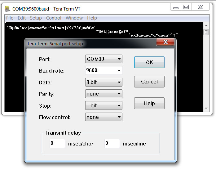
Select this Serial port and click OK. If you see garbage printed on the Tera Term screen, then you have the wrong baud rate. Go to the Setup/Serial Port menu option. You will get a dialog box with many drop down menus. Find the Baud rate menu and start from 57600, which is the default LS20031 baud rate, and see if you get legible NMEA sentences on the Tera Term screen.
BACK TO MINIGPS
From the MiniGPS Status window, change the COM port and baud rate to the desired values using the drop down menus at the bottom of the window then click the Open button.
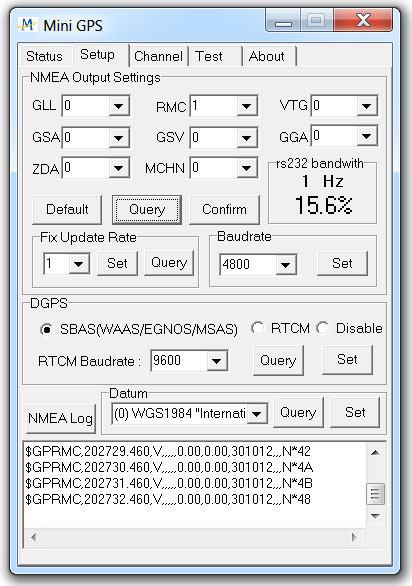
Now click on the "Setup" tab (see figure) to see if MiniGPS is receiving data from the GPS receiver. The GPS receiver will send data (aka NMEA sentences) even if it has no satellite fix. You will see those NMEA sentence scroll at the bottom of the Setup window.
If you are using the LS20031 for the first time, you will see too much unintelligible text data scrolling past. These NMEA output messages include numbers and letters. The numbers contain date/time info, latitude longitude speed, altitude, direction, satellite info, etc. Since that's too much info, you can select to receive a subset of this info. Not only that, you can also select how often we receive this info per second.
NMEA SENTENCES
NMEA stands for National Marine Electronics Association. This is the industry body that comes up with standardized message formats for GPS receivers to simplify using this technology.
NMEA sentences start with GP + Three letter identifier that tells us what sort of data contained in this sentence being transmitted by the GPS receiver.
The LS20031 sends out the following NMEA sentences.
$GPRMC,053740.000,A,2503.6319,N,12136.0099,E,2.69,79.65,100106,,,A*53
HOW TO CHANGE GPS RECEIVER SETTINGS
For my GPS logger (to be published in my next guide), I want to make the following changes to the settings of the LS20031 GPS receiver using the MiniGPS utility.
2) Because 57600 baud is too fast for my GPS logger, I will drop it down to 4800 baud. In the Setup window, there's an area titled Baudrate with a drop down menu. I will pick 4800 then click the Set button next to the menu and wait for a confirmation.
3) Finally, in the Fix Update Rate area, I want to pick 1 from the drop down menu then click the Set button next to it. A confirmation message will tell me if the GPS receiver was updated.
When I change the baud rate for my GPS receiver, I need to remember next time I run MiniGPS to change the baud rate accordingly. I also need to update any code with the proper baud rate if I am writing a program to talk to the GPS receiver. Forgetting to do this will cause unnecessary aggravation.
Now I am ready to make use of the data generated by the GPS receiver.
- Read the location updates from the GPS receiver and other useful data, also known as NMEA sentences
- Read settings of of your GPS receiver such as baud rate, speed and frequency of updates, what NMEA messages it's sending.
- Change the settings of your GPS receiver such as baud rate and type of messages you want to receive from the GPS receiver.
MiniGPS communicates with the LS20031 GPS receiver over COM ports.
The first and most important task once you run MiniGPS is to make sure it knows which COM port your FTDI is talking to on your PC and at what baud rate.
DETECTING COM PORT AND BAUD RATE
If you don't know the COM port setting for the GPS receiver or the baud rate, this is where Tera Term comes in handy if you are not a fan of the Control Panel and if you don't care for trying 3 dozen COM ports to find the correct one.
When you run Tera Term the opening window will present you with two options for a new connection. One of those two options is a Serial connection radio button. Adjacent to this Serial radio button is a "Port" field that lists available com ports. The one that says USB Serial Port is the com port of interest. (See attached figure).
Select this Serial port and click OK. If you see garbage printed on the Tera Term screen, then you have the wrong baud rate. Go to the Setup/Serial Port menu option. You will get a dialog box with many drop down menus. Find the Baud rate menu and start from 57600, which is the default LS20031 baud rate, and see if you get legible NMEA sentences on the Tera Term screen.
BACK TO MINIGPS
From the MiniGPS Status window, change the COM port and baud rate to the desired values using the drop down menus at the bottom of the window then click the Open button.
Now click on the "Setup" tab (see figure) to see if MiniGPS is receiving data from the GPS receiver. The GPS receiver will send data (aka NMEA sentences) even if it has no satellite fix. You will see those NMEA sentence scroll at the bottom of the Setup window.
If you are using the LS20031 for the first time, you will see too much unintelligible text data scrolling past. These NMEA output messages include numbers and letters. The numbers contain date/time info, latitude longitude speed, altitude, direction, satellite info, etc. Since that's too much info, you can select to receive a subset of this info. Not only that, you can also select how often we receive this info per second.
NMEA SENTENCES
NMEA stands for National Marine Electronics Association. This is the industry body that comes up with standardized message formats for GPS receivers to simplify using this technology.
NMEA sentences start with GP + Three letter identifier that tells us what sort of data contained in this sentence being transmitted by the GPS receiver.
The LS20031 sends out the following NMEA sentences.
- GGA Global positioning system fixed data
- GLL Geographic position - latitude/longitude
- GSA GNSS DOP and active satellites
- GSV GNSS satellites in view
- RMC Recommended minimum specific GNSS data
- VTG Course over ground and ground speed
$GPRMC,053740.000,A,2503.6319,N,12136.0099,E,2.69,79.65,100106,,,A*53
- Message ID: $GPRMC RMC protocol header
- UTC Time: 053740.000 hhmmss.sss
- Status A: A=data valid or V=data not valid
- Latitude: 2503.6319 ddmm.mmmm
- N/S: Indicator N N=north or S=south
- Longitude: 12136.0099 dddmm.mmmm
- E/W Indicator: E E=east or W=west
- Speed over ground: 2.69 knots True
- Course over ground: 79.65 degrees
- Date: 100106 ddmmyy
- Magnetic variation: degrees
- Variation sense: E=east or W=west (Not shown)
- Mode A: A=autonomous, D=DGPS, E=DR
- Checksum: *53
- <CR> <LF> End of message termination
HOW TO CHANGE GPS RECEIVER SETTINGS
For my GPS logger (to be published in my next guide), I want to make the following changes to the settings of the LS20031 GPS receiver using the MiniGPS utility.
- Turn off all NMEA messages from the LS20031 except the RMC message. Receive one RMC update per second instead of the maximum 5 updates.
- Lower the baud rate of the LS20031 from 57600 (default) to 4800 baud.
- Drop the frequency of GPS receiver from 10Hz to 1Hz.
2) Because 57600 baud is too fast for my GPS logger, I will drop it down to 4800 baud. In the Setup window, there's an area titled Baudrate with a drop down menu. I will pick 4800 then click the Set button next to the menu and wait for a confirmation.
3) Finally, in the Fix Update Rate area, I want to pick 1 from the drop down menu then click the Set button next to it. A confirmation message will tell me if the GPS receiver was updated.
When I change the baud rate for my GPS receiver, I need to remember next time I run MiniGPS to change the baud rate accordingly. I also need to update any code with the proper baud rate if I am writing a program to talk to the GPS receiver. Forgetting to do this will cause unnecessary aggravation.
Now I am ready to make use of the data generated by the GPS receiver.
Interfacing Google Earth to Your LS20031 GPS Receiver

There are two easy ways to interface the LS20031 GPS receiver to Google Earth.
For this to work, run Google Earth while your GPS receiver is in an open sky area to get a satellite fix. The LS20031's red led will start blinking soon as it gets a fix on 4 satellites. It can take the LS20031 over 30 seconds to get a satellite for a cold start and less than 5 seconds for a hot start. If your GPS receiver is connected properly, Google Earth will detect the COM port and baud rate automatically.
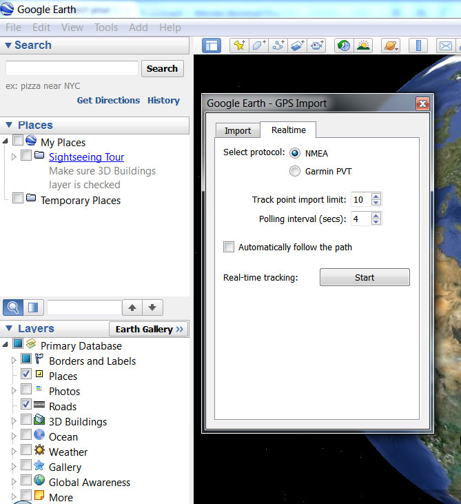
From Google Earth main menu select Tools then select GPS. This will open a dialog box with two tabs: Import and Realtime. Click the Realtime tab then click the NMEA radio button. Then click the Start button. Google will begin reading the NMEA data sent by the GPS receiver via the FTDI and will plot the coordinates on a map in real time.
GOOGLE EARTH - IMPORT NMEA LOG FILE
While running MiniGPS in an open sky area, click on the Status tab. Soon as the GPS receiver gets a satellite fix (GPS receiver LED will start blinking) the NMEA sentences at the bottom of the window will start scrolling with the correct location data.
Click the NMEA Log button, on top of the NMEA sentences scroll box, and provide a file name and directory for the log file. MiniGPS will now start recording the NMEA strings you see scrolling to the log file.
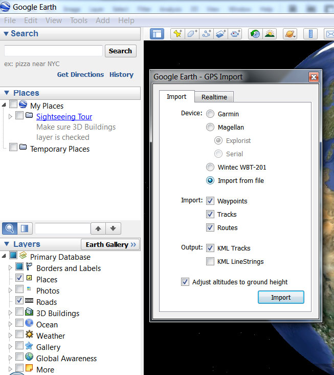
Exit MiniGPS. Run Google Earth. From the main menu, click the Tools menu then click GPS option. You will be presented with a dialog box with two tabs. Click on the Import tab. Then click Import from file radio button. You will be asked to select a file. Pick the NMEA log file you created from MiniGPS. Then watch Google Earth plot the location points.
Cool!
- Real time interface to the LS20031 via the FTDI adapter
- Import NMEA log file generated by MiniGPS
For this to work, run Google Earth while your GPS receiver is in an open sky area to get a satellite fix. The LS20031's red led will start blinking soon as it gets a fix on 4 satellites. It can take the LS20031 over 30 seconds to get a satellite for a cold start and less than 5 seconds for a hot start. If your GPS receiver is connected properly, Google Earth will detect the COM port and baud rate automatically.
From Google Earth main menu select Tools then select GPS. This will open a dialog box with two tabs: Import and Realtime. Click the Realtime tab then click the NMEA radio button. Then click the Start button. Google will begin reading the NMEA data sent by the GPS receiver via the FTDI and will plot the coordinates on a map in real time.
GOOGLE EARTH - IMPORT NMEA LOG FILE
While running MiniGPS in an open sky area, click on the Status tab. Soon as the GPS receiver gets a satellite fix (GPS receiver LED will start blinking) the NMEA sentences at the bottom of the window will start scrolling with the correct location data.
Click the NMEA Log button, on top of the NMEA sentences scroll box, and provide a file name and directory for the log file. MiniGPS will now start recording the NMEA strings you see scrolling to the log file.
Exit MiniGPS. Run Google Earth. From the main menu, click the Tools menu then click GPS option. You will be presented with a dialog box with two tabs. Click on the Import tab. Then click Import from file radio button. You will be asked to select a file. Pick the NMEA log file you created from MiniGPS. Then watch Google Earth plot the location points.
Cool!