Conduit Recorder/Whistle With Fusion 360
by Kevr102 in Workshop > 3D Printing
3886 Views, 37 Favorites, 0 Comments
Conduit Recorder/Whistle With Fusion 360
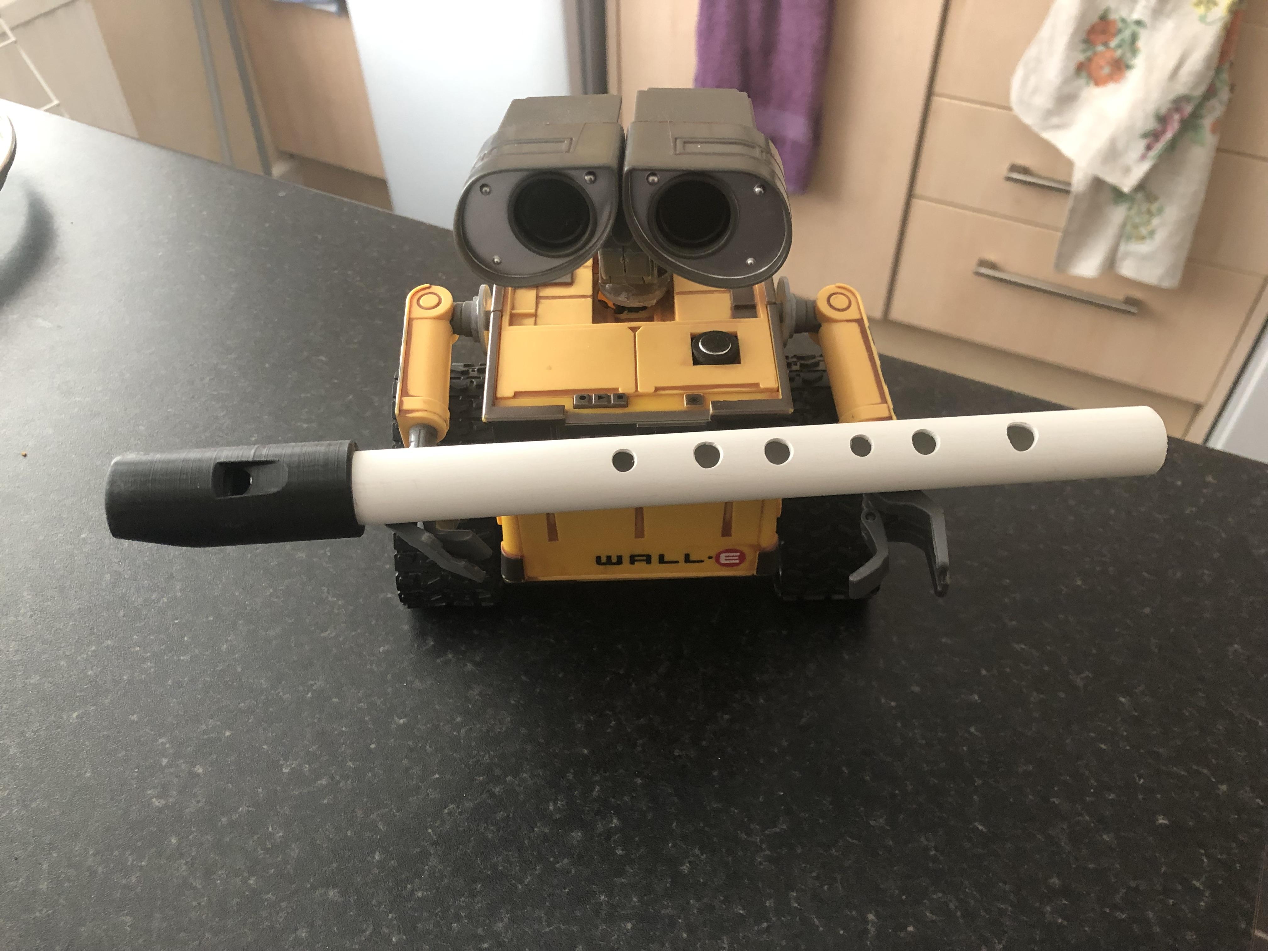
In this Instructable I will show you how I make a Recorder style Instrument out of a Piece of Electrical 20mm Plastic Conduit, I'm not sure what the actual title is for something like this as it only has 6 holes whereas a Recorder has more. it's more of a Penny Whistle on steroids!
I had surplus amounts of this conduit left over from rewiring the garage so I haven't had to buy anything for this project so to speak, I did have some 20mm Galvanised conduit as well but erred on the side of caution in case I dropped it on my foot or something.
This Instrument is not modelled on anything really, it's just something I fancied having a go at making and see what turned out.
Looking at other types of Instrument, the difficulty lies in the sound hole and getting that right so on that note!
Lets see if we can get a tune out of this Conduit:)
Supplies
Piece of Plastic 20mm conduit, this particular one 245mm
3D Printer
Fusion 360
CA Glue and Activator
Various drill sizes to include 6mm/7mm/8mm
Cutting the Conduit to Length and Drilling the Holes.
.png)
.png)
.png)
First attempt!
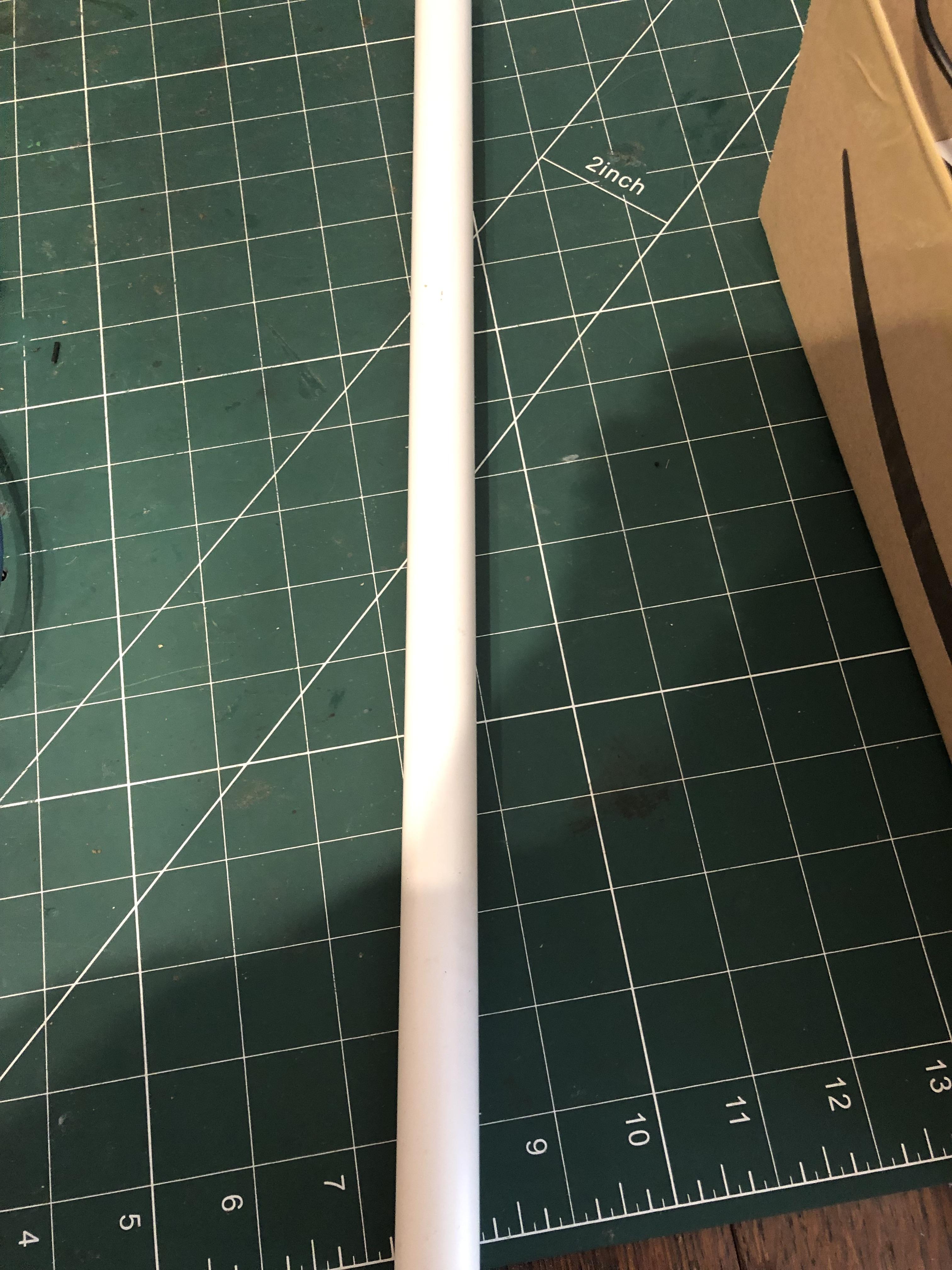
To start off with I'd cut the conduit at 350mm but soon realised that this was far too long so cut it down to 300mm I then cleaned the ends, with a de-burring tool for the inside and sandpaper for the outside, looking online I found a reference to holes on a flute or something being 1 Inch apart so this was my Benchmark, where to start the holes from is going to be purely guess work.
First of all I needed a straight line down the conduit to mark the holes off, I just took a pencil and held it between thumb and index, finger using the the joint of the 2nd finger as a guide this was ok..ish but I came across a video later of a guy scribing a line down a wooden pole, he placed the pole into one of the grooves on his table saw and then slid a thin board up to it and he scribed a perfect line, why didn't I think of that!
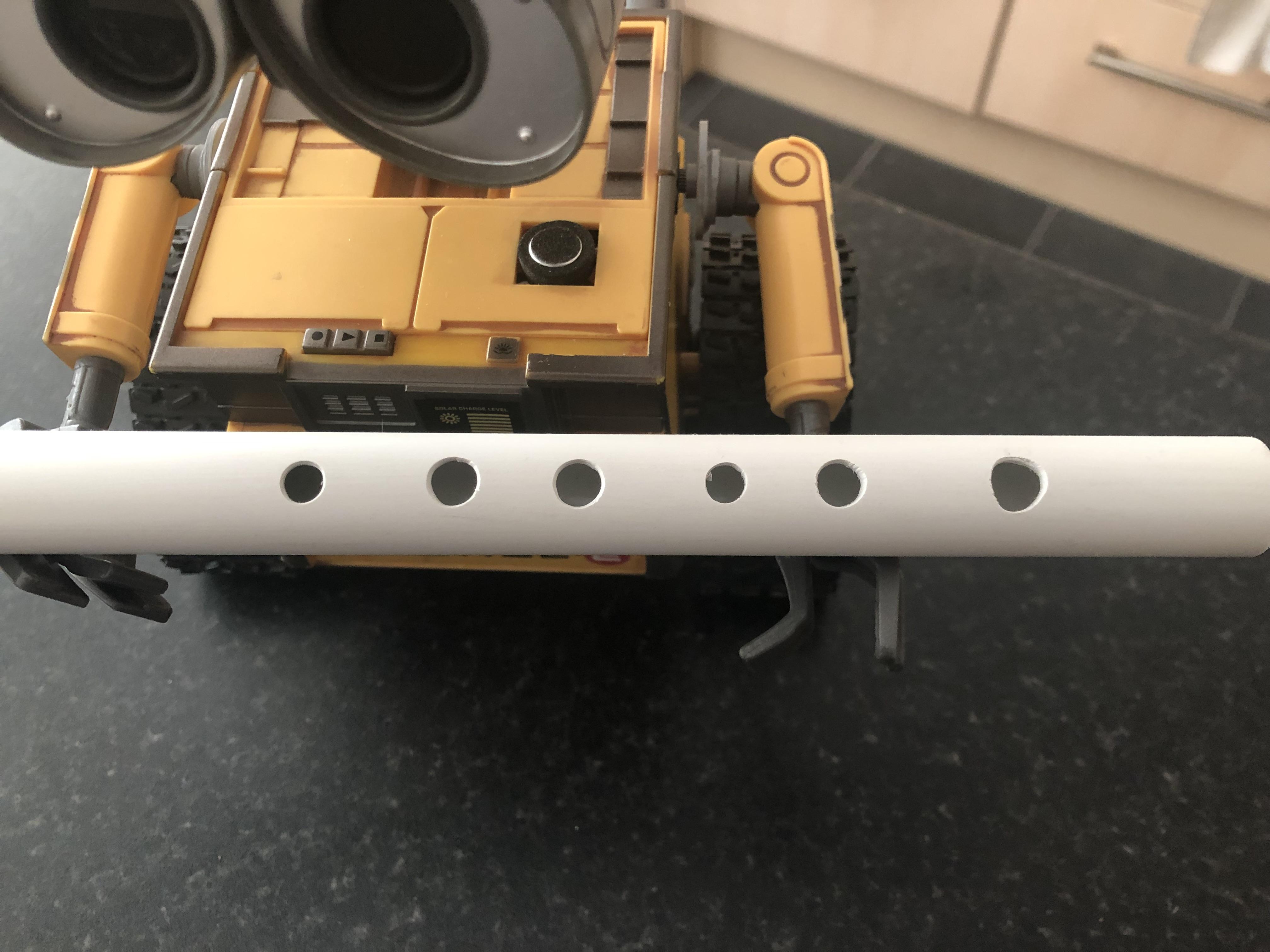
The next thing I ended up doing was to take a measurement from what would be the mouthpiece end of the conduit to 80mm and marked this off with a pencil, then with a gap of an inch I marked off another 8 holes, I didn't know at this point that I only needed 6 so cut it down to suit.
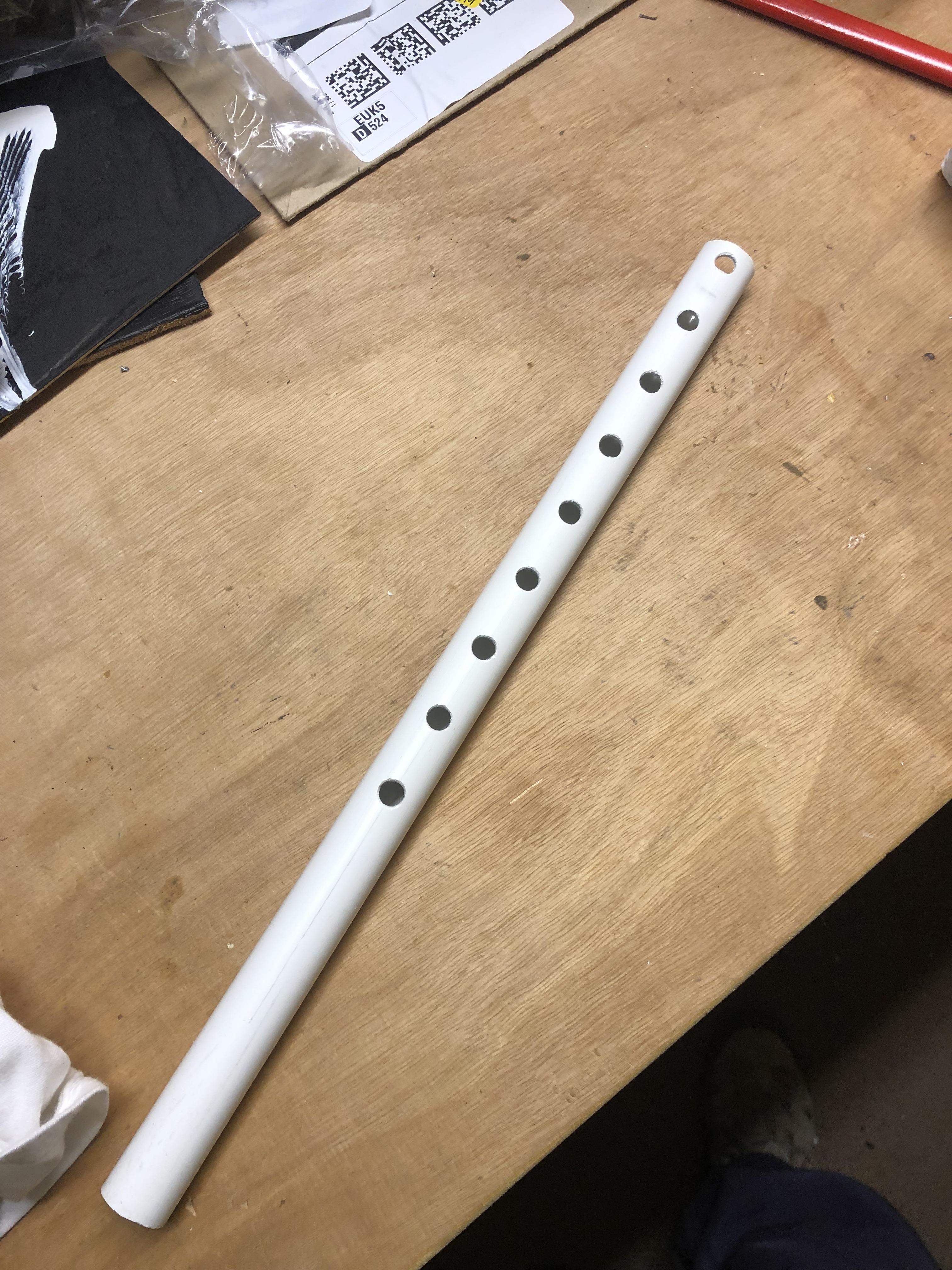
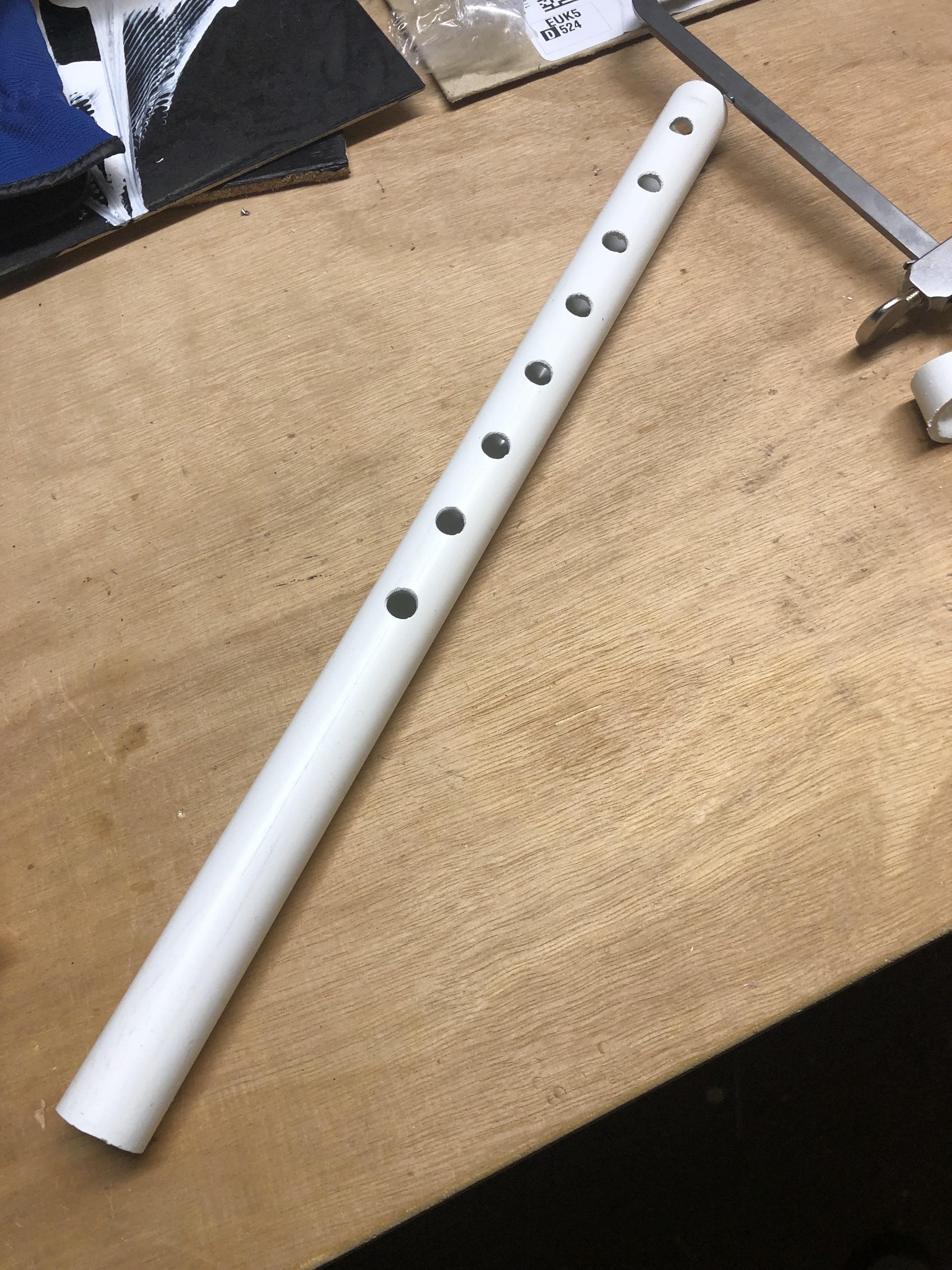
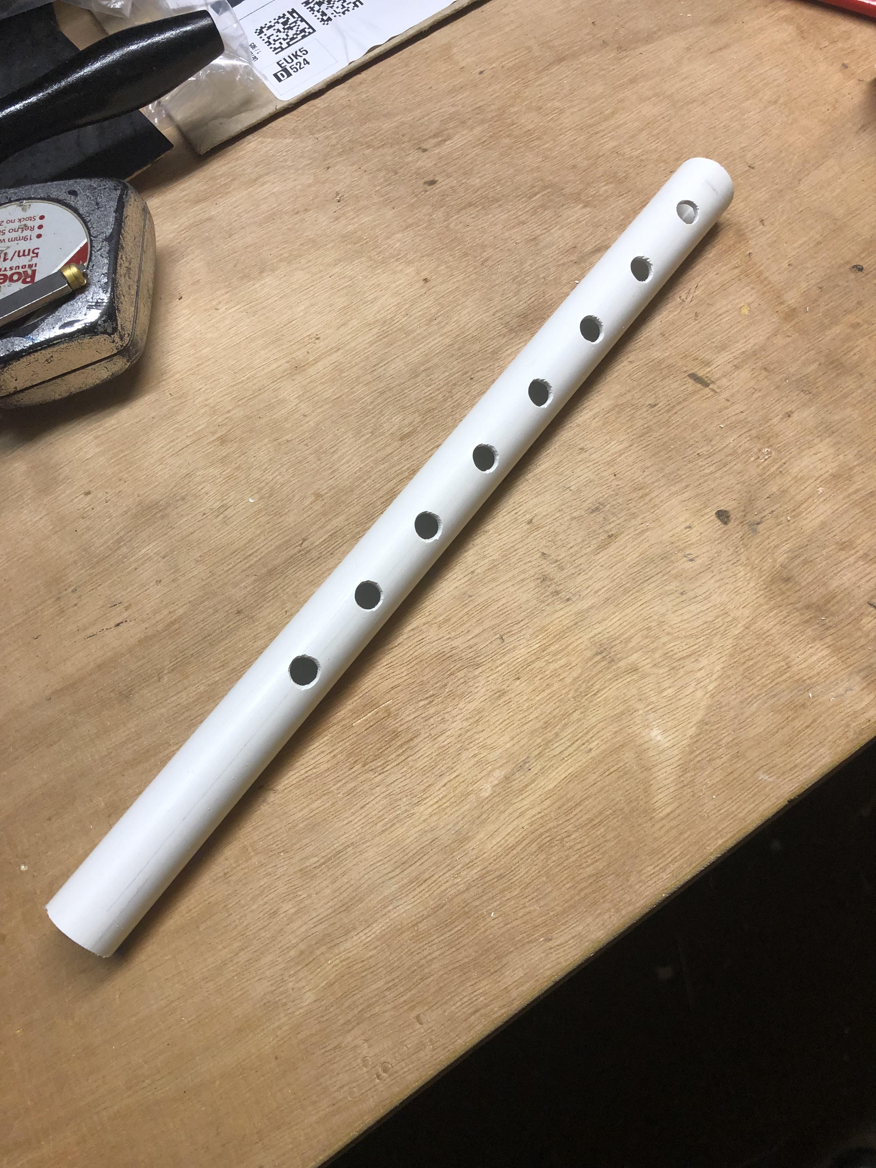
Initially I used a 7mm centre point drill bit to drill the holes and then cleaned the holes out with a de-burring tool and sanded the whole thing lightly, this first prototype played but I needed to cover half the hole sometimes to get the right note so clearly something wasn't right.
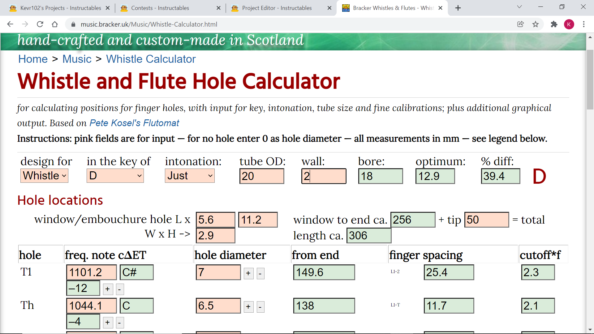
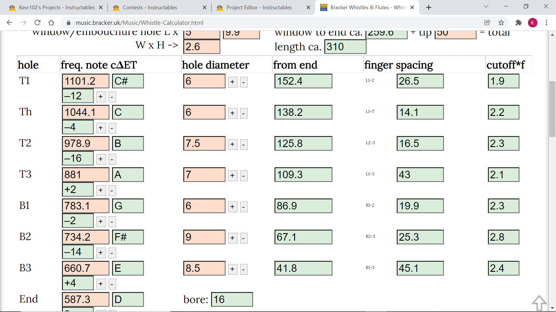
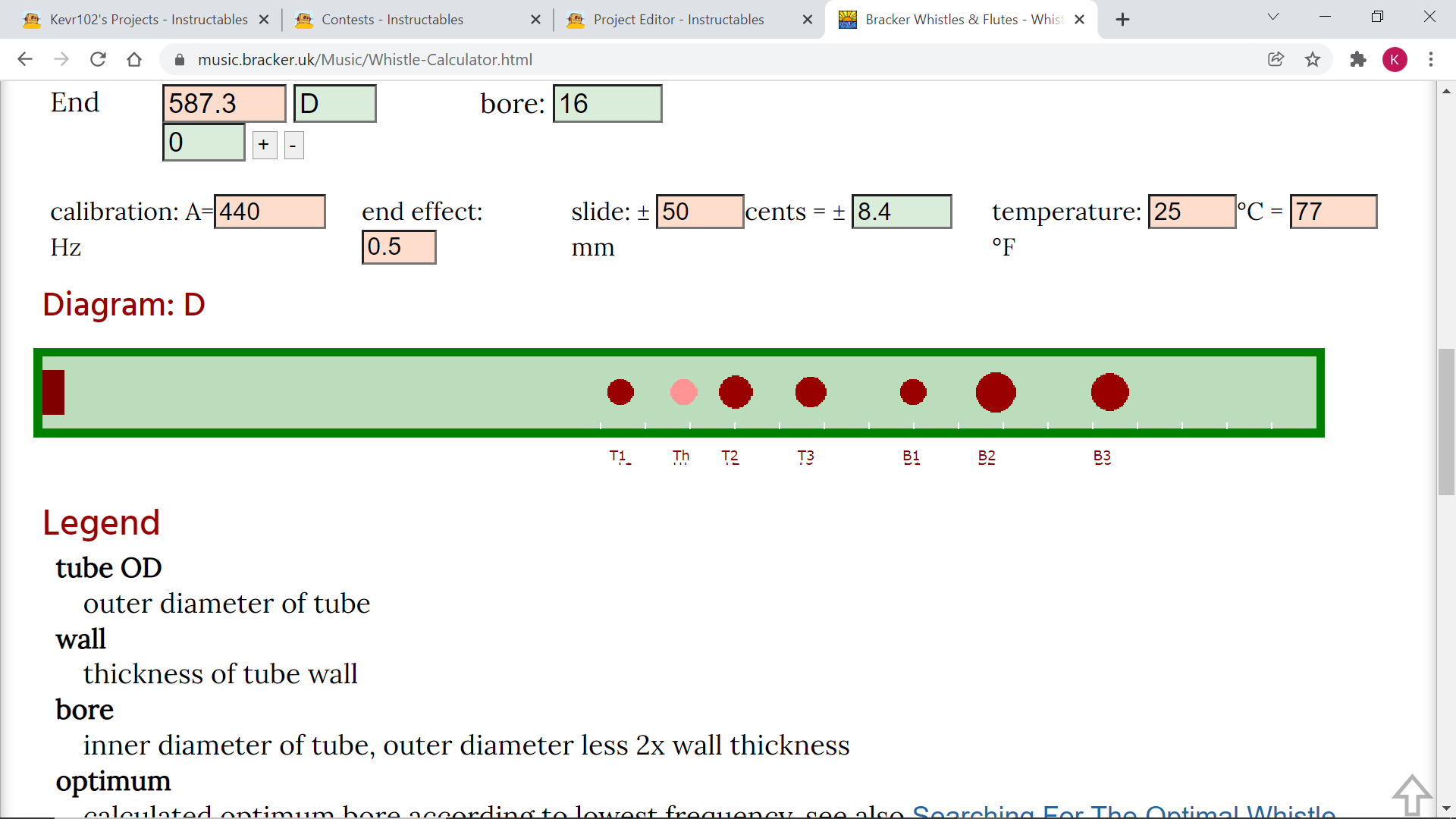
Looking further into this I found a more involved hole calculator which did the bore length and everything so this is what I used(see screen shots) I used what drills I had to hand for this, what's 0.5 of a mm between friends:)
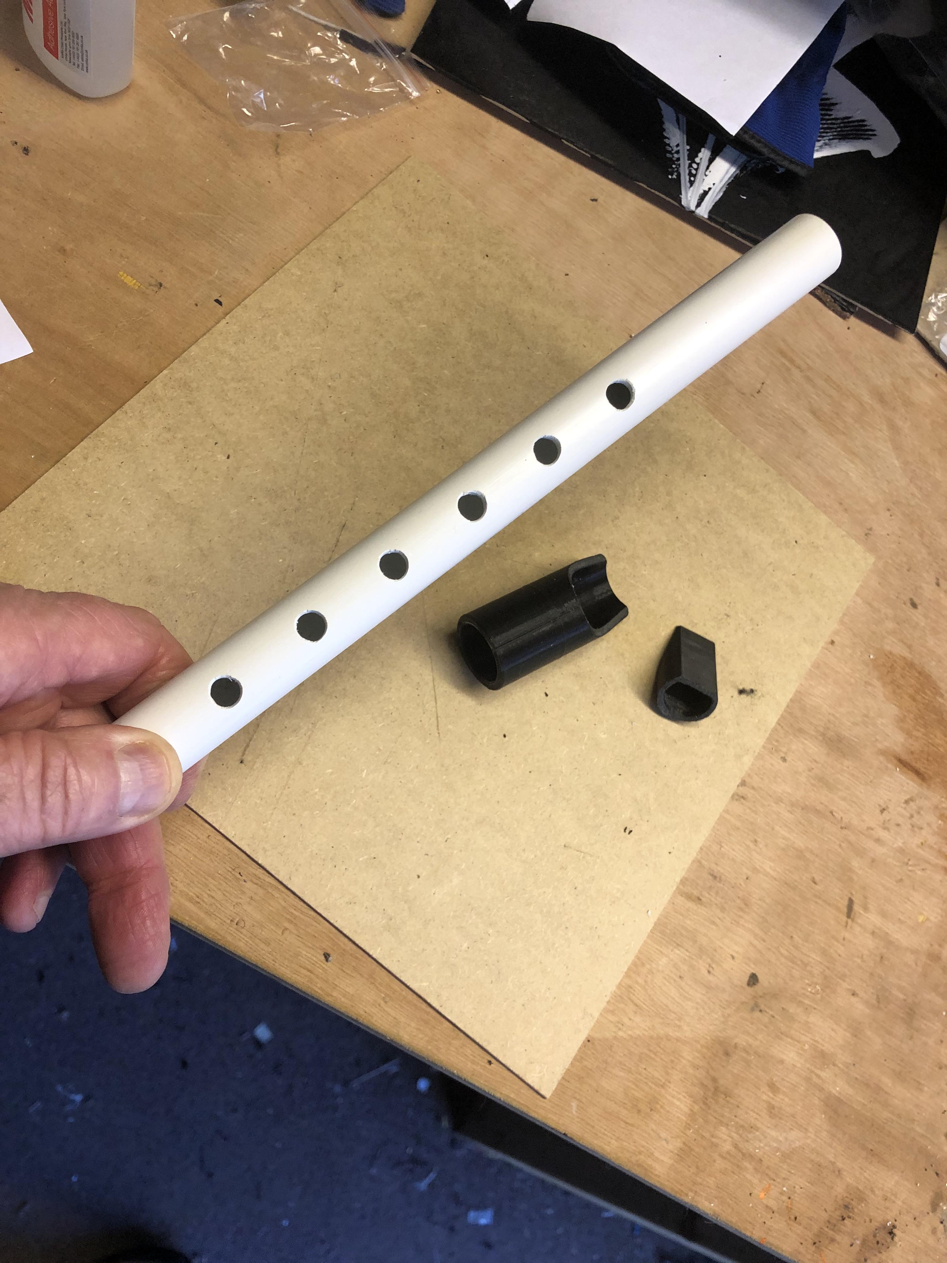
With the conduit drilled I de burred it, and lightly sanded and now time to design a mouth piece.
Some of the photos are of an earlier conduit with too many holes and all the holes were the same diameter, this whistle played and the notes were there but not necessarily in the right order:) I didn't know at this time that the holes had to be different diameters until I looked closer into the workings of a whistle, my 2nd attempt was much better.
Fusion 360 Mouthpiece and End Piece Design
.png)
.png)
.png)
.png)
.png)
.png)
.png)
.png)
.png)
.png)
.png)
.png)
.png)
.png)
.png)
.png)
.png)
.png)
.png)
.png)
.png)
.png)
.png)
.png)
.png)
.png)
.png)
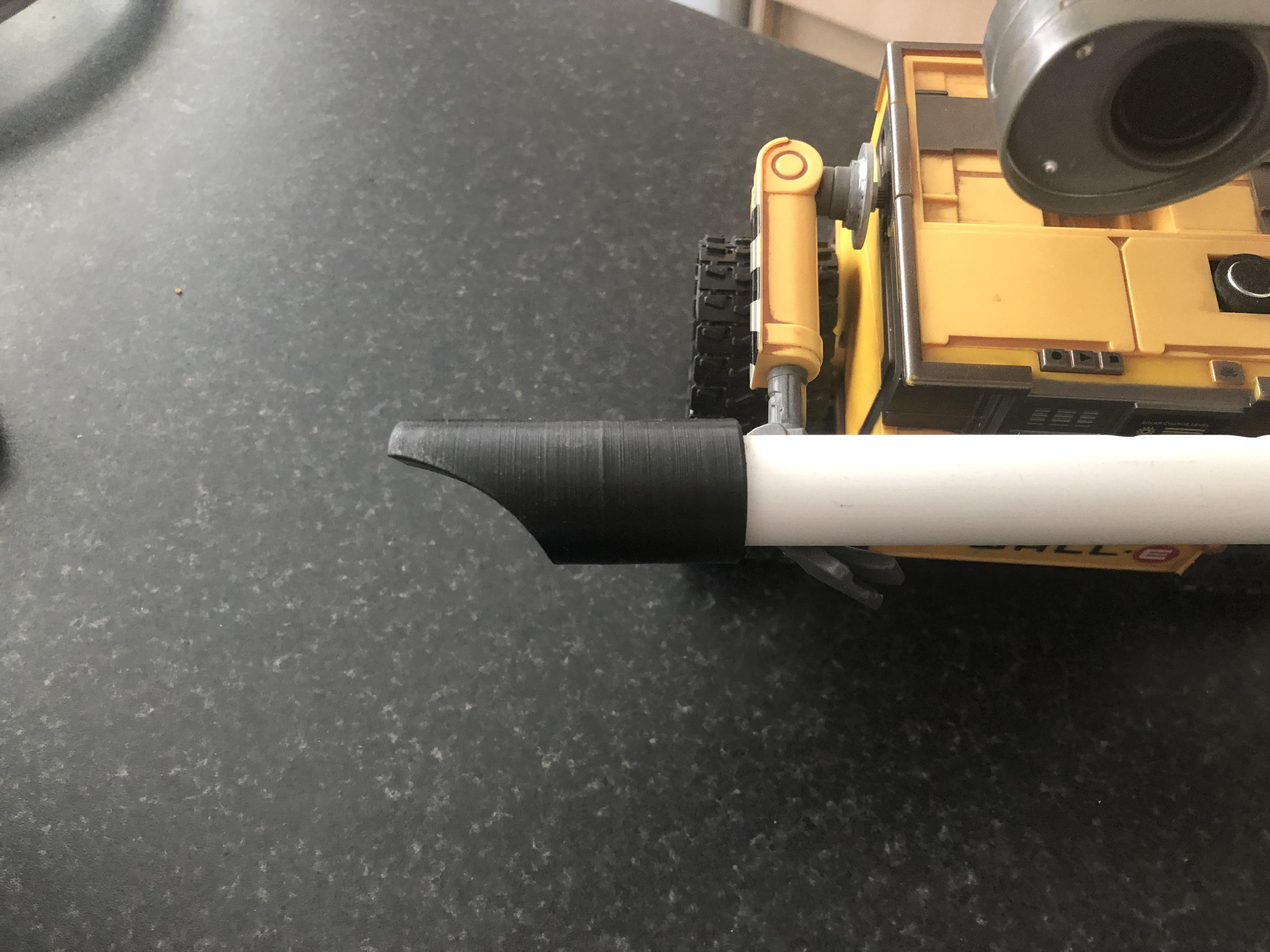
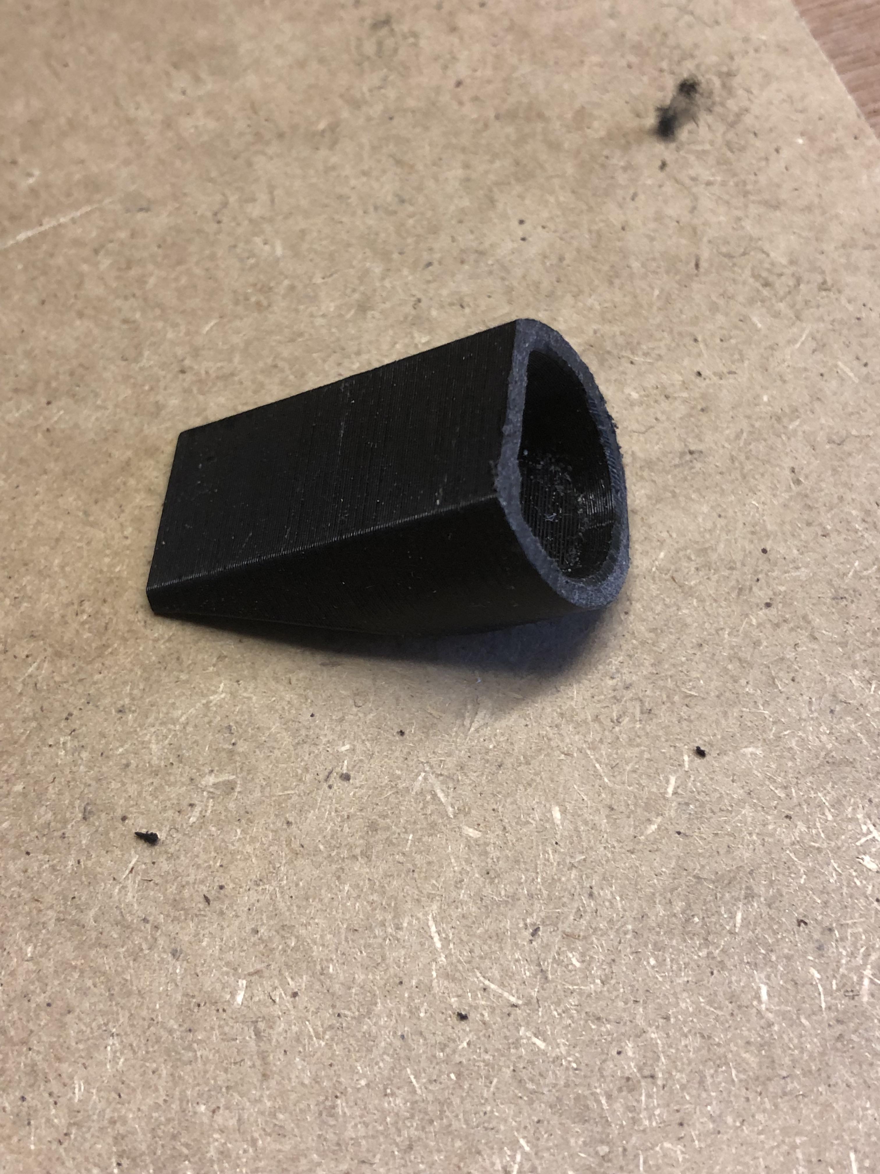
When I started this part I had no idea where to start, what shape or anything, but giving it some thought and thinking back to school day's I remembered how comfy a recorder mouthpiece was to play, not that I could play it! so with that shape in my head it was time to start.
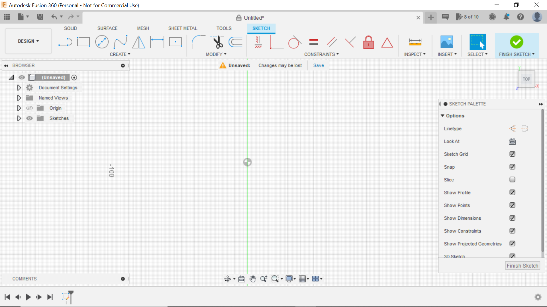
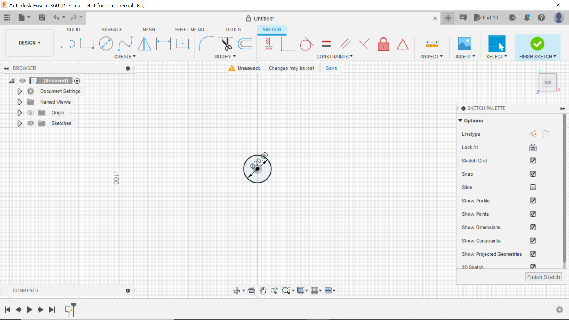
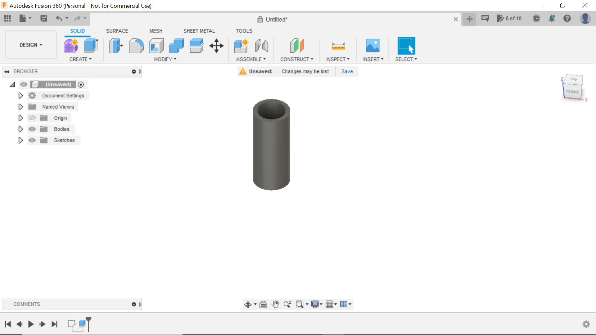
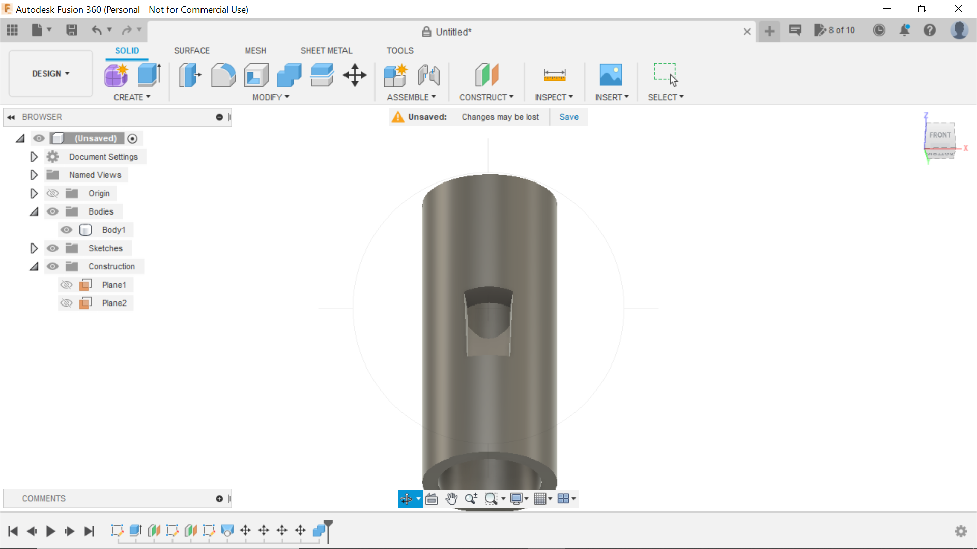
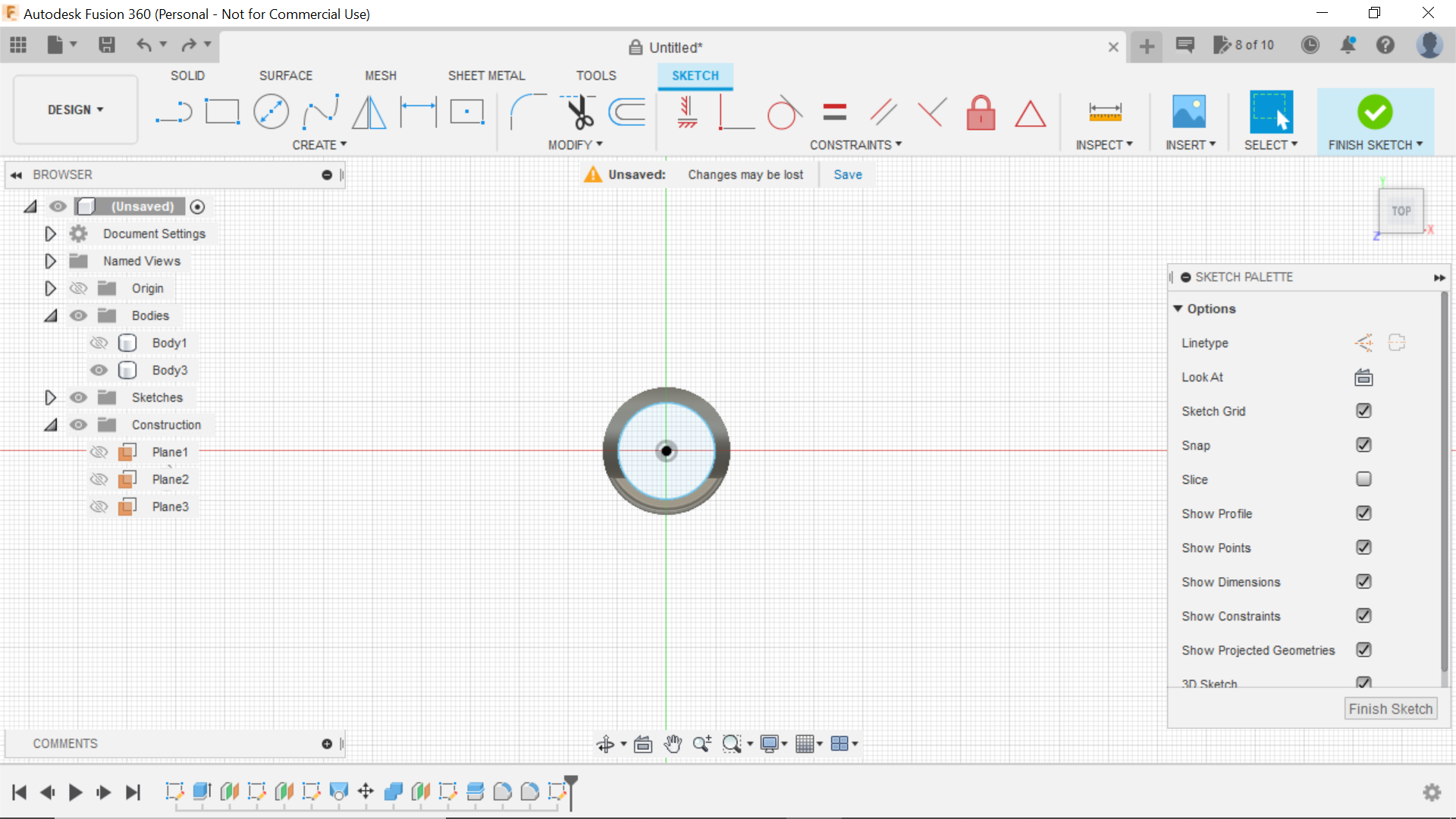
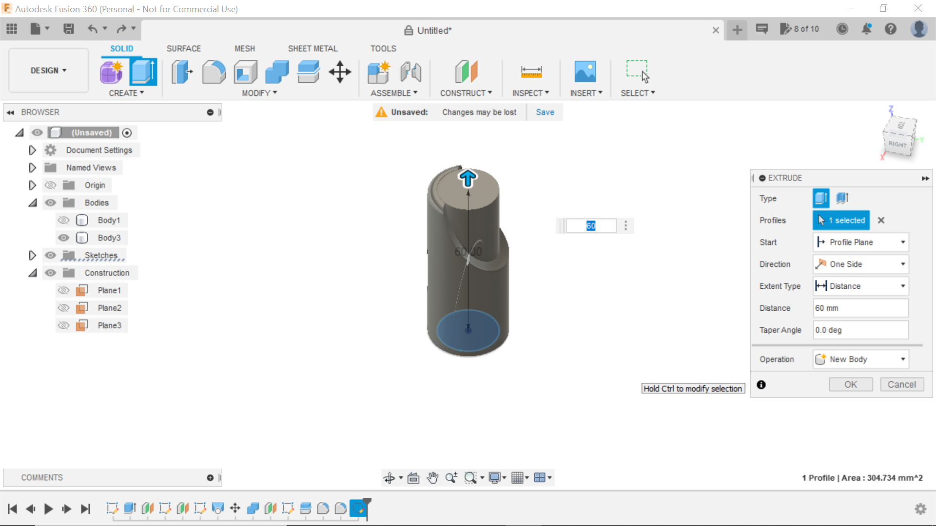
In Fusion 360 and Opting for the top plane, The conduit external diameter was 19.64mm I would use this as my first centre circle and then offset to 3mm for the Wall thickness, this circle was then extruded to 60mm Finish Sketch.
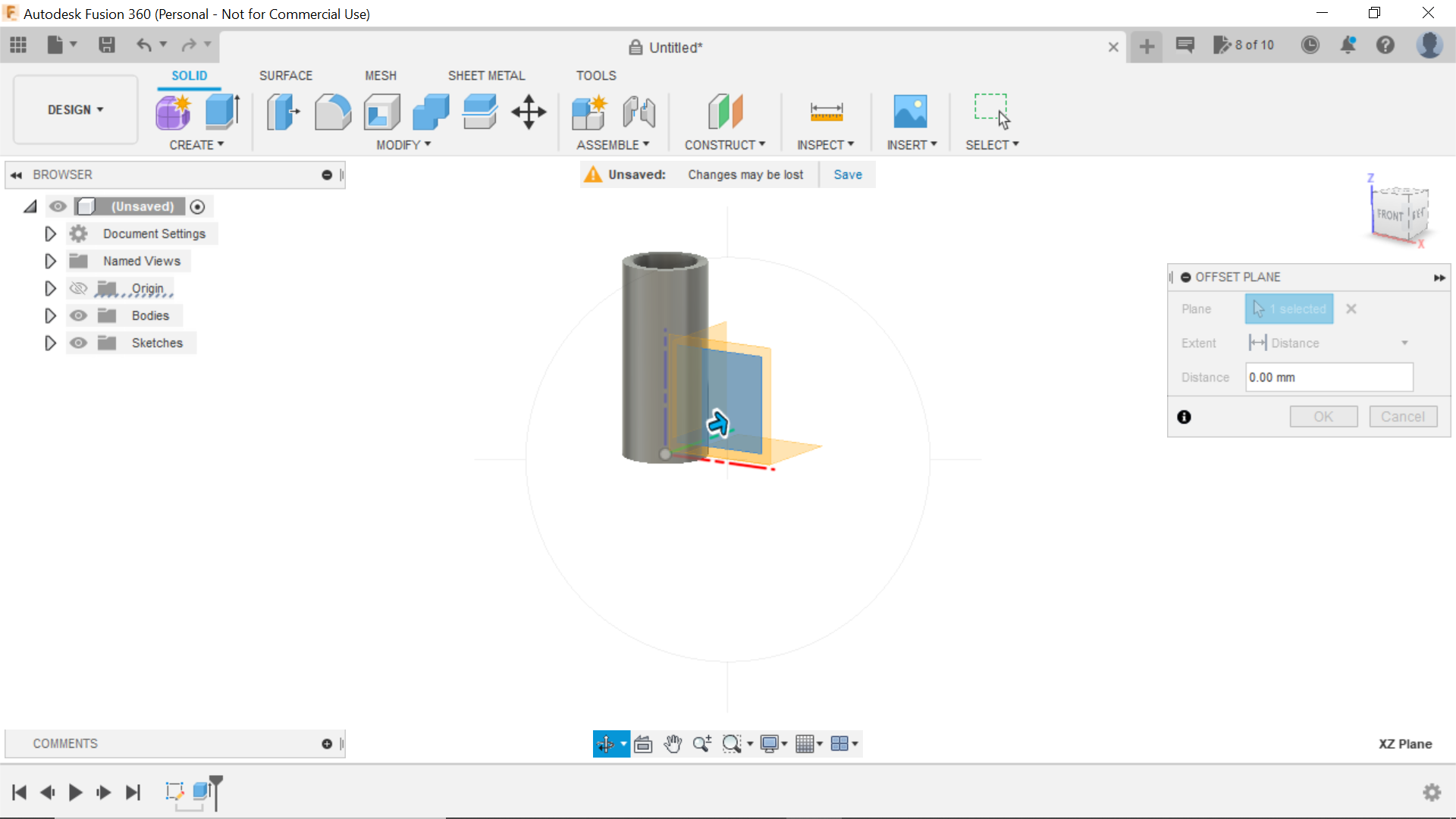
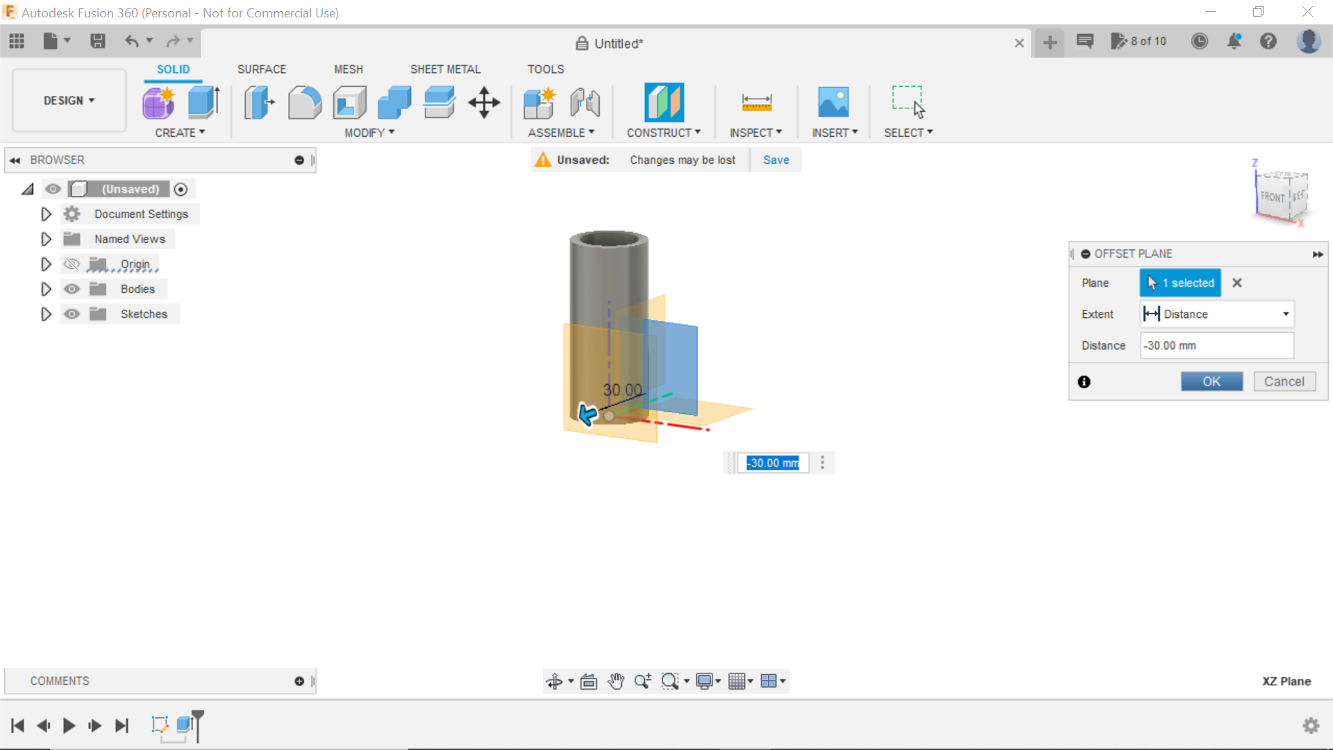
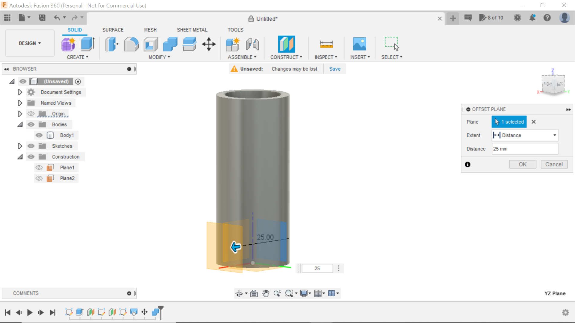
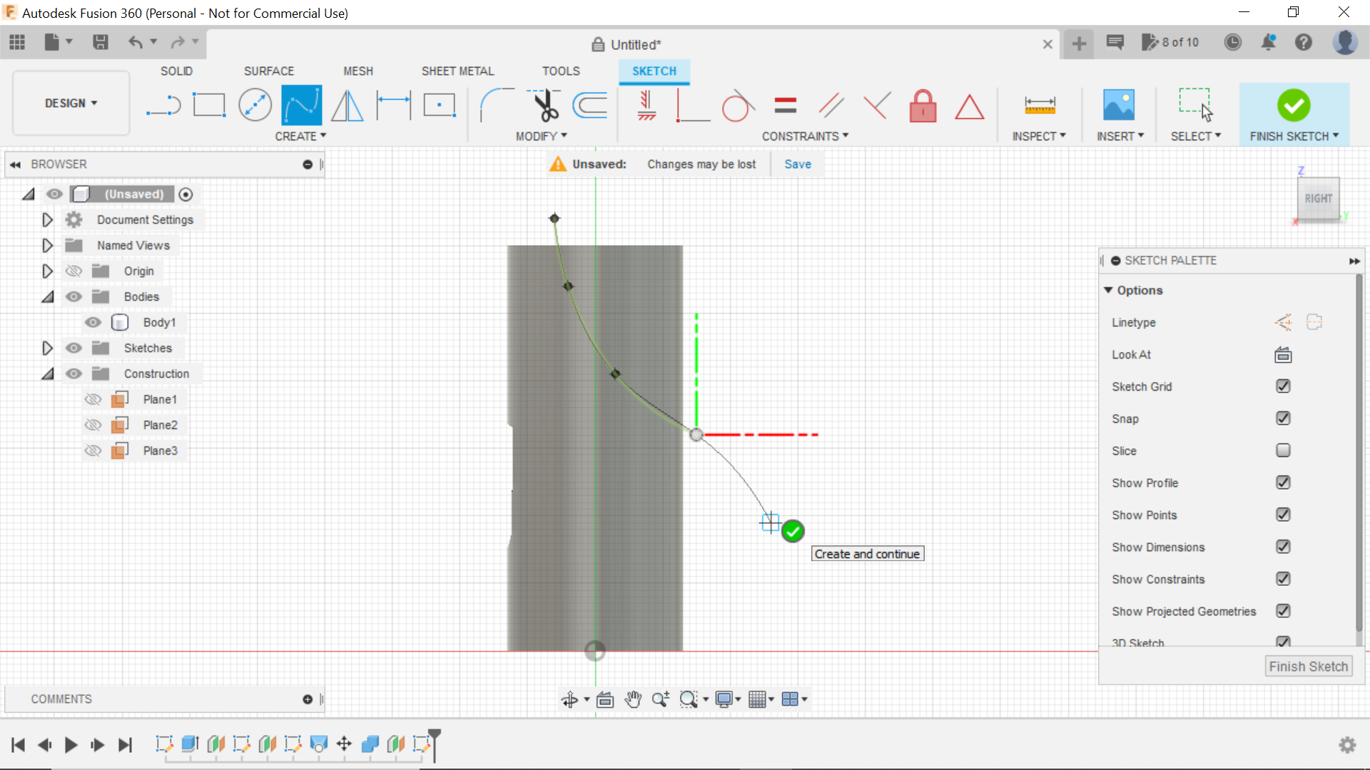
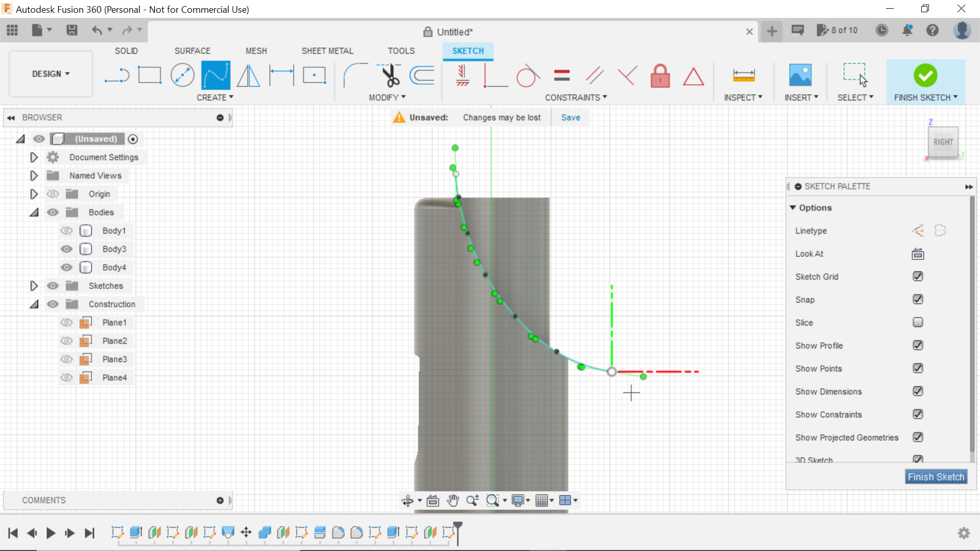
Using the offset plane tab, and using the right side view I moved the centre plane out -30mm then selecting this plane we create new sketch and using the Fit Point Tool Tab and started above the top of the extruded circle sketched a line that resembled the mouthpiece on a recorder, this line was also extended to beyond the design.
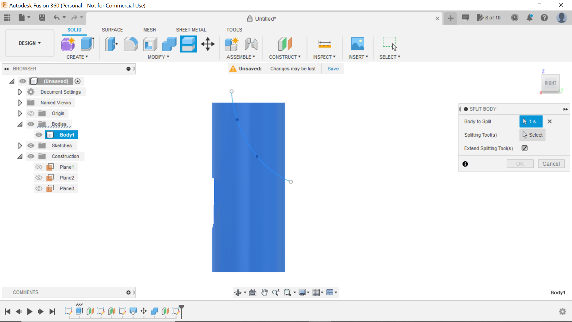
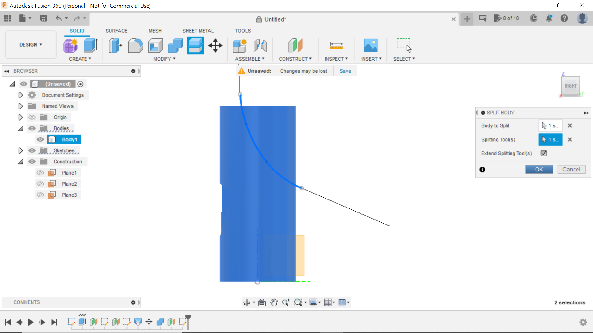
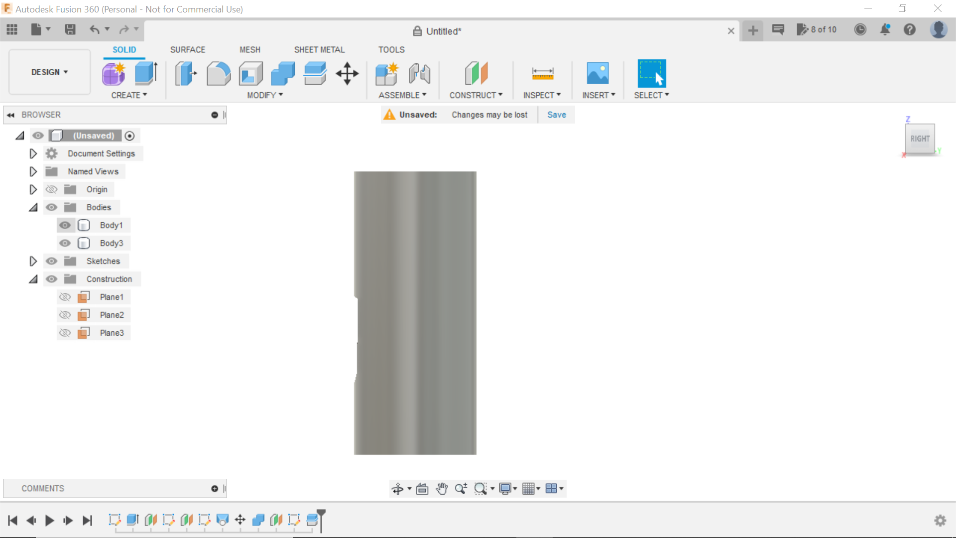
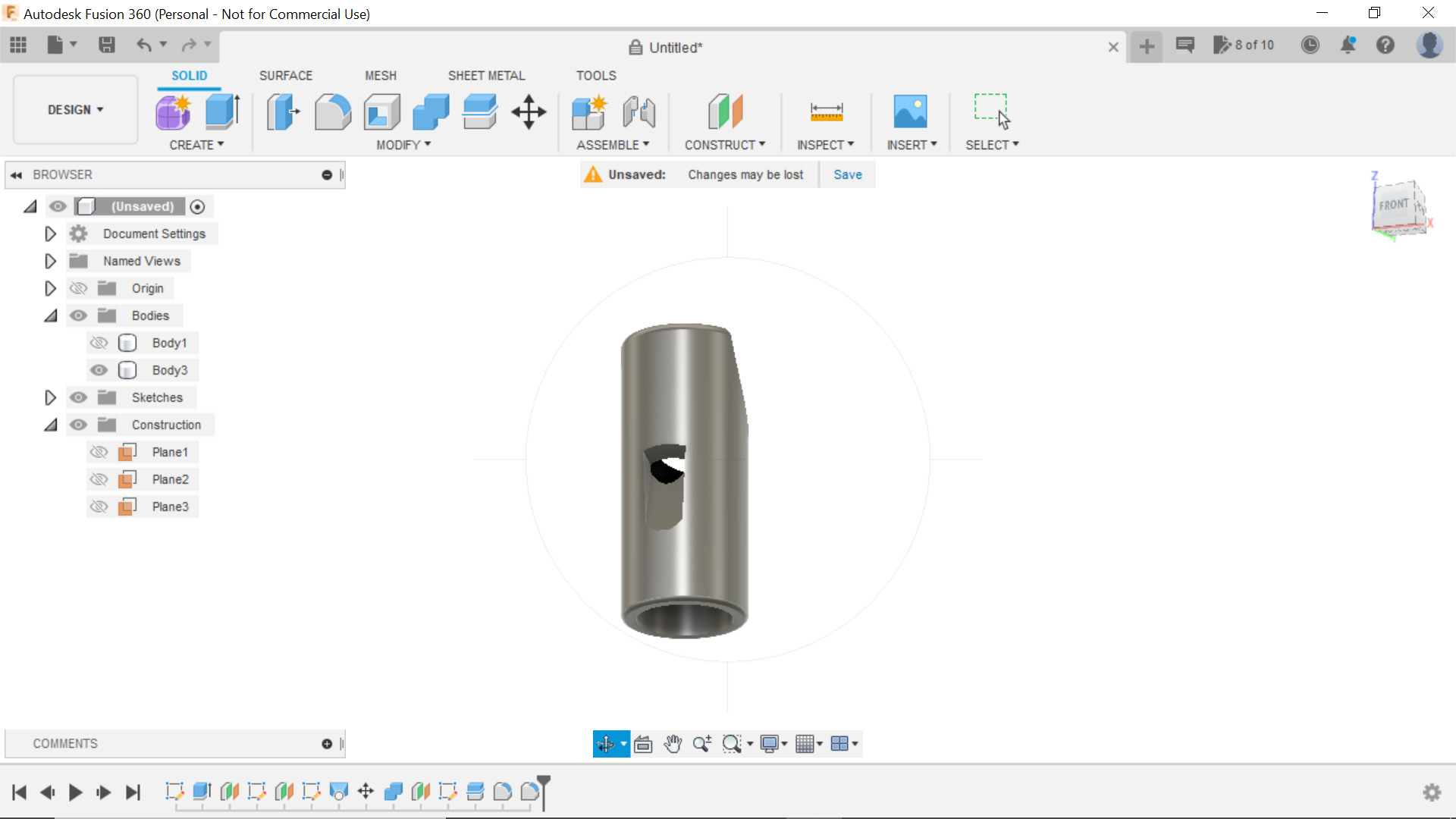
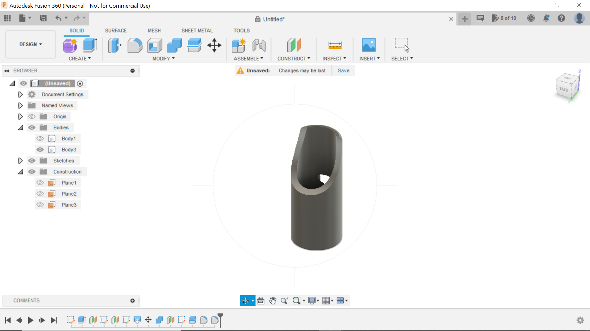
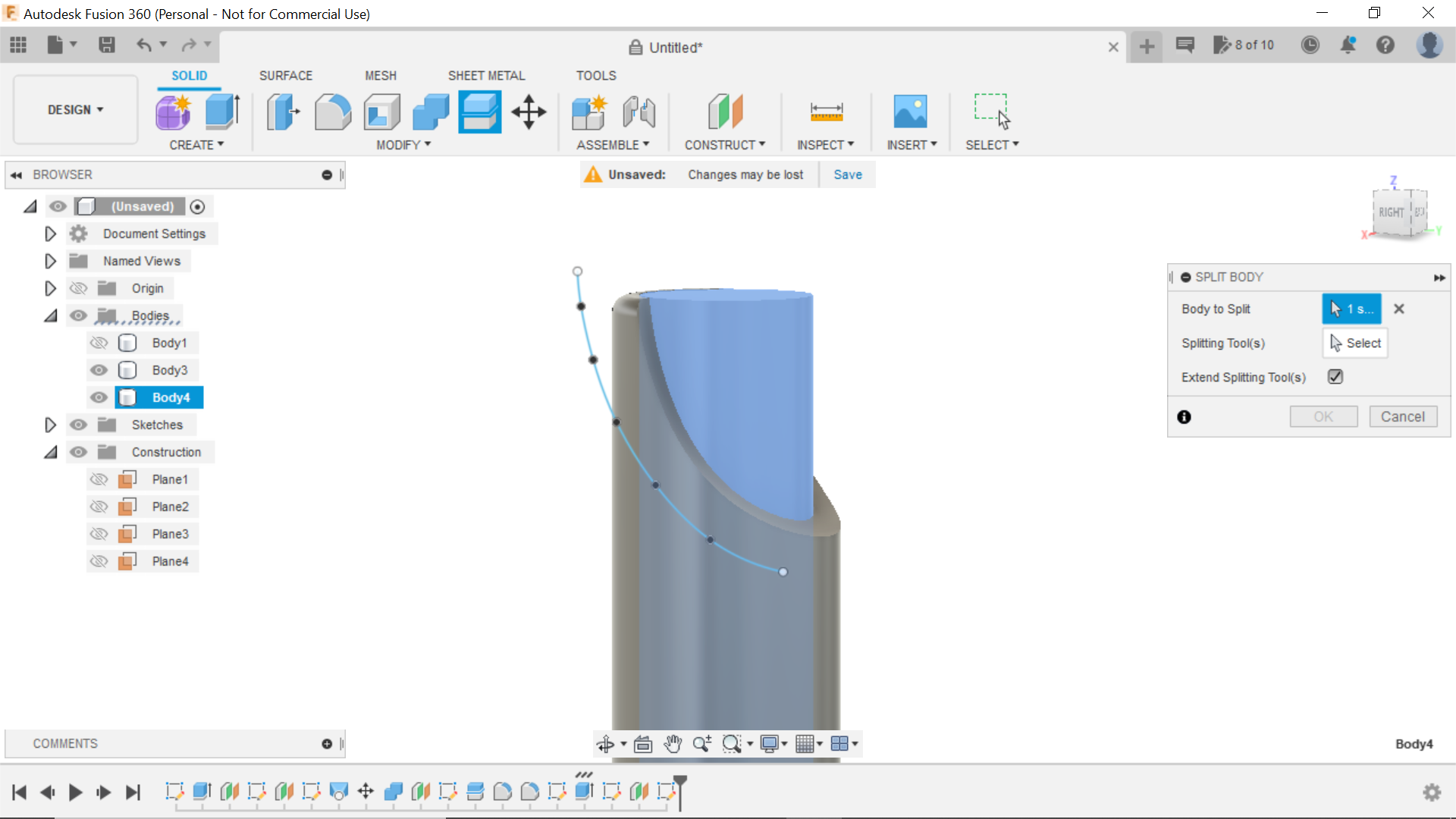
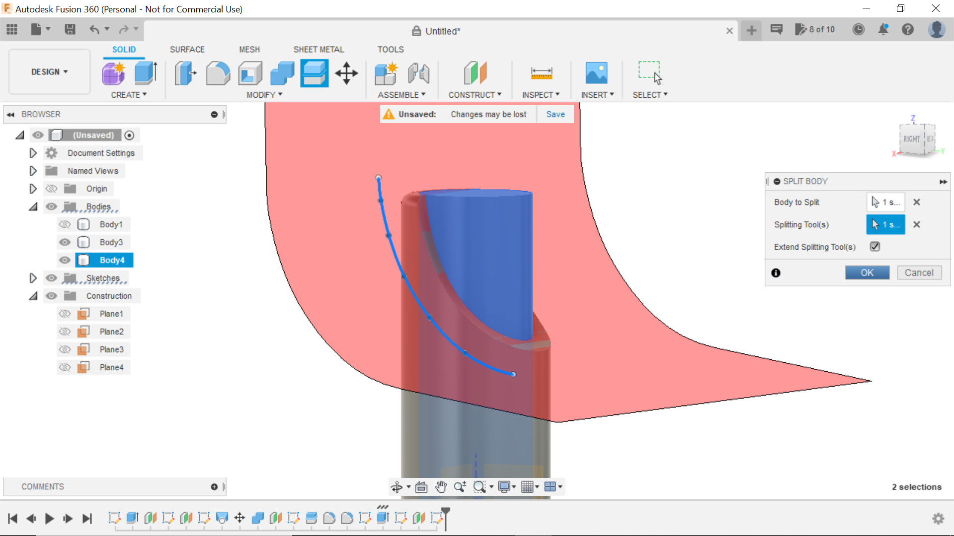
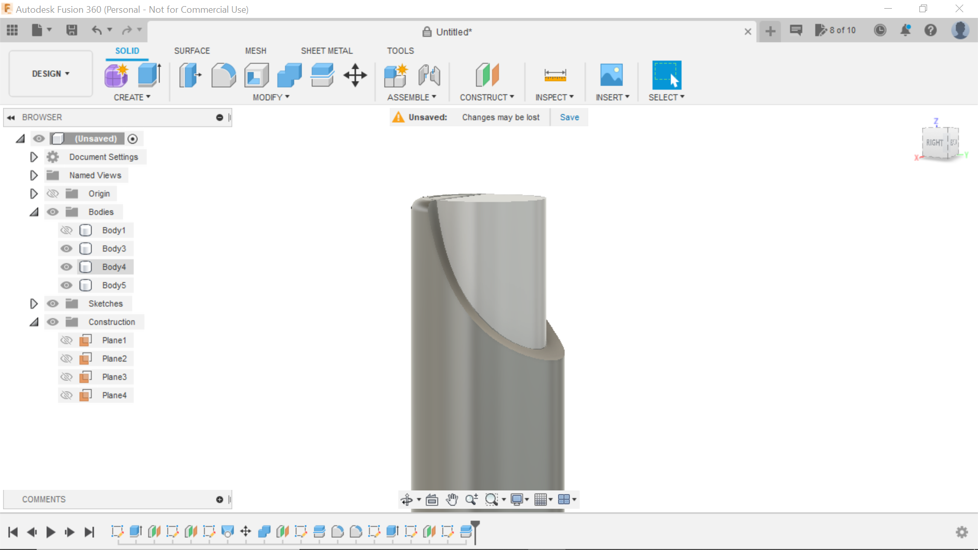
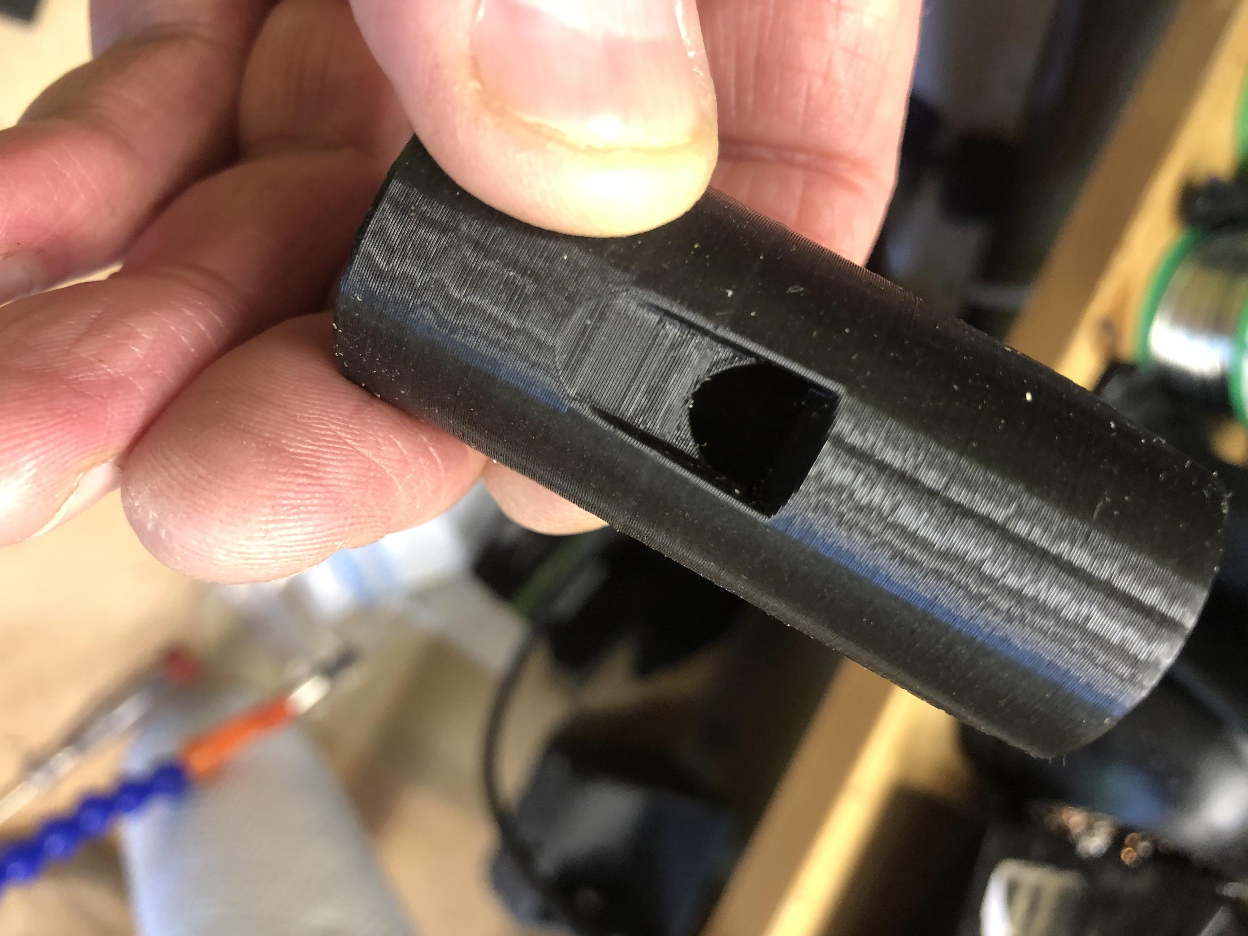
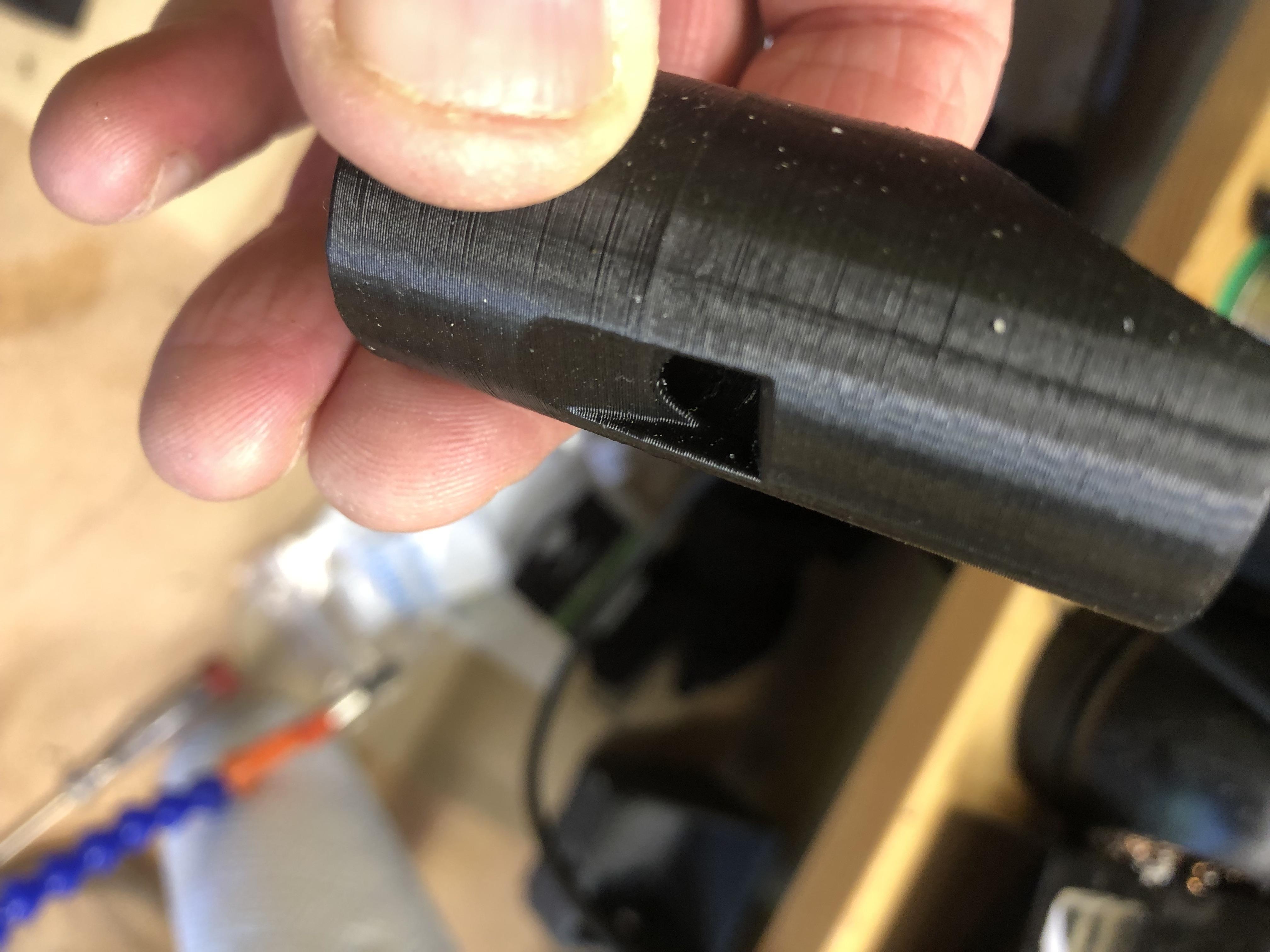
The next process was to split this body using the Fit Point line we just created and to do this we need to go into the modify tab and select the body in our design for the cutting tool we select the line, and this in turn splits the body, it doesn't look as though anything has happened but look in the left hand column and there is an additional body, using the eye on the associated body tab just deselect the one we no longer want and delete it and that leaves us with our recorder mouthpiece shape, we now need to form then slot for the sound hole, there slots are tapered from the inside of the mouthpiece to the outer.
The only only way I could see to do this at the time was this.
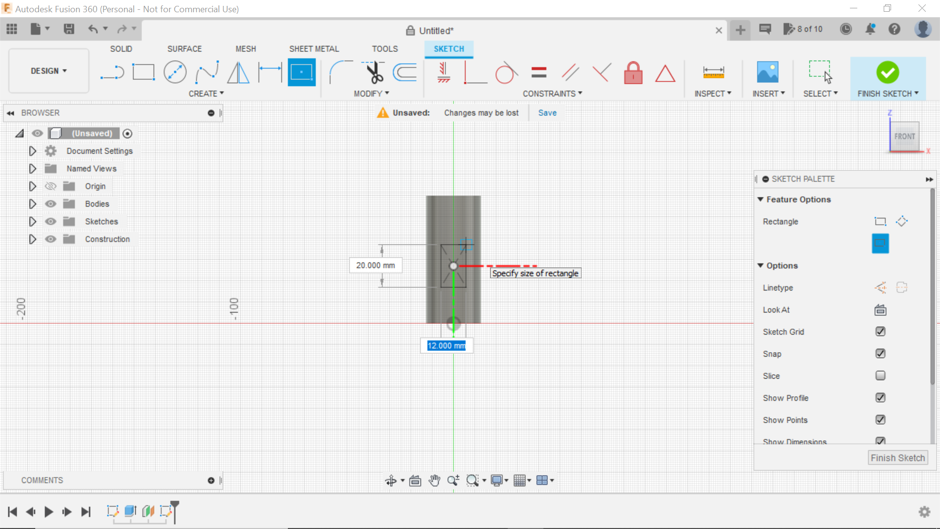
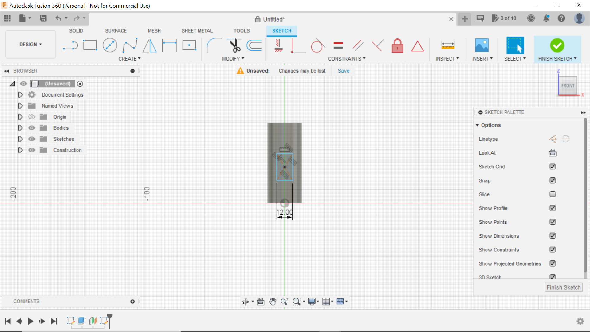
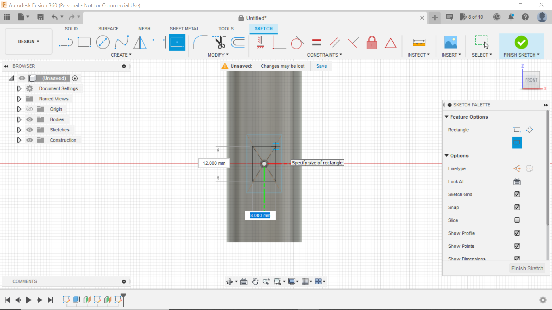
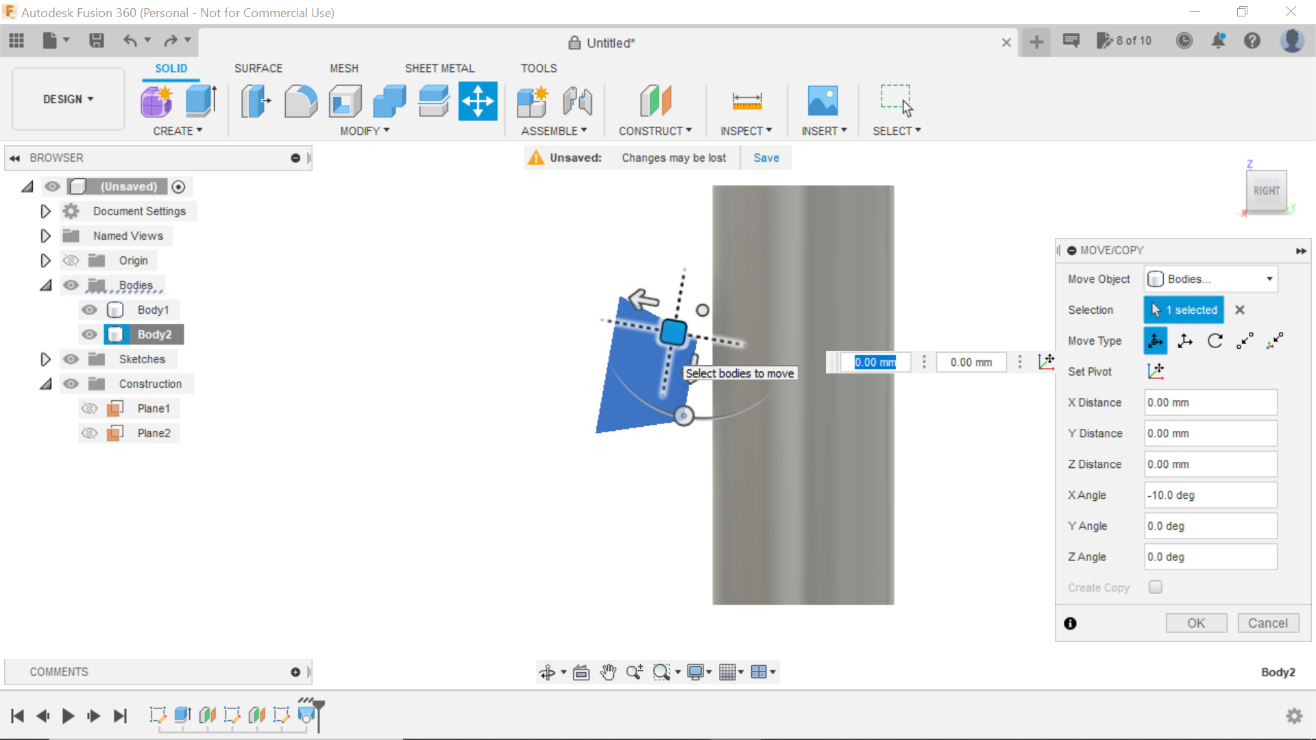
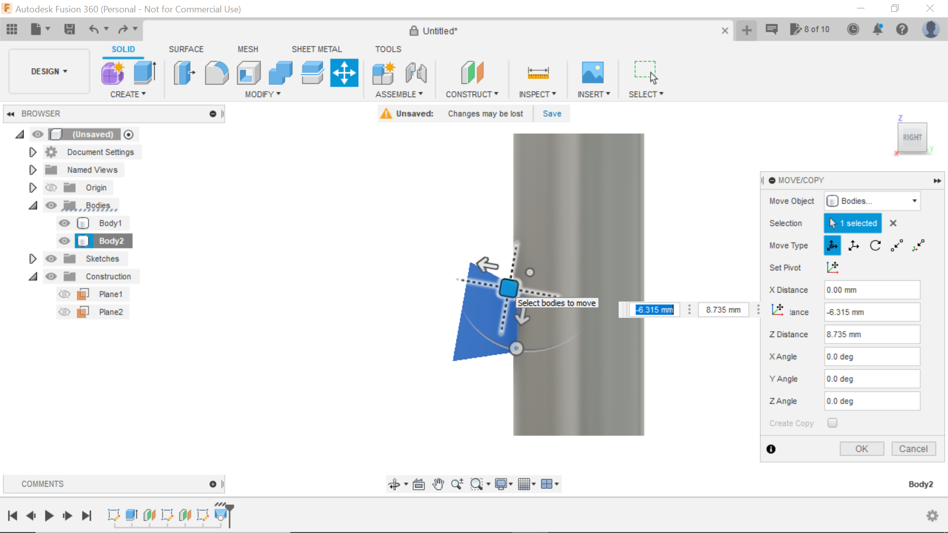
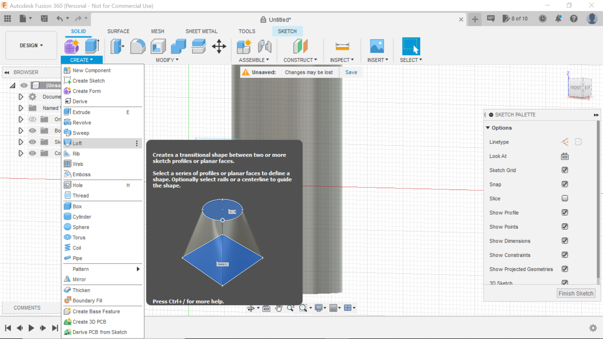
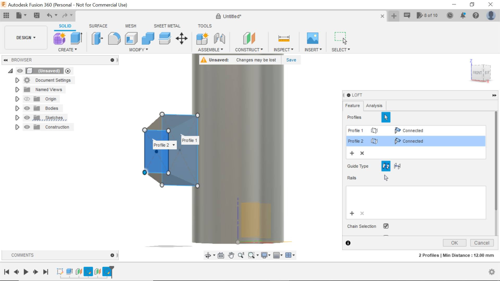
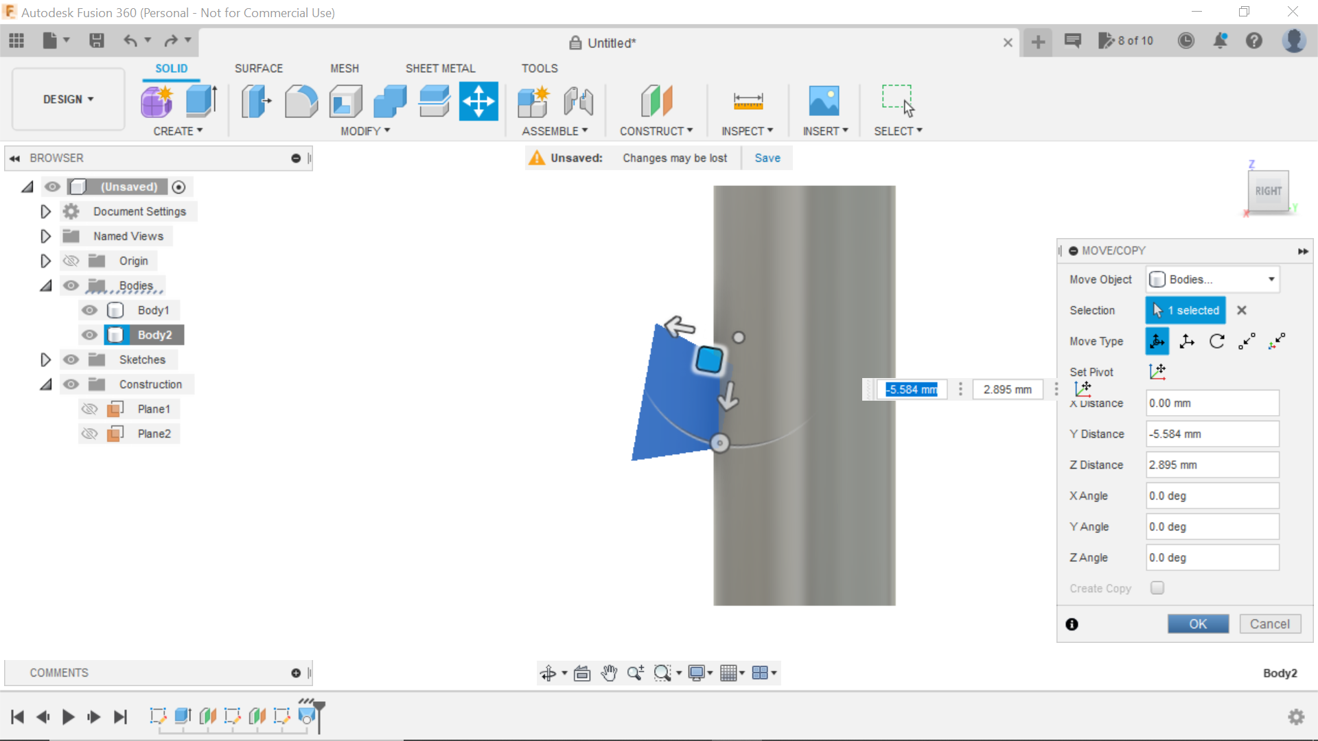
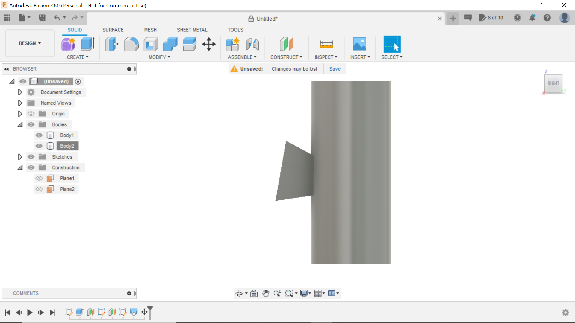
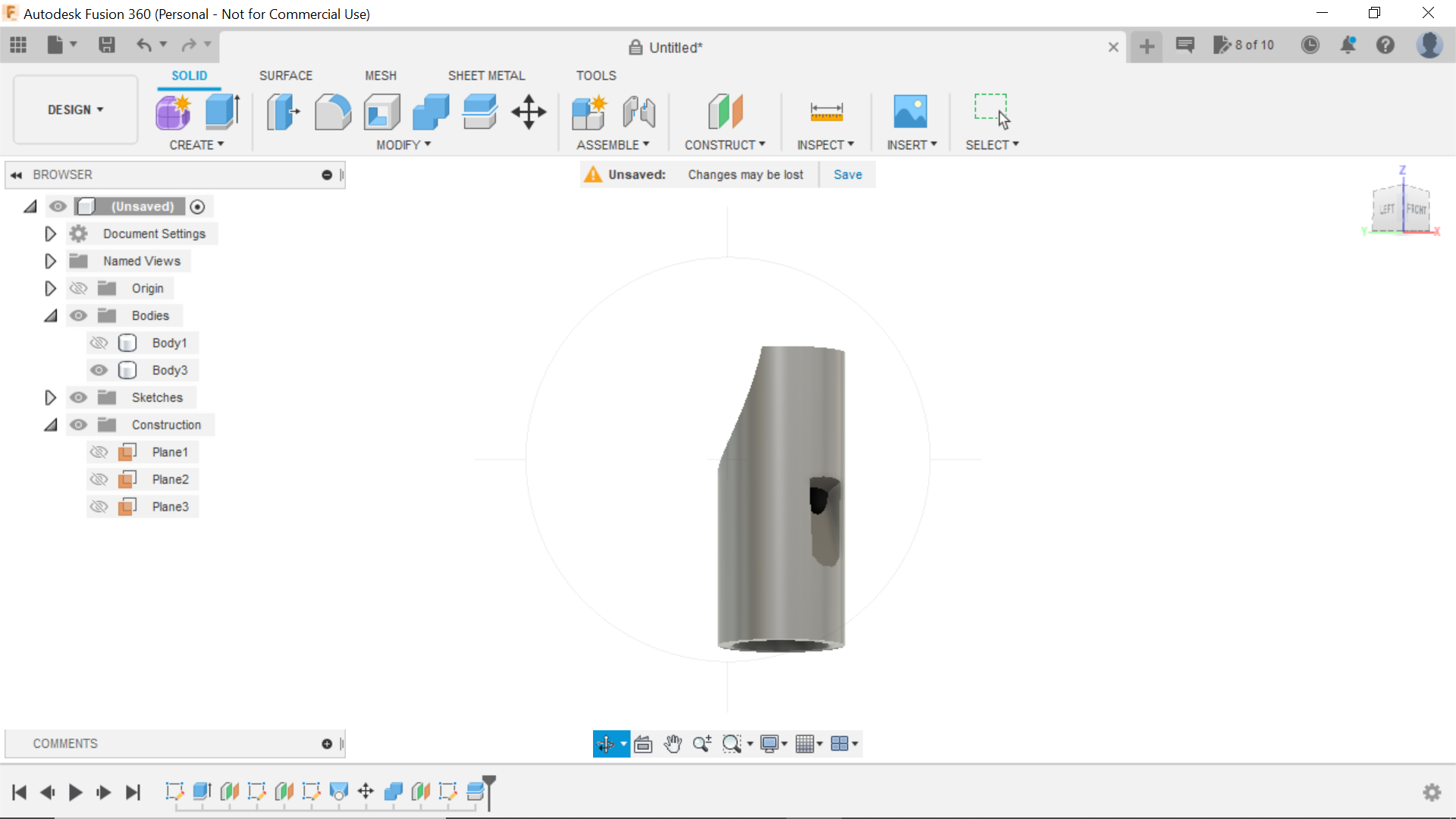
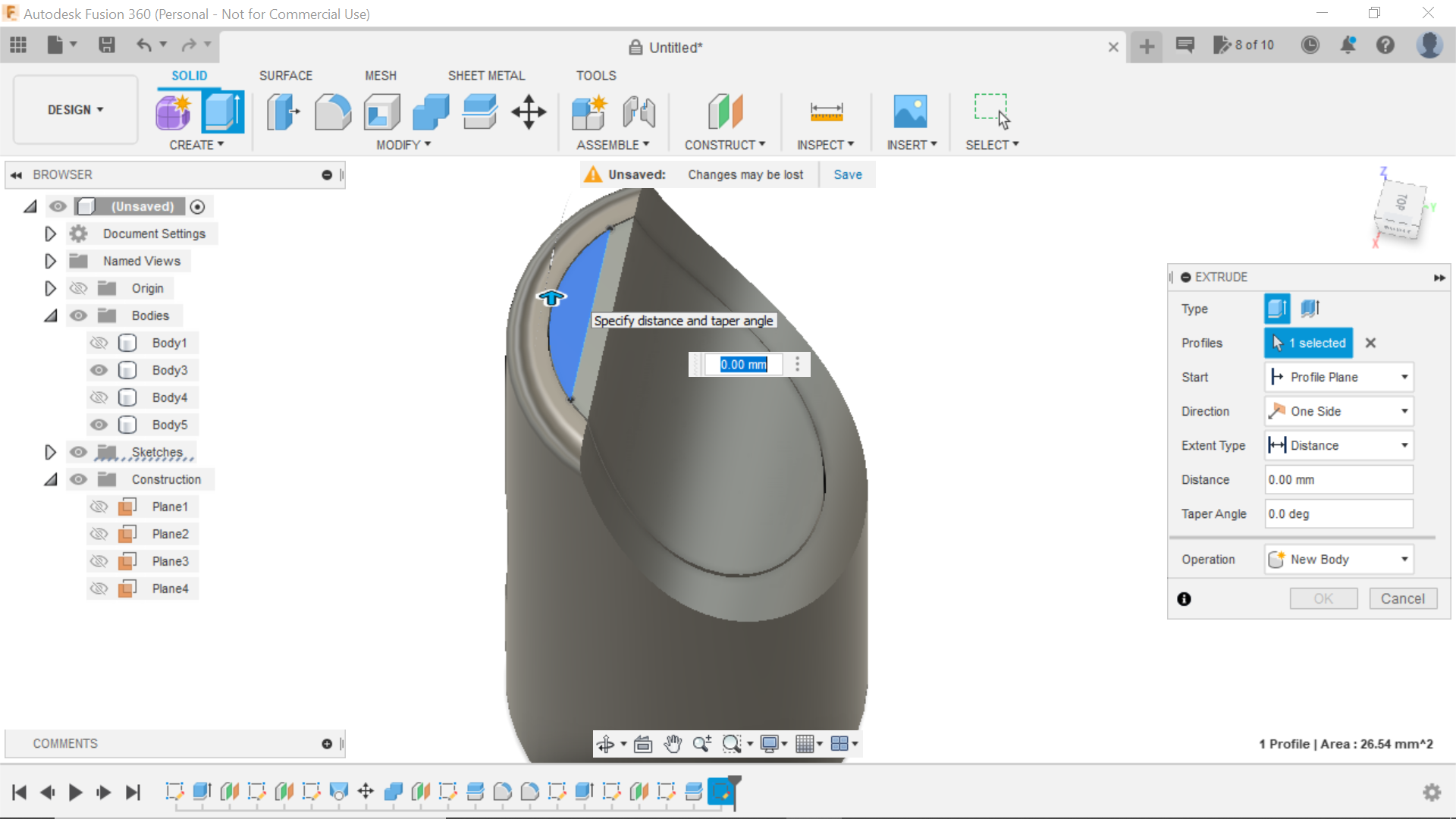
From a forward view of the mouthpiece, create offset plane from the centre plane and bring it out 30mm next create sketch and select that plane, the next part was just guesswork, using the centre rectangle tool I created a rectangle 20mm long x 12mm wide literally placed it where I thought the sound hole should be, I then finished sketch and using this rectangle created another offset plane at 15mm, I sketched onto this plane a smaller rectangle of 12mm x 8mm it looks as though its offset in the sketch but its 2 separate planes, from the Solid tab now select loft, and select one plane, then the other to create a wedge, this in turn creates a new body, right click on this body in the left hand column and click on copy/move, now turning the mouthpiece to a side view, use the handles to rotate the wedge 360degrees and then angle it as in the screen shots and manoeuvre into the mouthpiece body, it should be flush at the surface but digs into the cavity of the mouthpiece, I had to play with this for a while, and when you are happy, click on ok.
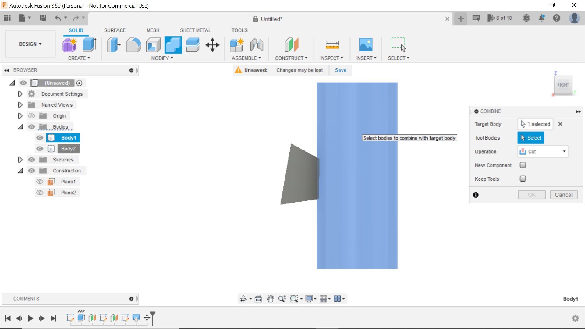
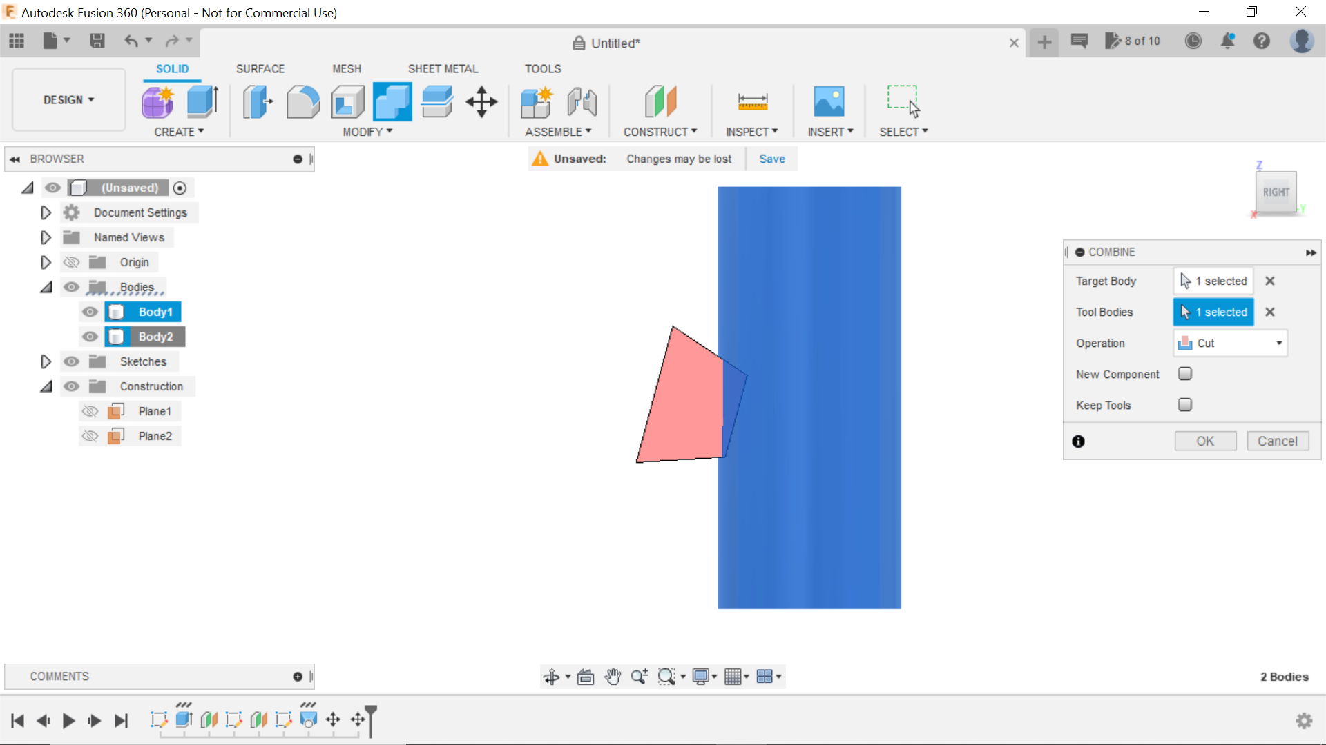
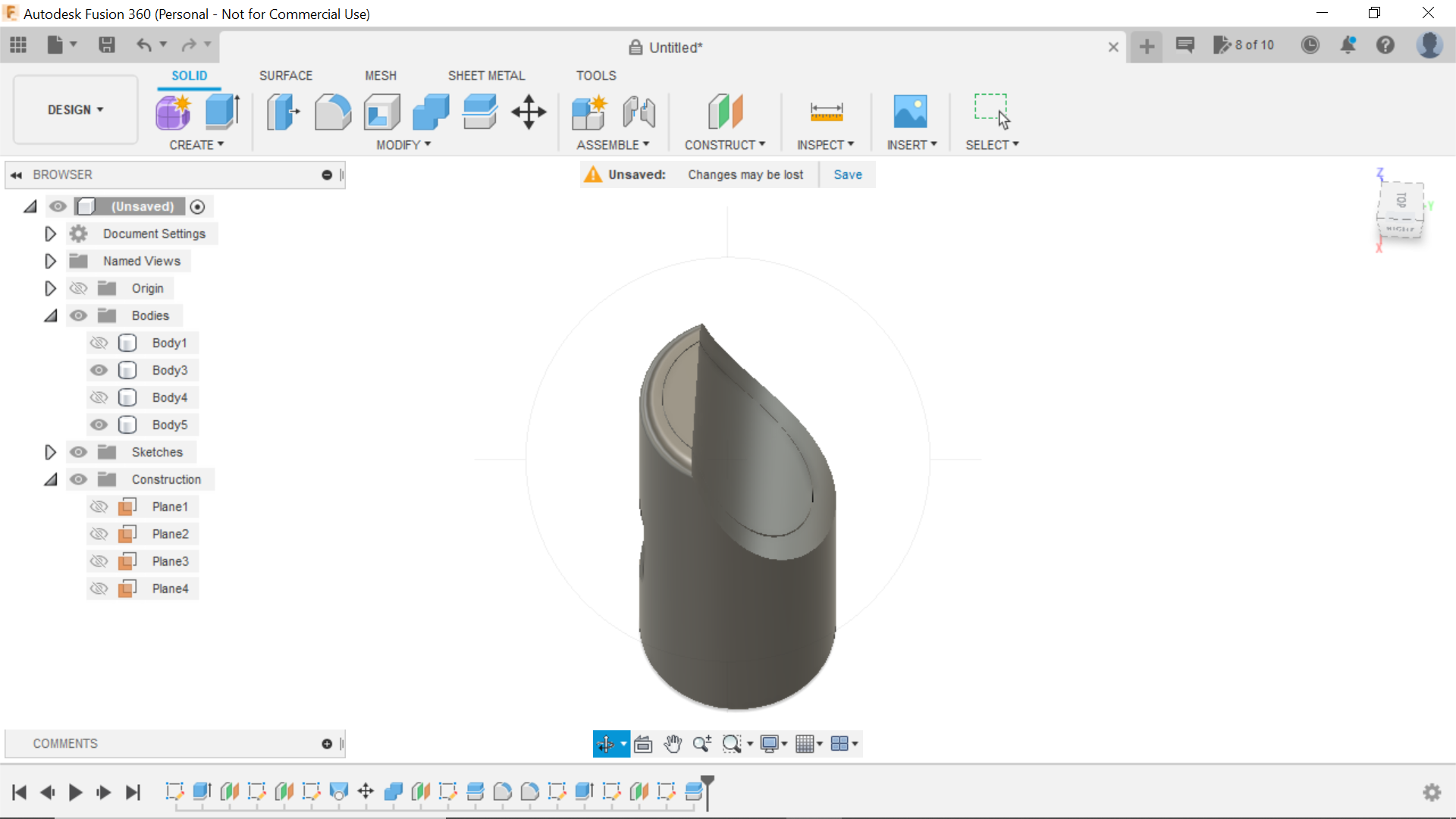
We now have to separate bodies, the mouthpiece and the wedge, we need to cut the body with the wedge, so using the combine tab, we select the mouthpiece as the body to be cut, and the wedge to cut it. then click ok, and finding the Wedge body and either turn it off or delete it, we now have our sound hole.
We can now move onto making our reed or whatever its called:
Creating the Reed for the Mouthpiece
.png)
.png)
.png)
.png)
.png)
.png)
.png)
.png)
.png)
.png)
.png)
.png)
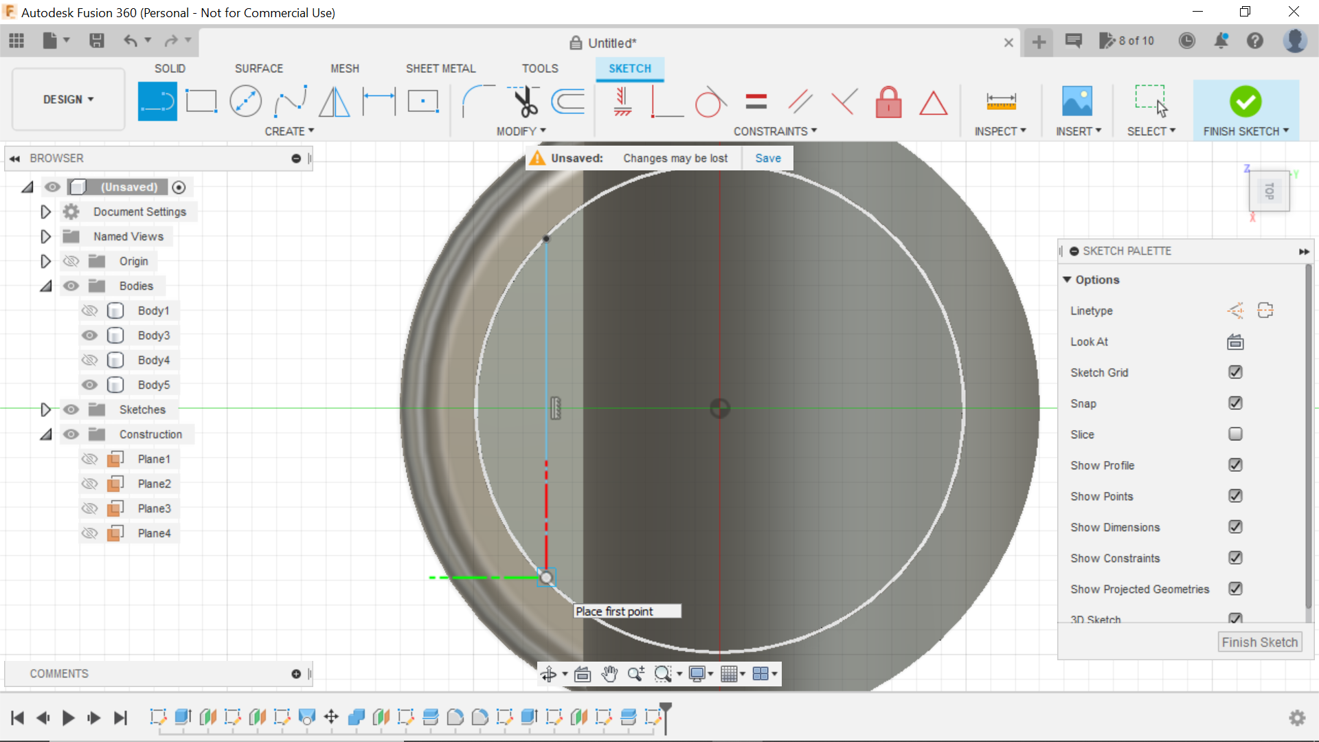
To achieve this part of the mouthpiece, I created a new sketch and chose the bottom face of the mouthpiece to sketch on, I then created a centre circle to the inside edge, I then extruded this so it was flush with the end of the mouthpiece and made it a separate body, then selecting the bottom of the reed I extruded that into the mouthpiece giving enough room for the conduit to be pushed in, end sketch.
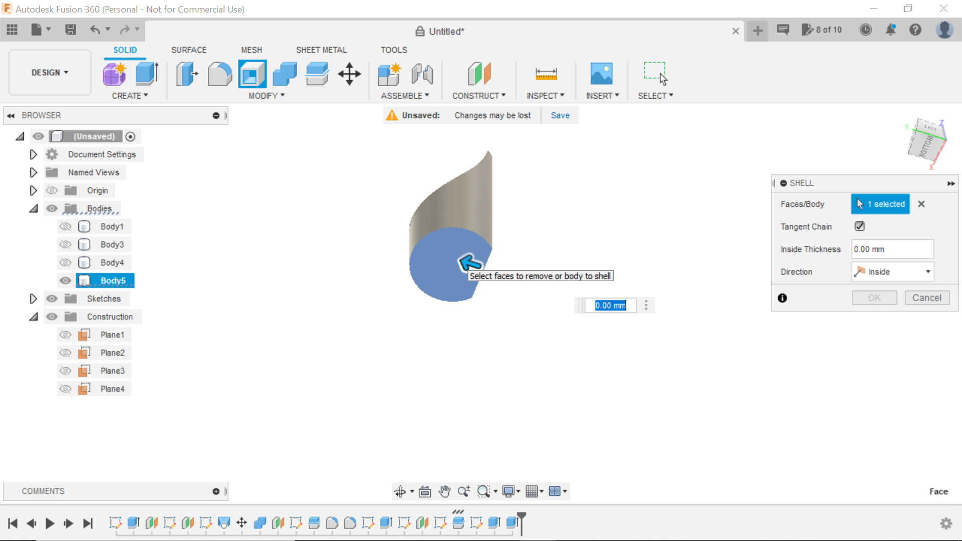
We now need a side view of the mouthpiece and create another offset plane from the centre and bring the plane out 30mm then sketching from that plane use the fit point spline tool to follow the existing contour of the mouthpiece, we then do the same as with the mouthpiece and use the line to split the body, we now need to create a channel on top of the reed for the wind to travel through, to do this I created a new sketch and selected the top end of the reed, and guessed where the line should be to create the gap, I then extruded the gap through the piece to give us an airway, the final thing to do was using the bottom of the reed, I used the shell tool to hollow it out to 2mm.
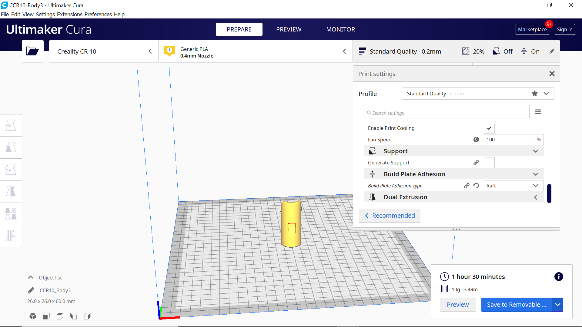
We now have two separate components to 3D print.
Final Steps
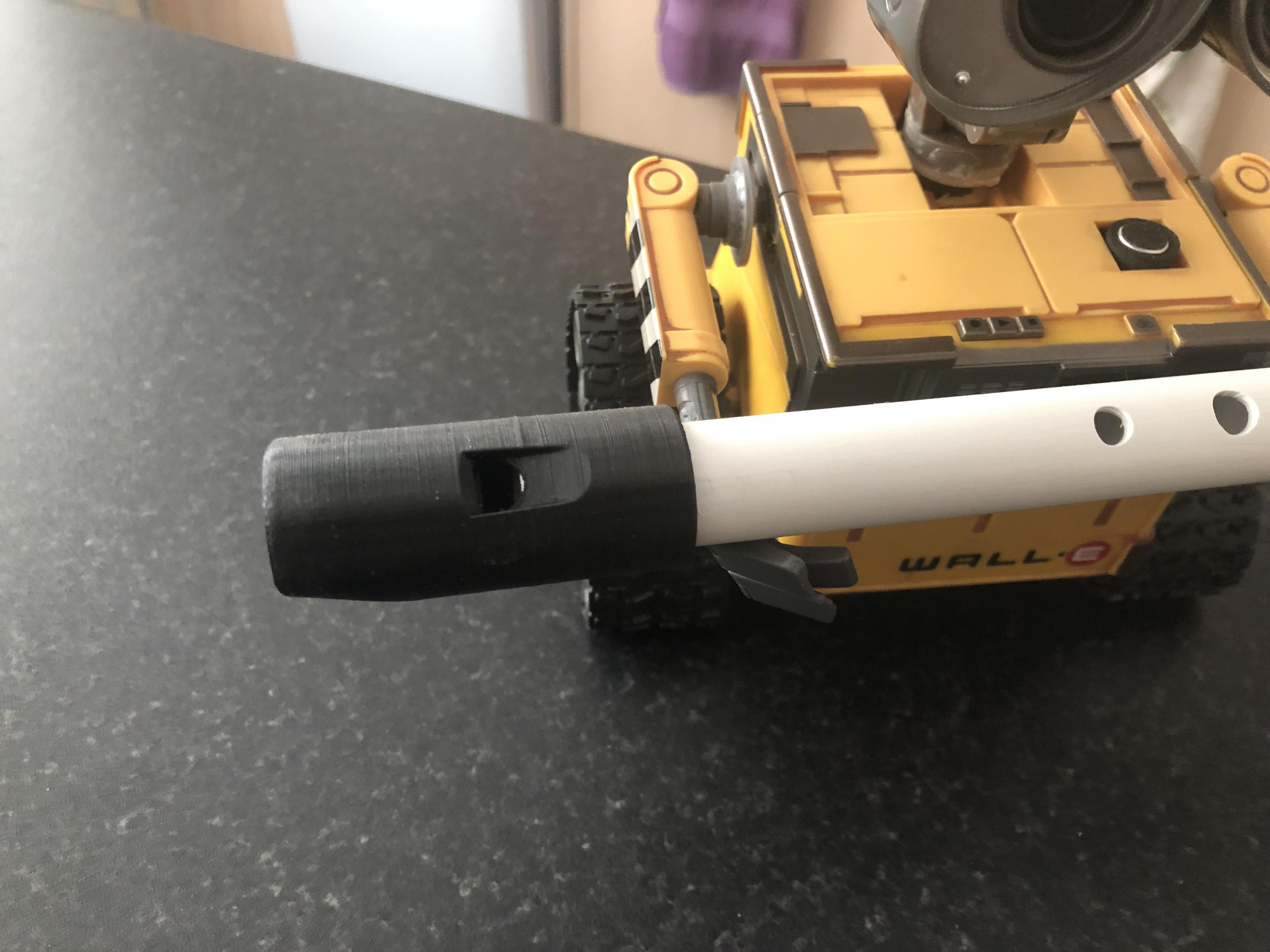
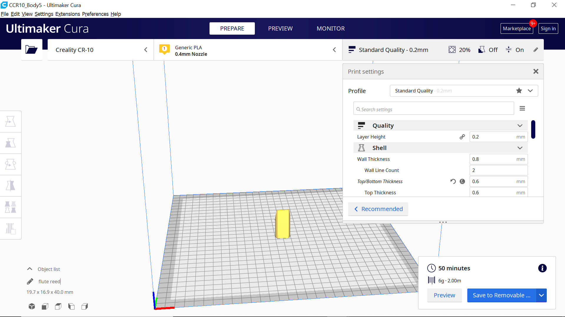
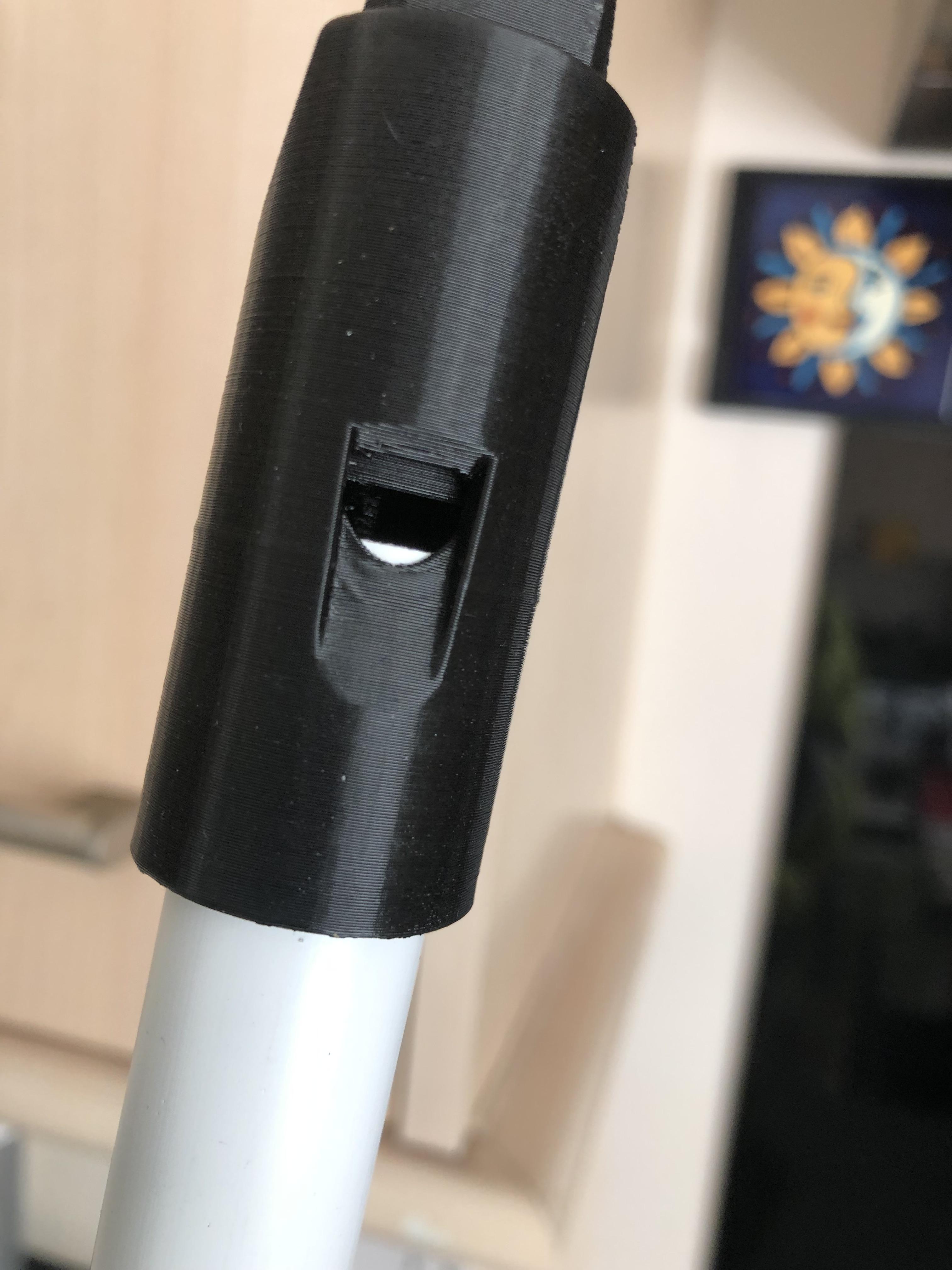
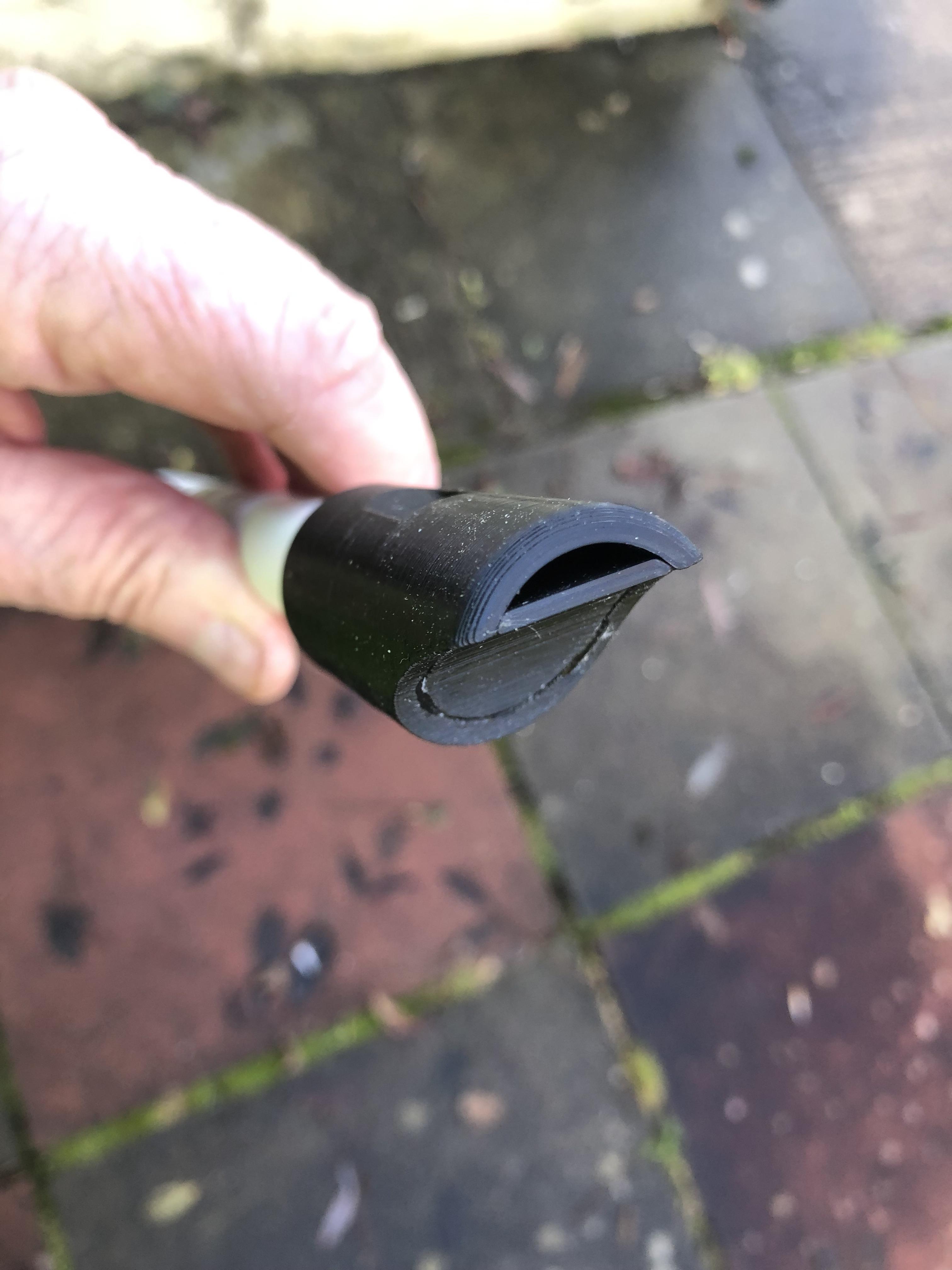
With the mouthpiece and reed printed we can now push the reed into the mouthpiece, Insert the conduit and see if we can get a note out out of it, with no fingers on the holes it should play a constant tone, I ended up cutting more off the bottom part of the reed allowing the conduit to push in further until I had a satisfying note, I could then glue the reed into position.
There you have it, a diy 20mm plastic conduit tin whistle esk type of instrument, the mouthpiece is really comfortable when playing and the notes are all there, and with 3 fingers over the first 3 holes this note is a G and going on line and getting a Constant G Drone note it was in tune, which amazed me really, I didn't have all the correct diameter drill bits for this project, but the notes are pretty close and after all its just a bit of fun, but also utilising 2 or 3 good disciplines in Fusion 360.
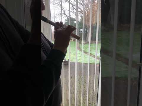
I apologise for the tune on the short video, I've never played Tin Whistle before but wanted to demonstrate a little and let people hear it in action unfortunately I had tested positive for covid at the time of the build as well which also meant I was a bit short of wind to blow the thing, I'd also like to re-assure you that you wont find me busking anytime in the near future in a city near you:))
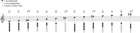
The screen shot shows the notes associated with a "D" Tin Whistle and where to place your fingers over the holes.
Hope you enjoy the Instructable and it gives you some good ideas, and thanks for looking.