Concentric Rings Fidget Toy
by voidbubble in Workshop > 3D Printing
4404 Views, 56 Favorites, 0 Comments
Concentric Rings Fidget Toy
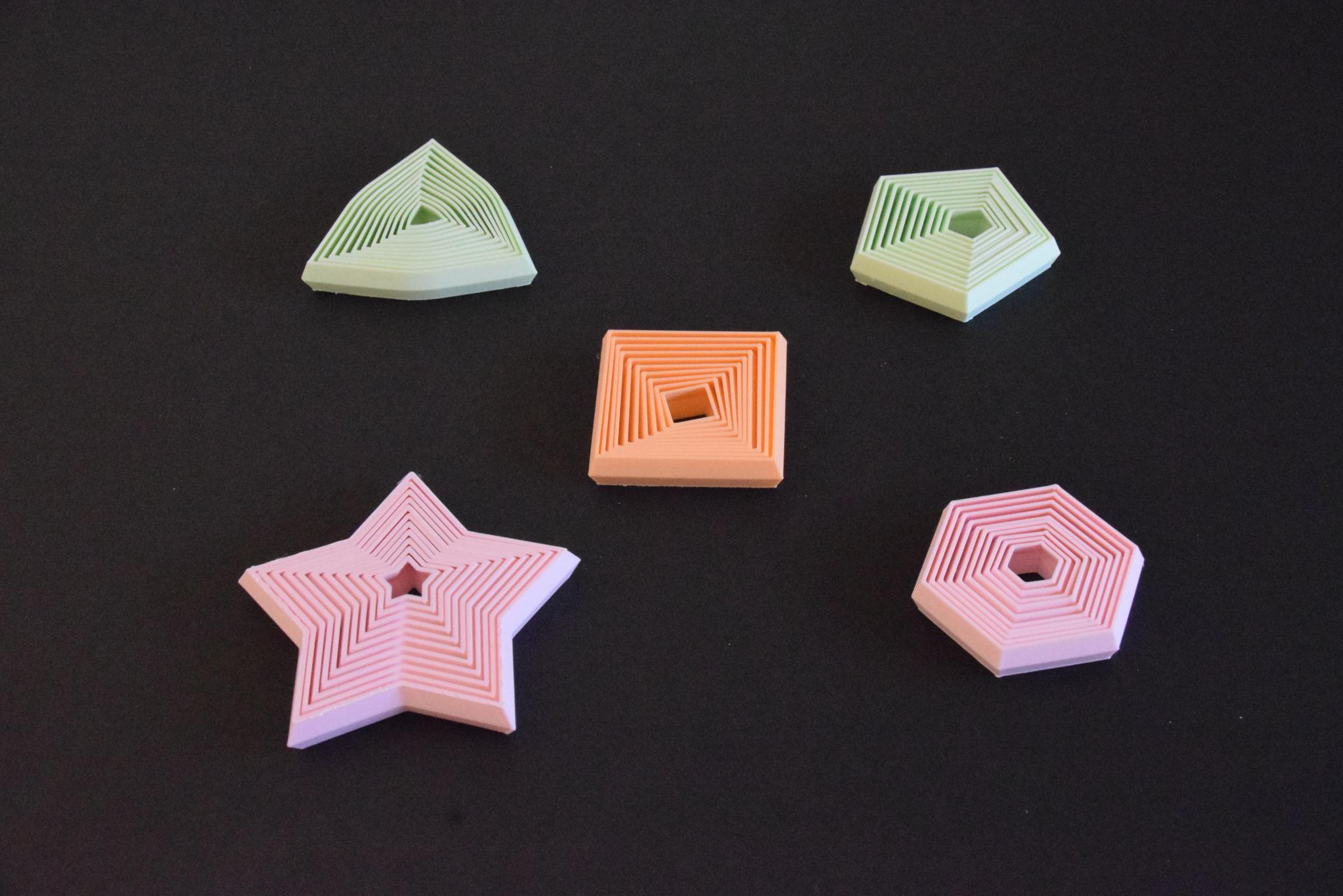
A collection of small fidget toys consisting of concentric rings with instructions on how to make your own in Fusion 360. They are inspired by this fidget toy:
This design is appealing both for the patterns and sounds it makes when moving the rings around, as well as for being uniquely tailored to an FDM printer's method of manufacturing. The rings taper at both ends and are spaced so that they have a little free movement without the assembly coming apart. We can easily implement this concept in Fusion 360 and quickly experiment and iterate on the design using parametric modeling (a toy using the method below is provided).
Downloads
Design Principle and Parameter Setup
This toy consists of concentric rings stretched in the middle, so each ring moves without falling off. Since it is symmetric, we only need to construct the bottom half. We will do this as a series of concentric rings on the xy plane, extrude them at half the toy height while applying a taper, and mirror the result with respect to a plane placed at half the toy height. Determining the optimal distance between two consecutive rings requires some experimentation but can be done quickly thanks to parametric design: we design two full consecutive rings, move the inner one upwards, inspect whether it intersects with the outer one, and adjust the relevant parameter until we are happy with the amount of movement allowed. A set of parameters that work well and will produce a short print is provided.
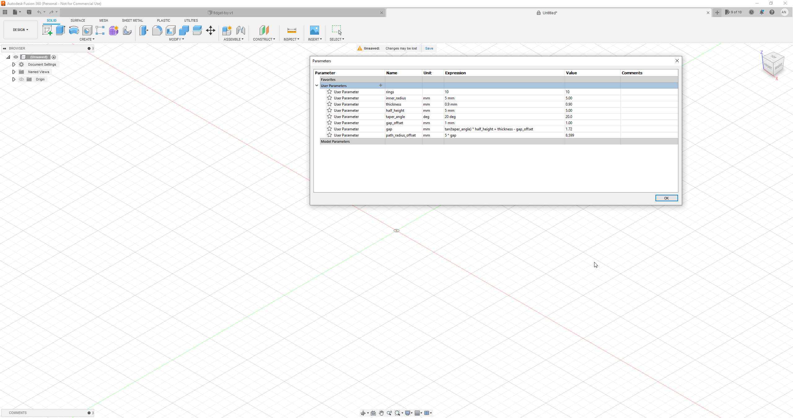
Let's create a document and add the following parameters by going to Modify > Change Parameters:
- name: rings, unit: no units, expression: <some integer>
The number of rings of our toy.
- name: inner_radius, unit: mm, expression: <some number>
The radius of the inscribed circle of the innermost polygon.
- name: thickness, unit: mm, expression: <some number>
The ring thickness. It should be thin enough to be printed in 2 or 3 walls without any infill. I used 0.9 mm for a 0.4 mm nozzle with a 0.45 mm line width.
- name: half_height, unit: mm, expression: <some number>
Half the height of our toy.
- name: taper_angle, unit: deg, expression: <some number around 15-20>
Ring taper angle.
- name: gap_offset, unit: mm, expression: <some number>
Determines the distance between two consecutive rings so that a ring can move without coming off the assembly.
- name: gap, unit: mm, expression: tan(taper_angle) * half_height + thickness - gap_offset
Distance between two consecutive rings.
- name: path_radius_offset, unit: mm, expression: 5 * gap
When the ring shape is a convex polygon, we construct the planar rings by sweeping lines around a polygon; for this method to work, we must place these polygon paths at several intervals. Intervals are different for different polygons, but placing a path every 5 rings is safe for pentagons and hexagons - if you encounter issues, try more frequent paths, or the manual offset method.
Planar Ring Construction
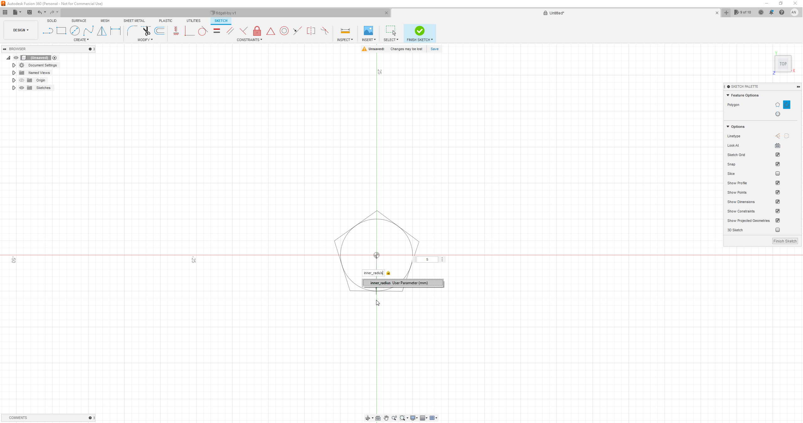
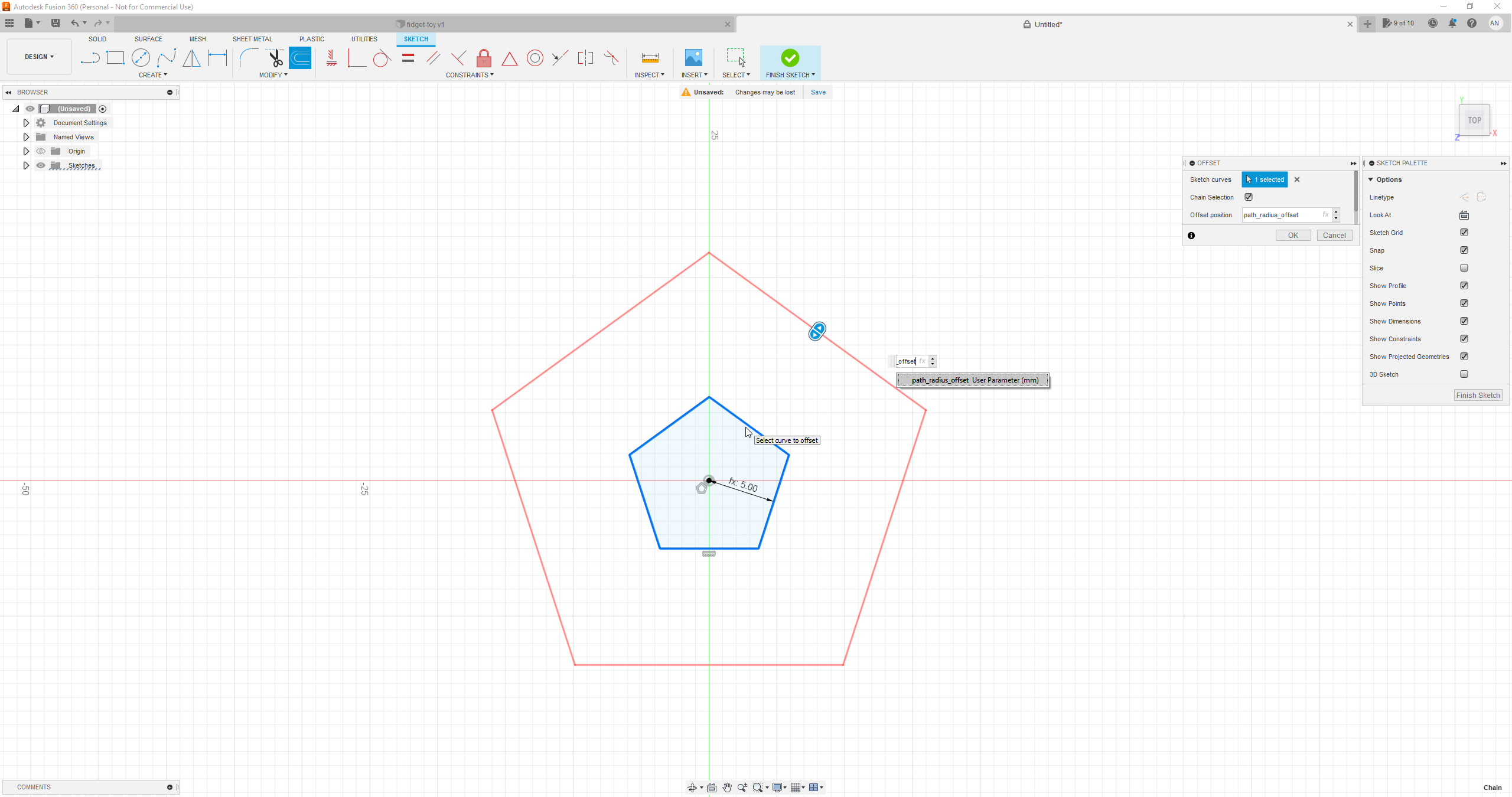
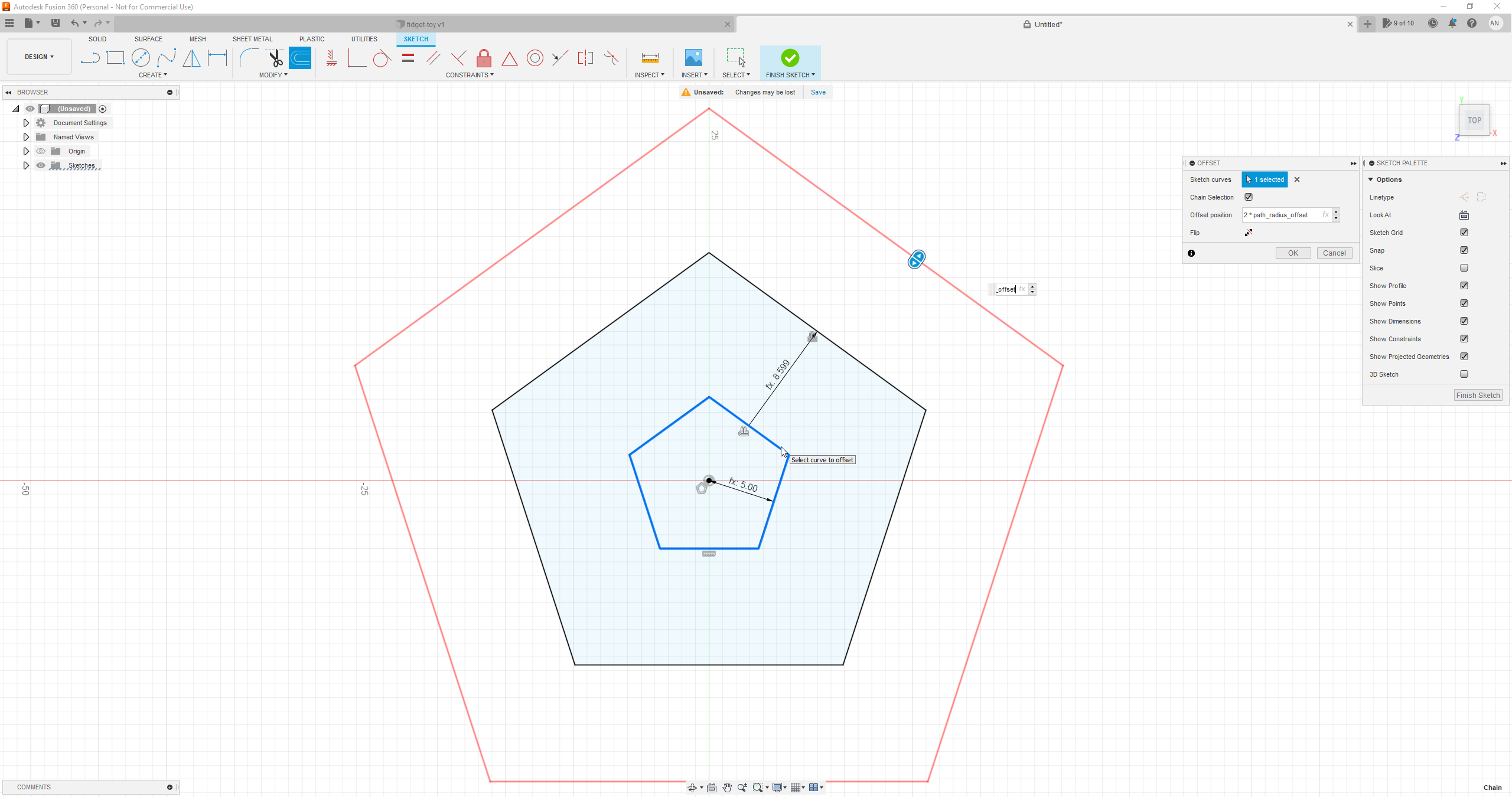
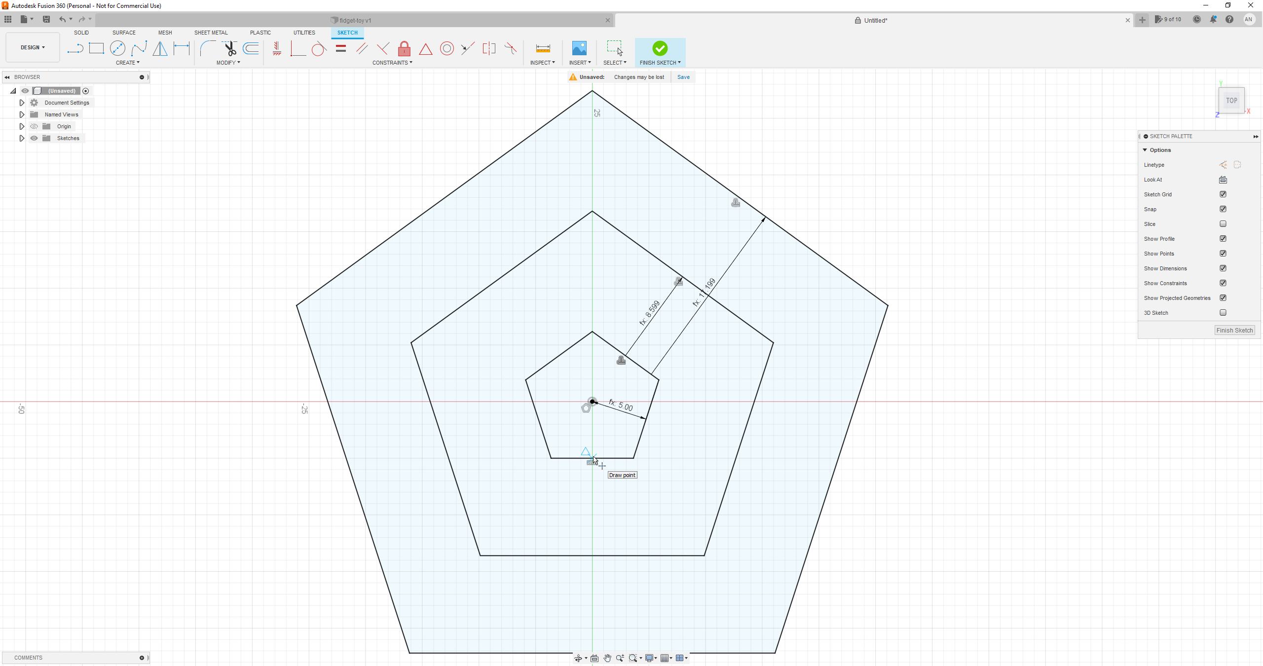
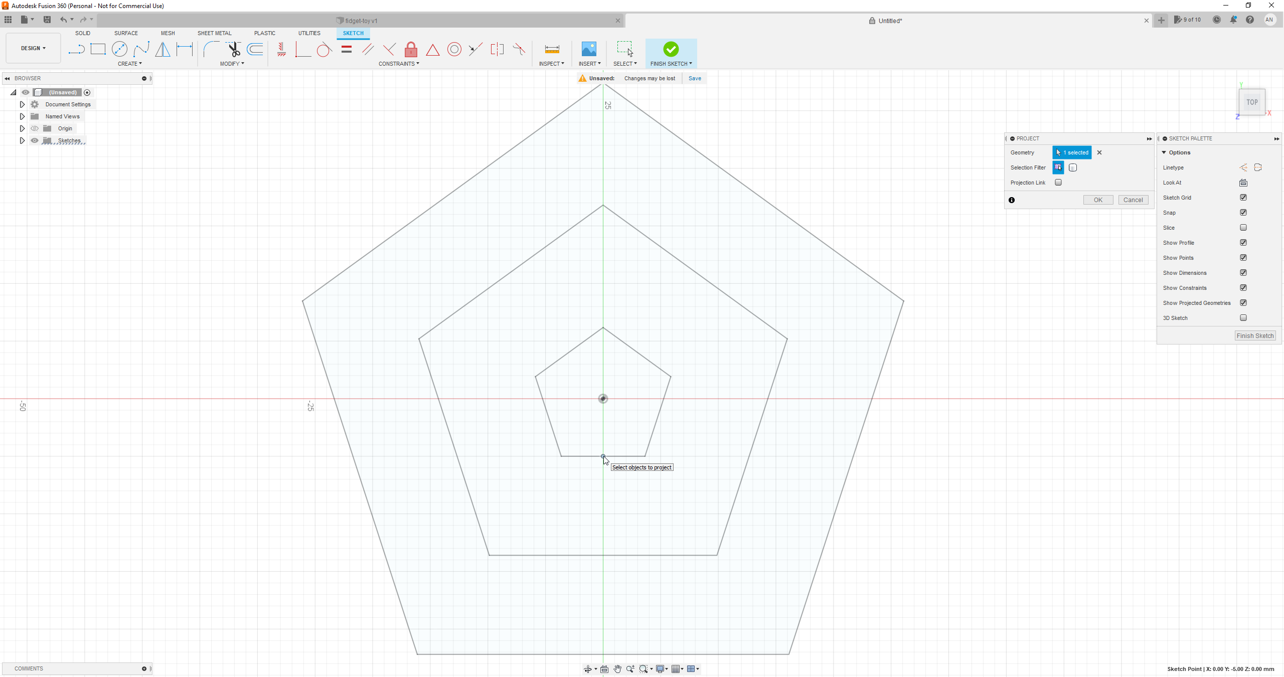
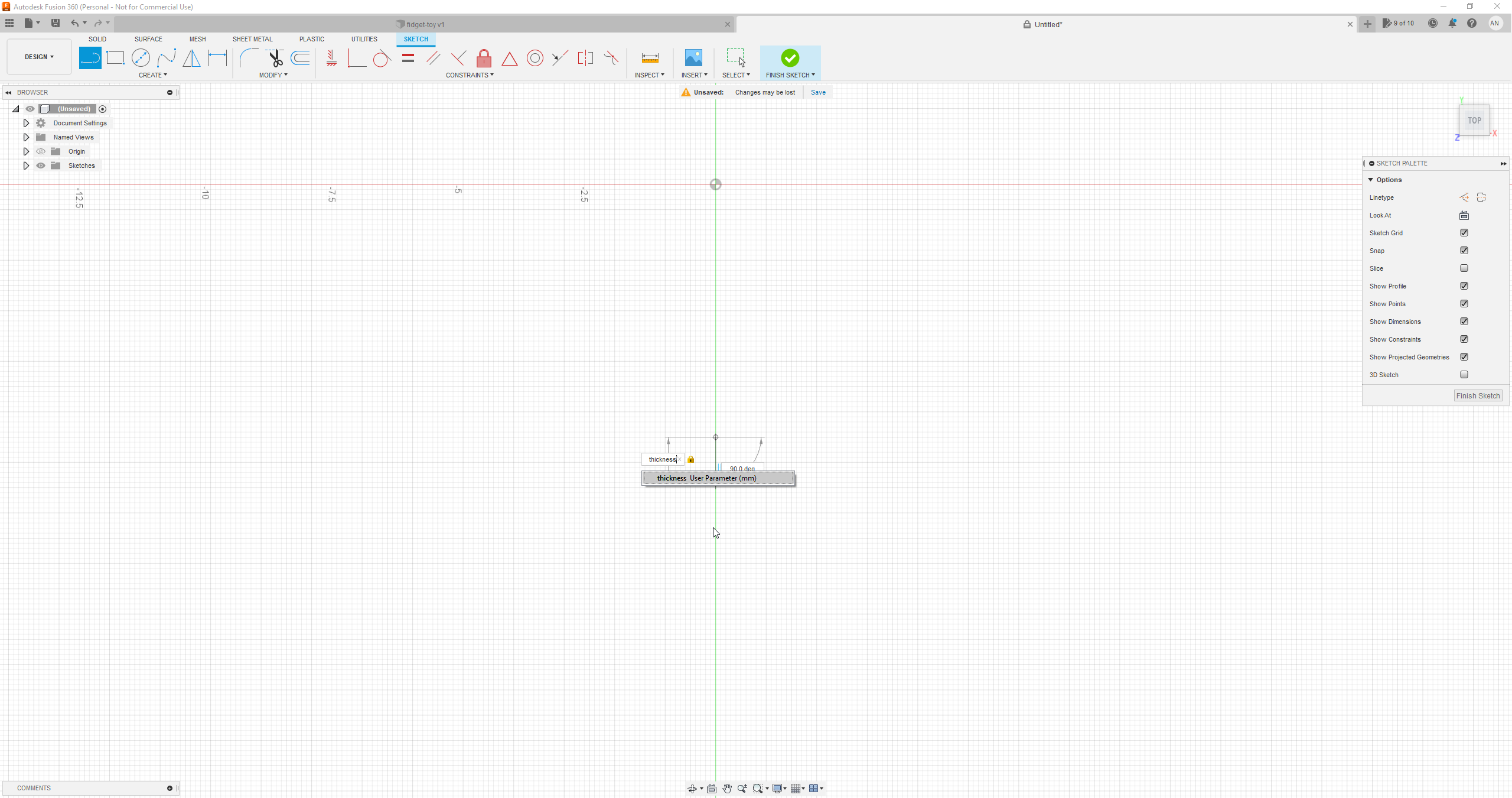
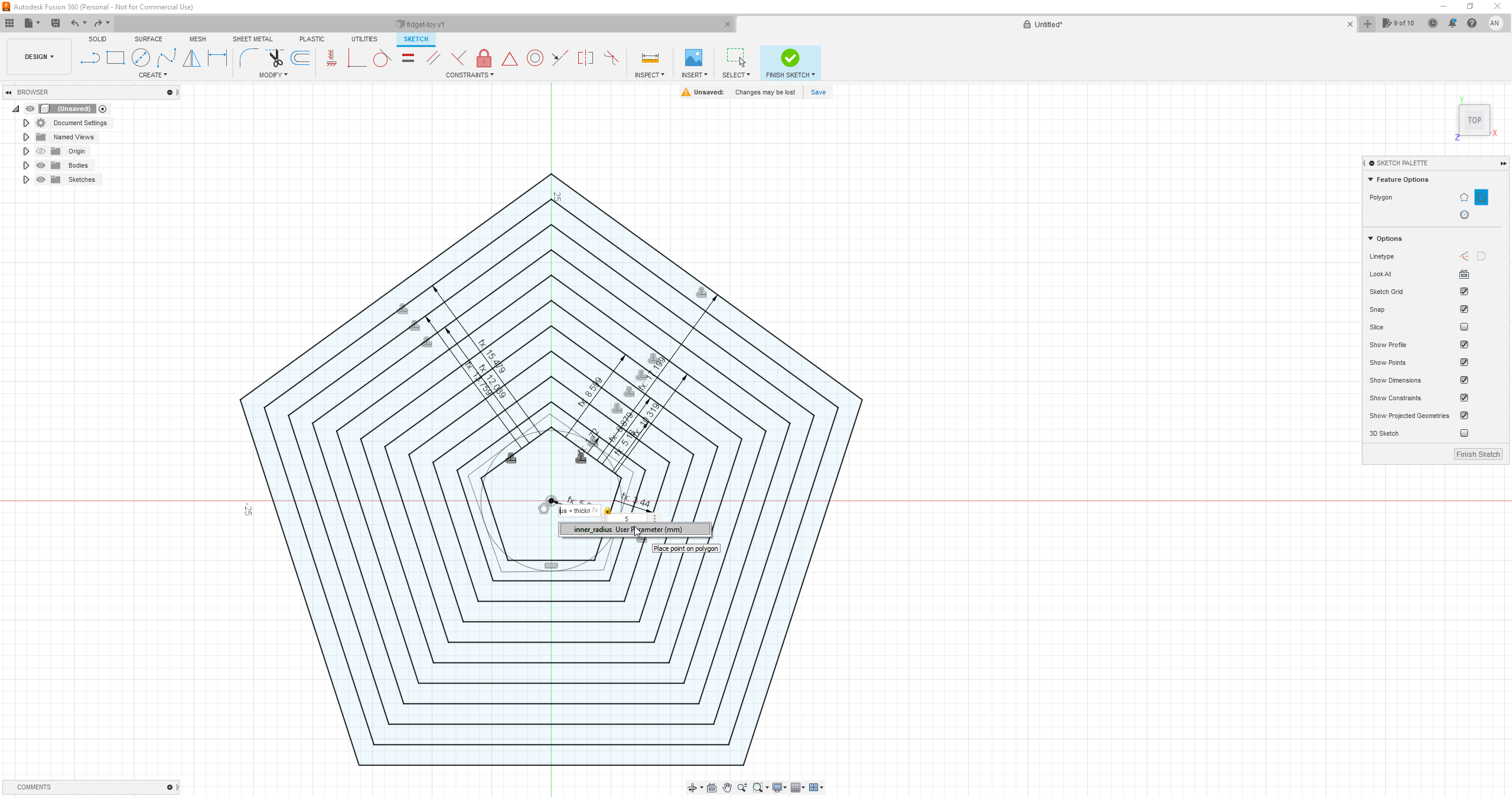
Start a sketch on the xy plane and create a circumbscribed polygon of radius inner_radius. Place a horizontal constraint on one of its sides. The next steps depend on the method for ring construction: sweep or manual offset.
2.1 Sweep
A fast method which works for some convex shapes without sharp corners.
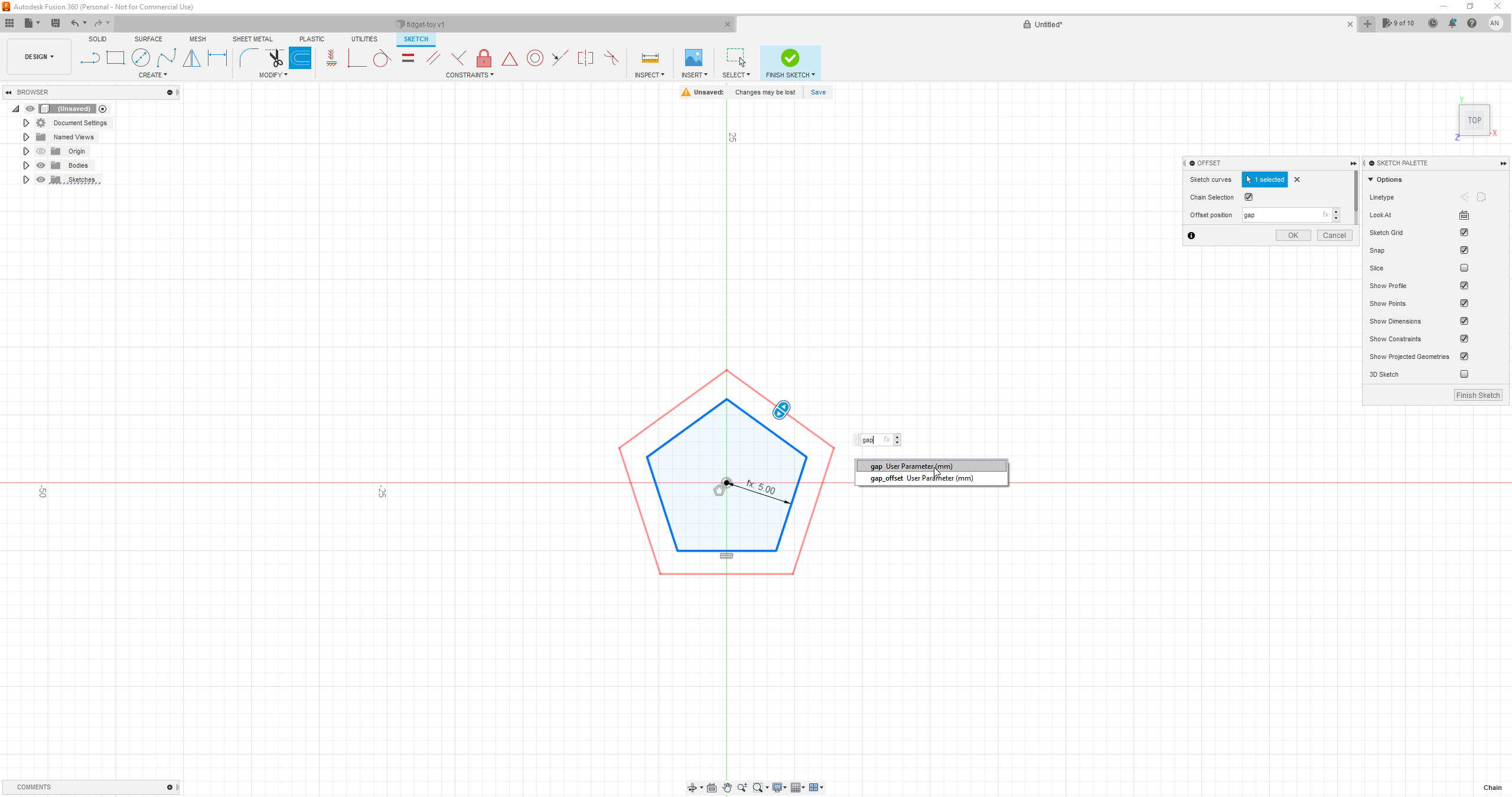
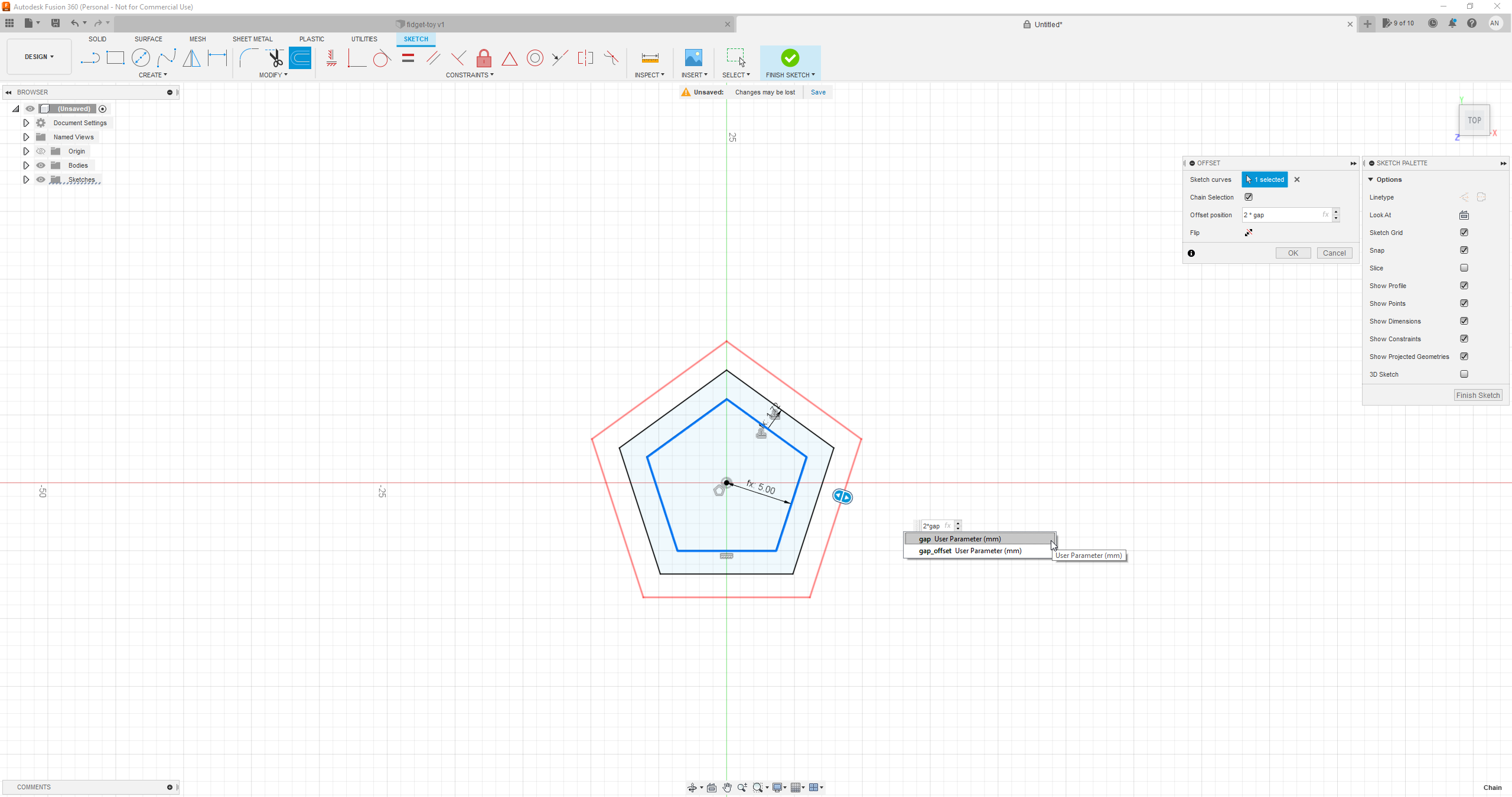
We first create the polygons to be used as sweep paths. Create additional concentric polygons by offseting the original polygon, so that all future rings are enclosed: for 10 rings, we offset the original polygon by path_radius_offset and by 2*path_radius_offset. Go to Modify > Offset and edit the following inputs:
- Sketch curves: select the polygon
- Offset position: path_radius_offset
Repeat as many times as needed by increasing the offset accordingly.
Go to Create > Point and create a point at the midpoint of the original polygon's horizontal side. Now finish the sketch.
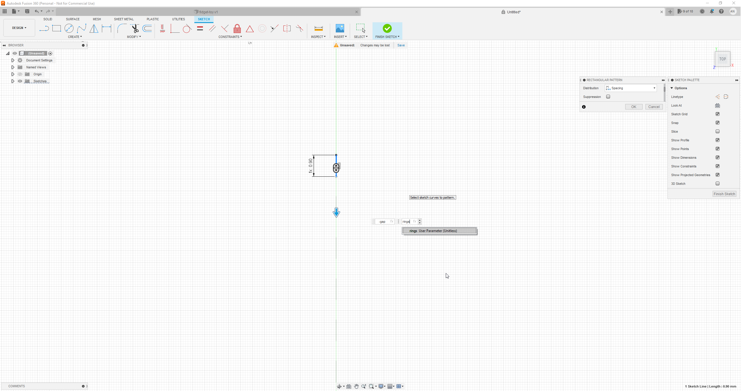
Now we create the lines to sweep. Start a new sketch on the xy plane and go to Create > Project / Include > Project and select the point we just created. Create a vertical line of length thickness starting from that point. Then, go to Create > Rectangular Pattern and edit the following inputs:
- Objects: select the line we just created
- Distribution: select Spacing from the menu
- x direction: Quantity: 1, Distance: 0.00
- y direction: Quantity: type rings, Distance: type -gap
Now finish the sketch.
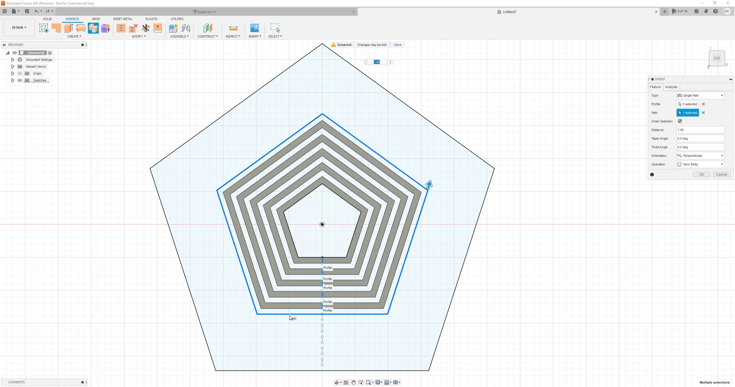
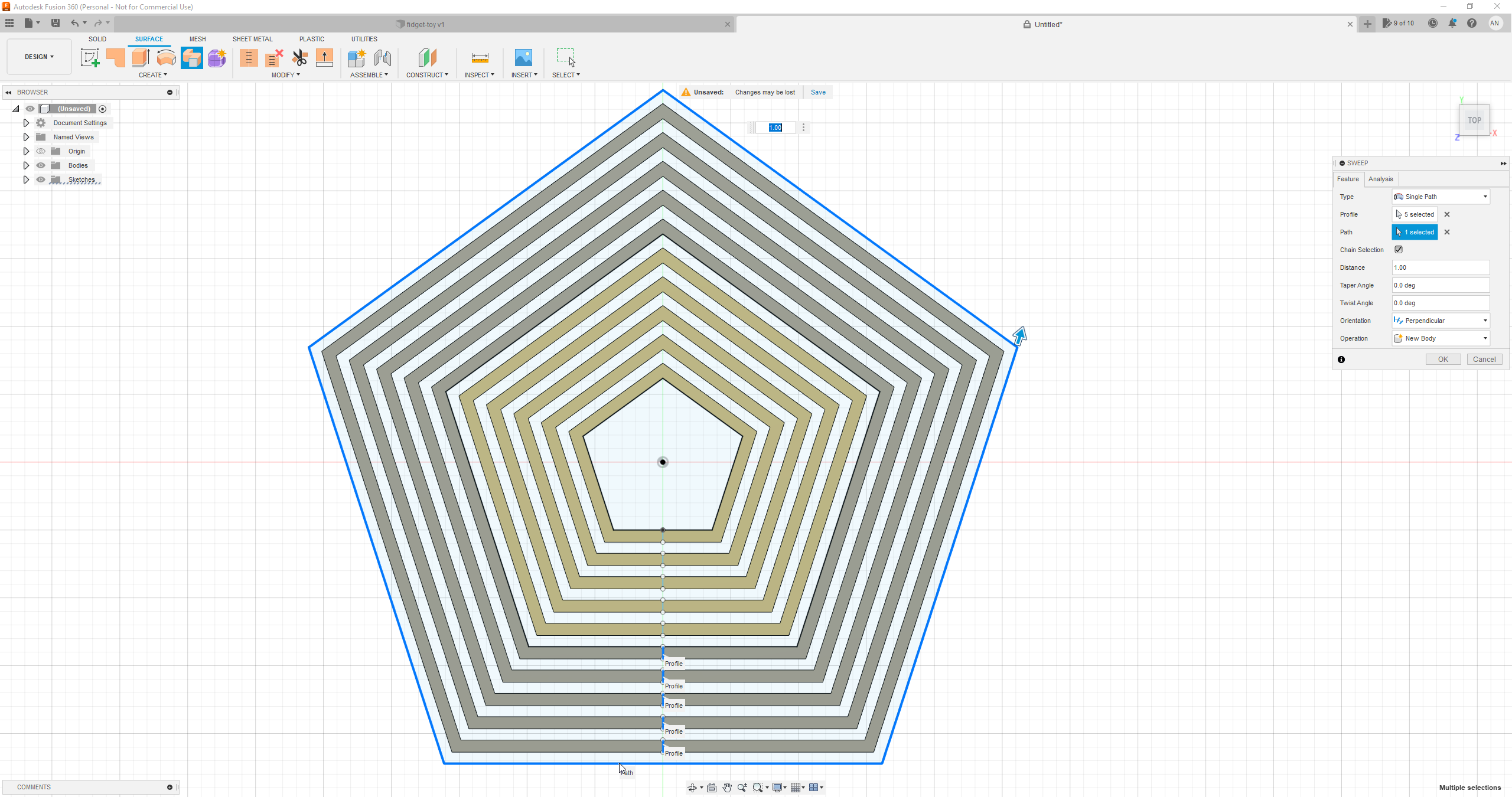
On the Surface tab, go to Create > Sweep and edit the following inputs:
- Profile: select the five innermost lines
- Path: select the innermost path polygon (the first offset polygon) by clicking on its horizontal side.
Repeat for the next batch of 5 lines and their enclosing polygon, and so on.
2.2 Manual offset
This is a somewhat slow method, as it requires manual steps, but it works for arbitrary shapes. We create the planar ring profiles by manually offseting two polygons. First, we create all inner walls. Go to Modify > Offset and edit the following inputs:
- Sketch curves: select the polygon
- Offset position: type gap
Repeat by selecting the original polygon and increasing the Offset Position by 2*gap, 3*gap and so on, until the desired number of rings is reached (n * gap, where n is the number of rings).
Now let's construct the outer walls. Create a circumscribed polygon concentric to the original one with radius inner_radius+thickness and place a horizontal constraint on one of its sides. Offset this polygon by gap, 2*gap, and so on as above. Now finish the sketch.
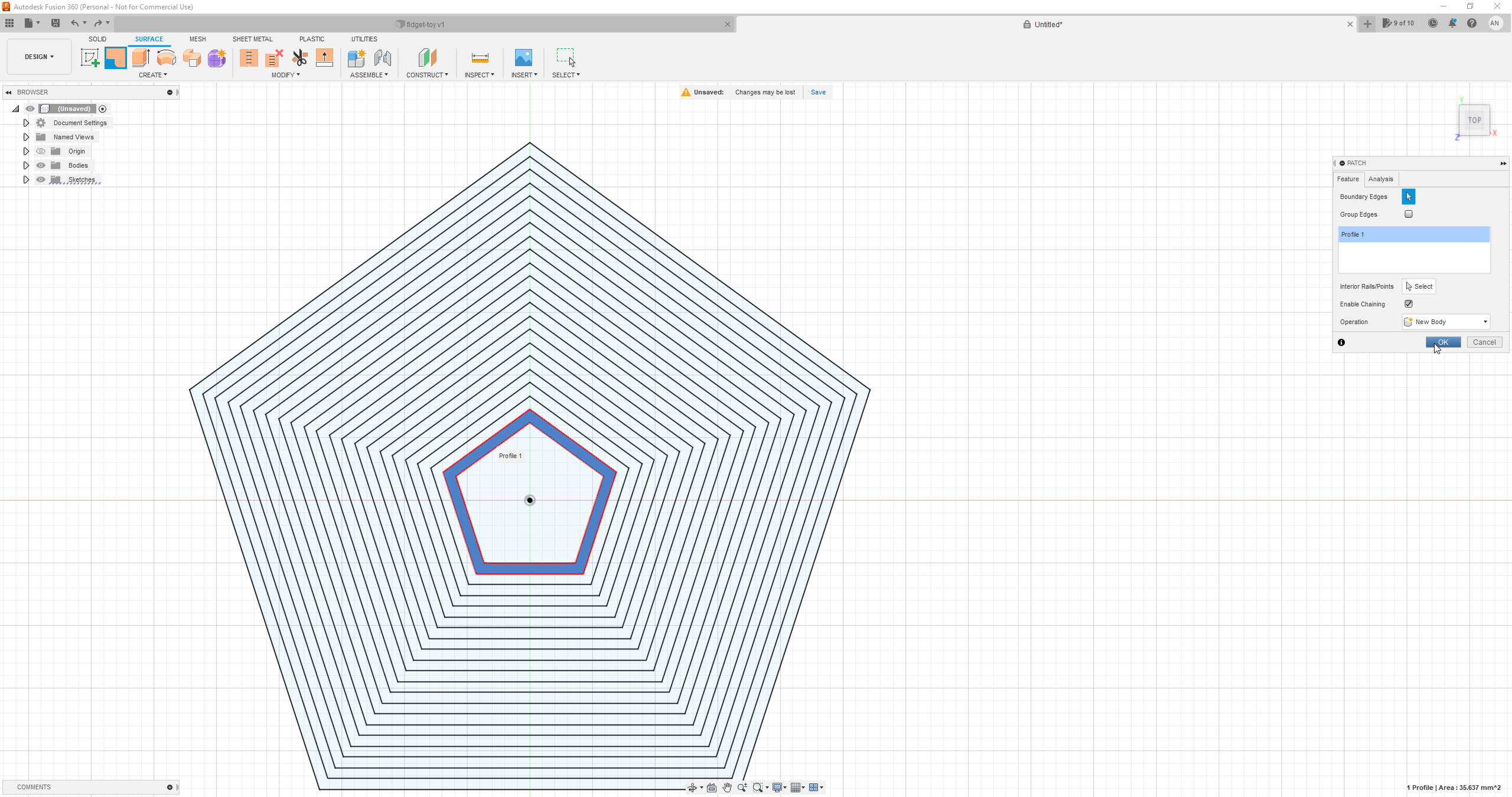
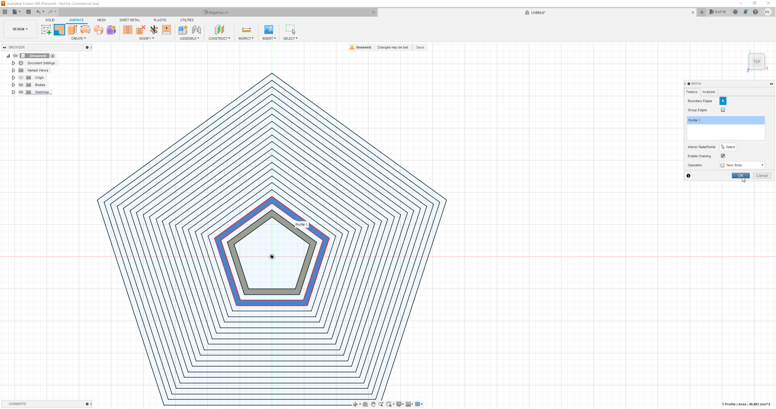
Now switch to the Surface tab. Click somewhere between the two innermost polygons, and go to Create > Patch and click OK. Repeat for the next set of rings, then the next, and so on.
Ring Extrusion
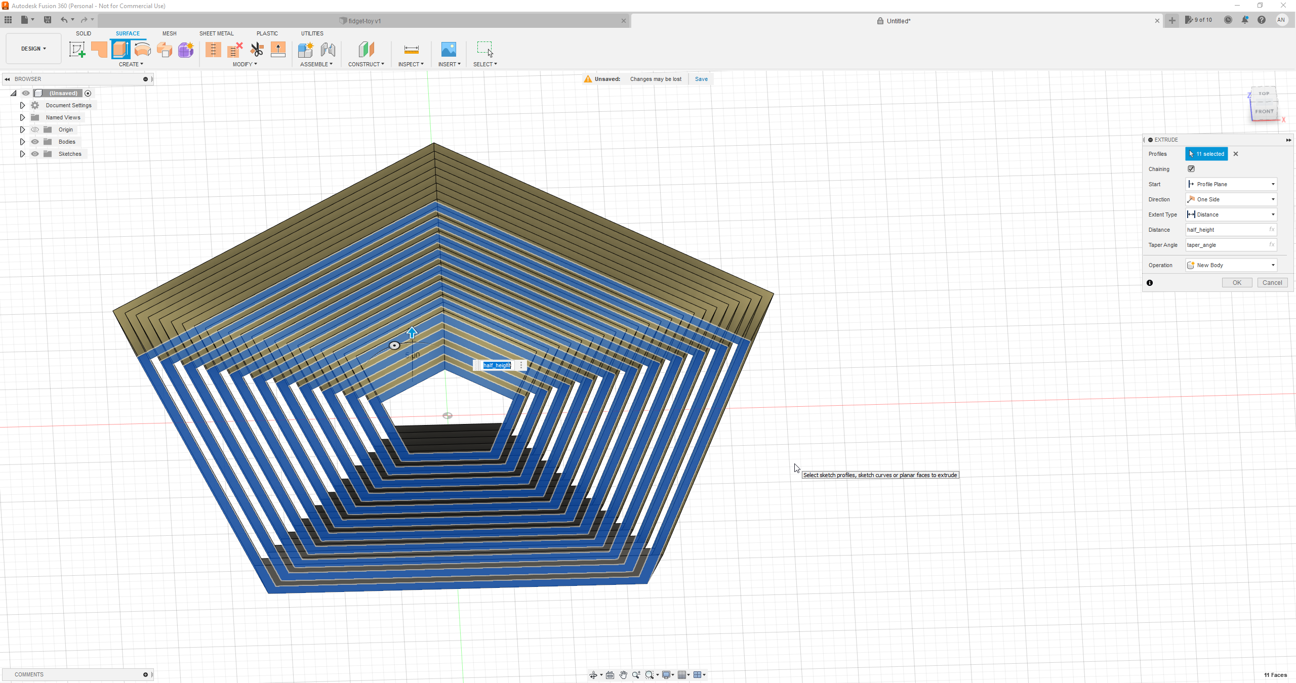
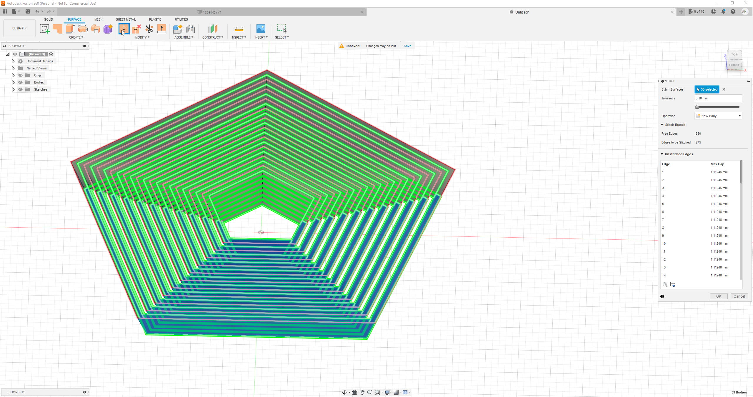
With all planar rings in place, go to Surface > Create > Extrude. Select everything and edit the following inputs:
- Distance: type half_height or -half_height (depending on the ring construction method, surface normals might cause the surface to extrude downwards; we want it to extrude upwards)
- Taper angle: type taper_angle
Next, select all newly created bodies, then go to Modify > Stitch, and finally click OK to join them all into a single one.
Mirroring
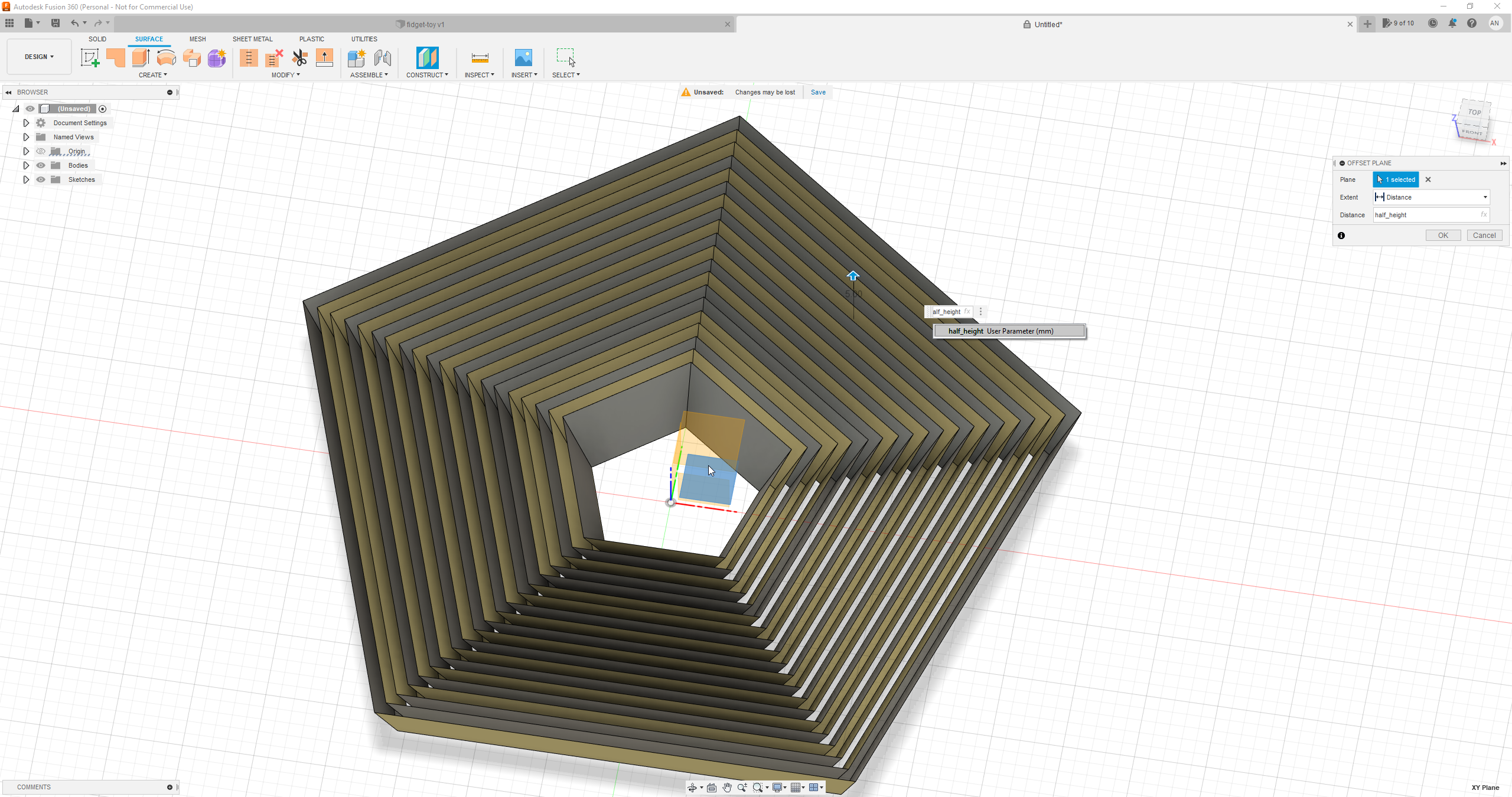
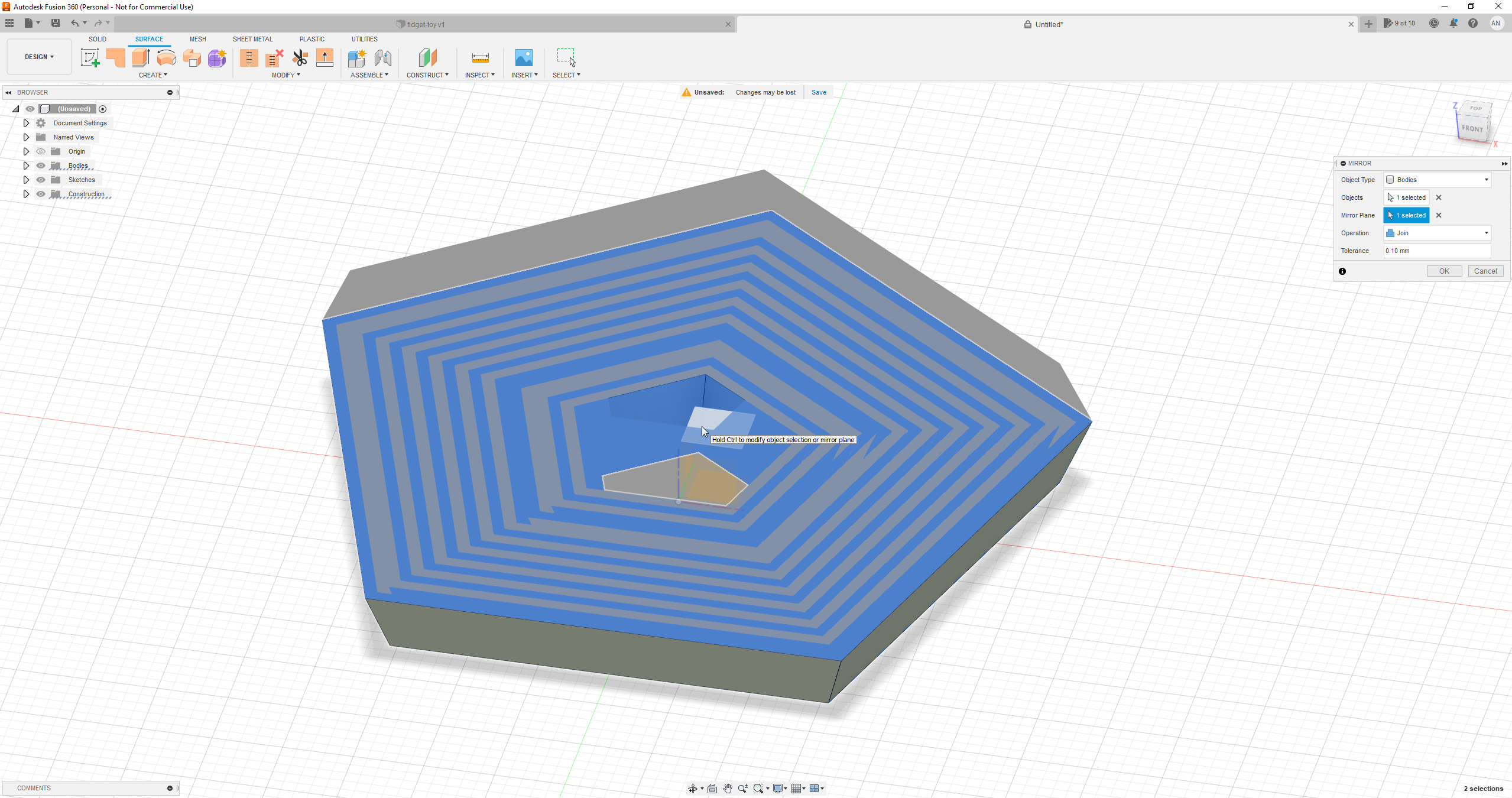
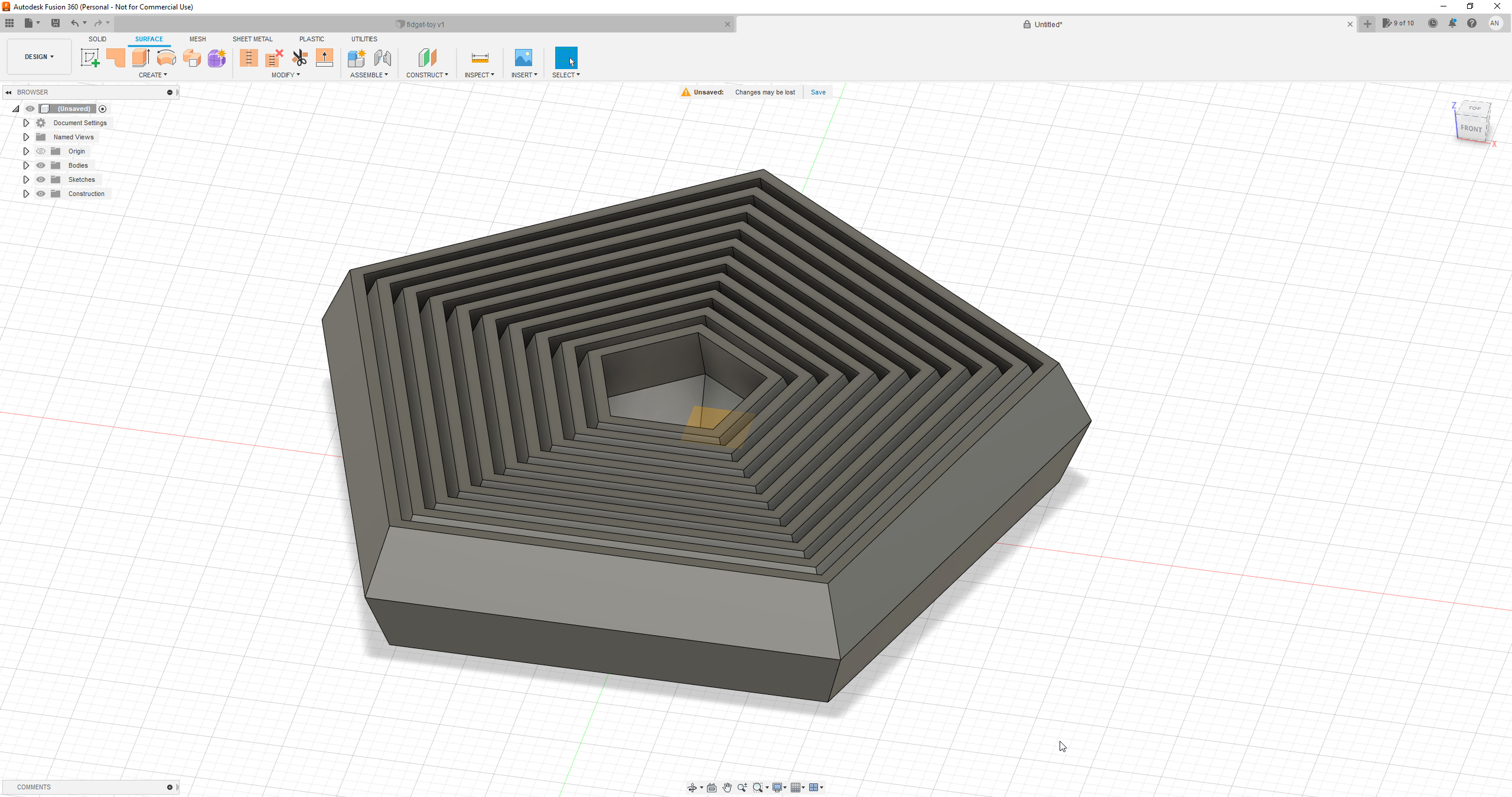
Go to Construct > Offset Plane, select the xy plane and set the Distance to half_height. Finally, go to Surface > Mirror and edit the following inputs:
- Objects: select the surface object we just created
- Mirror Plane: select the offset plane
Make sure the Operation is set to Join. That's it! Our object is now a solid, ready to be exported and printed. Select it, right-click, and choose Save As Mesh from the menu.
Printing
Bed adhesion, first layer calibration, and extrusion calibration are really important for a successful print. It is best to print the first layer slowly. Extrusion and retraction settings are important to ensure the rings do not fuse together at the seam. If you encounter issues, try placing seams away from corners. You might benefit from a brim, especially when printing the square version.
Conclusion
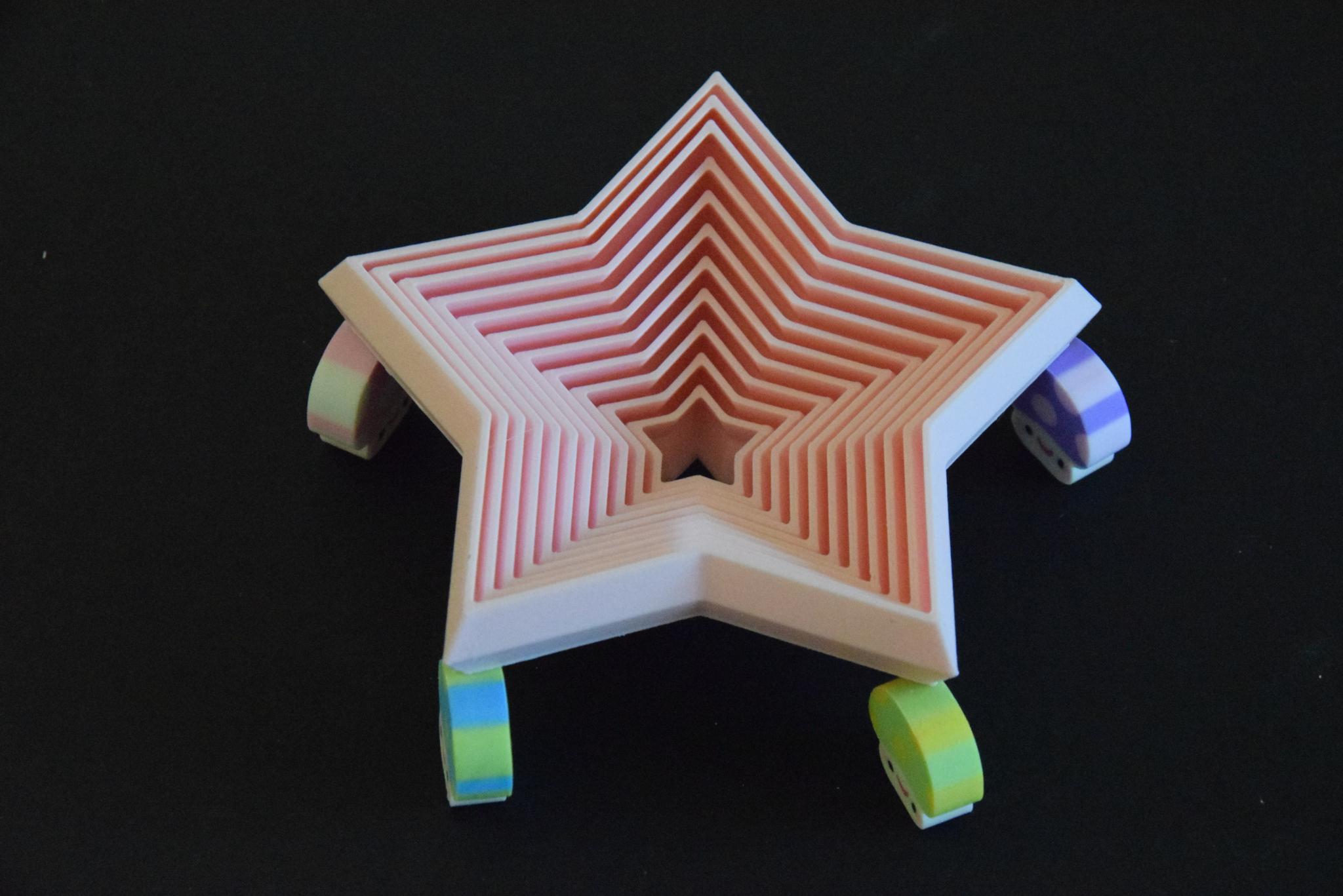
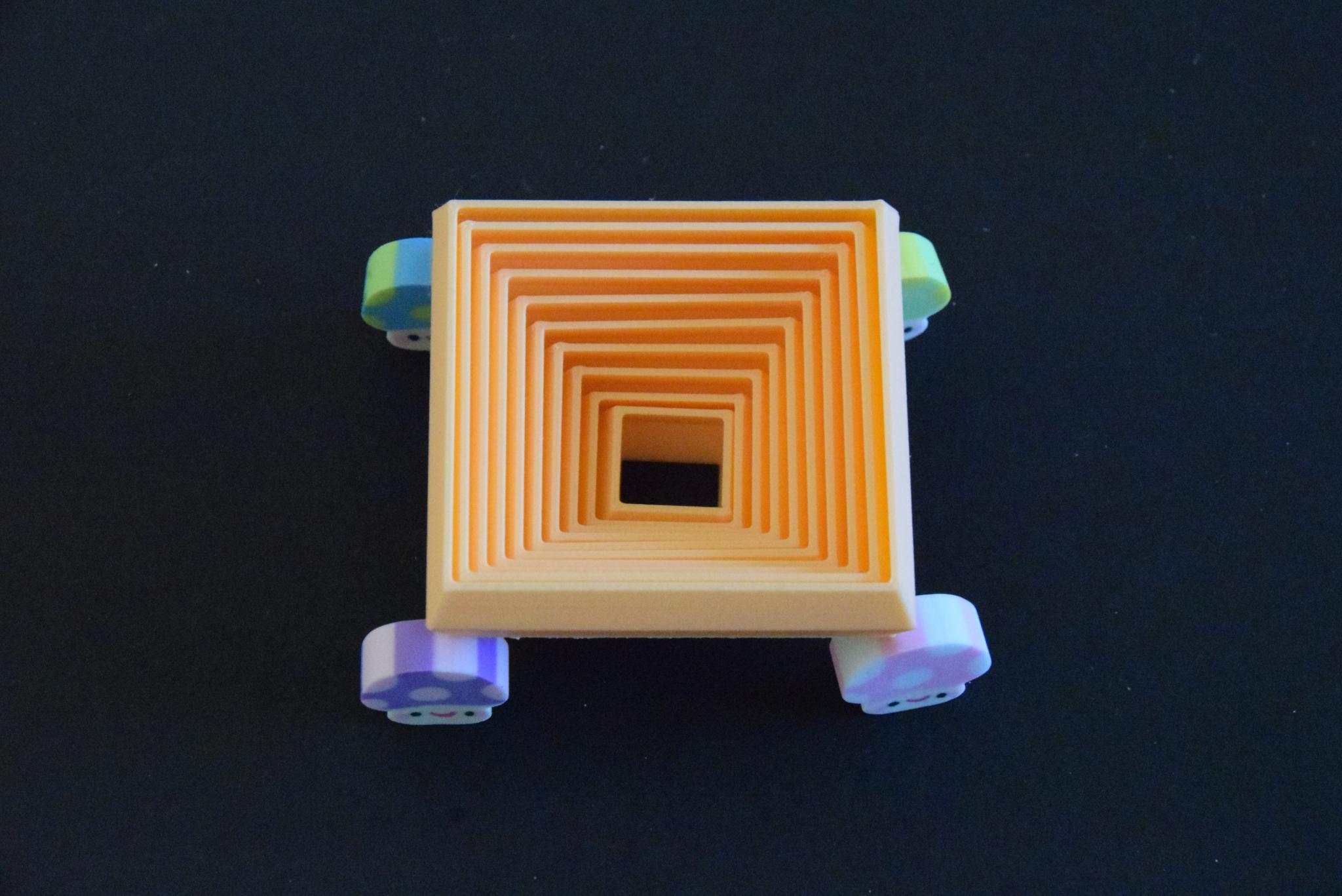
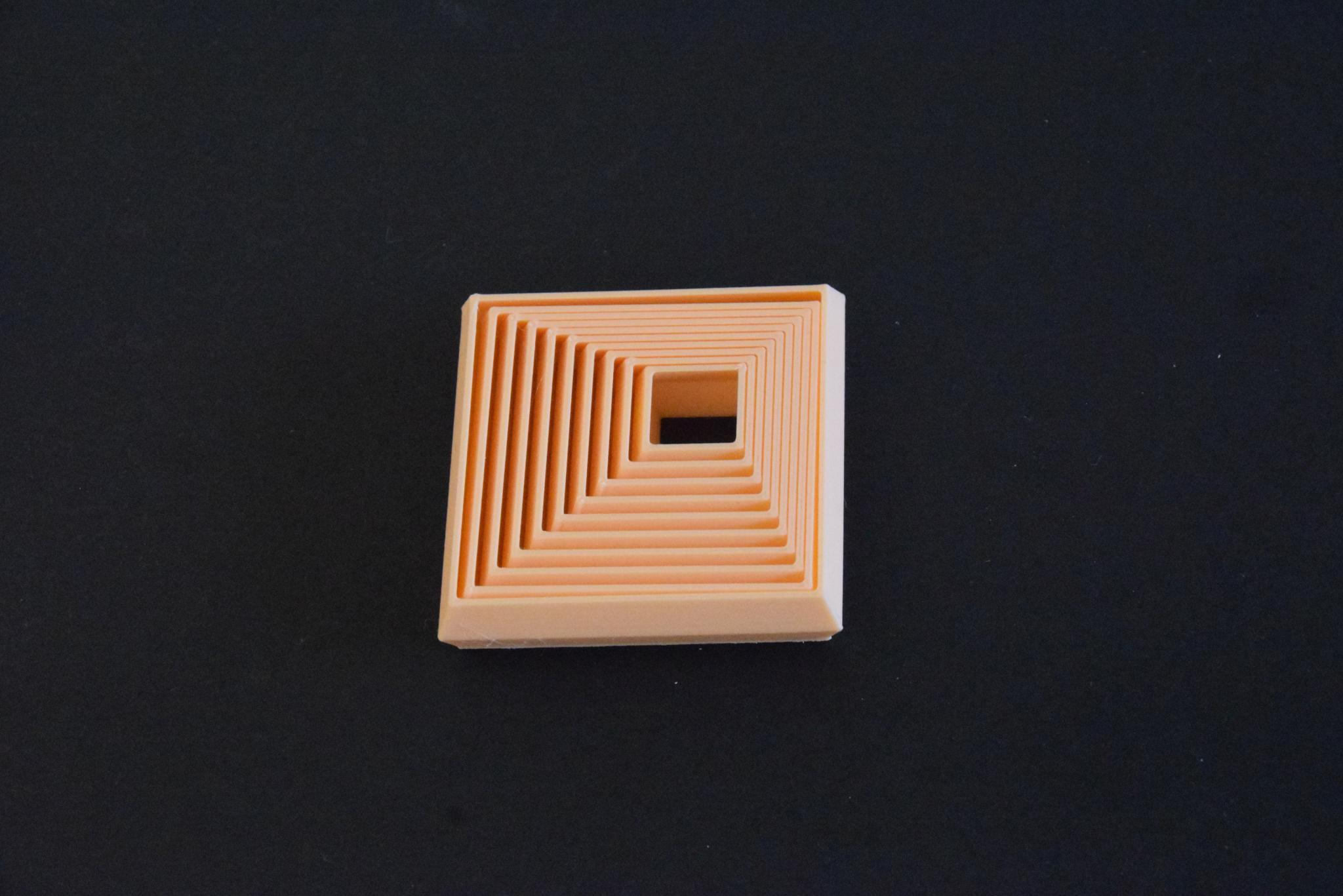
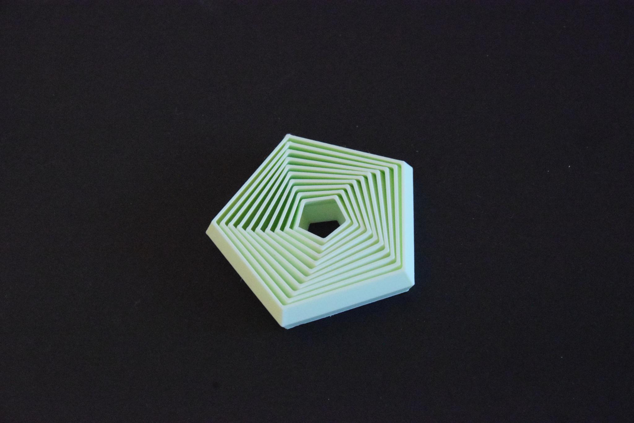
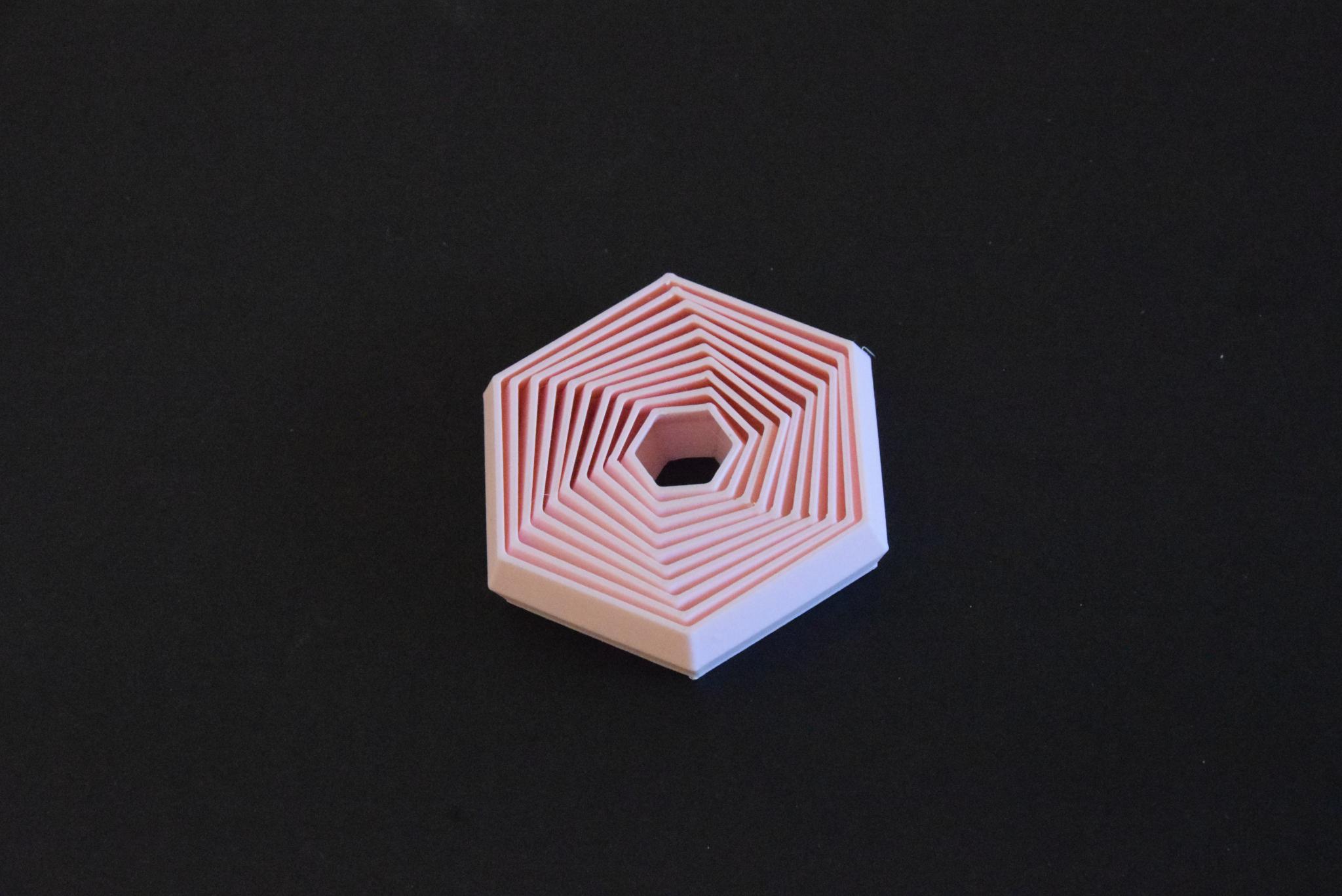
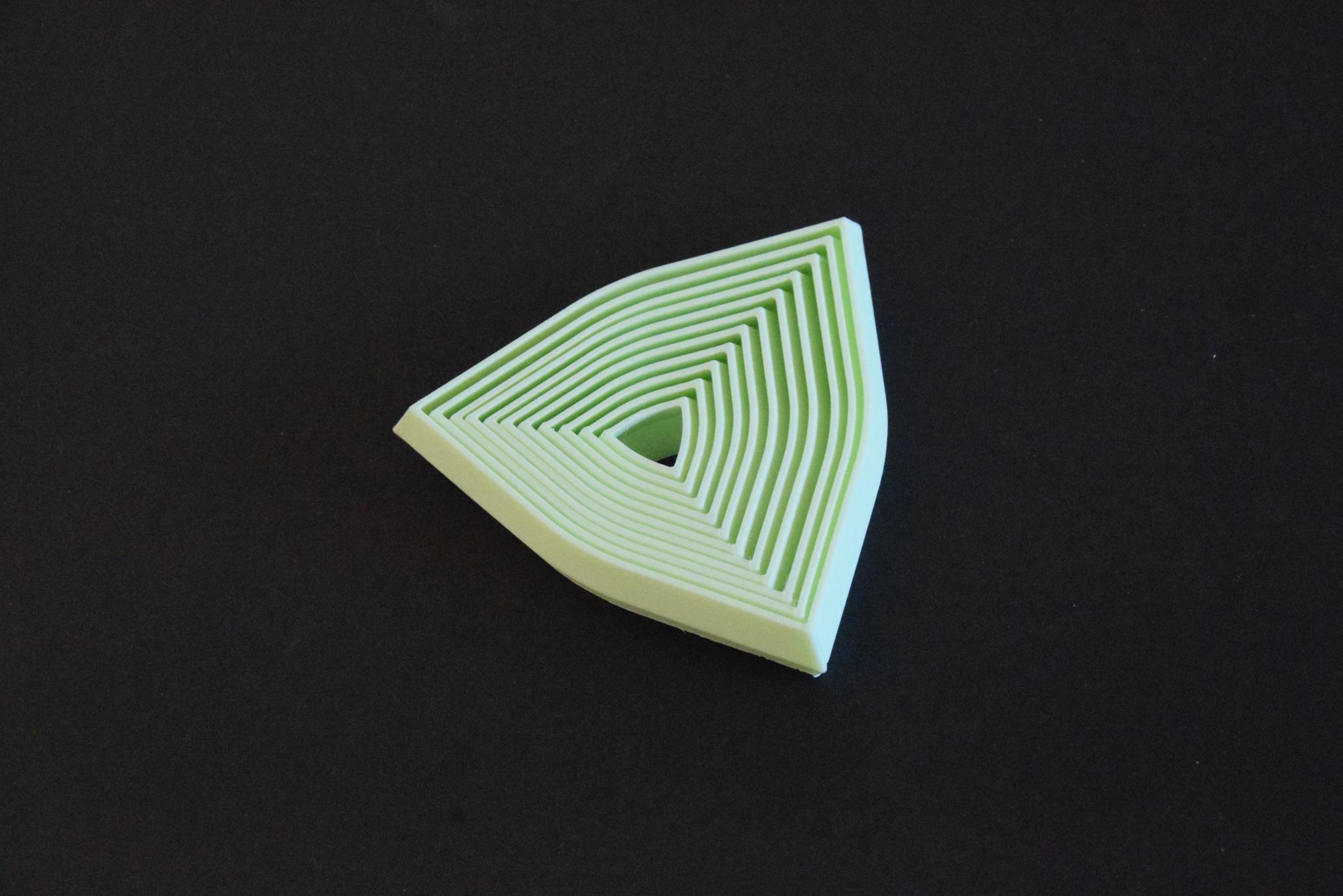
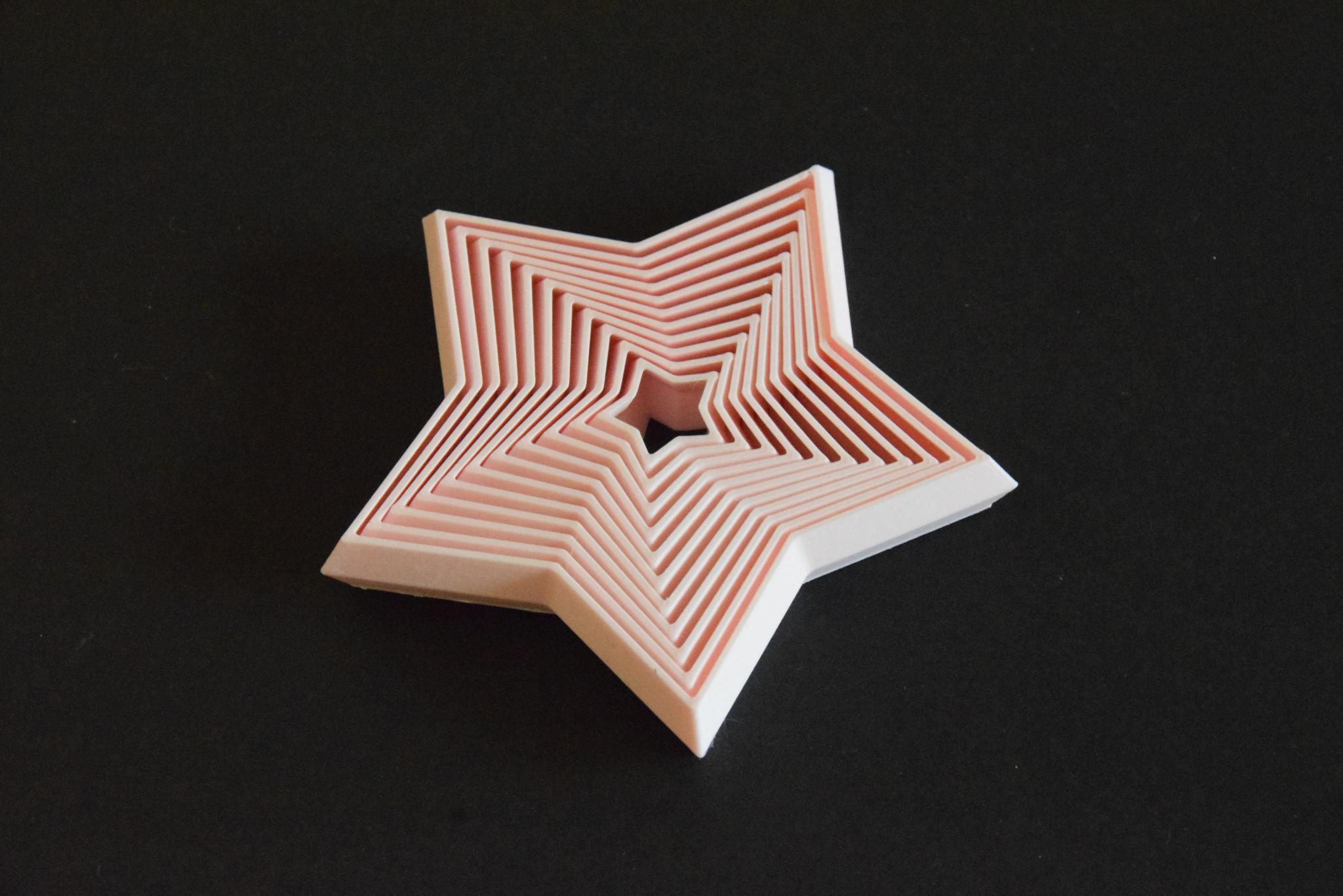
You now have an amazing toy which will make you super-focused and stress-free! You will probably also achieve a reputation as the best gift-giver amongst your friends, or perhaps even launch a successful ASMR career!