Command Stepper Motor With Arduino Assembler Avr Code
by BoboacaC in Circuits > Arduino
225 Views, 0 Favorites, 0 Comments
Command Stepper Motor With Arduino Assembler Avr Code
In this tutorial will show you how turn a stepper motor with only 30 bytes assembler code 28,98,56,9A,5B,98,4E,9A,08,EC,01,D0,FC,CF,0A,95,F1,F7,08,95,E1,F7,08,95,08,95,E1,F7,08,95
Supplies
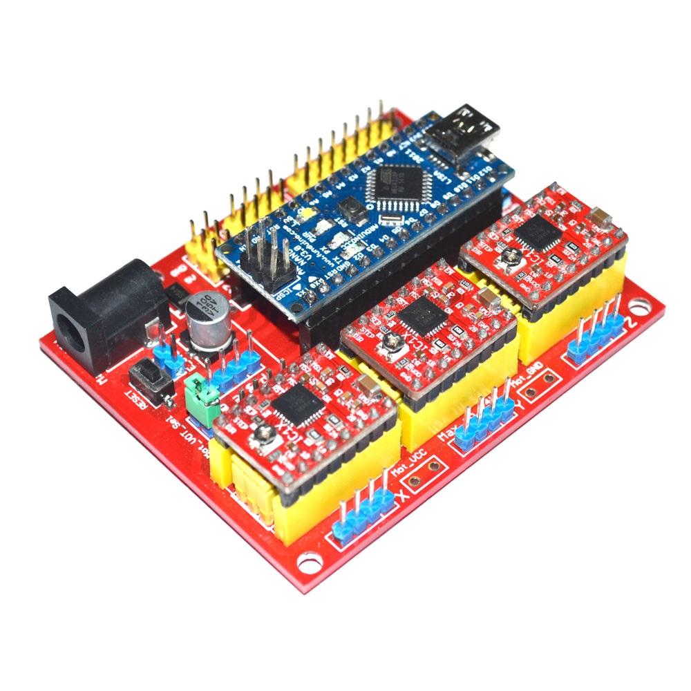
For this you need to have this cnc shield v4.0 with arduino nano where will write this assembler code with https://www.costycnc.it/avr-hex-uploader
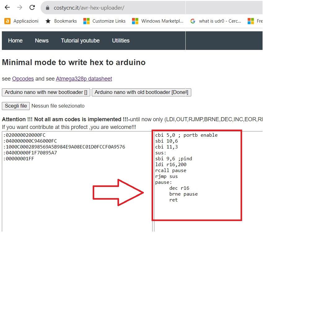
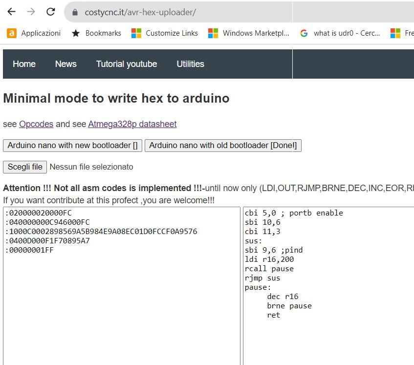
Go to https://www.costycnc.it/avr-hex-uploader and insert this asm code :
cbi 5,0 ; portb enable
sbi 10,6
cbi 11,3
sus:
sbi 9,6 ;pind
ldi r16,200
rcall pause
rjmp sus
pause:
dec r16
brne pause
ret
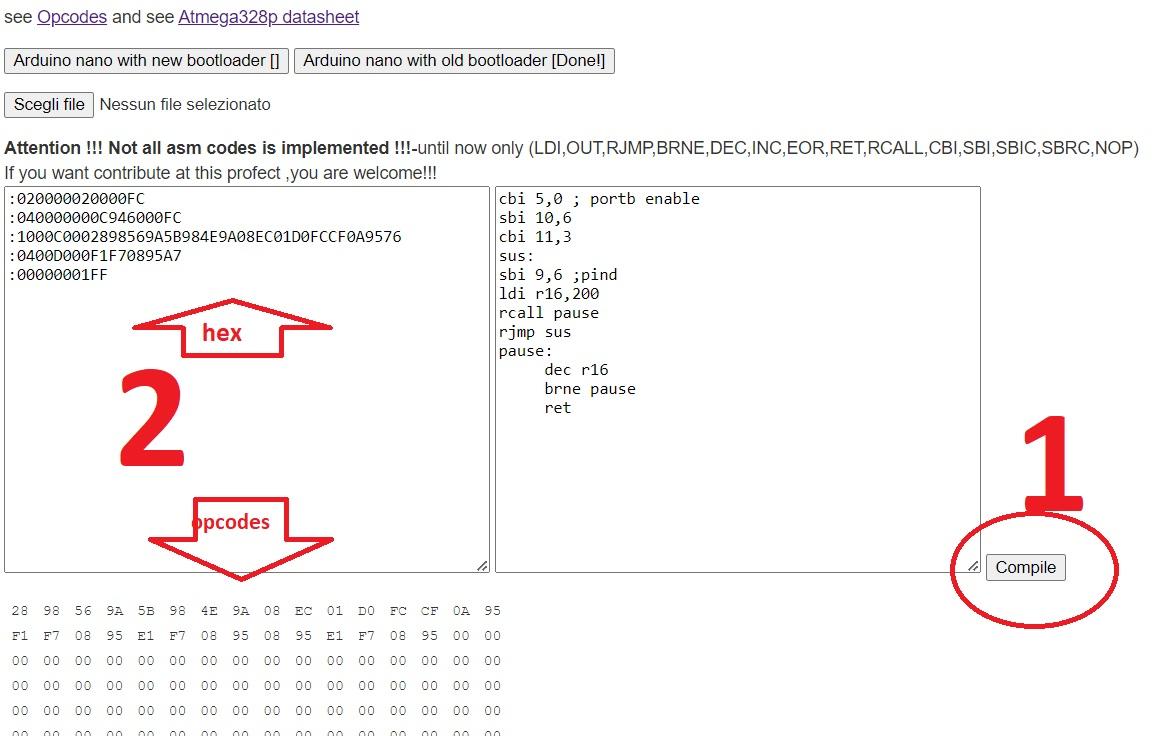
- After insert asm code if click button "compile"
- If code not have problems, will see the opcodes and hex create without problems
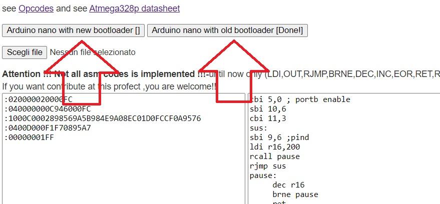
Now click one of this button to upload code to arduino.
The arduino is sell in two variants : velocity for upload code 57600 (old) and 115200 new.
If you dont know what arduino have ,with old or new bootloader , only try to upload with first button , if give error, try second button!
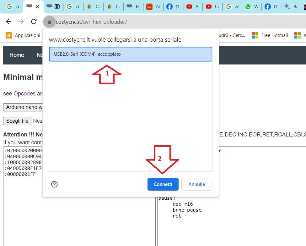
If you haved connected with arduino over usb cable will see in this box the com port .
If have many ports and dont know what port is for arduino ... disconnect usb cable and port of arduino dissapear from this box ... when insert again usb cable the port where is conected arduino will appear again.
1 Clik this port
2 Click "connect" button
If have inserted 12 volt and the stepper motor is connected ... the stepper motor will turn!
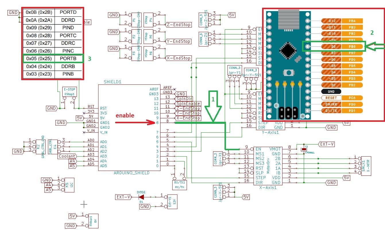
First need to understand what signals need to cnc shield v4.0 to working.
For turn a "X" motor need to have "0" on pin enable and "0" AND "1" alternate to make stepping.
If see the schematics of cnc shield v4.0 ,the "Enable" com to 8 (D8) pin of arduino.(1 with green)
If look the arduino board , the D8 is PORTB - PIN0 ... so PORTB0 (2 with green)
So need to make this pin 0 over code.
Portb is port 5 (3 with green)
My compiler from https://costycnc.it/avr-hex-uploader not support yet PORTB instruction... so need to put 5
CBI mean clear pin on the port, so:
cbi 5,0 mean clear pin 0 on port B ... that mean if put PORTB0 on 0 the module a4988 is not blocking
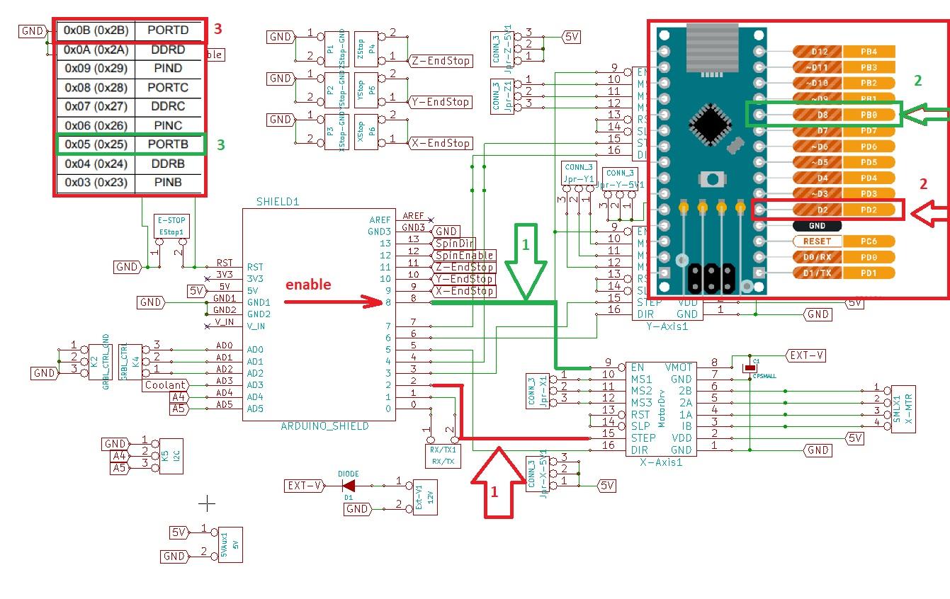
Now need to put pulse ON and OFF on pin 2 (PD2) that is PORTD .
But if DDRD is not set the PORTD will go in "1" but not have enough power to command shield , so need to put also DDRD in 1 .
So put DDRD pin 2 high --> sbi 10,2
OPTIONAL: PORTB pin 2 is direction and can be ommited if want turn motor only a direction --> cbi 11,2