AVR Assembler Tutorial 4
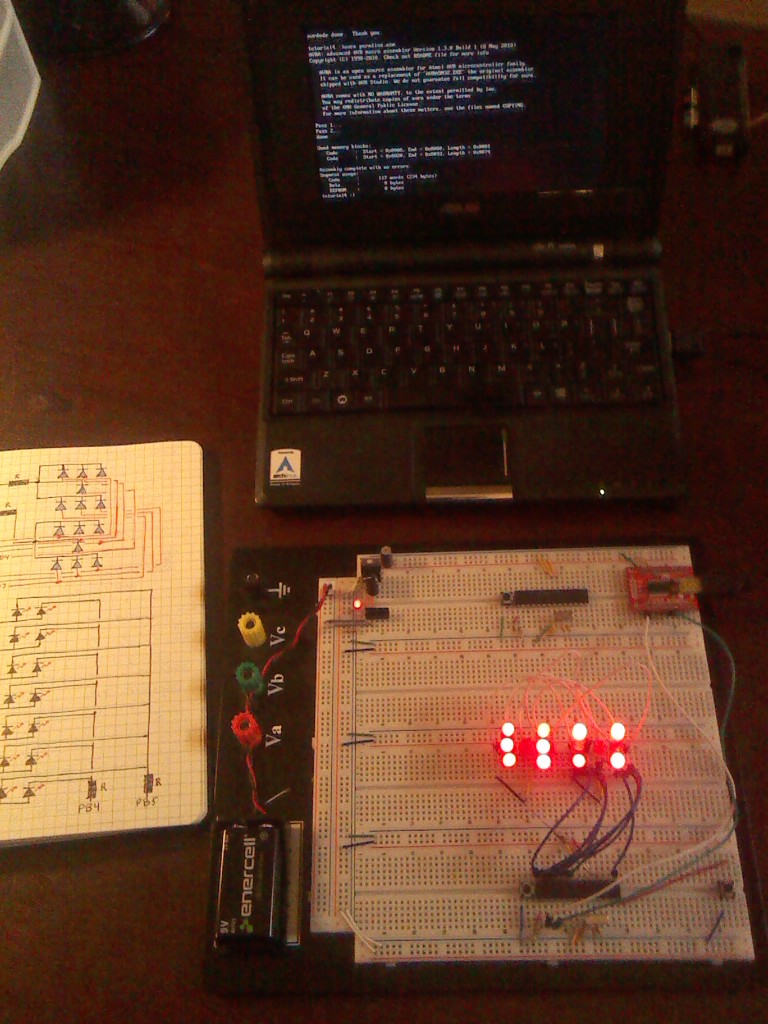
Welcome to tutorial number 4!
In this tutorial we will be building a circuit which will simulate the rolling of two dice. Then we will first write a brute-force program that does the job. Then we will simplify that program in various ways by introducing some new concepts such as "macros" and "lookup tables" so that the final result is more compact and elegant.
Okay then, let's get at it!
Here is what you will need:
- your prototyping board
- 14 LEDs
- a bunch of wires
- 2 resistor, the size depends on your leds. I use a 100 ohm and a 220 ohm
- a push button
- a copy of the Datasheet: www.atmel.com/images/Atmel-8271-8-bit-AVR-Microcon...
- a copy of the AVR instruction set manual: http://www.atmel.com/images/Atmel-0856-AVR-Instruction-Set-Manual.pdf
- coffee, stamina, and several hours of free time
Here is a link to the complete collection of these tutorials: https://www.instructables.com/id/Command-Line-AVR-T...
Build the Circuit
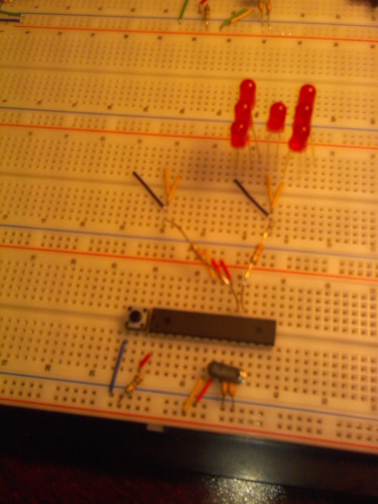
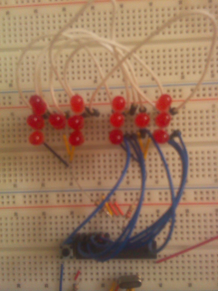
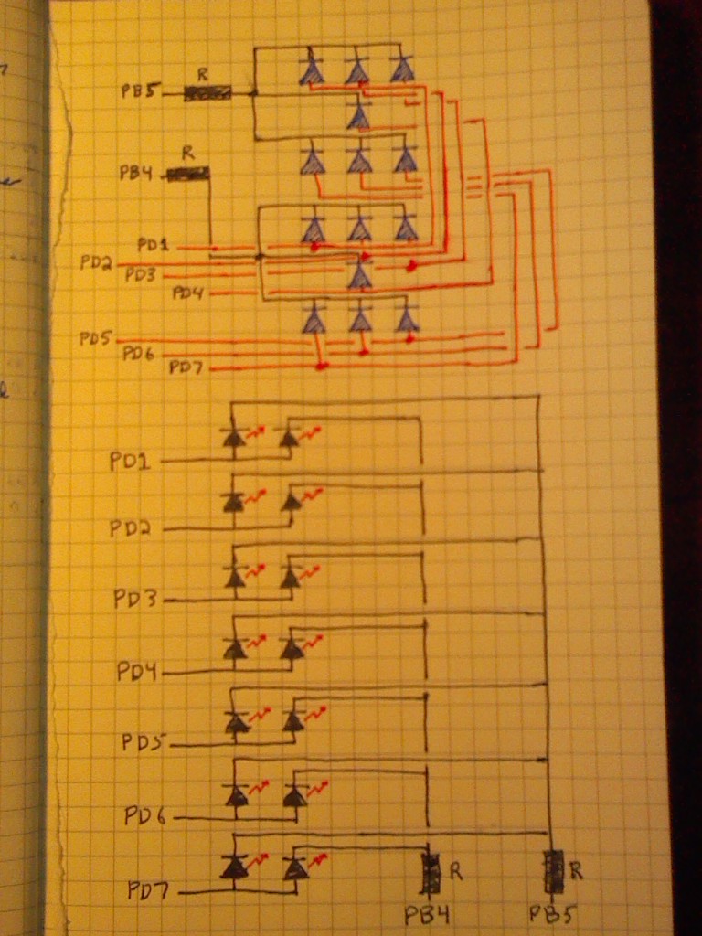
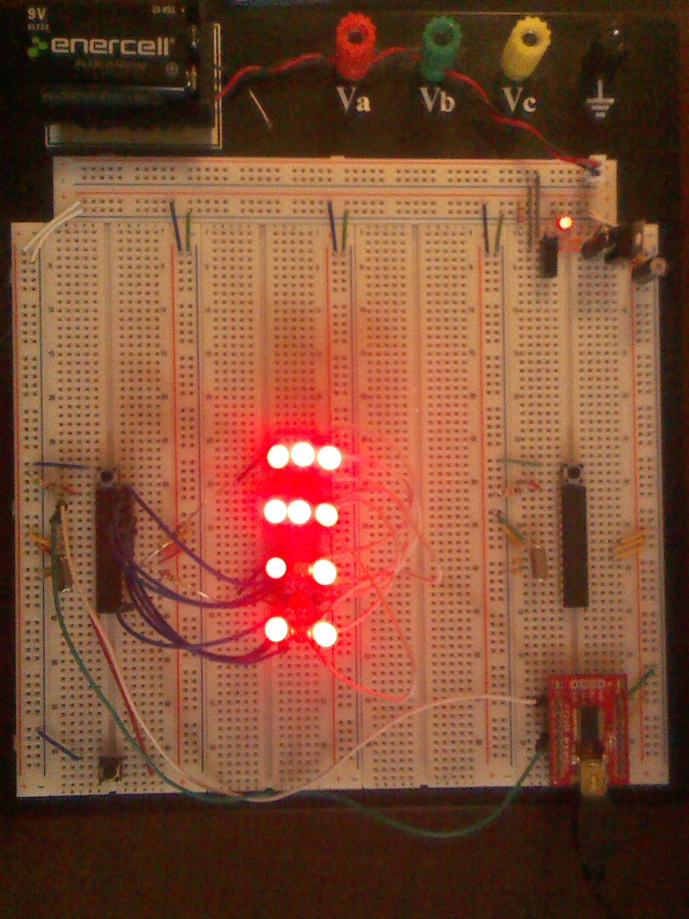
The last picture shows the wiring diagram. However, I changed it slightly since I made the diagram in that I reversed each LED from what is shown in the diagram so that the current flows to the port from the resistor side, and I also decided to use PortC to wire the LEDs rather than PortD as shown in the picture. The reason is that PortD contains the TX and TX pins for the programmer and that left not enough pins to do what I want. Also PortB contains the crystal oscillator so again there are not enough pins for me. Hence I am using PortC. That gives me 6 pins for the outer LEDs on a die and the center LED I will control with pin PB1.
As you can see by the other two pictures, the way I have wired the LEDs is so that all of the anodes (the long wire which is connected to POSITIVE) for each LED are connected together for each die whereas the cathodes (the shorter wire) for each die are connected to the different pins. The anodes from die1 are connected to PB4 through a 220 ohm resistor, and the anodes from die2 are connected to PB5 through a 220 ohm resistor. The cathodes are connected to ports PC0 through PC5 and the center LED on PB1.
Notice that I have connected the two dice together so that each LED on one die is connected to the corresponding LED in the second die which is at the same spot on the die.
I have a pushbutton connected to PB0 and from there to GND so that when the button is pressed, it brings PB0 to GND.
Now let me briefly explain the operation. All of the pins on PortC and also PB1 which are connected to the cathodes of the LEDs will be normally set at 5V. Also, the pins connected to the anodes, PB4 and PB5 will normally be at 5V. So no current will flow and the LEDs will remain off. Then, when I put a pin to 0V current will flow and one or more LED's will light up.
For example, say I want to light up die number 2 (on the left) so that it shows a 3. I would put PB1 to 0V, PC0 to 0V, and PC5 to 0V. I will also put PB4 to 0V so that die1 does not light up.
So that is the setup on your prototyping board. If I continue to make these tutorials I think we will eventually solder these dice onto a perfboard with a header on it so that we can use it without filling up our prototyping board. Then we can use that space for the other things that I have planned.
First Draft of the Code
The first version of the code we are going to write to drive this circuit is called the "brute force" method. We will just write a program that works and not worry just yet about making it compact and "beautiful". We will make it more elegant later. The way I am doing things is to make sure you can get your program working and doing what it does without introducing too many new concepts. Once you have it working, then we will adjust things with new concepts a piece at a time so that the program will still work correctly at every iteration. That way if something goes wrong, you will know exactly where the problem is coming from.
So let's start with the following program to roll the dice. You should assemble it, upload it, and make sure it works on your microprocessor.
;********************************
; written by: 1o_o7
; date: <2014|11|01>
;********************************

; Program funcion:---------------
;
; A dice roller
;
; LEDs on PC0 through 5
; and the center one on PB1
; Button on PB0
; anodes on PB4 and PB5
;
;--------------------------------

.nolist
.include "m328Pdef.inc"
.list

;=================
; Declarations:

.def temp         = r16
.def overflows    = r17
.def die1         = r18
.def die2         = r19
.def milliseconds = r20
.def seed         = r21

;=================
; Start of Program

.org 0x0000
rjmp Reset
.org 0x0020             ; Timer0 overflow handler
rjmp overflow_handler

;=================

Reset:
   ldi temp,0b00000011
   out TCCR0B,temp     ; TCNT0 in FCPU/64 mode, so 250000 cnts/sec
   ldi temp,249
   out OCR0A, temp     ; top of counter at 250 counts/overflow
                       ;   so overflow occurs every 1/1000 sec
                       ;   this means an overflow every 1ms
   ldi temp,0b00000010
   out TCCR0A, temp    ; reset TCNT0 at value in OCR0A
   sts TIMSK0, temp    ; Enable Timer Overflow Interrupts
   sei                 ; enable global interrupts

   ldi temp,0b11111110
   out DDRB,temp       ; PB0 input the rest output
   ldi temp,0b11111111
   out DDRC,temp       ; PortC all output

main:
  ser temp
  out PORTB,temp      ; all PortB at 5V
  out PORTC,temp      ; all PortC at 5V
  rcall button_push   ; wait for button
  rcall random        ; get rand nums die1, die2
  rcall dice          ; set up dice leds
  ser temp            ; set temp for cycle
  rcall cycle         ; animate dice throw
  rcall display       ; display the result
rjmp main

button_push:
   sbic PINB,0        ; skip if PB0 is GND
   rjmp button_push
ret

random:
         ; attempt to generate random numbers
   add die1,seed
   swap seed
   rcall delay
   add die2,seed
   clc
  d1:
   cpi die1,6   ; compare die1 with 6
   brlo d2      ; if die1 < 6 then go to d2
   subi die1,6  ; else subtract 6
   rjmp d1      ; go back and compare again
  d2:
   cpi die2,6   ; compare die2 with 6
   brlo roll    ; if die < 6 then roll
   subi die2,6  ; else subtract 6
   rjmp d2      ; go back and compare again
  roll:
   inc die1     ; add 1 so between 1 and 6
   inc die2
ret

dice:
   cpi die1, 1         ; compare die1 with 1
   brne PC+2           ; if not equal don't set die1
   ldi die1,0b01111111 ; 7th bit set off denotes a 1
   cpi die2, 1         ; compare die2 with 1
   brne PC+2           ; if not equal don't set die2
   ldi die2,0b01111111

   cpi die1, 2
   brne PC+2
   ldi die1,0b11011110
   cpi die2, 2
   brne PC+2
   ldi die2,0b11011110

   cpi die1, 3
   brne PC+2
   ldi die1,0b01011110
   cpi die2, 3
   brne PC+2
   ldi die2,0b01011110

   cpi die1, 4
   brne PC+2
   ldi die1,0b11010010
   cpi die2, 4
   brne PC+2
   ldi die2,0b11010010

   cpi die1, 5
   brne PC+2
   ldi die1,0b01010010 ; a 4 bit with 7th bit off so 5
   cpi die2, 5
   brne PC+2
   ldi die2,0b01010010

   cpi die1, 6
   brne PC+2
   ldi die1,0b11000000
   cpi die2, 6
   brne PC+2
   ldi die2,0b11000000
ret

cycle:
   rol temp            ; shift bits left with wrap around
   ldi milliseconds,100; delay (up to 250 ms)
   rcall delay
   sec                 ; set the SREG carry flag
   out PORTC,temp      ; PortC starts as 0b11111110
   sbrc temp,6         ; skip if bit 6 is cleared
   rjmp cycle          ; otherwise loop back up
ret


display:
   sbi PORTB,0         ; set button to off
   sbi PORTB,1         ; turn off center led
   ldi milliseconds,2  ; set a short delay
   sbi PORTB,4         ; turn on die1
   cbi PORTB,5         ; turn off die2
   sbrs die1,7         ; skip if center led off
   cbi PORTB,1         ; turn on center led if needed
   out PORTC,die1      ; turn on the others
  rcall delay          ; short delay
   sbi PORTB,1         ; turn off center led
   cbi PORTB,4         ; turn off die1
   sbi PORTB,5         ; turn on die2
   sbrs die2,7         ; skip if center led off
   cbi PORTB,1         ; turn on center led if needed
   out PORTC,die2      ; turn on the others
  rcall delay          ; short delay
   sbic PINB,0         ; exit to main if button press
   rjmp display        ; loop to the top
ret

delay:
   clr overflows
  sec_count:
   cpse overflows, milliseconds
  rjmp sec_count
ret

overflow_handler:
   inc overflows       ; increment 1000 times/sec
   add seed,overflows
reti
Timer/Counter 0

From now on I am not going to go into detail about the parts of the code that you already understand from previous parts of these tutorials. Also, if you see any instructions that look new or you don't remember what they do, you already know what to do. You can turn to the instruction set summary in the datasheet and remind yourself that way, or you can go to the full Instruction Set Manual which has a more detailed explanation of each instruction and even sample code of how it is used. I think you will find it a useful manual if you plan to continue coding in assembly language. What we will do henceforth, instead of line-by-line analysis, is discuss the new concepts that we are introducing that you haven't seen before in these tutorials.
So, before we get to subroutines, lets begin by taking a look at our clock timer. You recall that last tutorial we showed how to use interrupts and the timer/counter TCNT0 to create a method to have delays in our program where we need them. You will notice that, this time, we have changed it slightly. Here is the code I am talking about:
Reset:
   ldi temp,0b00000011
   out TCCR0B,temp     ; TCNT0 in FCPU/64 mode, 250000 cnts/sec
   ldi temp,249
   out OCR0A, temp     ; top of counter at 250 counts/overflow
                       ;   so overflow occurs every 1/1000 sec
                       ;   this means an overflow every 1ms
   ldi temp,0b00000010
   out TCCR0A,temp     ; reset TCNT0 at top of OCR0A
   sts TIMSK0, temp    ; Enable Timer Overflow Interrupts
   sei                 ; enable global interrupts
As you can see, instead of FCPU/1024 like we used last time, this time we are using FCPU/64. This means that our timer will tick at a rate of
TCNT0 rate = 16000000/64 = 250000 ticks per second.
Now we introduce something new. the OCR0A Output Compare Register A (see page 108 of the datasheet). We set a value of 249 in this register (see table 15-1 page 94). Then we set the Wave Generation Mode pin WGM01 in TCCR0A and we see by table 15-8 on page 106 that this means the timer will clear and reset whenever it reaches the value we have placed in OCR0A. In other words it will reset back to 0 when the timer reaches 249. This means that it will overflow once every 250 counts. Since it counts at a rate of 250000 ticks per second, it takes 1/1000 of a second to overflow. Hence TCNT0 now overflows every millisecond.
Then we enable timer overflow interrupts and also global interrupts as we explained in tutorial 3.
I think you will agree that timer/counters are complicated things. There are three different counters in the microcontroller and you can use them to time and interrupt in different combinations if you want to time different things or you want to compare the time it takes to do one thing as opposed to another. The uses are endless and important. For now we will only be using TCNT0 since I think getting used to it is complicated enough.
A good way to view all of these special registers like TCCR0A, TCCR0A, TIMSK0, and the like is as a panel with toggle switches on it. Like in a NASA control room or a Ham radio operators set up. You can toggle on and off various switches and this will control how the device works. In this case the timer TCNT0. I have included a picture from my graduate student days in particle physics standing in the control room of an accelerator laboratory. Sometimes coding these chips can feel like that.
The reason that we have set it up to overflow every ms is so that we can create a "delay" subroutine which will delay in milliseconds (just like the Arduino "delay()" function).
In our code you can see that we have implemented this with a subroutine which counts the number of overflows and compares that value with the number of milliseconds we want to delay.
Subroutines
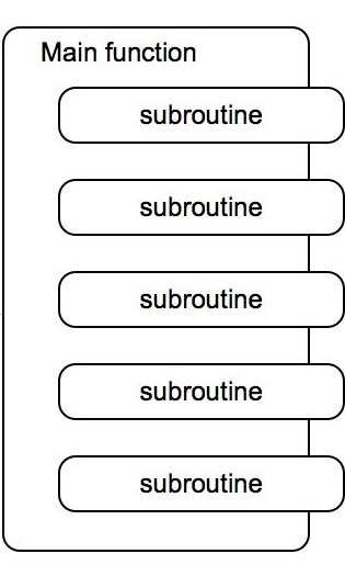
Something that you will immediately notice about the way I write code can be seen by looking at the section after the label "main:"
main:
  ser temp
  out PORTB,temp      ; all PortB at 5V
  out PORTC,temp      ; all PortC at 5V
  rcall button_push   ; wait for button
  rcall random        ; get rand nums die1, die2
  rcall dice          ; set up dice LEDs
  ser temp            ; set temp for cycle
  rcall cycle         ; animate dice throw
  rcall display       ; display the result
rjmp main
Notice that everything is contained between the label "main:" at the top and the "rjmp main" at the bottom. This means that there is no escape from this section other than via the "rcall" statements inside. Now take a look at one of the rcall statements, "rcall button_push" this jumps us to the section under the label "button_push"
button_push:
   sbic PINB,0        ; skip if PB0 is GND
   rjmp button_push
ret
You see that this section is also contained between a label and a "ret" so that the PC is also trapped inside here as well. This section of code is called a "subroutine" since I call it from the main block, it executes some task, and then it "returns" to main at the place where it was called. Thus using subroutines like this allows you to block out the code into chunks that perform certain tasks and then return to where they were called. The advantages of coding this way are as follows:
- if you find yourself performing the same task several times you can just call the subroutine rather than have the same set of commands repeated over and over. The result is a shorter program that does the same thing.
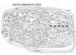
- it is much easier to read the program and figure out what it does unlike the "spaghetti code" that some people write where everything is one long section that jumps around back and forth, to and fro, all over the place until a person needs a jug of whiskey sitting beside him when reading it to stave off insanity.
- it is way easier to debug! If your program doesn't work and you have no idea why (which is usually the case when writing in assembly language) you can easily do some detective work and isolate the error to one of the subroutines and then figure it out from there. The result is hours of time saved.
So you will see that I use subroutines "routinely" in my programs ;)
Exercise 1: Examine the subroutine that I use to display the values on the dice by lighting up various LEDs. You will see that I am actually flipping back and forth from one die to the other. If you change the delays in the "display" subroutine you will see this flicker. The fact that the eye can't see flickers that are too fast allows me to power two LED's from the same wire and just flip back and forth really fast so that the eye sees them both as being on all the time. That way instead of needing an output port for each LED (so a total of 16 including the 0V and the 5V ports) we only need 9. Can you think of a better way to do this so that we don't have to use 7 of our ports to power these dice? What about "Charlieplexing the LEDs" like I did in my "instructable" about Charlieplexing? ( https://www.instructables.com/id/Spectrometer-using-Charleplexed-LEDs/ ) Would that be worth it in the long run with only 14 LEDs?
The next thing we will start using is "Macros".
Macros

Macros are very similar to the subroutines that we discussed in the last step except that they take "arguments". In other words, macros are essentially "functions." In fact, the main difference between assembly language and all of the "higher level" languages that people use is that somebody has compiled a bunch of frequently used functions into macros. Here we will use macros to achieve the same ends, with one important difference, our macros will be right there in the code for us to see and modify as we like.
Our philosophy in these tutorials is to get rid of all of the "black boxes" and find out what is going on behind the scenes. We don't want anything happening unless we know about it and told it to do that. That is why this is called "Command Line Assembly Language Programming". We are using the command line instead of some Java based IDE like the arduino one (in fact, I use the command line even with arduino programming). A java ide window is like a black box to me. I can never be absolutely certain that there aren't assumptions being made behind the scenes when communicating my instructions to the microcontroller and I don't like that. I also don't like how bloated and cpu consuming java is. In fact, that is also why we are using "avra" rather than the ATmel assembler IDE. I realize that when you are an expert coder, or a complete novice, you already know, or you don't care, what is happening behind the scenes, but here we will sacrifice the convenience to avoid black-boxness and fatness.
Now what are macros anyway? Well you may have noticed when reading through the program that we use the "delay" subroutine all over the place. Not just from inside main, but from inside other subroutines as well. This leads to spaghetti and we don't like spaghetti. (draw lines between each subroutine block of code in your diagram when one block calls another and you will quickly see that the "delay" subroutine causes the diagram to look like a bowl of spaghetti)
Here is how "delay" is usually called:
ldi milliseconds,50 ; delay (up to 250 ms)
rcall delay
You see that we first set the variable (i.e. working register) "milliseconds" to the value 25 and then we call the subroutine "delay". The subroutine will delay 25 ms and then return. Aside from spaghetti, another problem with this way of doing things is that if we forget to set the value of milliseconds immediately before we call the subroutine we will have no idea what the delay will be. It will be whatever value we put into milliseconds somewhere else. This is a risky way to write code. So to solve all this we simply write a "macro". Here 'tis:
.macro delay
   clr overflows
   ldi milliseconds,@0
  sec_count:
   cpse overflows, milliseconds
  rjmp sec_count
.endmacro
It is an assembler directive that we put at the top of our program that does the same delay stuff we had in our delay subroutine, it is called delay, but it has the important difference that we set the variable "milliseconds" inside it! The symbol @0 (ampersand zero) stands for whatever we place next to delay when we call it. Here is how we call it then. If we wanted a delay of 25ms somewhere in our program we simply write
delay 25
and the assembler will replace the @0 in the macro with 25 and we get our delay of 25 ms.
Why @0? well you can write macros that have many more arguments if you like. In that case you would use @1 and @2, @3, and so on. Then when you call the function you would need to supply all the arguments corresponding to these @ things in the macro.
I think now you can see how they made the Arduino language "delay(20)" command right?
Exercise 2: Add a macro into the program and change all of the subroutines so that they call the macro instead of a delay subroutine. (note! In one of the incidents you will have to search around to figure out what the delay is supposed to be! I deliberately left out the ldi milliseconds in that case)
Pointers and Lookup Tables
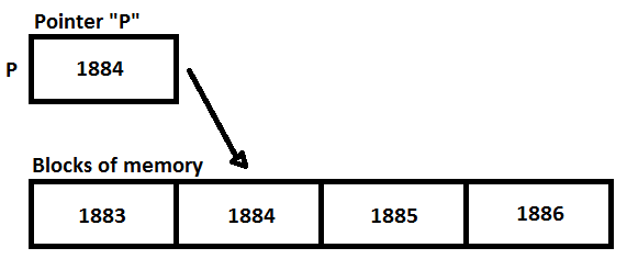
Any of you who have experience using C or C++ already have experience with pointers. We will be using the same thing here in the context of "lookup tables".
Lookup tables are another way of compactifying our code to make it shorter, more elegant, and easier to understand.
First lets write the code and then we will explain what is happening. First, at the top of our program we will have a section labeled "numbers:" followed by some ".db" assembler directives. These directives "define bytes" and what they do is they place those bytes sequentially in a certain section of "Program Memory" defined by the label numbers. So that when the hex code is loaded onto the microcontroller, a certain segment of the flash memory that stores all of the program instructions will contain these bytes one after the other in order.
numbers:
.db 0b01111111, 0b11011110, 0b01011110, 0b11010010
.db 0b01010010, 0b11000000
Then we can actually get these numbers anytime we want them since they will always be located at certain specified program memory locations. Remember how we dealt with interrupts? We placed an instruction at exactly 0x0020 in Program Memory. We knew that if a timer overflow interrupt occured the cpu would check that exact location and execute whatever command we put there. Well lookup tables work in a very similar way.
We are going to re-write our "dice:" labeled subroutine, which is the one that tells the microcontroller which pins to turn on to get which number on a die, so that instead of a long and ugly section of code, it can use a loop and do things more simply. Here is the new code:
dice:
   ldi ZH, high(2*numbers)
   ldi ZL, low(2*numbers)
   ldi temp,0
  check:
   inc temp       ; increment temp
   cp die1,temp   ; compare die1 with 1
   brne PC+2      ; if not equal don't set die1
   lpm die1,Z     ; load die1 with number 1
   cp die2,temp   ; compare die2 with 1
   brne PC+2      ; if not equal don't set die2
   lpm die2,Z     ; load die2 with number 1
   cpi temp,6     ; if temp 6 we're done
   breq PC+3      ; if equal go to ret
   adiw ZL,1      ; increment to next number
  rjmp check      ;   in lookup table
   ser temp       ; reset temp
ret
You see that it is much shorter. In fact, whenever you find yourself repeating the same set of instructions over and over inside a subroutine and the only thing different each time is that some particular number is different, that is a perfect time to use a lookup table. In the instances where you would use a "for loop" or a "switch-case" routine in C or some other language, that is a good time to use a lookup table in assembler.
Lookup tables have a reputation for being complicated but I don't think it is deserved. I will try to explain it in a simple way here.
Let us begin with the atmega328p memory map. There are three different types of memory available to store stuff. The "Program Memory" which stores our program, the "SRAM Data Memory" which contains all of the registers that we use like the general purpose working registers, the input output ports, and all of the registers that we use to toggle bit and control the way things are done, and finally the "EEPROM" memory, which we will be introducing in a later tutorial (if I last that long) and is used to store information that will not vanish when we turn off the power. Very useful if you are making a game and you want to store somebodies score until the next time they play!
We know that every byte of a given type of memory has an address. For example, the first byte of code we execute is at 0x0000 and the timer overflow interrupt handler is at 0x0020, etc. You will notice that since we have more than 256 bytes of memory in our Program Memory space we can't just use addresses 0x00 up to 0xFF. In fact, we have 32k of flash memory in the Program Memory space. This means we need addresses from 0x0000 up to 0x7FFF.
Now, suppose we want to read whatever is at a specific address in memory? For example, when the cpu gets an overflow interrupt it goes to 0x0020 and executes the instruction we placed there. What if we want to place instructions or data or whatever at some specific address in Program Memory and then use that in our program? We can, except that our general purpose registers can only hold 8 bits (1 byte) between 0x00 and 0xFF, and as we have seen, an address takes 2 bytes to write down (between 0x0000 and 0x7FFF). So there is not enough room in a general purpose register (i.e. a variable like r16) to hold a Program Memory address. We can't say "ldi r16, 0b0000000000000010" for example, since R16 isn't big enough. So if we have no way of storing the full address how can we go there during the program? We can just pick up the phone, call the cpu, and say "can you go and execute what we stored at 0x2a7f please" you have to have that address in an r16 or something and then "mov" it or "out" it from there.
So here is what the ATmel folks have done to solve this dilemma. They have dual purposed a few of our general purpose registers. In particular, if you look at table 7-2 on page 12 of the datasheet, you can see how the general purpose registers are organised. The registers r26, r27, r28, r29, r30, and r31 can also be combined into pairs called X, Y and Z. So that X is r26 and r27 together, Y is r28 and r29 together, and Z is r30 and r31 together. That way if we take Z for example, the first half of it is r30 and the second half of it is r31. So if we want to store a Program Memory address we just store half of it in r30 and the other half of it in r31 and then we tell the cpu to look up Z if we want to talk about the whole thing together. They have implemented two instructions that do this. The first is spm which stands for "Store Program Memory" and the other is lpm which stands for "Load Program Memory". So now if we want to get what ever instruction or data is stored at memory address 0x24c8 for example, we would put that address in r30 and r31 and then when we want to get the data we would just lpm it to a variable by doing
lpm r16,Z
which will go to memory address Z, take whatever data we put there, and stick it in r16. The cool thing about this is that if we add 1 to Z using
adiw Z,1
then Z will now "point to" the next memory address after the first one. So that if we stick a whole list of numbers in memory one after the other we can cycle through them by incrementing Z.
How did we use this in our program?
Well, since each number on the dice is displayed by turning on and off various ports like PC2 and PB5 we just store the number that does that for each number on the die. For example if we "out" 0b11010010 to PortC it will set PC0 to 0, PB1 to 1, etc and turn on the corresponding LEDs to give us our number on the die. In this case the number 4.
So we will use a "lookup table" called "numbers:" to store all of these different die configurations and simplify our code.
I think if you read the code above, and look up the various instructions in the instruction manual, you can easily figure out how it works. The only weird part is the first bit where we initialize the pointer Z.
ldi ZH, high(2*numbers)
ldi ZL, low(2*numbers)
What this does is initializes the pointer Z to point to our list labeled "numbers". The reason for the 2 times in front is that we want the address of "numbers" shifted to the left one space (that is what times by two does to binary numbers). This leaves free the far right bit (the least significant bit) which is then used to decide which byte of Program memory we are referring to. This is because Program Memory is 2 bytes (16 bits) wide. So for example, in our lookup table we have first two numbers as
.db 0b01111111, 0b11011110
Since the Program Memory space is 16 bits wide both of these numbers will actually be sitting at the same Program Memory address so the way we grab the first one or the second one is why we need the "times by 2" or left shift of the bits. When the "Least significant bit" of Z is a 0 it will point to the first one of our list: 0b01111111, and when the least significant bit of Z is a 1 it will point to the second one of our list: 0b11011110.
As you can see, adding 1 to Z changes the least significant bit from a 0 to a 1 and then adding 1 to Z again increments the Program Memory address and the LSB goes back to a zero. So you see that it works great for picking out our entire list of stored numbers one at a time by simply incrementing Z.
Notice that when we shift the address of "numbers" left by multiplying by 2 to free up the least significant bit to use for selecting the first or second byte stored at that address we are losing the "most significant bit" of the address. This means that we can only store our lookup table data in addresses where the most significant bit doesn't matter - i.e. all of our named data will have the same most significant bit. This means our address is effectively 15 bits long. 2^15 is 32768 different addresses available for our stored data. We are going to look at this in more detail in the next tutorial so don't worry if it is a bit confusing at this point.
Now you know how to use lookup tables and the X, Y, and Z pointers to simplify your code writing.
Let's now give the complete program with these innovations included.
Final Version of the Code
;********************************
; written by: 1o_o7
; date: <2014|11|02>
; version: 2.0
; file saved as: paradise2.asm
; for AVR: atmega328p
; clock frequency: 16MHz
;********************************

; Program funcion:---------------
;
; A dice roller
;
; LEDs on PC0 through 5
; and the center one on PB1
; Button on PB0
; anodes on PB4 and PB5
;
; Added Macro's and lookup tables
;
;--------------------------------

.nolist
.include "./m328Pdef.inc"
.list

;=================
; Declarations:

.def temp         = r16
.def overflows    = r17
.def die1         = r18
.def die2         = r19
.def milliseconds = r20
.def seed         = r21

.macro delay
   clr overflows
   ldi milliseconds,@0
  sec_count:
   cpse overflows, milliseconds
  rjmp sec_count
.endmacro

;=================
; Start of Program

.org 0x0000
rjmp Reset            ; rjmp takes 2 cycles, jmp takes 3
.org 0x0020           ; Timer0 overflow handler
rjmp overflow_handler

numbers:
.db 0b01111111, 0b11011110, 0b01011110, 0b11010010
.db 0b01010010, 0b11000000

;=================

Reset:
   ldi temp,0b00000011
   out TCCR0B,temp     ; TCNT0 in FCPU/64 mode, 2500000 cnts/sec
   ldi temp,249
   out OCR0A, temp     ; top of counter so 250 counts/overflow
                       ;   so overflow occurs every 1/1000 sec
                       ;   this means an overflow every 1ms
   ldi temp,0b00000010
   out TCCR0A,temp     ; reset TCNT0 at top of OCR0A
   sts TIMSK0, temp    ; Enable Timer Overflow Interrupts
   sei                 ; enable global interrupts

   ldi temp,0b11111110
   out DDRB,temp       ; PB0 input the rest output
   ldi temp,0b11111111
   out DDRC,temp       ; PortC all output

main:
  ser temp
  out PORTB,temp      ; all PortB at 5V
  out PORTC,temp      ; all PortC at 5V
  rcall button_push   ; wait for button
  rcall random        ; get rand nums die1, die2
  rcall dice          ; set up dice LEDs
  ser temp            ; set temp for carry
  rcall cycle         ; animate dice throw
  rcall display       ; display the result
rjmp main

button_push:
   sbic PINB,0        ; skip if PB0 is GND
   rjmp button_push
ret

random:
         ; attempt to generate random numbers
   add die1,seed
   swap seed
   delay 37
   add die2,seed
   clc
  d1:
   cpi die1,6   ; compare die1 with 5
   brlo d2      ; if die1 < 6 then roll
   subi die1,6  ; else subtract 6
   rjmp d1      ; go back and compare again
  d2:
   cpi die2,6   ; compare die2 with 6
   brlo roll    ; if die < 6 then roll
   subi die2,6  ; else subtract 6
   rjmp d2      ; go back and compare again
  roll:
   inc die1     ; add 1 so between 1 and 6
   inc die2
ret

dice:
   ldi ZH, high(2*numbers)
   ldi ZL, low(2*numbers)
   ldi temp,0
  check:
   inc temp       ; increment temp
   cp die1,temp   ; compare die1 with 1
   brne PC+2      ; if not equal don't set die1
   lpm die1,Z     ; load die1 with number 1
   cp die2,temp   ; compare die2 with 1
   brne PC+2      ; if not equal don't set die2
   lpm die2,Z     ; load die2 with number 1
   cpi temp,6     ; if temp 6 we're done
   breq PC+3      ; if equal go to ret
   adiw ZL,1      ; increment to next number
  rjmp check      ;   in lookup table
   ser temp       ; reset temp
ret

cycle:
   rol temp       ; shift bits left with wrap around
   delay 50
   sec            ; set SREG carry flag
   out PORTC,temp ; PortC starts as 0b11111110
   sbrc temp,6    ; skip if bit 6 is cleared
   rjmp cycle     ; otherwise loop back up
ret

display:
   sbi PORTB,0     ; set button to off
   sbi PORTB,1     ; turn off center led
   sbi PORTB,4     ; turn on die1
   cbi PORTB,5     ; turn off die2
   sbrs die1,7     ; skip if center led off
   cbi PORTB,1     ; turn on center led if needed
   out PORTC,die1  ; turn on the others
   delay 2         ; short delay
   sbi PORTB,1     ; turn off center led
   cbi PORTB,4     ; turn off die1
   sbi PORTB,5     ; turn on die2
   sbrs die2,7     ; skip if center led off
   cbi PORTB,1     ; turn on center led if needed
   out PORTC,die2  ; turn on the others
   delay 2         ; short delay
   sbic PINB,0     ; exit to main if button press
   rjmp display    ; loop to the top
ret

overflow_handler:
   inc overflows   ; increment 1000 times/sec
   add seed,overflows
reti
Random Number Generators
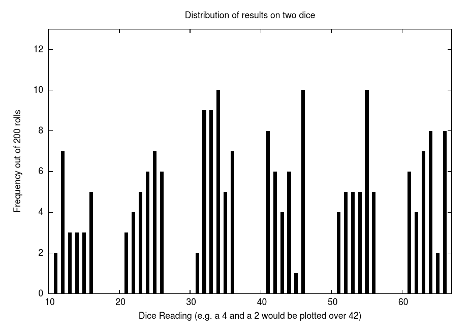
If you examine the section of the program labeled "random:" you will see the method I used to get random numbers to put on the dice. I just invented this on the fly and it is definitely not the best method of getting random numbers. The problem of getting truly random numbers out of a computer is a difficult one. The way most people do it is similar to the way I did: you use the people using the program to generate the random number. I used the time it takes you to push the button to get a "seed" for my random number since it is difficult for you to take "exactly" the same amount of time to push the button each time. Since the cpu oscillates 16 million times a second it is unlikely you can push the button at exactly the same TCNT0 number each time (even though that is only between 0 and 249) once I get that number and store it as a variable called "seed" I use it to generate two pseudo-random numbers, one for each of the dice. As you can see by the above graph that I made by counting how many times each different roll came up during 200 rolls, they are not all that random (for example a 4 and a 5 doesn't come up very often comparatively -- as can be seen by the graph, it only came up once in 200 rolls), but it is not too bad for a first attempt!
Exercise 3: Figure out how random our dice are by pushing a bunch of times and graphing the results. What percentage of the time do you get each digit on a given die? Is a certain number coming up more often in the long run? If so, then it is not truly random. If vegas coded their video slots with this generator and you did the same graphing analysis you could make a million bucks. (and I expect a piece of the action for pointing it out haha)
Exercise 4: Do some explorations and studies to find a better random number generator to implement in this code.
Conclusion

I hope you enjoyed constructing this circuit and implementing this code and I hope you learned more about programming methods and how to use some of the special features like
- subroutines
- macros
- lookup tables
- random number generators
- controlling multiple LEDs with the same wire
Exercise 5: Why did we set the SREG carry flag after the delay in the cycle subroutine?
Exercise 6: The most important exercise in this tutorial is to go through the various subroutines in the code and figure out how they accomplish their goal. Understand the commands and what the processor is doing when it encounters various branches. How are the random numbers being generated? How are the correct LEDs being turned on and off?
At this point you should already be well prepared to write many different assembly programs to control many interesting electronics devices. There are still a lot of things to learn but you now have a handle on some of the most important tools. In the next tutorial we will be looking a bit closer at the way things are stored in the Program Memory.
Thanks for reading and hope to see you next time!