Color Sensor

Description:
Color Sensor Module is a complete colour detector, including a 4 white LEDs and TAOS TCS3200 RGB sensor chip. The four white LED’s to provide a broad spectrum light source .The TCS230 has an 8 x 8 array of photodiodes with color filters (16 Red, 16 Blue, 16 Green, 16 Clear). A light to frequency converter generates a 50% duty cycle square wave on the output pin. Frequency is directly proportional to light intensity. Output scaling 100%, 20% and 2% allows for wide dynamic range of intensities. The color selects (S2, S3), frequency scale (S0, S1) and output are TTL logic level and can be connected directly to the micro controller. Basic readings are easy using the Arduino “pulsein” command. Take a reading for each color. The reading with narrowest pulse width or highest frequency is the major color.
Features:
- Single-Supply Operation (2.7V to 5.5V)
- High-Resolution Conversion of Light Intensity to Frequency
- Programmable Color and Full-Scale Output Frequency
- Power Down Feature
- Communicates Directly to Microcontroller/Arduino
- S0~S1: Output frequency scaling selection inputs
- S2~S3: Photodiode type selection inputs
- OUT Pin: Output frequency
- EO Pin: Output frequency enable pin (active low)
Material Planning


For this tutorial, the items needed to run this project are:
- Arduino Uno
- USB Cable type A to B
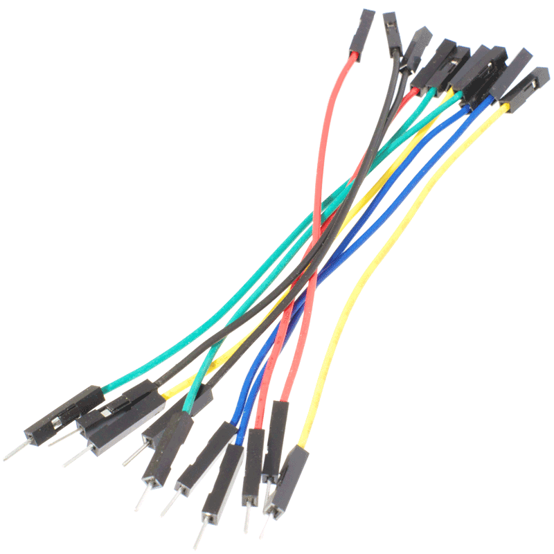
- Female to male jumper wire
- Male to male jumper wire
- LED (Red, Green and Blue)
- 470 ohm
Hardware Installation


Diagram above shows the simple connection between Color Sensor and Arduino UNO:
- vcc > 5v
- GND > GND
- SO > D3
- S1 > D4
- S2 > D5
- S3 > D6
- OUT > D2
Connection between LED and Arduino UNO:
- Red LED > D8
- Green LED > D9
- Blue LED > D10
After completing the connection, connect the Arduino to power supply with USB cable.
Insert Source Code
- Download the test code and open it by using Arduino software or IDE.
- Make sure that you have choose the right board and the corresponding port. (In this tutorial, Arduino Uno is used)
- Then, upload the test code into your Arduino Uno.
Downloads
Result


When the color sensor is towards the red color, the Red LED will ON. Same like Green LED and Blue LED it will ON when the color sensor is towards to the color.
Video

Enjoy watch the tutorial!