Color Sensing Robot
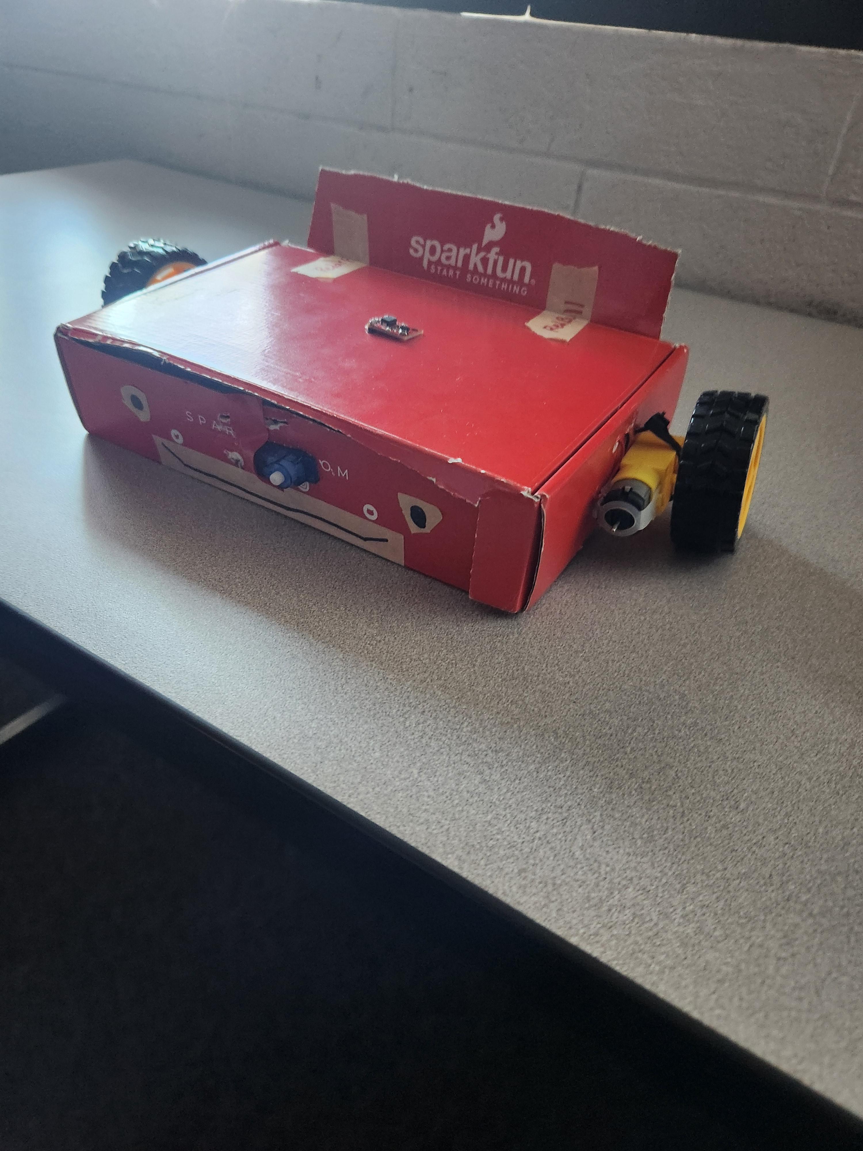
This instructable will show you how to build a robotic car that draws a certain shape based off of the color it senses. We used the Sparkfun tool kit box as the body, and the majority of the parts of the car are from the Sparkfun tool kit except for the color sensor. We tried to make the building part as easy as possible because understanding the code is somewhat difficult, but everything is very doable. Enjoy!
Supplies
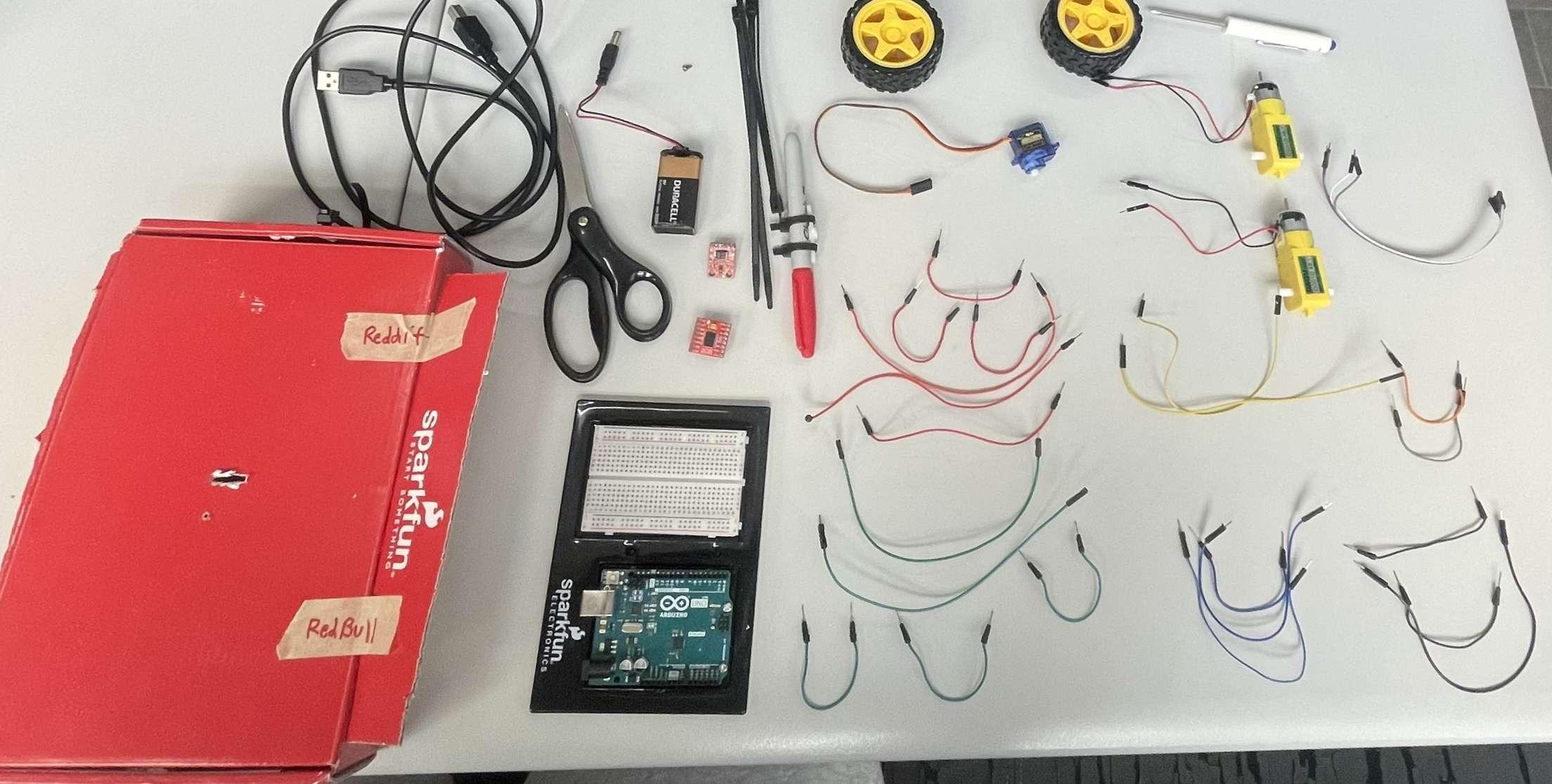
You will need the SparkFun inventors kit v4.1
All supplies needed:
- 1 Arduino Uno
- 1 Small Breadboard
- 1 Motor Driver
- 1 Medium Cardboard Box/ SparkFun Box
- 1 Marker
- 1 Servo Motor
- 1 large sheet of paper
- 2 Hobby Gearmotors
- 2 Wheels
- 1 Battery Pack
- 4 AA Batteries
- 22 Wires
- 5 zipties
Create TinkerCAD Circuit and Code
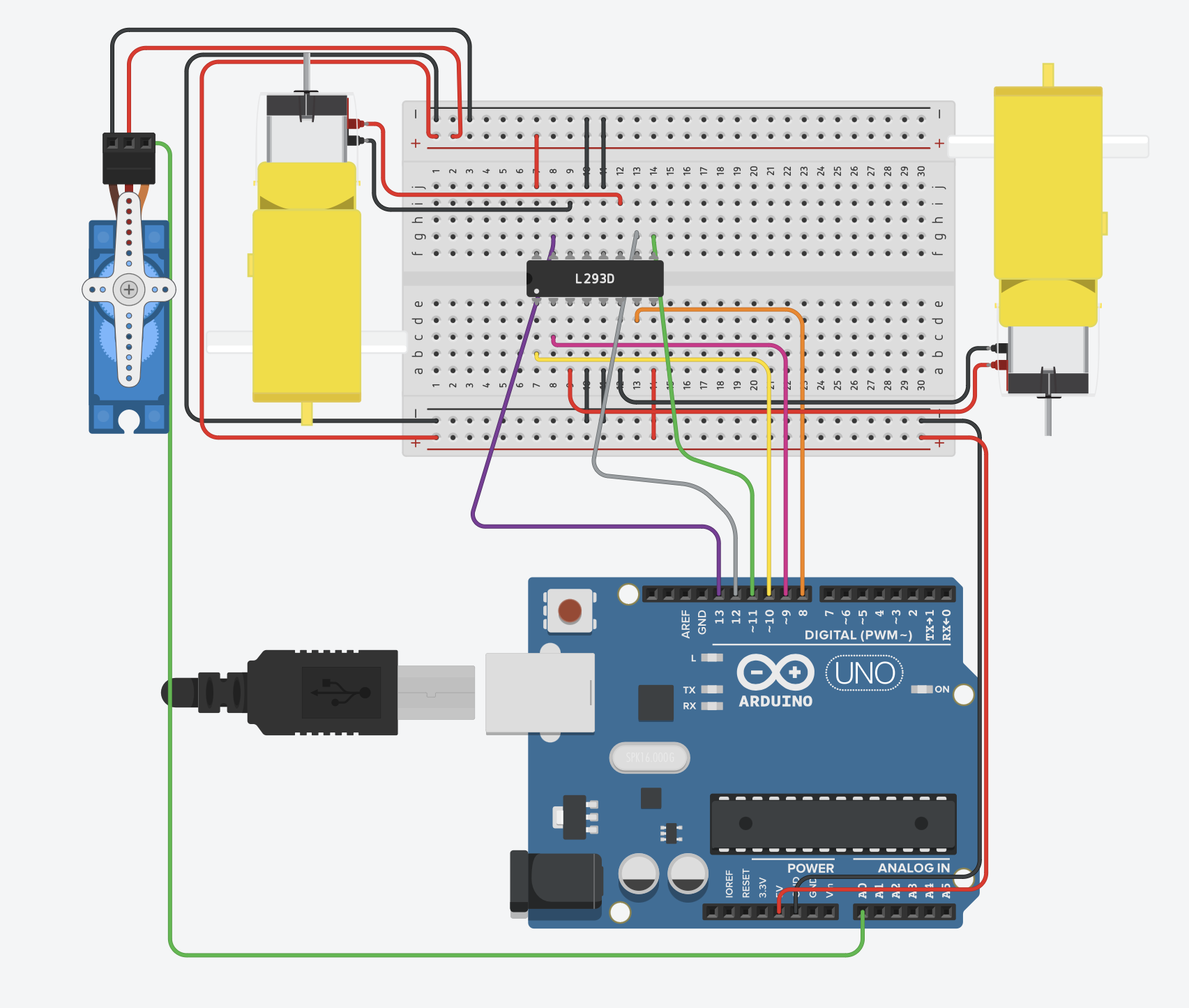
- Create the wiring on the TinkerCAD website and wire the board to look like the photo above.
- Write the code as it follows in the attachment below.
The video below explains how the code works.
Downloads
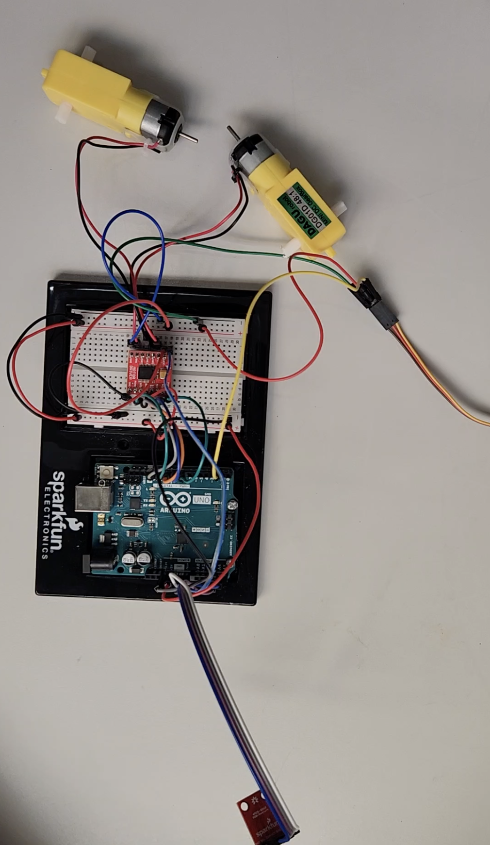
Wiring
Tools needed
- Breadboard
- Arduino Uno
- Motor Driver
- 4 wires
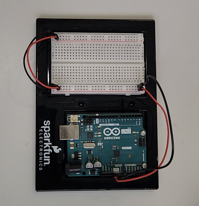
First, we need to form a connection from the breadboard to the Arduino Uno
- Positive supplies power, connect to 5v
- Negative connects to ground (GND)
- Then connect the positive on one side of the breadboard to the other side
- Do the same with the negative
- Add the motor driver to the Breadboard as shown
- Connect PWMA to 11 on the Arduino Uno using a wire
- Connect AIN2 to 12 on the Arduino Uno
- Connect AIN1 to 13 on the Arduino Uno
- Connect BIN1 to 10 on the Arduino Uno
- Connect BIN2 to 9 on the Arduino Uno
- Connect PWMB to 10 on the Arduino Uno
- Using a red wire connect STBY to positive on the breadboard
- Using a black wire GND to negative on the breadboard
- Connect VM to VIN on the Arduino Uno
- Connect VCC to positive on the breadboard
- And finally connect both of the GND on the top of the motor driver to negative on the breadboard
- Connect the red wire of the first Hobby Gearmotor to A01 on the motor driver
- Connect the black wire of the first Hobby Gearmotor to A02 on the motor driver
- Connect the red wire of the second Hobby Gearmotor to B01 on the motor driver
- Connect the red wire of the second Hobby Gearmotor to B02 on the motor driver
Servo Motor
- Connect the left pin (Ground) on the Servo Motor to negative on the Breadboard using a black wire
- Connect the middle pin (Power) on the Servo Motor to positive on the Breadboard using a red wire
- Connect the right pin (Signal) on the Servo Motor to A0 on the Arduino Uno using a colored wire
Color Sensor
- The color sensor has 6 pins but for this project we are only using the inner 4
- First connect the GND pin to GND on the Arduino Uno
- Then connect the VCC pin to 3.3V on the Arduino Uno
- Next connect the SDA pin to A4 on the Arduino Uno
- Finally connect the SCL pin to A5 on the Arduino Uno
Full wiring video below
l l l l l
v v v v v
Create Chassis
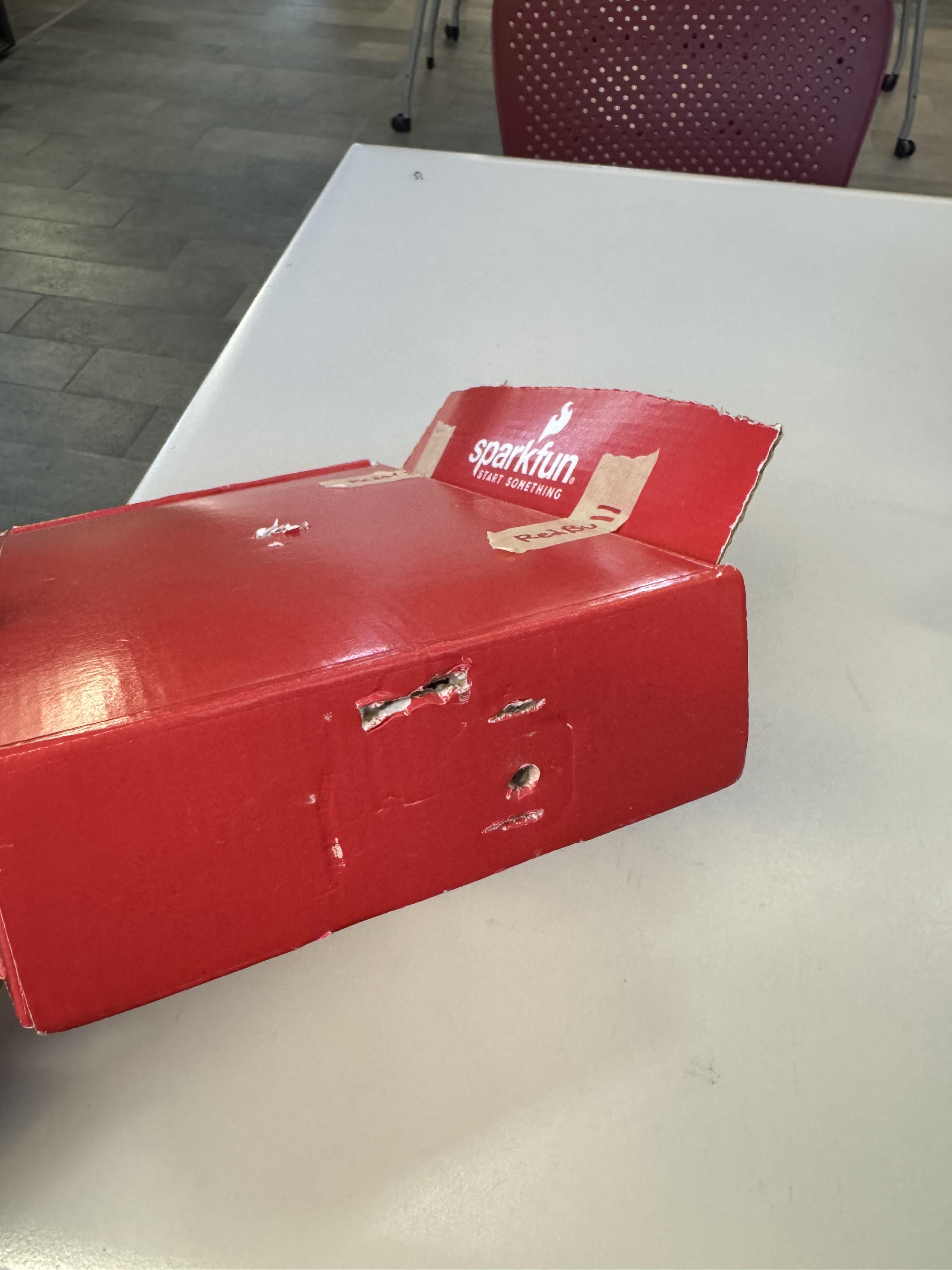

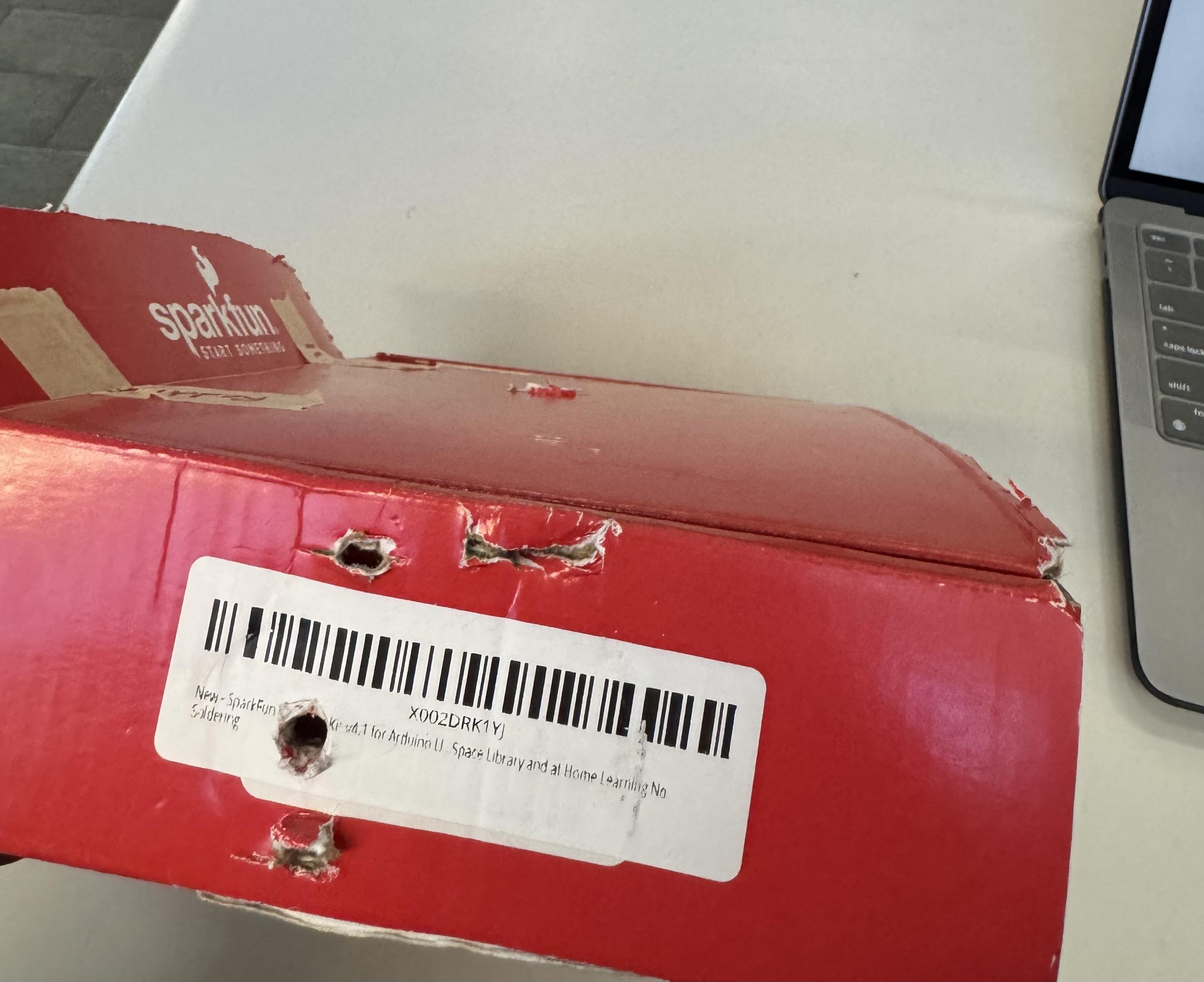
- Make sure Sparkfun kit box is empty and open. And cut a rectangular piece from the front of the box like it's shown in the photo under the Introduction.
- Make two horizontal slits on both short ends of the box. One towards the top and one towards the bottom and make sure the slits are directly across from each other as these will be used to tie the two Hobby Gearmotors to each side of the box. Cut small holes on both of these sides small enough to slide the wiring for each gearmotor through.
- Also make two horizontal slits in the top and bottom of the center of the front part of the box, and cut a rectangular side hole between the two slits that way the gear motor can slide in from the inside of the box.
- Cut another rectangular hole in the center of the top of the box big enough to slide the color sensor in place as well as the wiring for it.
- To add a fun element, use the rectangular cut out from part 1 as a spoiler for this car by taping it to the back of the box.
The video below describes the cuts in the chassis and the wiring.
Put Everything Together
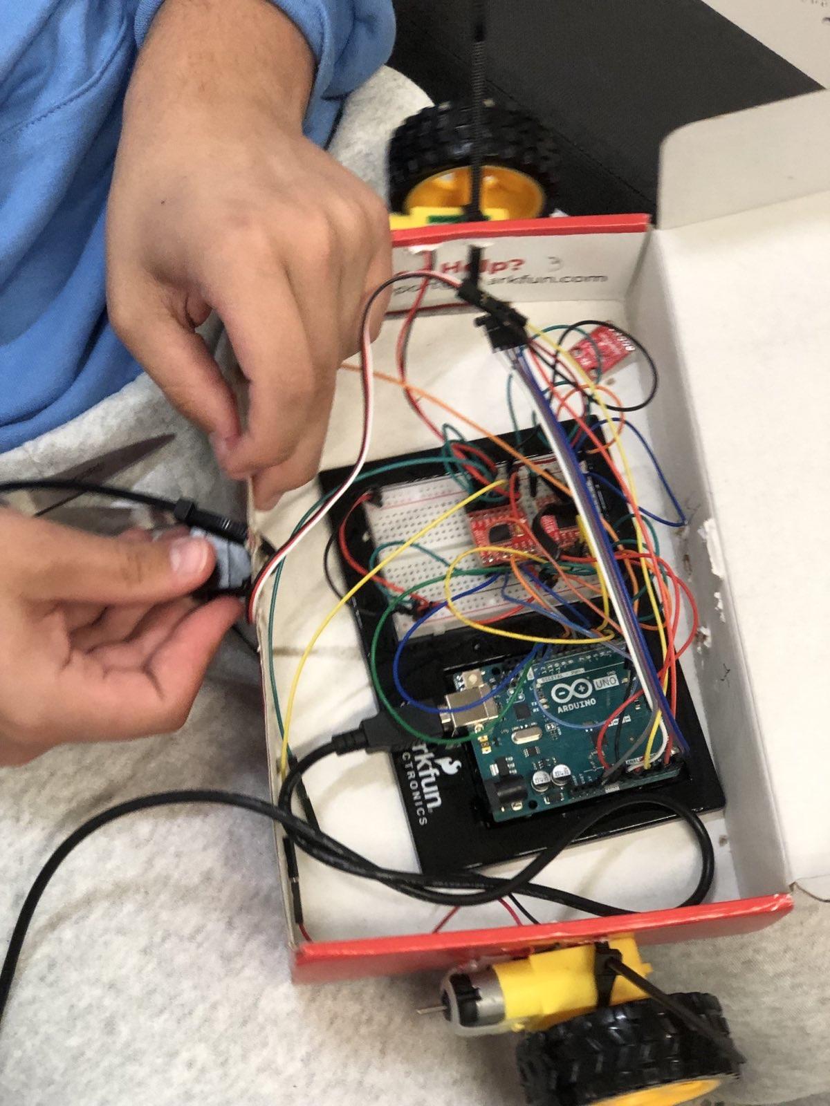
- Unplug the wiring for the gearmotors, the servo motor and the color sensor and place everything else inside the box inclusing the battery pack
- Thread the wiring for the two gearmotors through the small holes you made on each side of the box. Then use a zip tie to attach the gearmotors to each side of the box by threading it through the two slits you made on either side.
- Thread the wiring for the color sensor through the hole you made on the top of the box and secure the color sensor to the top of the box.
- Slide the servo motor and its wiring through the hole you made on the front part of the box and use the two slits you made two secure it in place with a zip tie. Also zip tie the marker to the
- Reconnect all the wires back to the board, then close the box.
Watch the video below to see how to put everything together.
GO TIME!!
- Get a piece of paper at least 4x4 ft and place it on the ground securing it on each corner.
- Make sure the battery pack is plugged in and the code is uploaded to the robot through Arduino, then place it in the center of the paper.
- Use your phone and get a blue, green and red picture.
- Place the phone with either of the photos over the color sensor and let the robot do its thing!
Below are 3 videos showing the robot creating the triangle, square and circle without the marker.