Color Mixing Lamp Arduino Project Instructable
by JacSal in Circuits > Arduino
3574 Views, 19 Favorites, 0 Comments
Color Mixing Lamp Arduino Project Instructable
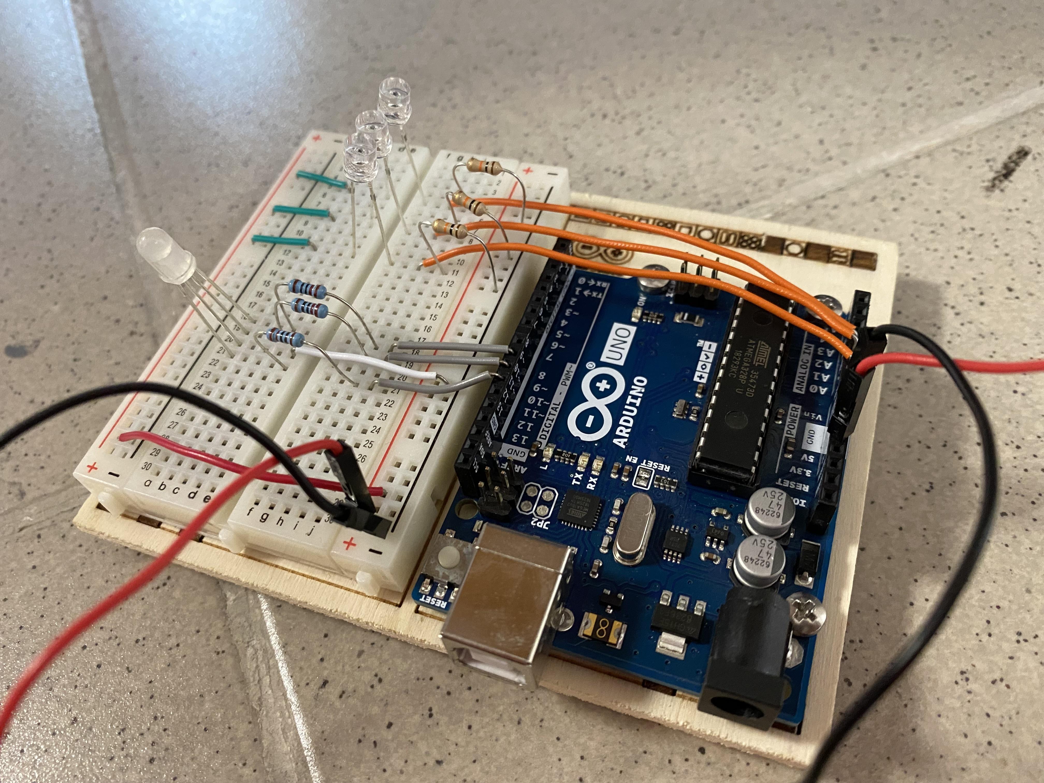
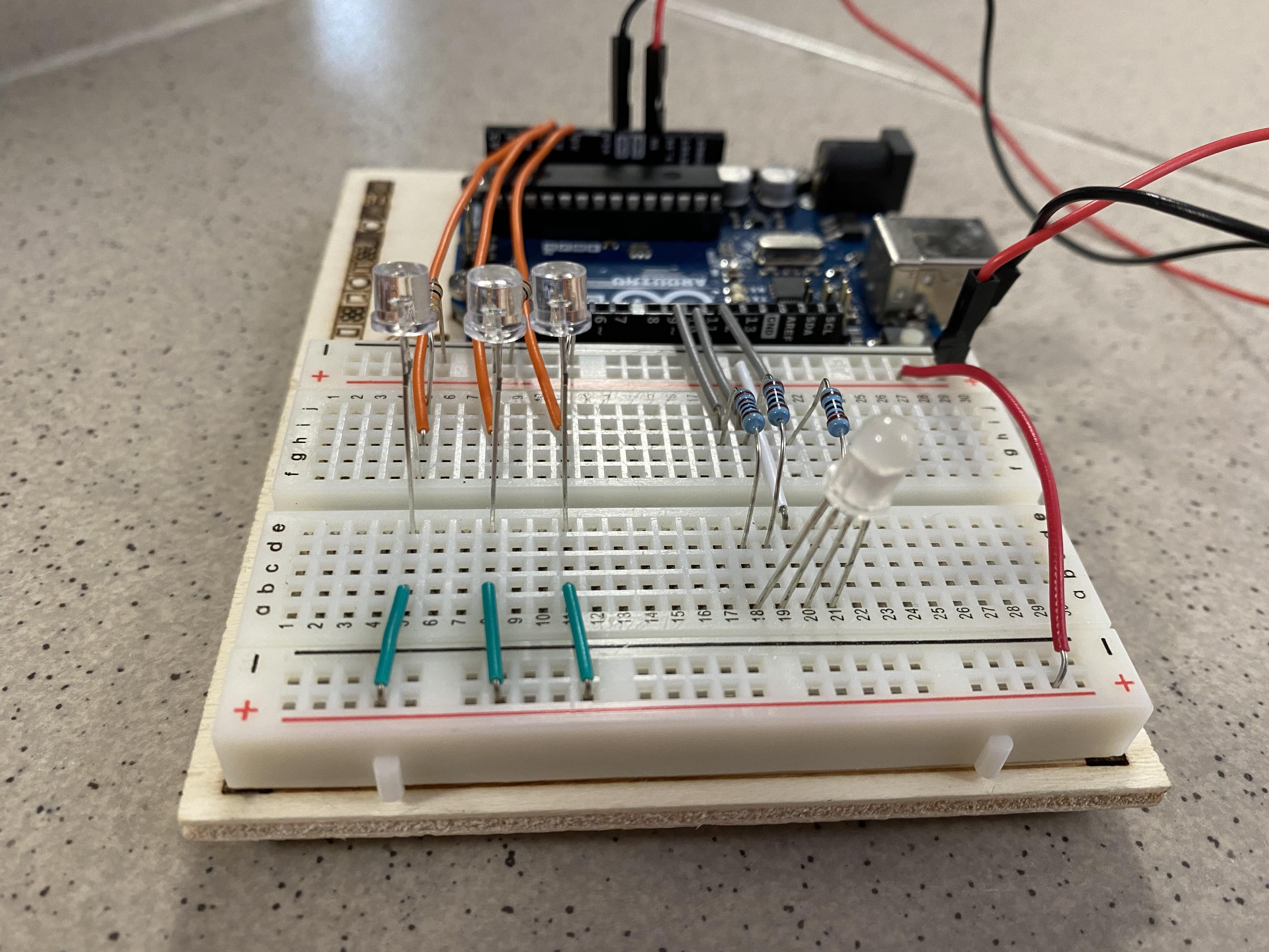
This is the Color Mixing Lamp from the Arduino Projects Book (Project 4). The project will sense the light conditions around the phototransistor and create different color lights.
Supplies
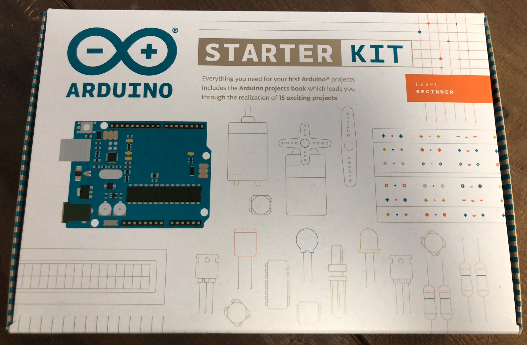
You will need the Beginner Arduino Starter Kit, either Windows, Mac OS, or Linux on a device to download the Arduino Software.
Download the Arduino Software
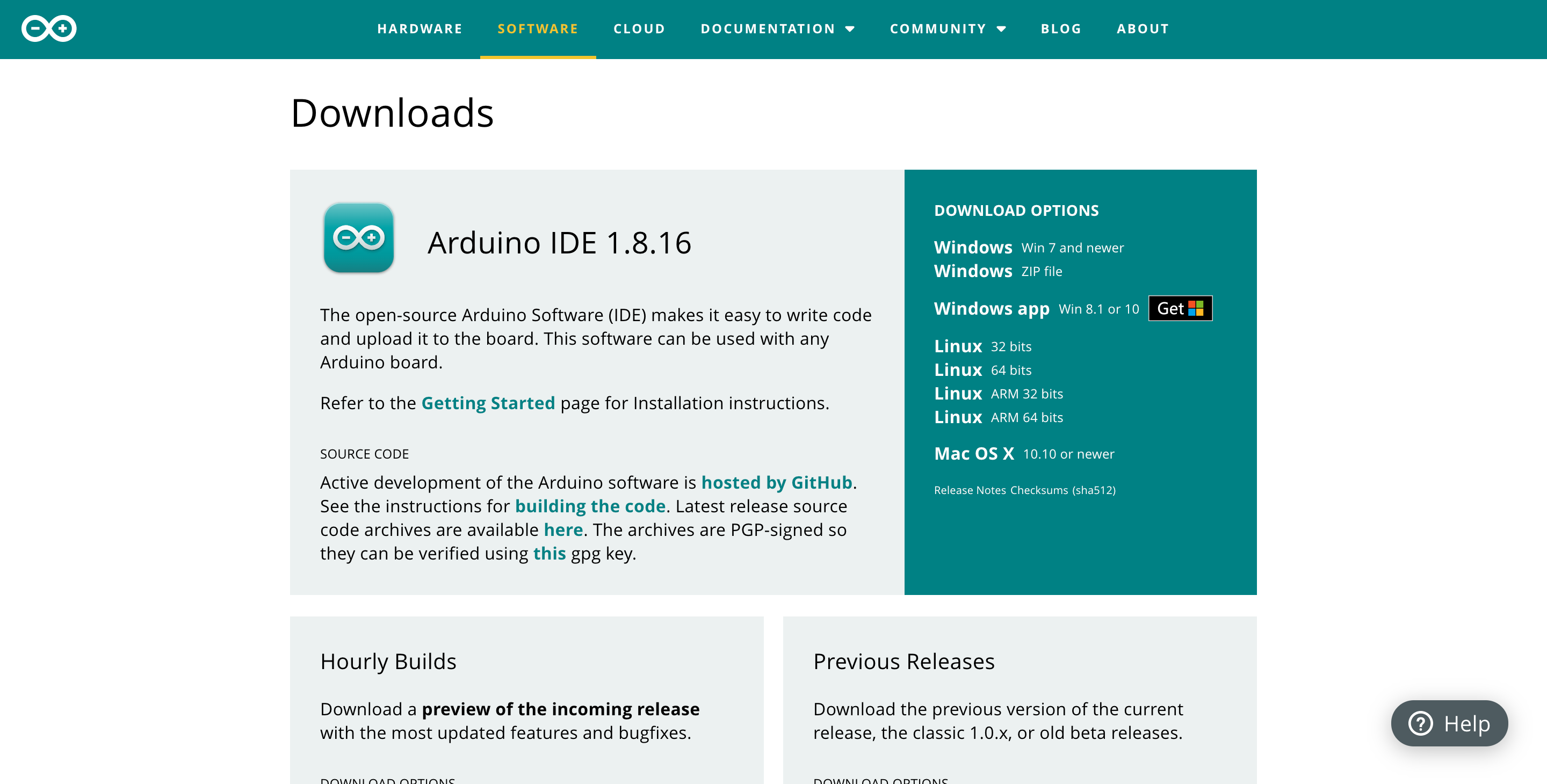
- Go to https://www.arduino.cc/en/software and download the software applicable to your device.
- Once you have downloaded the right software follow the instructions in the Project Book included in the Arduino Starter Kit on pages 15-17
Gather All the Components
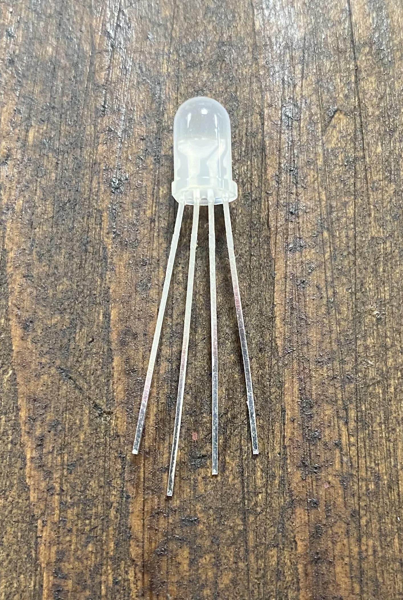
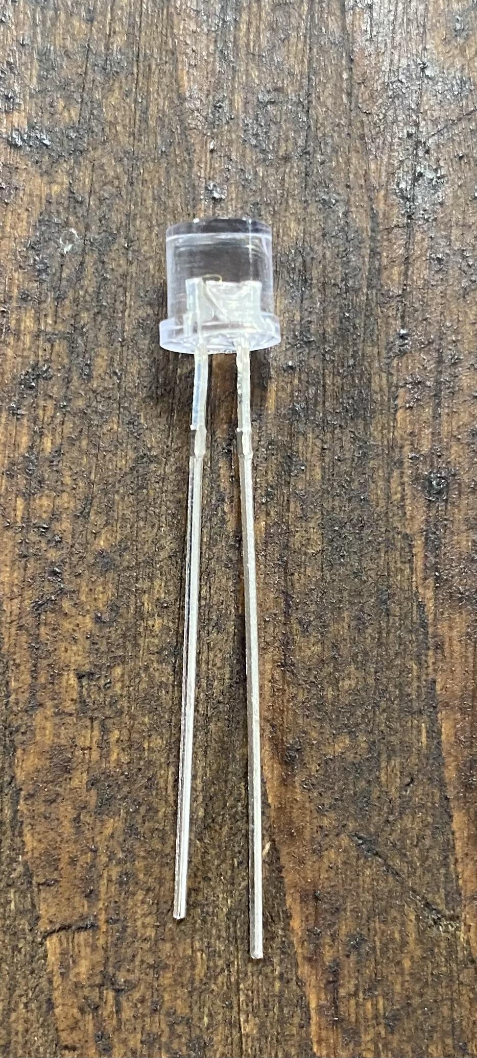
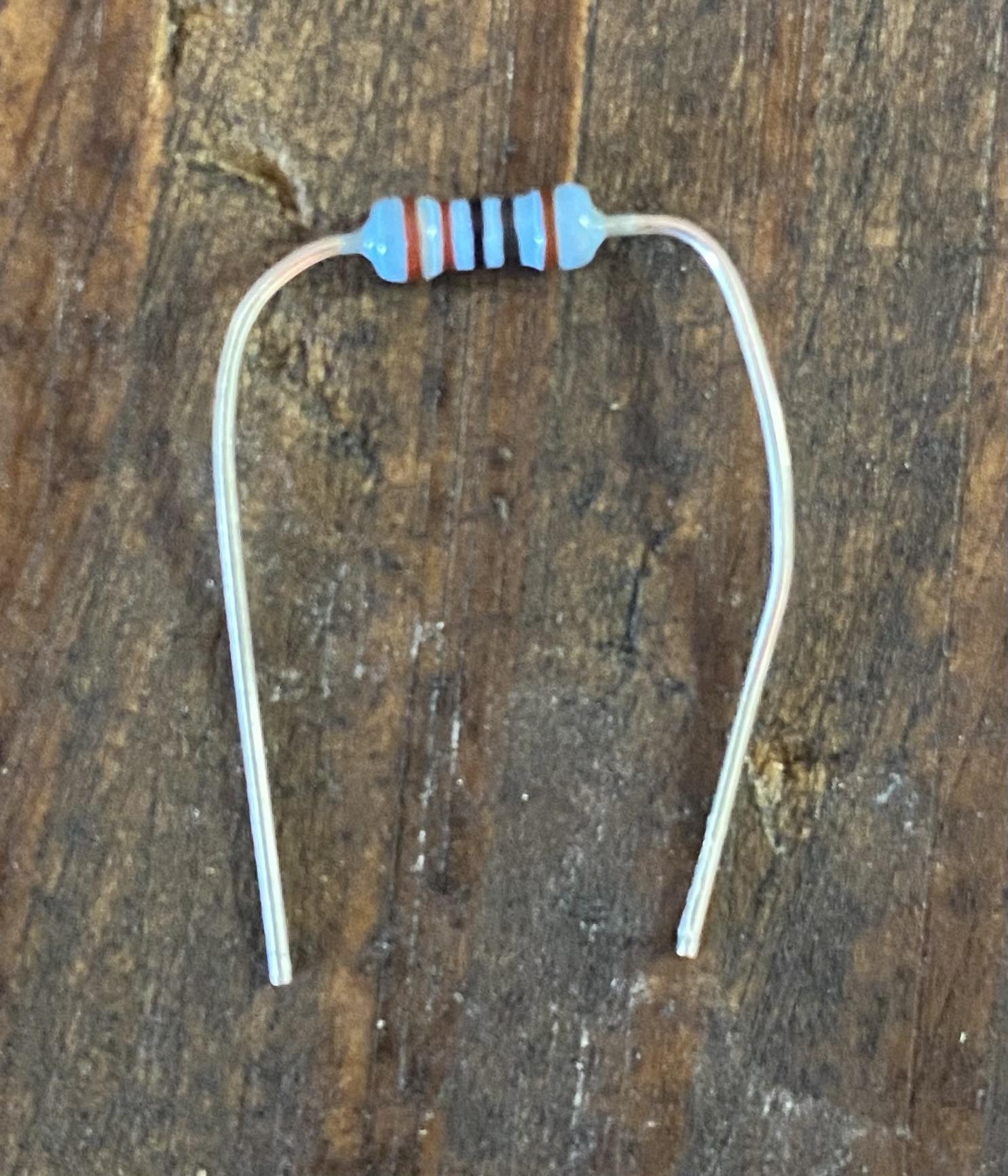
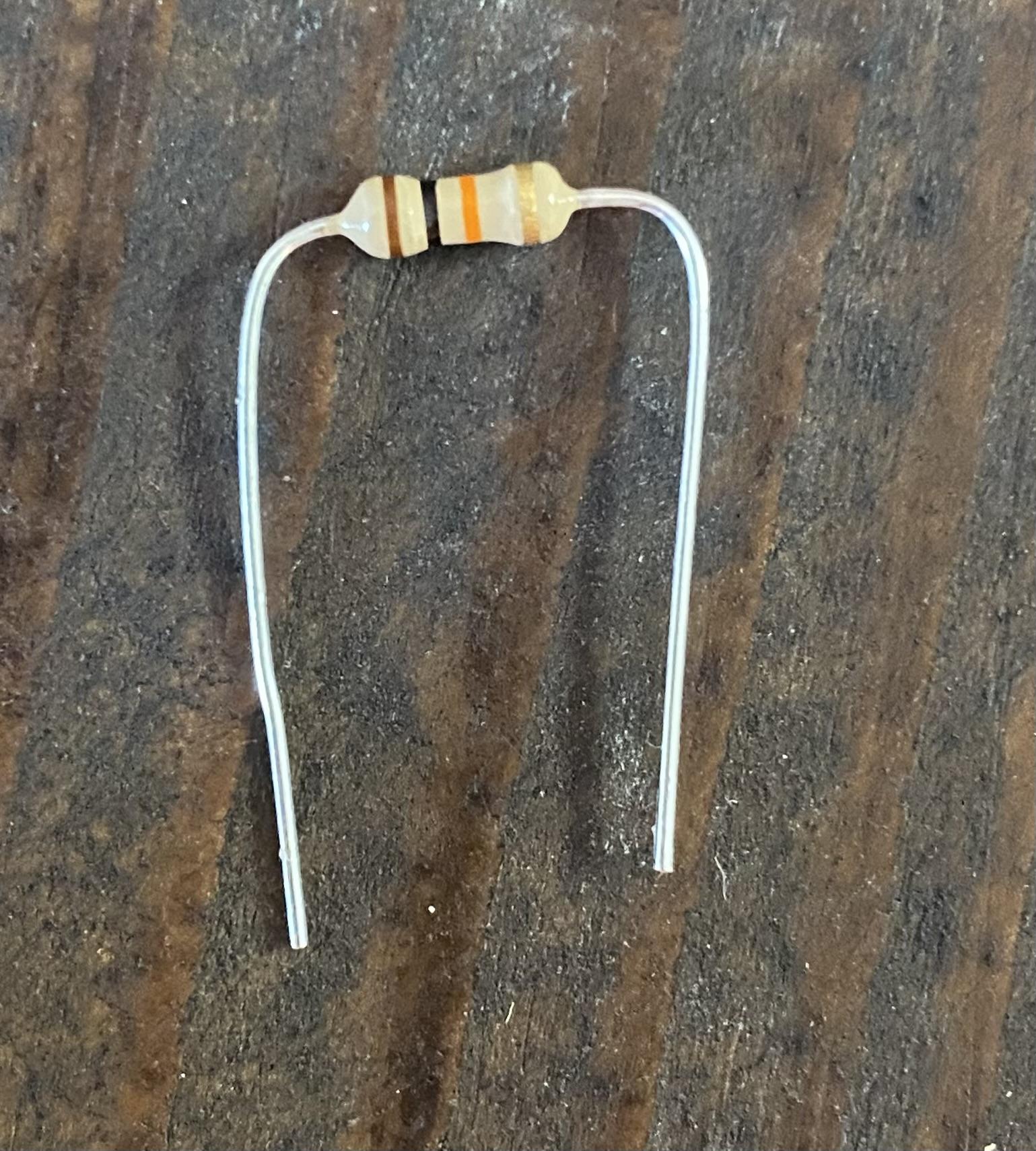
All materials are in the Arduino Starter Kit. The components you will need are,
- 3 220 OHM resistor (blue)
- 3 10 KILOHM resistor (tan with brown, black, orange, gold)
- 3 phototransistor
- Different color gel strips. (small translucent colored strips)
- LED with 4 legs
- 3 grey or blue or green wires (they are all in the same packet);
- 3 yellow or blue or green wires (they are all in the same packet);
- 1 white wire
- 3 orange wires;
- 1 red wire.
Build the Circuit
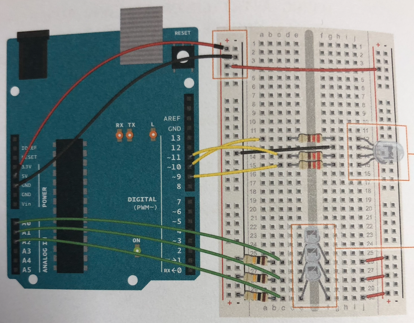
First, you want to make sure your Arduino is set up, use pages 12-13 to build the Arduino board.
Next, you want to assemble the circuit on the board using the picture above or page 54 in the book as a guide.
Building the circuit requires a lot of attention. Here are some pointers so that you don't get lost:
- The red wire connects power from one side to the other so there is power on both sides.
- It doesn't matter which number you connect your wire to as long as you also change the number when coding.
- The 220 OHM resistors are all positioned after the wires.
- The leg wire that connects the LED to the ground is the longest one (it is the negative end).
- The 10 KILOHM resistors are all positioned before the wires.
- The longest leg on the photoresistors is positively charged, so it needs to be connected to power, and the shortest one is negatively charged, so it needs to be connected to ground.
Note: If in doubt ask the teacher.
Type the Code
After you build the circuit you need to type up the code. Start by creating a new Arduino file. Then you want to copy down the code in the steps below. Each step has an explanation of that given section of code.
Coding Part 1

This part of the code creates new constant integers to use in the rest of the code. The "const int' is to enter the data, the "()LEDPin" is the name of the variable, and the "(number)" is to show which pin it is connected to.
Coding Part 2

This shows the value that each LED has, which in this case, it is equal to 0.
Coding Part 3

In "void setup()", the serial monitor will start to record the data at 9600 bps.
The mode of the LED pins was classified as OUTPUT.
Coding Part 4

In "void loop()", we read the value the sensors are transmitting and put a small delay between them.
Coding Part 5

After that, we set the serial monitor to print the values the sensors are transmitting, and add them in a sentence using the "\t" as the space in which the value will show. (note: don't forget the "ln" after the last line!)
Coding Part 6

Here we set the values the LED will transmit. The amount of red, green, and blue will change as you adjust the numbers.
Coding Part 7

This part shows how we are setting the serial monitor to print the value we set for the variables in the last step. (note: don't forget the "ln" after the last line again!)
Coding Part 8

The "analogWrite" commands the LED to output the values by emitting light.
Plug It in and See If It Works
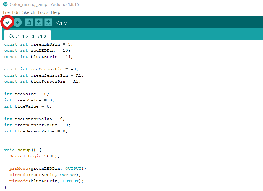
The first thing you need to do is to check if it works is to verify the code. You can do this by clicking the check button as shown in the first image. There may be many things wrong with your code. That is normal. You are most likely going to mess up. The only thing you can do is to check over everything to make sure you copied the code correctly.
Once it says everything is correct you need to plug in your computer to the Arduino via the cable supplied in the kit (the one with the USB end).
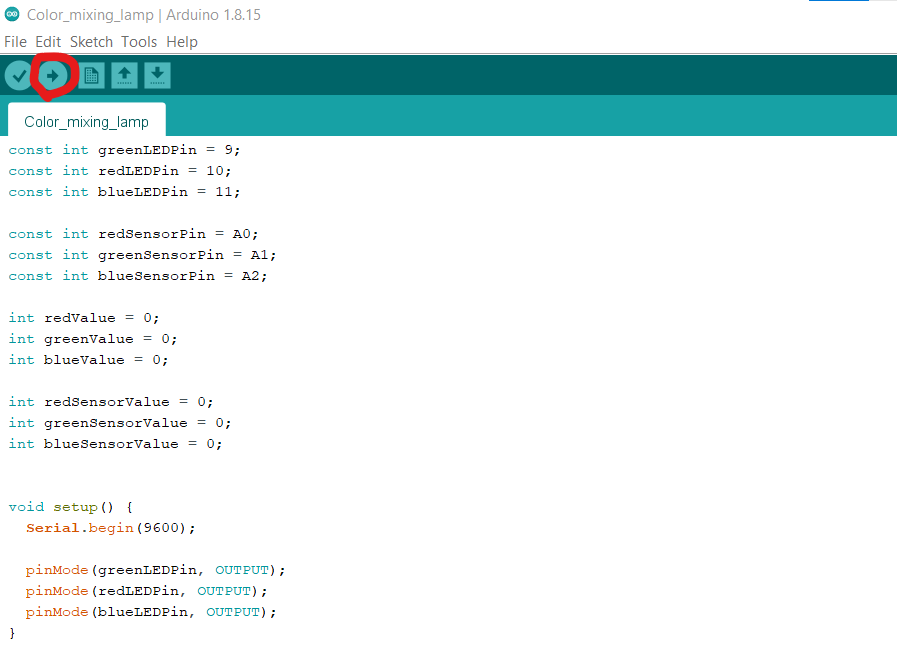
When you have everything connected click the upload button shown in the second image. After a few seconds, it should begin to work. If it doesn't work that's okay. It probably won't work the first time. Again as said in the text above the only thing you can do is to check everything, from the code to the wiring itself. If you can't get it to work ask for a teacher or peer to look at it as a fresh set of eyes will always help.
A video of the project working is attached below. Enjoy :D