Collision Avoidance System Using Arduino Uno
by Sarik Naveeth S in Circuits > Arduino
5575 Views, 1 Favorites, 0 Comments
Collision Avoidance System Using Arduino Uno
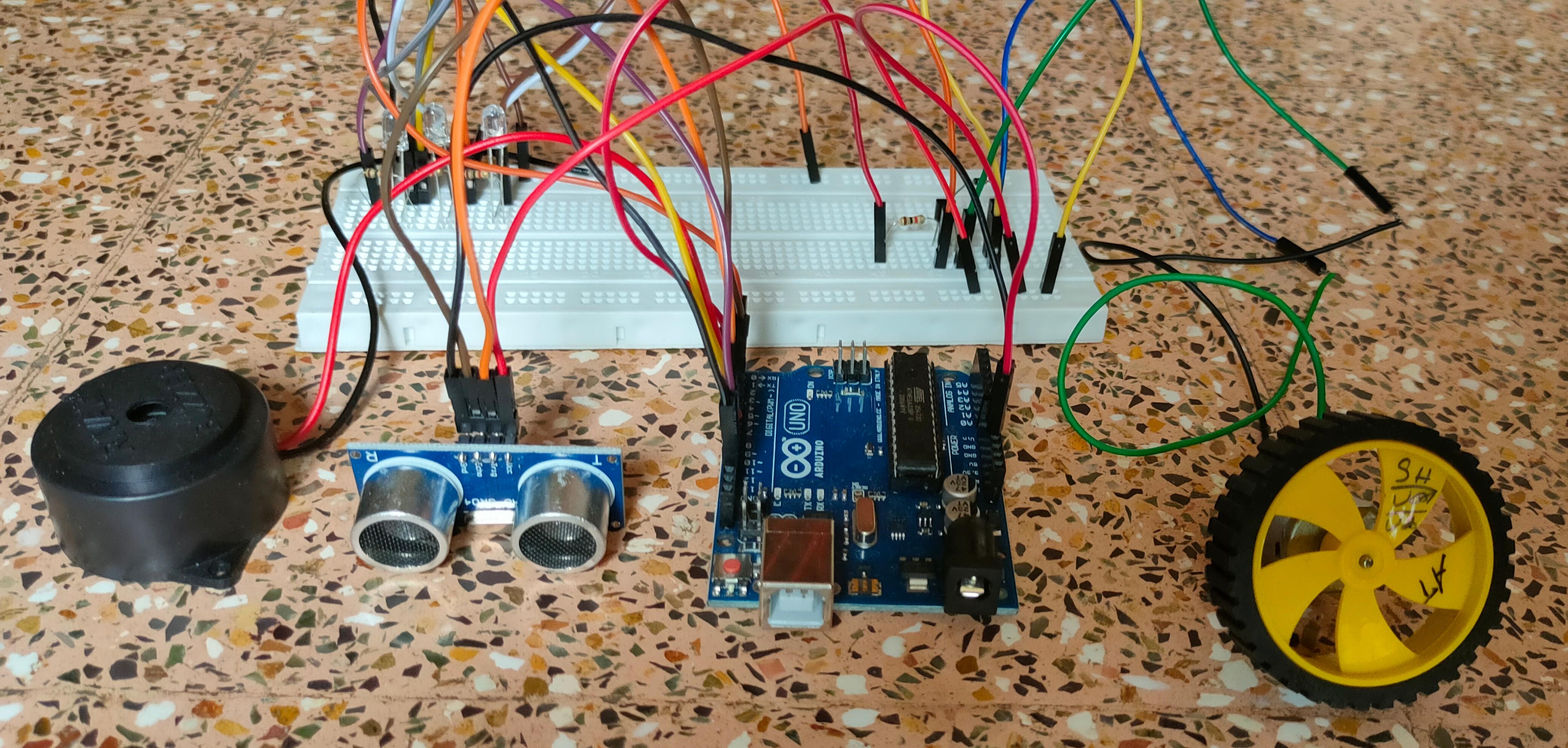
This is a simple Arduino based Collision Avoidance System. It is also known as Forward Collision Warning System. Basically ,it is an advanced driver-assistance system designed to prevent or reduce the severity of a collision. It will continuously monitors the distance between the vehicles/objects in front of it , so that it can provide warning to the driver if the vehicles get too close.
Step 1 : Components Required
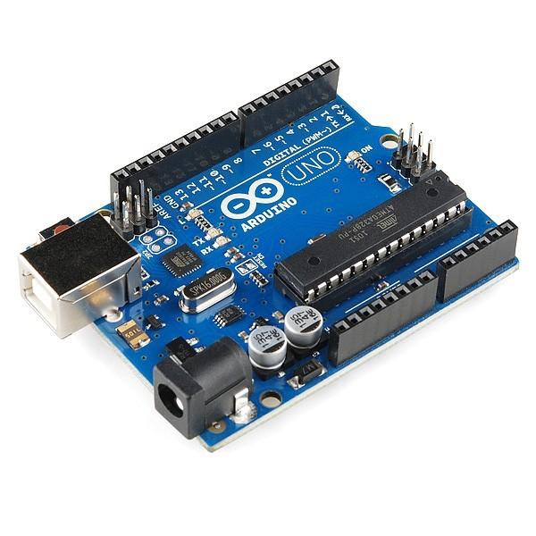
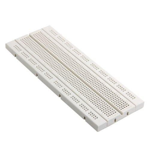
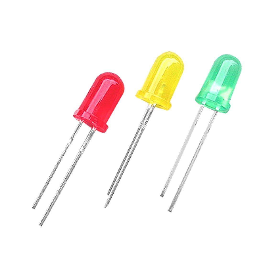
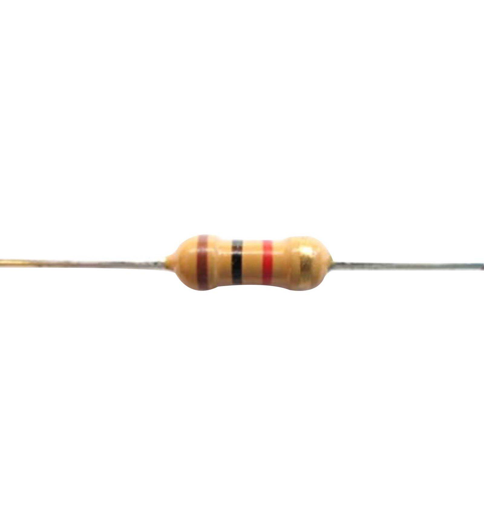
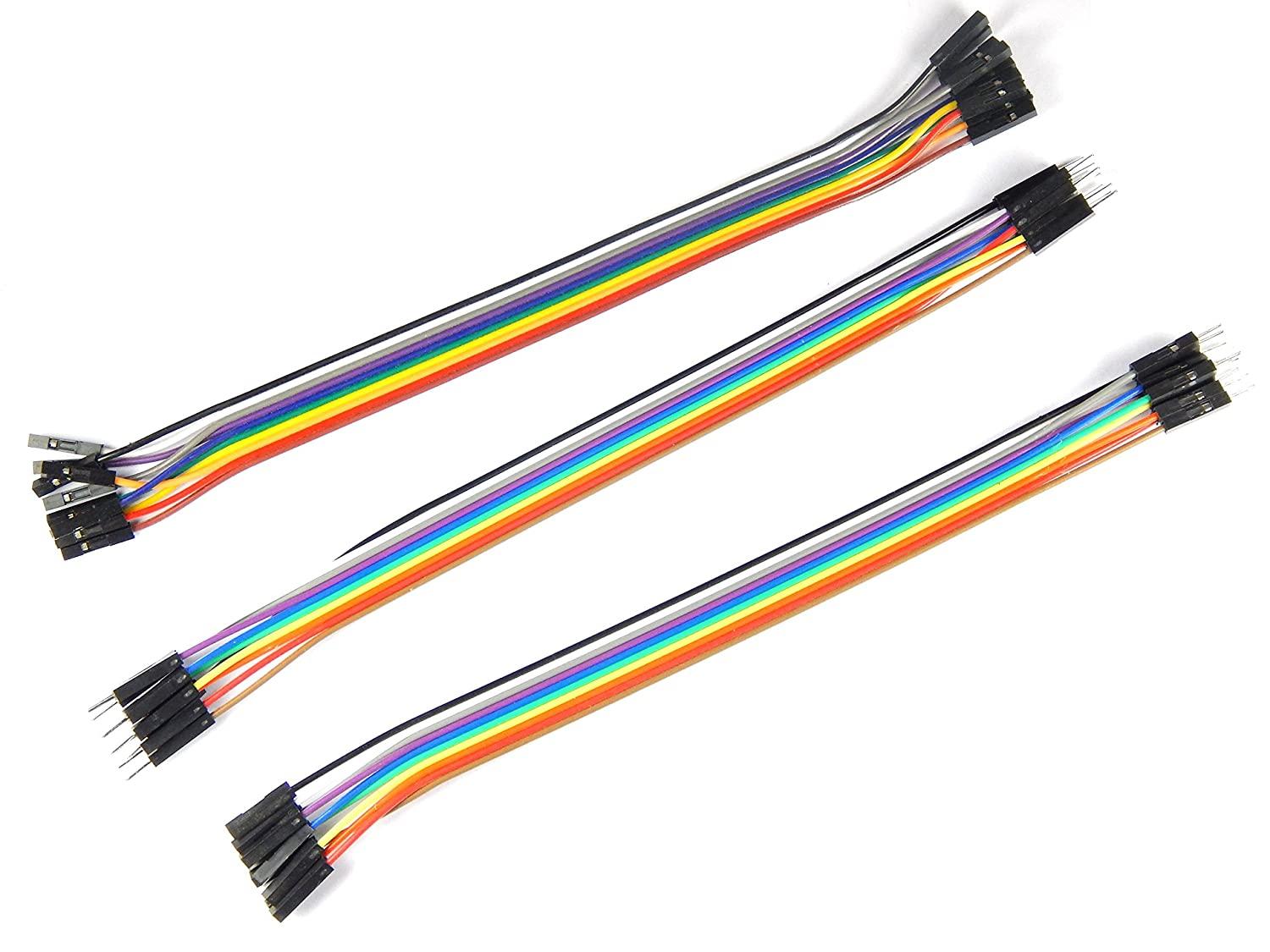
1.Controllers : Arduino UNO
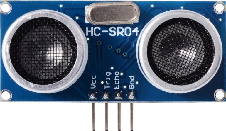
2.Sensor : HCSR04 Ultrasonic sensor
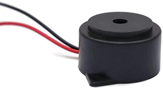
3.Piezo Buzzer : For providing sound
4.Three LEDs(RED,YELLOW,GREEN)
5.Three Resistors(1k)
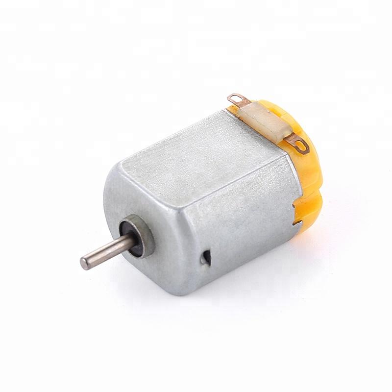
6.DC Motor
7.Few jumper wires for connection
8.Breadboard
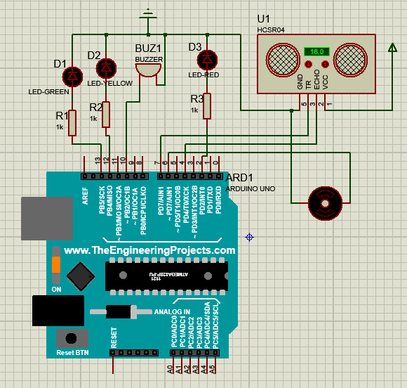
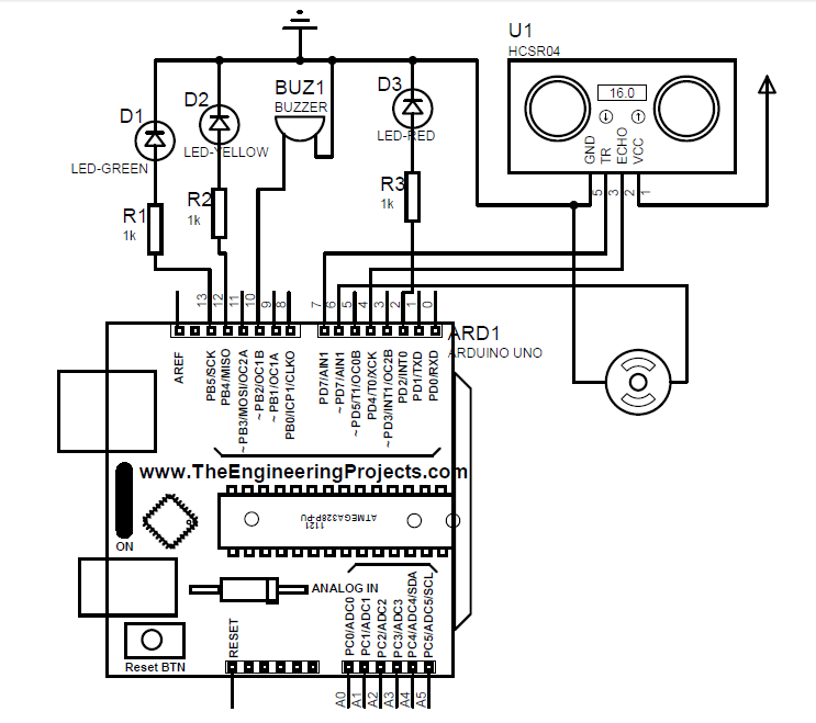
Step 2 : Circuit Design and Connections
.png)
.png)
Now it's time to connect all the components to Arduino through wires!
Ultrasonic sensor(HCSR04) to Arduino Uno
- VCC pin of Ultrasonic sensor is connected to 5V power supply of Arduino.
- GND pin of Ultrasonic sensor is connected to GND pin of Arduino.
- TRIG pin of Ultrasonic sensor is connected to 7th pin of Arduino.
- ECHO pin of Ultrasonic sensor is connected to 4th pin of Arduino.
LED connections : It has two pins Anode(longer leg) and Cathode(shorter leg).
- Green LED : Connect anode to resistor and then to 13th pin of Arduino. Connect cathode to GND of Arduino.
- Yellow LED : Connect anode to resistor and then to 12th pin of Arduino. Connect cathode to GND of Arduino.
- Red LED : Connect anode to resistor and then to 2nd pin of Arduino. Connect cathode to GND of Arduino.
Buzzer
- Positive terminal of buzzer is connected to pin-10 on Arduino.
- Negative terminal is to GND of Arduino.
DC Motor
- It has two terminals.
Connect one terminal to pin-6 on Arduino and another one to GND of Arduino.
Step 3 : Arduino Sketch
const int trigPin = 7;
const int echoPin = 4;
int buzz = 10;
long duration;
int distance;
void setup()
{
pinMode(trigPin, OUTPUT);
pinMode(echoPin, INPUT);
pinMode(13, OUTPUT);
pinMode(12, OUTPUT);
pinMode(2, OUTPUT);
pinMode(6, OUTPUT);
Serial.begin(9600);
}
void loop()
{
digitalWrite(trigPin, LOW);
delayMicroseconds(2);
digitalWrite(trigPin, HIGH);
delayMicroseconds(10);
digitalWrite(trigPin, LOW);
duration = pulseIn(echoPin, HIGH);
distance= duration*0.034/2;
if (distance >= 20)
{
digitalWrite(6, HIGH);
}
else
{
digitalWrite (6, LOW);
}
if (distance >= 100)
{
digitalWrite(13, HIGH);
}
else
{
digitalWrite(13,LOW);
}
if(distance < 100 && distance >= 50)
{
digitalWrite(12, HIGH);
delay(400);
digitalWrite(12, LOW); delay(400);
}
else
{
digitalWrite(12, LOW);
}
if(distance < 50 && distance >= 20)
{
digitalWrite(2, HIGH);
delay(600);
digitalWrite(2, LOW);
delay(600);
digitalWrite(buzz, HIGH);
tone(buzz, 2000);
delay(400);
noTone(buzz);
delay(100);
tone(buzz, 2000);
delay(400);
noTone(buzz);
delay(50);
tone(buzz, 2000);
delay(400);
noTone(buzz);
delay(50);
tone(buzz, 2000);
delay(400);
noTone(buzz);
delay(50); }
else
{
digitalWrite(2, LOW);
}
}
This is the code we used to program our Arduino Uno. You can change the pin connection(Input/Output) if you want. But you have to change the pin number and connection in your code according to the changes that you've made. Otherwise just copy and paste this code in Arduino IDE.
Downloads
Step 4 : Working of the Circuit
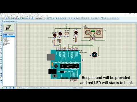
We already discussed about the circuit connection and required code for our project. Make those necessary circuit connection and upload the given code to the Arduino using Arduino IDE. Now let's see about the working of our circuit.
It has four different zones.
Zone 1 : No Warning(Safe zone)
Zone 2 : Visual Warning
Zone 3 : Visual and Audible Warning(Need to pay attention)
Zone 4 : Auxiliary brake
Zone 1 :
When the distance between the object in front of the Ultrasonic sensor is greater than 100cm then no warning will be provided. Only green colour LED will glow and motor will run, indicating that object is at a safe distance.
Zone 2 :
If the distance between the object in front of the sensor is between 100-50cm ,then yellow colour LED will start blinking. This indicates that "Object is approaching". Motor will continue to run.
Zone 3 :
If the distance get reduced between 50-20cm ,then red colour LED will start blinking. In addition to that a beep sound is also provided by the buzzer. Driver needs to respond in this situation. In spite of the warning, the motor will continue to run.
Zone 4 :
This is the last zone. Here, if the distance between the object is even get reduced to less than 20cm ,then the motor will automatically stop functioning.
Step 5 : Test the Setup
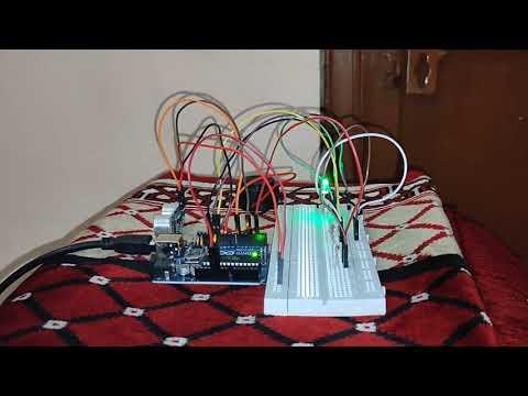
This is the hardware working of this project. I haven't added the motor . If you want you can add the motors also. I have already provided the connections and code for motor in step 2 & 3.
Thanks for reading my instructable.
I hope you enjoyed this and learnt something new.