Coin Collector and Register for Vending Machines
by fcodiegomoreira in Circuits > Arduino
617 Views, 3 Favorites, 0 Comments
Coin Collector and Register for Vending Machines

In today's context, the automation of processes and the integration of electronic technologies into practical solutions have become increasingly essential. An innovative example of this trend is the development of a coin collection and registration system for a donation box. This project aims to simplify and optimize the donation process, providing a more efficient and transparent experience for both donors and those responsible for collecting the donations.
The system developed in this article consists of a coin acceptor, responsible for receiving and capturing the coins inserted by the user. According to pre-programmed settings, it selects only the coins allowed by the system, thus ensuring accuracy in counting.
After counting the coins, the system records the total amount of money collected and displays this information on an LCD screen, allowing a clear and immediate view of the total amount obtained through donations.
In addition to its initial application as a donation box, this system can be evolved into a product sales system. With a few modifications, it can be configured to dispense products upon payment, acting as a vending machine. This additional functionality significantly expands the system's potential uses, making it a multifunctional solution for various sectors and purposes.

Now... Let get started!
Development Money Donation Box Project
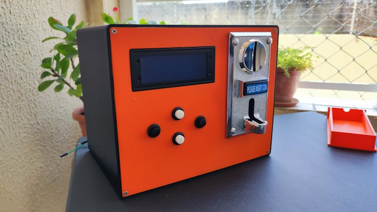
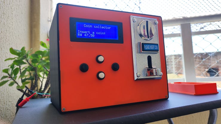
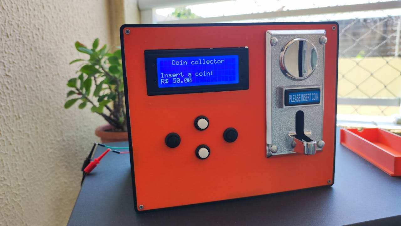
The structure of the donation system is shown in the figure below. It consists of 4 buttons, a 20x4 LCD display, a coin acceptor, and an Arduino-based board.
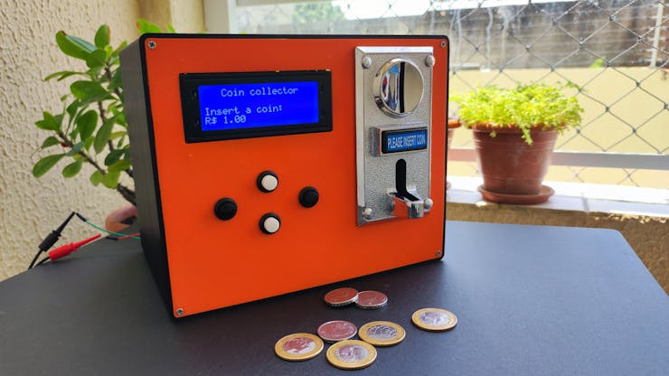
Below, we have the device presented with the coins.
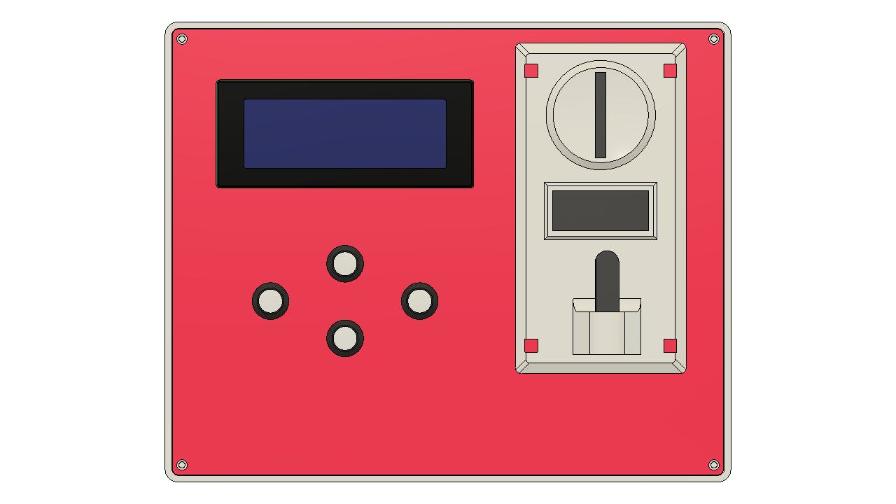
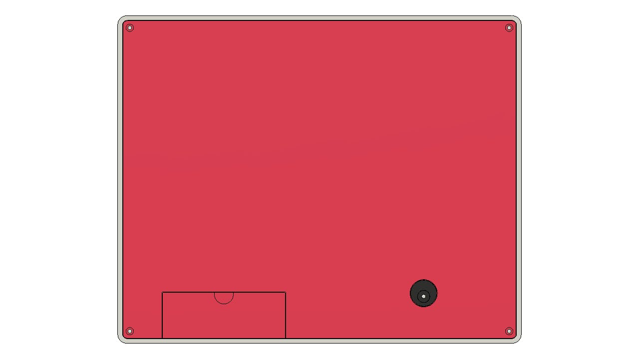
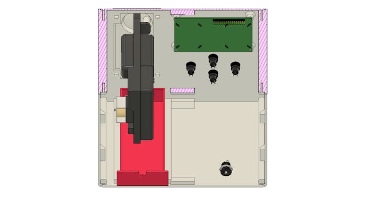
Below we have the structure that was modeled in Autodesk Fusion software.
Below we have an image of the internal structure of the device.
Next, we will present the project's operating structure based on electronic elements and the 6 steps of working.
Step 1 - Inserting Coins
When a coin is inserted into the coin purse, it identifies and counts it. The value of the coin is sent to the Arduino based board through pulses sended of coin, which updates the total collected.
Step 2 - Counting and Registration
The Arduino board processes the data from the coin purse, counting the money and keeping an accurate record of the total collected. This data is updated in real time and displayed on the LCD display.
Step 3 - Interaction with the LCD Display
The 20x4 LCD display displays information such as total money collected, status messages, and instructions for the user. The display updates automatically as the value of coins increases or as the user interacts with the system.
Step 4 - Using the Buttons
The system is composed for 4 buttons.
Button 1 (Start/Stop Counting): Allows you to start or stop counting coins. When pressed, the button activates or deactivates the automatic counting of the coin purse.
Button 2 (Reset Total): Allows you to reset the total collected to zero. Ideal for preparing the system for a new collection session.
Button 3 (Show Status): Toggles between different display modes on the LCD display, such as showing the total collected, the number of coins inserted or other useful information.
Button 4 (Settings/System Configuration): Accesses a settings menu on the LCD display, where the user can adjust system parameters, such as the value of each currency or configure personalized messages.
Based on each step above, we create 3D modeling and electronic project programming. Now, let's understand the electronic structure of the project.
Electronic Structure of the Project
Below we have the internal structure of the coin collector. As you can see, the system consists of an electronic coin acceptor, a 20x4 LCD display and a shield board for connecting all the cables to the Arduino UNO.
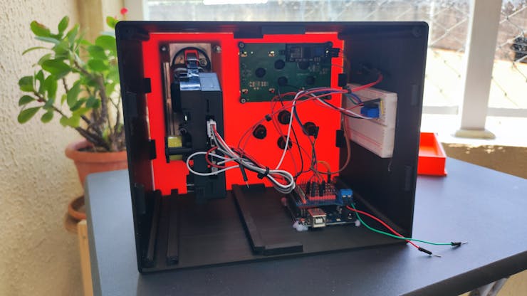
The system developed is supplied with a power supply of 12V for a coin acceptor and the electronic circuit of the Arduino board.
In this project it was developed a printed circuit board to connect all wires and easier to assembly all electronic circuit of all electronic devices.

This electronic board was developed to be a shield and connects directly to the Arduino UNO board. From there, you have access to all Arduino pins and various power rails from GND, +3V3, +5V and Vin.
Using the electronic connections, we developed the code below. Its purpose is to read the coin acceptor pulses and display the value of the money count placed in the machine.
#include  <Arduino.h>
#include <Wire.h> //Biblioteca de Comunicacao I2C
#include <LiquidCrystal_I2C.h> //Biblioteca I2C do LCD 16x2

LiquidCrystal_I2C lcd(0x27,20,4);  // Configurando o endereco do LCD 16x2 para 0x27

// variable use to measuer the intervals between impulses
int  time = 0;
// Number of impulses detected
int impulsCount=0;
// Sum of all the  coins inseted
float total_amount=0;

void setup() {
 pinMode(2, INPUT_PULLUP);
  Serial.begin(9600);
 // Interrupt connected  to PIN D2 executing IncomingImpuls function when signal goes from HIGH to LOW
  attachInterrupt(0,incomingImpuls, FALLING);
    lcd.init();                      //Inicializacao do LCD
  lcd.backlight();
    lcd.clear();

  lcd.setCursor(3,0);
  lcd.print("Coin collector");
  lcd.setCursor(0,2);
  lcd.print("Insert a coin:");
  lcd.setCursor(0,3);
  lcd.print("R$ ");
  lcd.setCursor(3,3);
  lcd.print(total_amount);
   delay(2000);
}

void incomingImpuls()
{
  impulsCount=impulsCount+1;
  time=0;
}

void loop() {
  time=time+1;

  if (time>=30  and impulsCount==5){
    total_amount=total_amount+0.5;
    lcd.setCursor(0,3);
    lcd.print("                ");
    lcd.setCursor(0,3);
    lcd.print("R$ ");
    lcd.setCursor(3,3);
    lcd.print(total_amount);
  Serial.print(" Total:");
  Serial.println(total_amount);
    impulsCount=0;
  }

   if (time>=30 and impulsCount==4){
    total_amount=total_amount+1;
    lcd.setCursor(0,3);
    lcd.print("                ");
    lcd.setCursor(0,3);
    lcd.print("R$ ");
    lcd.setCursor(3,3);
    lcd.print(total_amount);
  Serial.print(" Total:");
  Serial.println(total_amount);
    impulsCount=0;
  }

  if(time>15 && (impulsCount<4||impulsCount>5))
  {
    impulsCount=0;
  }

  delay(15);
}
To ensure that each pulse is correctly identified and counted, we use the Arduino's external interrupt. The code below shows the configuration of the external interrupt 0 on pin D2 of the Arduino.
 pinMode(2, INPUT_PULLUP);
 Serial.begin(9600);

 attachInterrupt(0,incomingImpuls, FALLING);
 lcd.init();                      //Inicializacao do LCD
 lcd.backlight();
 lcd.clear();
Below we have the external interrupt function. It is responsible for counting the number of pulses received from the coin acceptor.
void incomingImpuls()
{
  impulsCount=impulsCount+1;
  time=0;
}
After counting the pulses, the system, through the time variable, counts 30 code execution cycles to ensure that the impulsCount variable has counted all the pulses sent by the coin acceptor.
After this, the conditions will be tested to verify which coin was inserted.
  time=time+1;

  if (time>=30  and impulsCount==5){
    total_amount=total_amount+0.5;
    lcd.setCursor(0,3);
    lcd.print("                ");
    lcd.setCursor(0,3);
    lcd.print("R$ ");
    lcd.setCursor(3,3);
    lcd.print(total_amount);
  Serial.print(" Total:");
  Serial.println(total_amount);
    impulsCount=0;
  }
In the above condition, it is checked whether the value of the time variable is greater than or equal to 30 and whether the number of pulses received is equal to 5. If this is true, it means that the user inserted a 50 cent coin.
In this condition, 0.5 will be added to the total_amount variable and the value will be displayed in the system. See the image below.
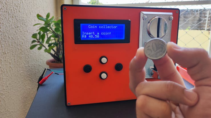


The next condition is used to detect that the user has inserted a 1 real coin. When a 1 real Brazilian coin is inserted, the system receives 4 pulses from the coin acceptor.
   if (time>=30 and impulsCount==4){
    total_amount=total_amount+1;
    lcd.setCursor(0,3);
    lcd.print("                ");
    lcd.setCursor(0,3);
    lcd.print("R$ ");
    lcd.setCursor(3,3);
    lcd.print(total_amount);
  Serial.print(" Total:");
  Serial.println(total_amount);
    impulsCount=0;
  }
When it enters this condition, the total_amount variable is incremented with the value 1.
total_amount=total_amount+1;
Below we have the 1 real coin being inserted into the system and the value being changed on the 20x4 LCD display.

As you can see, the system correctly detects and calculates the value entered for each currency. From there we can expand to other applications and use it to create a product release system when the user inserts a certain amount of money.
Upcoming Updates for This Project
The next step for this project is to develop an electronic board with ESP32 and remove the Arduino. The goal of using ESP32 is to allow the device to have access to the internet and we can receive this data on a web server to obtain payment information and store this information in a database.
From this, we can expand the processing capabilities of the system and integrate it with other technologies
Conclusion
This coin donation box project, which can be evolved into a sales system, demonstrates the power of to be used in several applications of payment system. Thanks to the precision of 3D printing and the reliability of printed circuit boards, it was possible to create an innovative and efficient solution.
For those seeking quality and precision in their projects, we recommend the services of JLCPCB and JLC3DP. With years of experience and cutting-edge technology, these companies offer complete solutions for PCB manufacturing and 3D printing, ensuring that your ideas become reality with excellence and efficiency. Printed circuit boards can be manufactured starting at $2, and the price of 3D printing starts at $0.3, making these services accessible for all types of projects.
