Class Countdown Clock With Raspberry Pi Pico W and MQTT
by danapolsky in Circuits > Clocks
1836 Views, 7 Favorites, 0 Comments
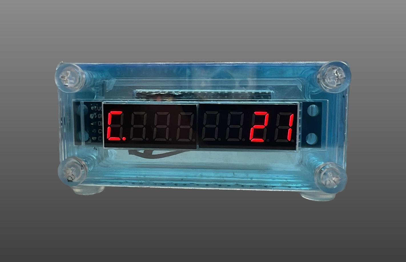
Class Countdown Clock With Raspberry Pi Pico W and MQTT
.jpg)
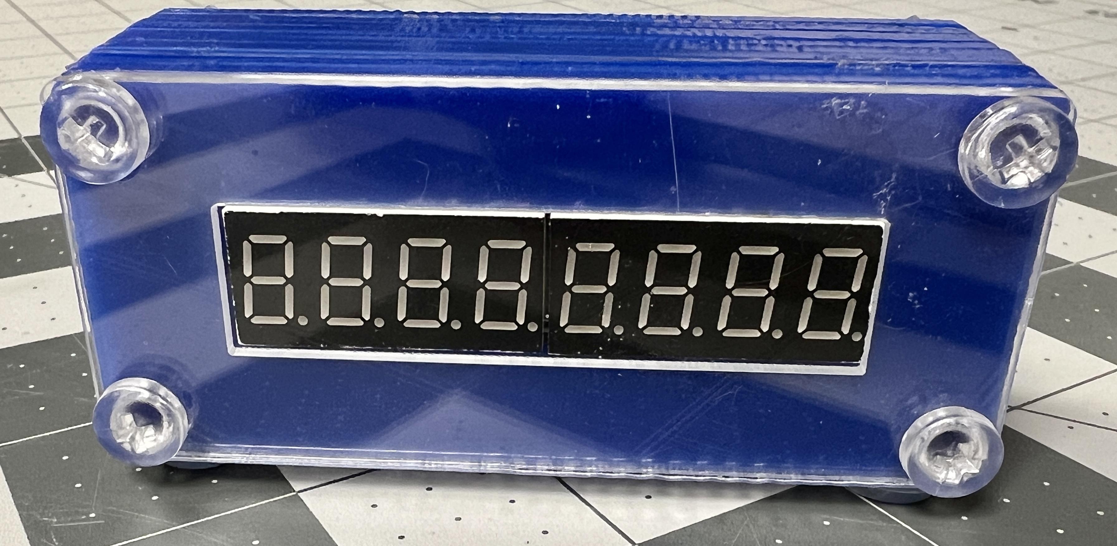
A countertop device that counts down to the end of the current class period while a class is active, and then count down to the start of the next class between periods. Clocks are managed through an MQTT server running on a Linux device.
These clocks automatically follow the correct schedule and events based on an iCalendar schedule, so they still work for special schedules. The ultimate goal of the project was to help teachers manage their class time more efficiently.
Downloads
Supplies
Materials Per Clock (Please see the attached pdf for much more in-depth details on the materials):
- 1x Raspberry Pi Pico W
- 1x 5V 2.5A Power Supply with MicroUSB cable
- 1x 8 digit Max7219 7-segment display
- 5x Female to Female Jumper Wires (75 mm)
- 4x 40 mm M5-0.8 Clear Nut and Bolt Set
- 4x Rubber Feet Pads
- 2x 10 Pin 2.54 Pitch Male Headers
- If laser cutting:
- 0.0625" clear cast acrylic
- 0.125" opaque cast acrylic
1 Server:
- Raspberry Pi 4, old laptop, or anything that can connect to the internet and run a distribution of Linux
- Accessories needed to power/access the server
Supplies:
- Lead-Free Solder
- Example: 0.8mm Lead Free with Rosin Core
Tools:
- MicroUSB to USB cable to set up the Pico W's software
- Phillips-Head Screwdriver
- Soldering Equipment
- Soldering Iron (Get a decent one)
- Solder Sucker (For inevitable mistakes)
- Solder Fume Extractor (recommended)
- Breadboard
- Big enough to fit a Raspberry Pi Pico W to help with soldering it
- Example: Half-Size Breadboard with Mounting Holes
- A small amount of masking tape, around 4" (10.16 mm)
- Pliers (for splitting male headers)
- Laser Cutter or 3D Printer
Downloads
Soldering the Raspberry Pi Pico W
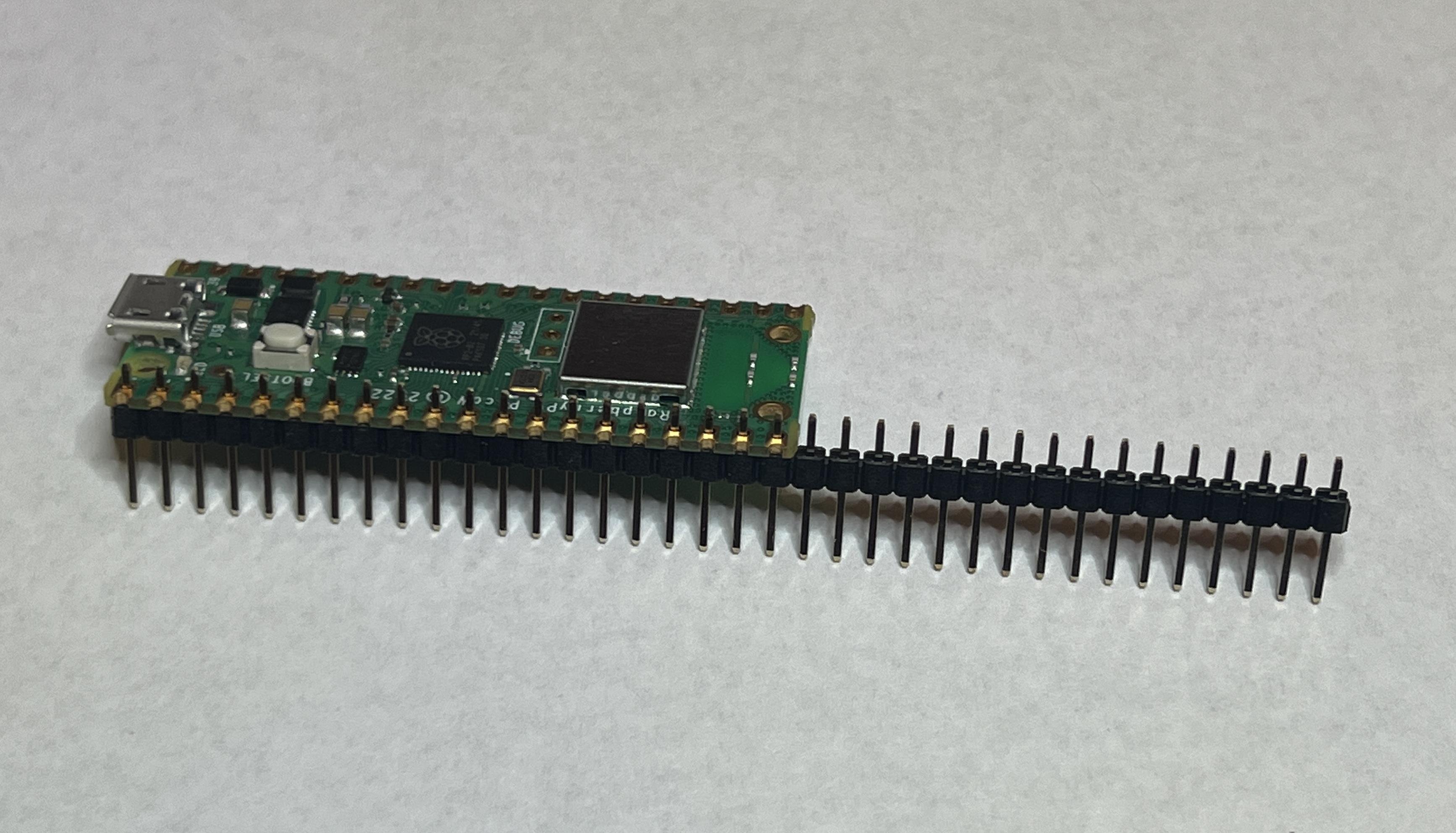
- Insert a row of male headers into one side of the board so that all the slots are filled and the longer side of the headers is facing away from the board, as shown in the 1st picture
- Use a pair of pliers to carefully snap the excess headers off
- Repeat steps 1-2 for the other side so that both sides have all of their header slots filled
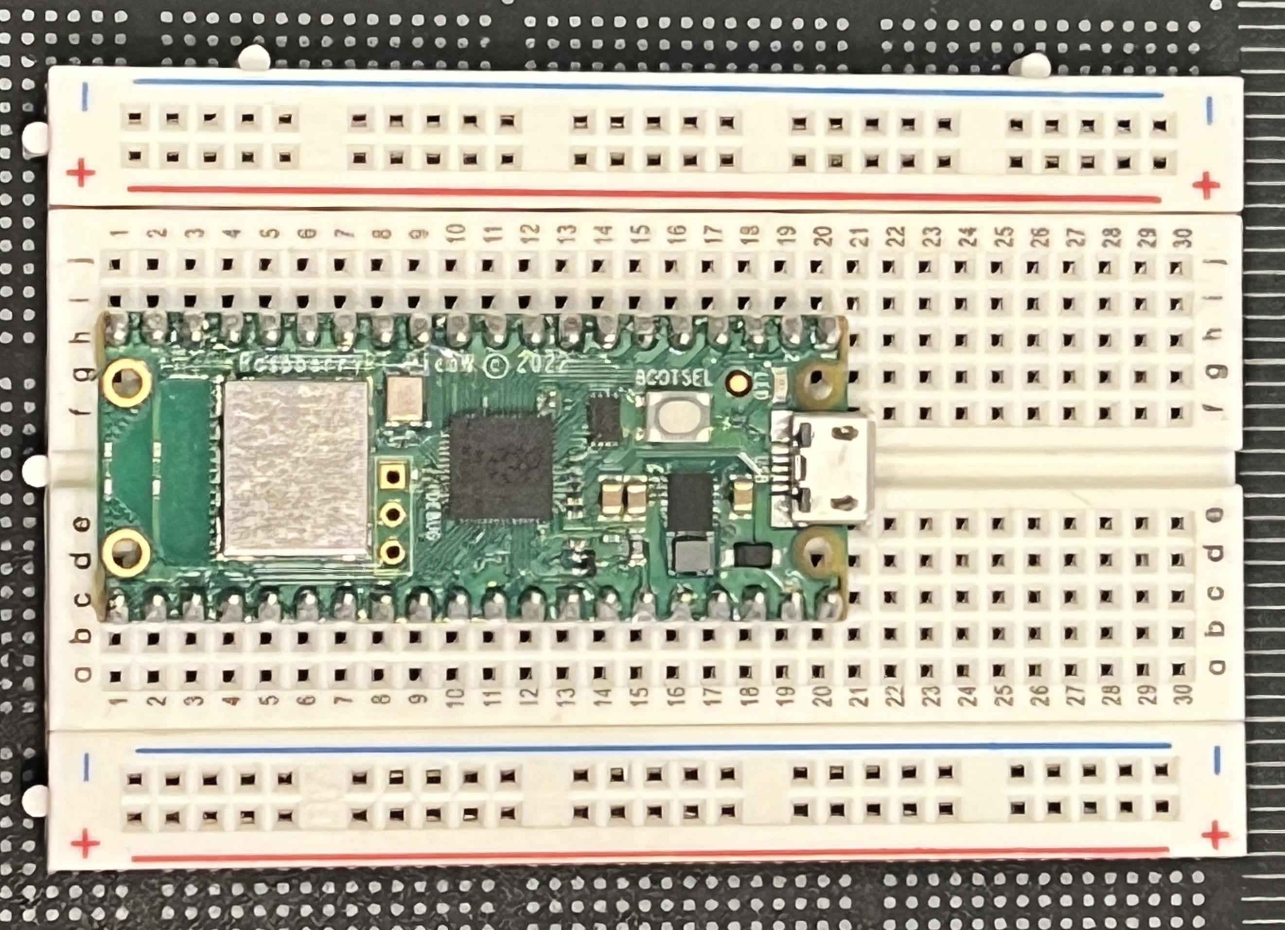
- Place the board with the headers onto a breadboard, as shown in the 2nd picture
- Solder each connection, making sure no solder bridges, where solder bridges between two connection points, are formed
- Carefully remove the board from the breadboard by lifting up opposite sides little by little
Soldering the 8 Digit Max7219 7-Segment Display
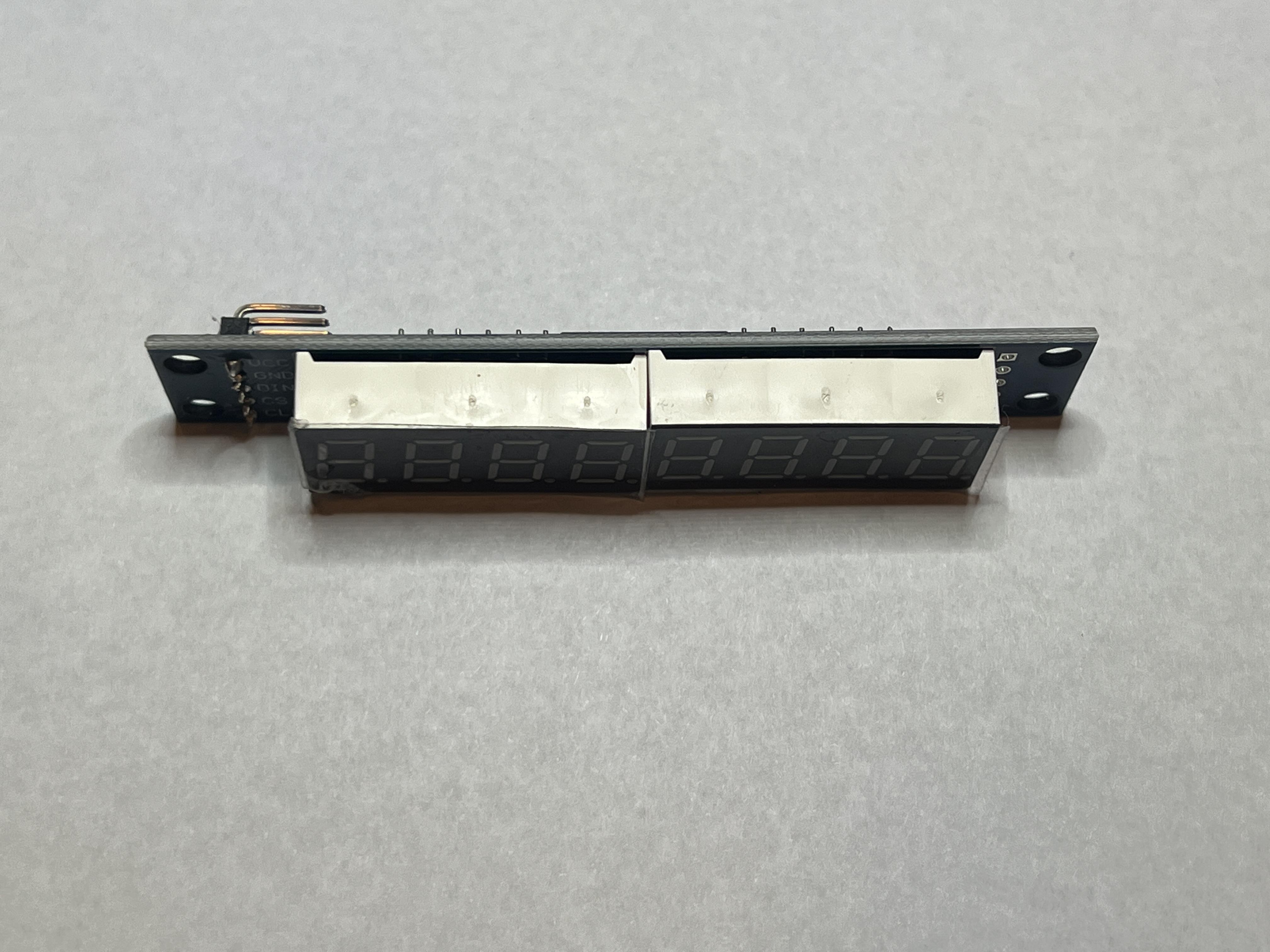

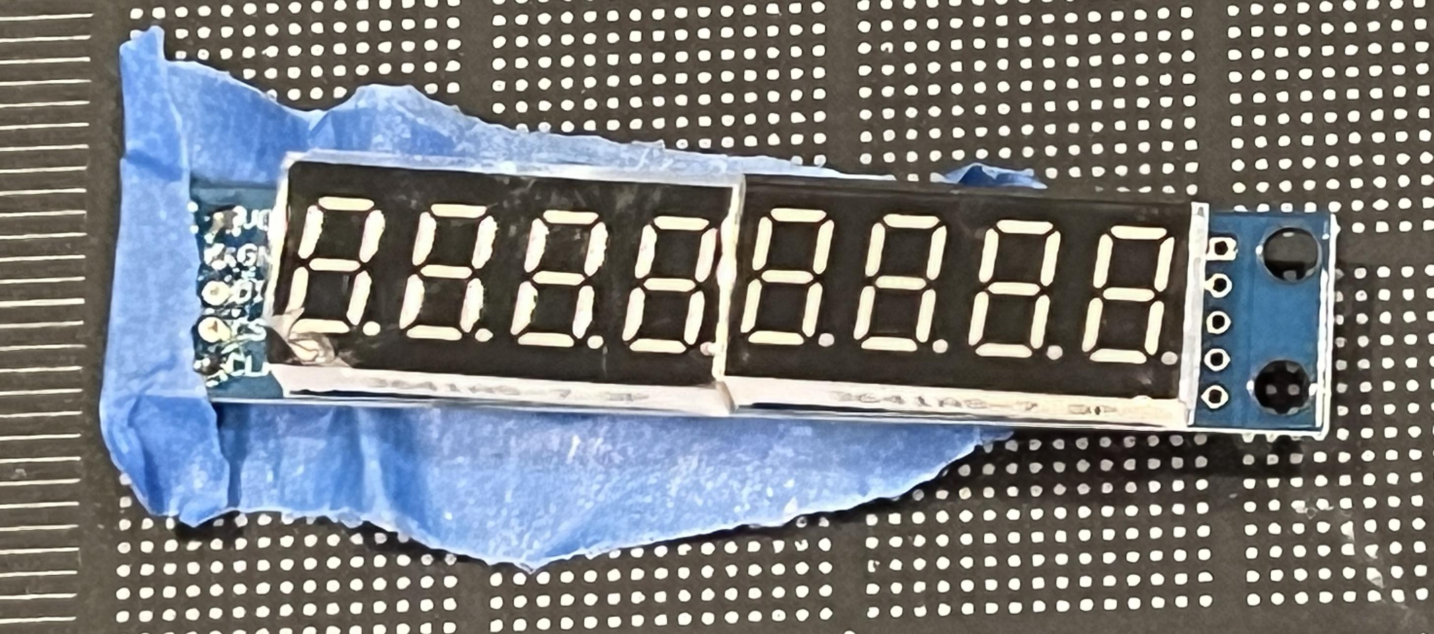
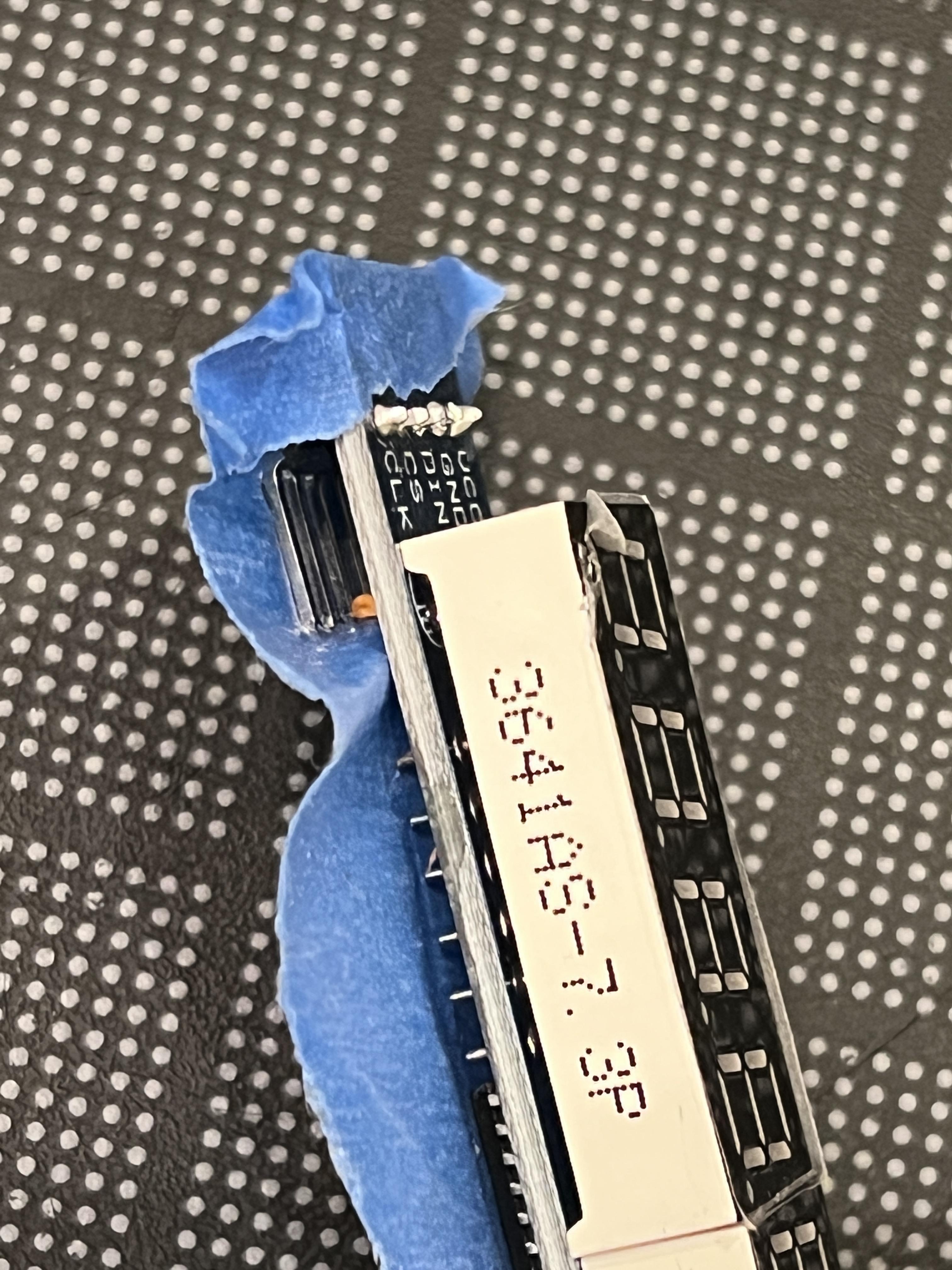
- Take the 90 degrees 5 pin headers that come with the display and insert it into the display PCB on the side labeled "VCC GND DIN CS CLK," as shown in the 1st and 2nd pictures
- Using masking tape, temporarily secure the headers in place without blocking access to the soldering points, as shown in the 3rd and 4th pictures
- Solder each connection, making sure no solder bridges are formed
- Remove the masking tape from the display and check that the headers are still at a right angle
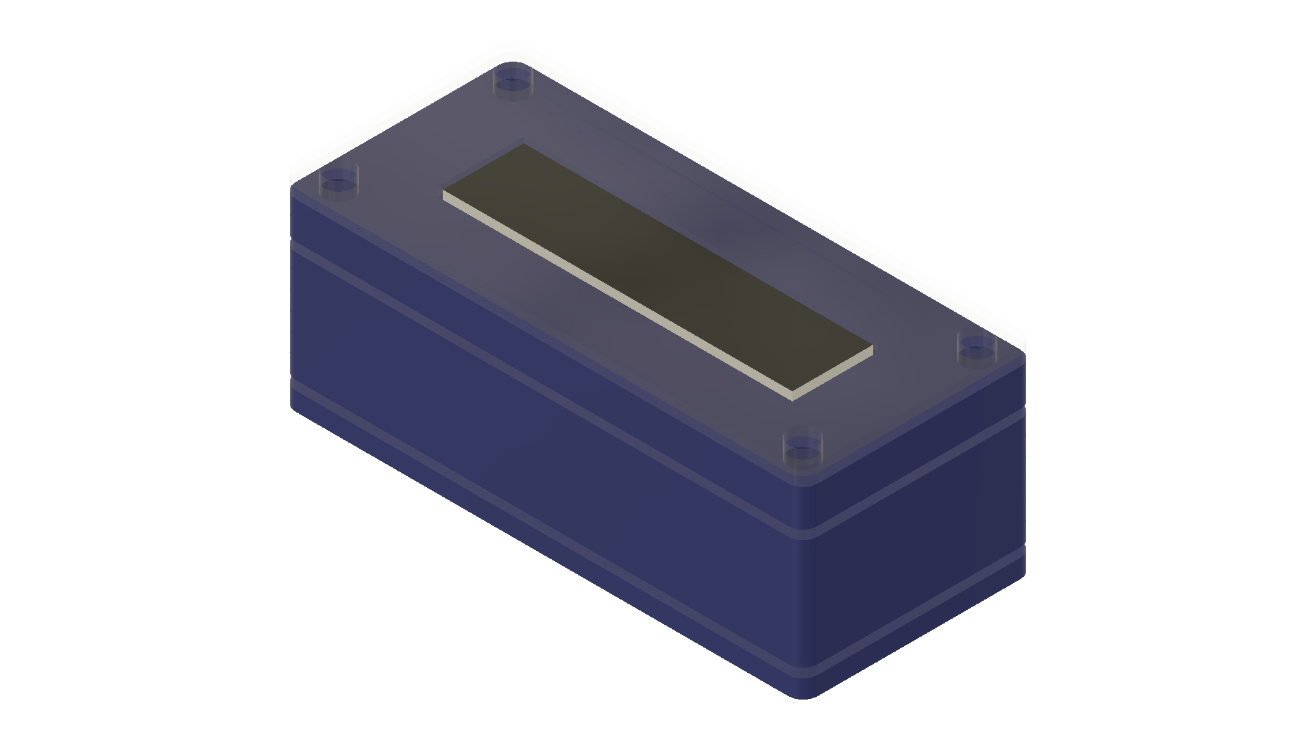
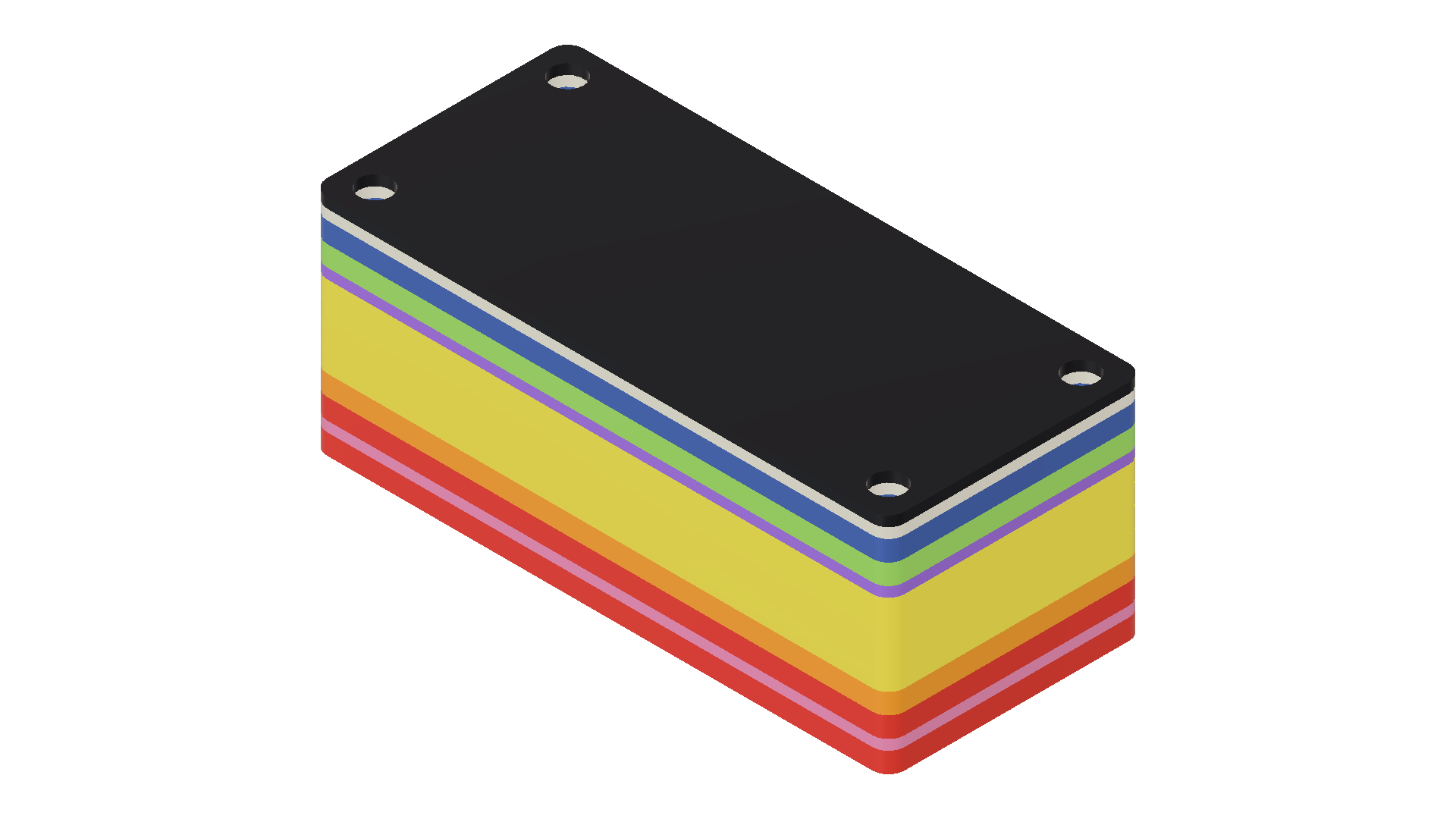
Laser Cutting or 3D Printing the Case

Both the laser cutting and 3D printing files can be found here: https://www.printables.com/model/410589-class-countdown-clock-case
The following should be kept in mind when laser cutting or 3D printing:
- Layers A and F are no longer necessary and as such are not included.
- Layer K should be made with a transparent material. Alternatively, leave it out.
- 4 separate Layer Es (laser cut or 3D printed) or a single 3D printed One Piece E should be used.
The information in the details section of the Printables Page can also be found below. Some of the information, namely where to buy the acrylic, has been removed since it was already included in the supplies section.
Laser Cutting Information
Make sure to laser cut in a well-ventilated area. Acrylic emits fumes that smell but are not lethally toxic. Regardless, it is best practice to take steps to avoid inhaling the fumes if possible.
Monitor the laser cutter during the entire duration of the cut. Fumes will get trapped between the acrylic and the bed while cutting. Let the acrylic sit in the ventilated area after the cut completes for a few minutes to allow these fumes to dissipate.
Naming Conventions
Folders:
LASER {Unit of Measure} {File Type} {Acrylic Type} {Thickness in Inches} Layers
Files:
{Thickness in Inches}_Layers_{Layout}_{Unit of Measure}
- The compact layout has the layers arranged in a 250 mm x 210 mm (9.84 in x 8.27 in) rectangle, the same size as a Prusa MK3 bed
- The normal layout has the layers arranged in a 48 in x 24 in (1219.2 mm x 609.6 mm) rectangle, one of the acrylic sheet dimensions sold by Falken Design, a manufacturer of cast acrylic in the United StatesThe compact layout has the layers arranged in a 250 mm x 210 mm (9.84" x 8.27") rectangle, the same size as a Prusa MK3 bed
- The normal layout has the layers arranged in a 48" x 24" (1219.2 mm x 609.6 mm) rectangle, one of the acrylic sheet dimensions sold by Falken Design, a manufacturer of cast acrylic in the United States
Nesting / Cutting Multiple Cases at Once
- VCarve Pro files are included in Zipped Folders and follow the naming conventions of the other laser-cutting files
- Use the nesting tool to arrange the layers on the sheet, then re-export in your preferred file format
Setting Up the Server
Follow the instructions in the "README.MD" in the following link to set up the server for the clocks: https://gitlab.com/danapolsky/class-countdown-clock-server
Make sure to keep track of the following:
- WiFi
- ssid and password
- MQTT
- Username and password
- Valid topics
- Server
- Static IP Address
Replace the iCalendar placeholders in Schedules.json with a valid calendar where events could be parsed based on inputted values in Names.json. The iCalendar from the school service Blackbaud is known to work with the parsing algorithms.
Replace the values found in the clock code in the Setting Up The Raspberry Pi Pico W section with the new values you assigned to have the clocks communicate with the server.
Setting Up the Raspberry Pi Pico W
Setting up MicroPython
- Download the latest build for the Pico W on your computer: https://micropython.org/download/rp2-pico-w/
- Push and hold the BOOTSEL button on the Pico W
- While holding down the button, plug it into your computer
- Drag and drop the .uf2 from your computer's hard drive to the drive labeled "RPI-RP2"
For more information, see: https://www.raspberrypi.com/documentation/microcontrollers/micropython.html
Download and Install Thonny
Download the Code
- Download the pico folder found in this git repository: https://gitlab.com/danapolsky/class-countdown-clock
- Unzip the contents of the folder
- Replace the placeholder values in the code with the values collected in Setting Up The Server
- login.json folders should match between the server and the clock
- schedule.txt should include a valid schedule's topic name, found in schedules.json
Upload the Code to the Pico W
- Open Thonny
- Display files by checking "Files" in View > Files
- In the bottom right where it says a Python version, click on it and select the one that appears as either "MicroPython RP2040" or "MicroPython Raspberry Pi Pico"
- In the files dialogue on the left, navigate to where you downloaded the code to your computer
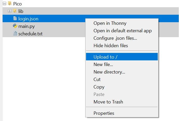
- Select all the files and folders in the Pico directory, right click on them, and press "Upload to /," as shown in the 1st picture
- The code should now run on startup
Clock Assembly
I created instructions for the clock assembly based on the Fusion 360 model in Cadasio.
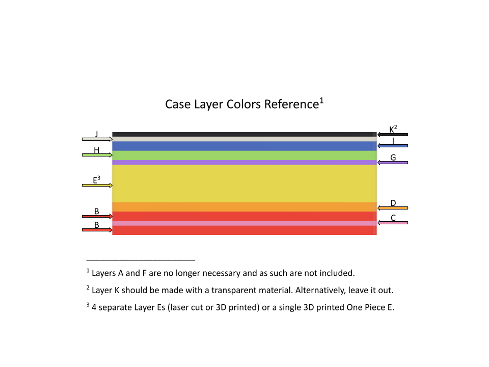
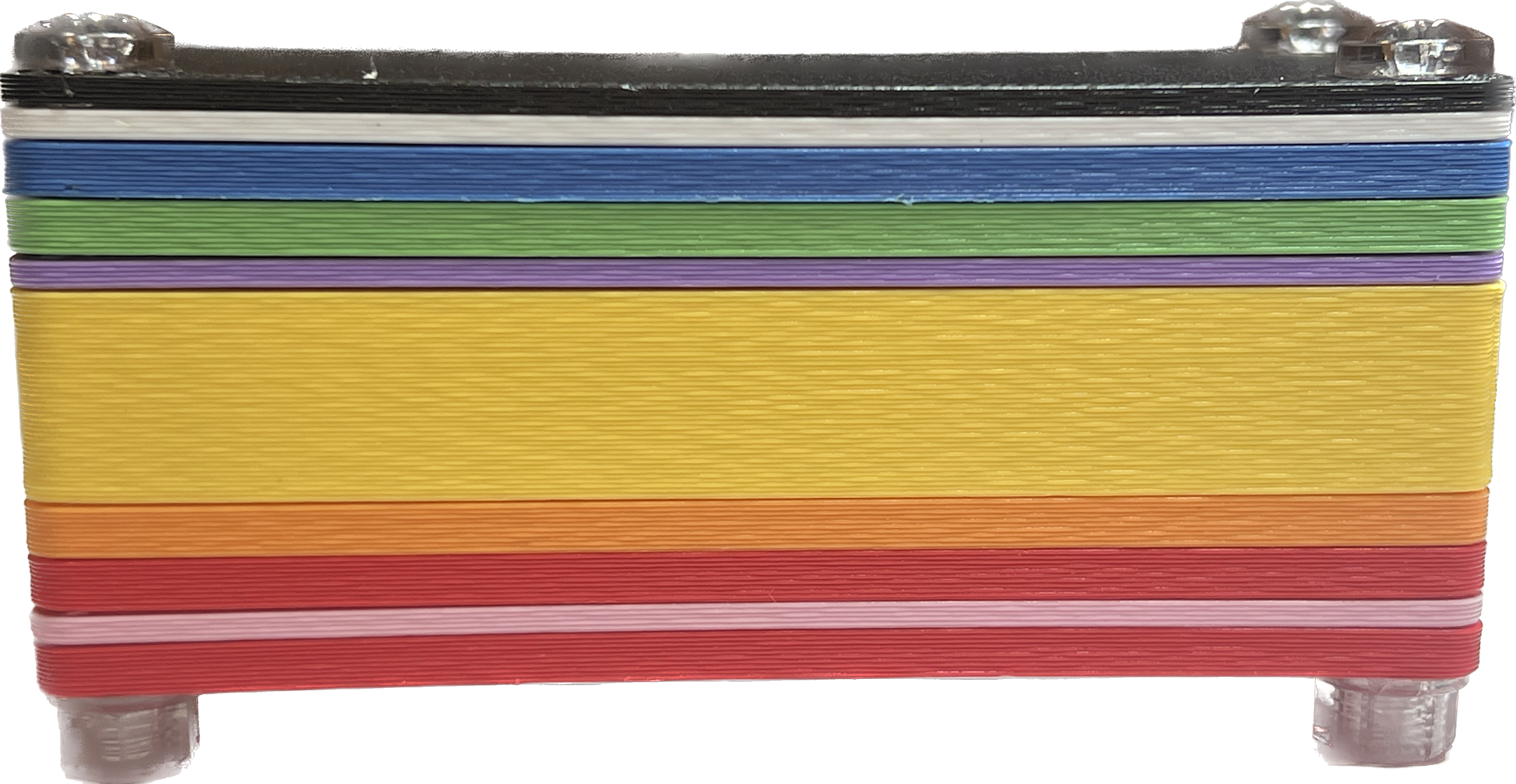
The layers have been color-coded to assist with assembly (also shown in picture):
- B: Red
- C: Pink
- D: Orange
- E: Yellow
- G: Purple
- H: Green
- I: Blue
- J: White
- K: Black
You can access these instructions with their animations online: https://instructions.online/?id=4231-class%20countdown%20clock.
Attached below are these same instructions as a pdf.
Downloads
Done!
I hope you enjoyed building a device to help you keep track of your schedule!