Circuit Python Interactive Infinity Mirror
by alsleben in Circuits > LEDs
5063 Views, 70 Favorites, 0 Comments
Circuit Python Interactive Infinity Mirror
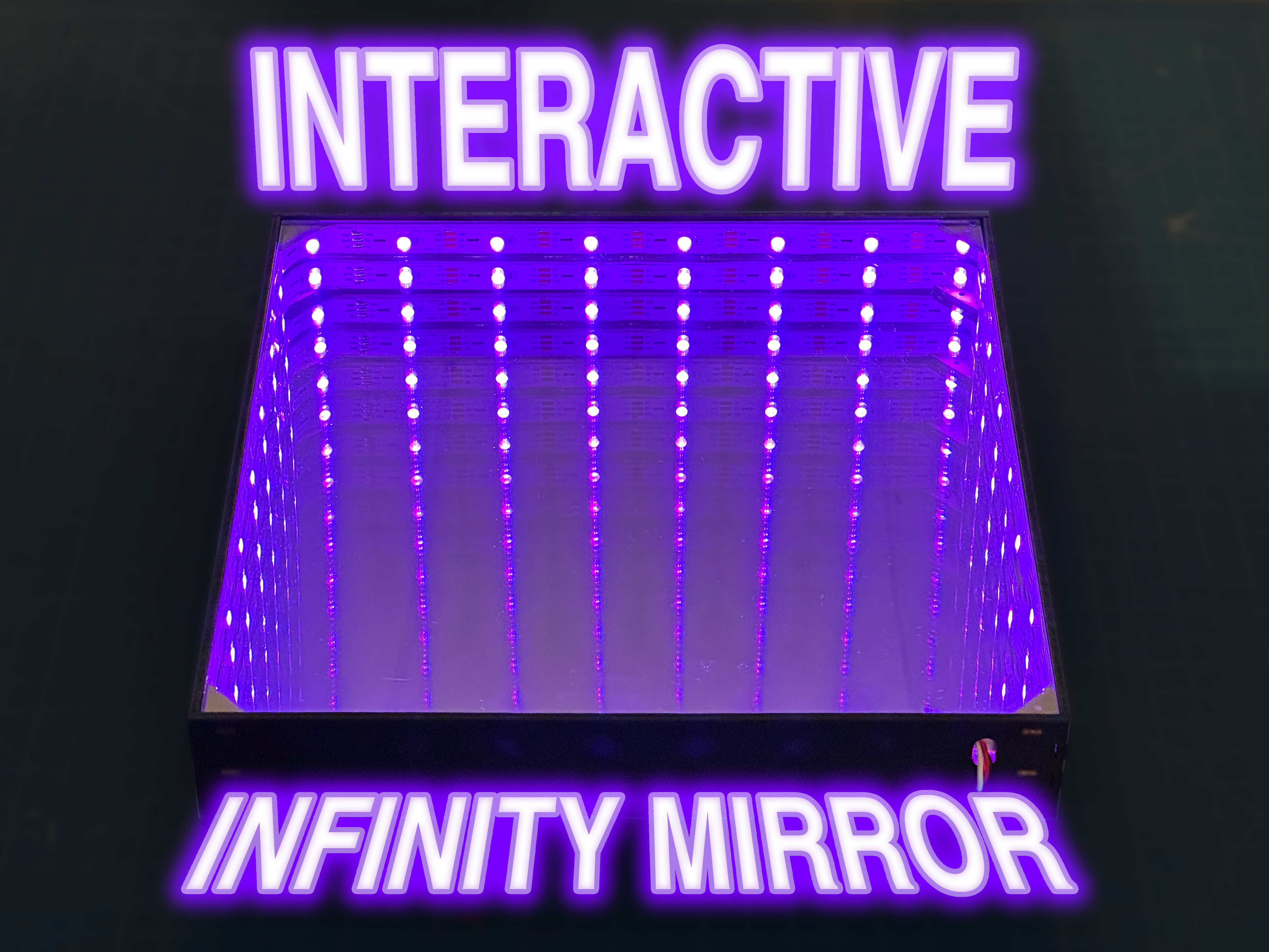
Hi! Welcome to my Instructable! I'm Leonard and this project is part of the "Make Art" assigment from a class at Boston College called "Physical Computing". In this project, you will be making an interactive "infinity mirror" powered by a CircuitPlayground Bluefruit Board by Adafruit and coded using Circuit Python. This Project makes use of a Laser Cutter, but if you don't have access to one, there's many ways to get materials cut for you! I trust makerstock.com for laser cutting, but there are many companies out there that can ship custom laser-cuts!
Supplies
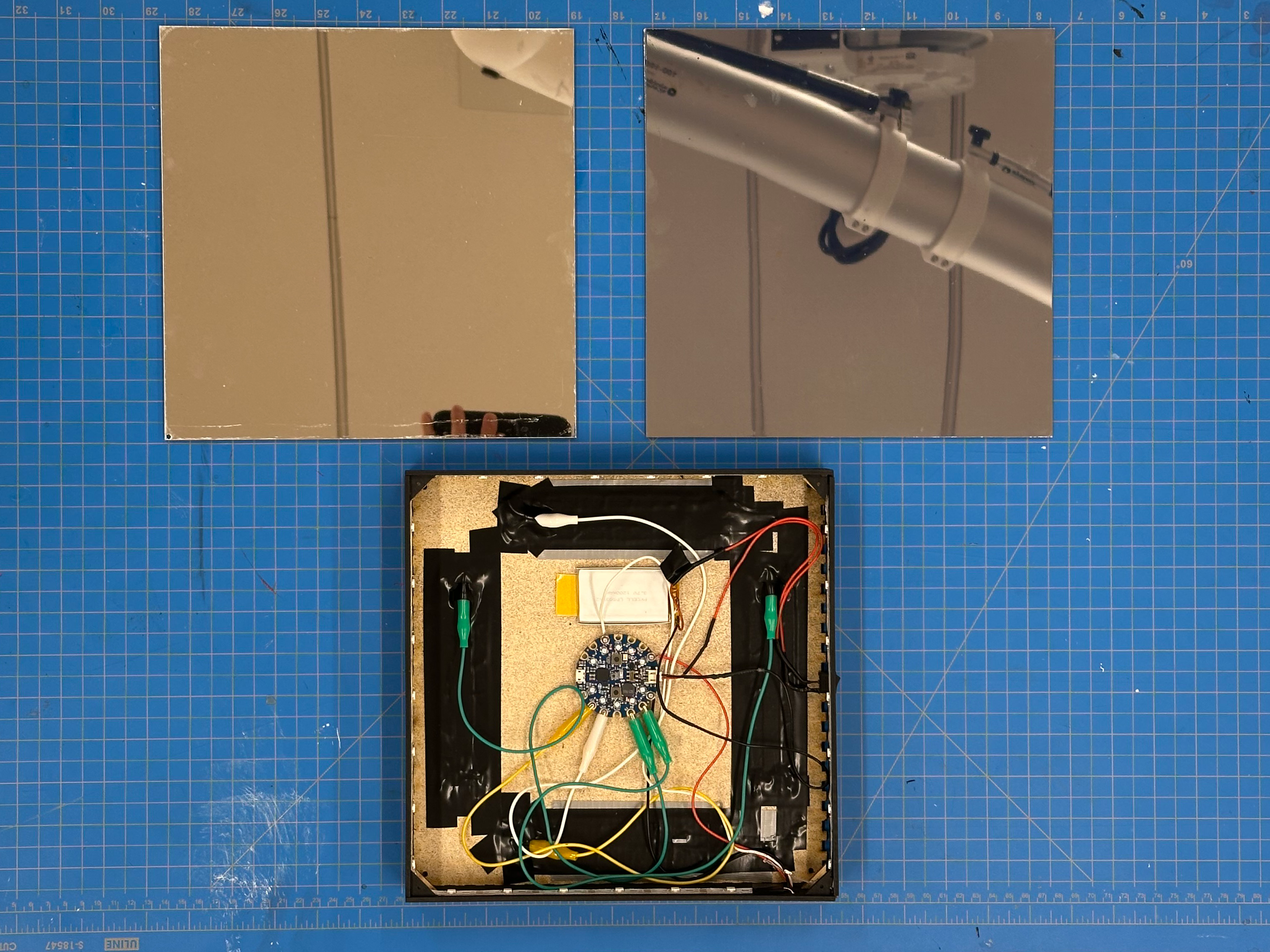
Materials for Circuitry
CircuitPlayground Bluefruit by Adafruit
Adafruit NeoPixel Digital RGB LED Strip - White 30 LED 3m - WHITE
Conductive Metal Tape - (Copper tape works well, but other alternatives are good too)
Alligator Clips x4
Soldering Supplies (Solder, Flux, Soldering Iron, Heat Shrink, etc.)
Red, White and Black Wire
Small On/Off Rocker Switch
3x M3 Screw and 3x M3 Nut
Materials for Laser Cut Box
1/8" (3mm) Mirrored Acrylic
1/8" (3mm) Two-Way Mirrored Acrylic OR (1/8" (3mm) Clear Acrylic and Two Way Mirror Foil)
Sheet of 1/8" (3mm) Baltic Birch Wood
Black Spray Paint (or color of your choosing)
Set Up Your Circuit Playground
)
Before we begin constructing our box, I recommend setting up your CircuitPlayground board. I followed the video linked by Prof. G. Once you've set up your circuitplayground come back to here!
NOTE: You may need to update the bootloader version on your board BEFORE dragging in a new .uf2 file. How to do this is linked here
Making Our Box
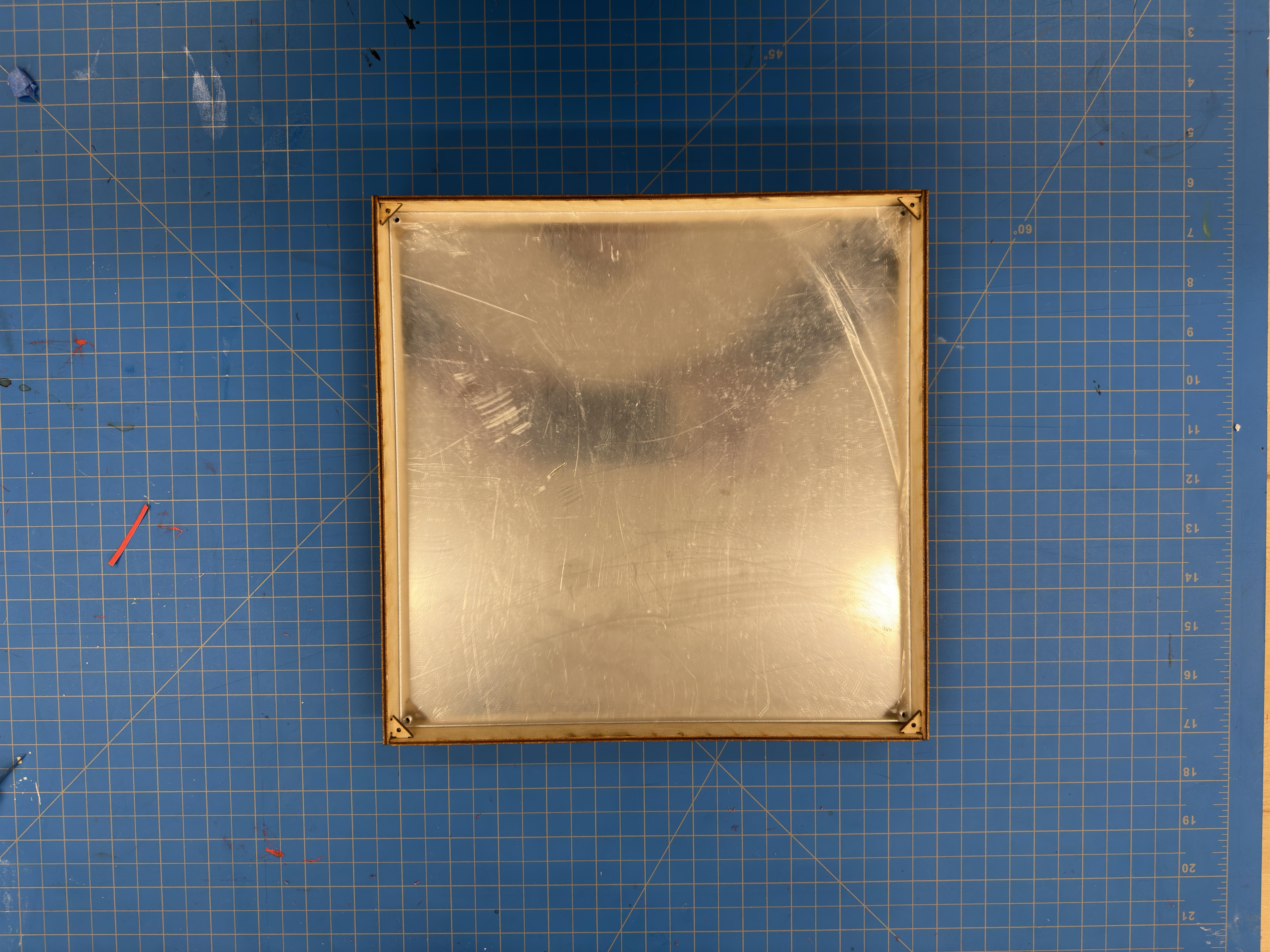
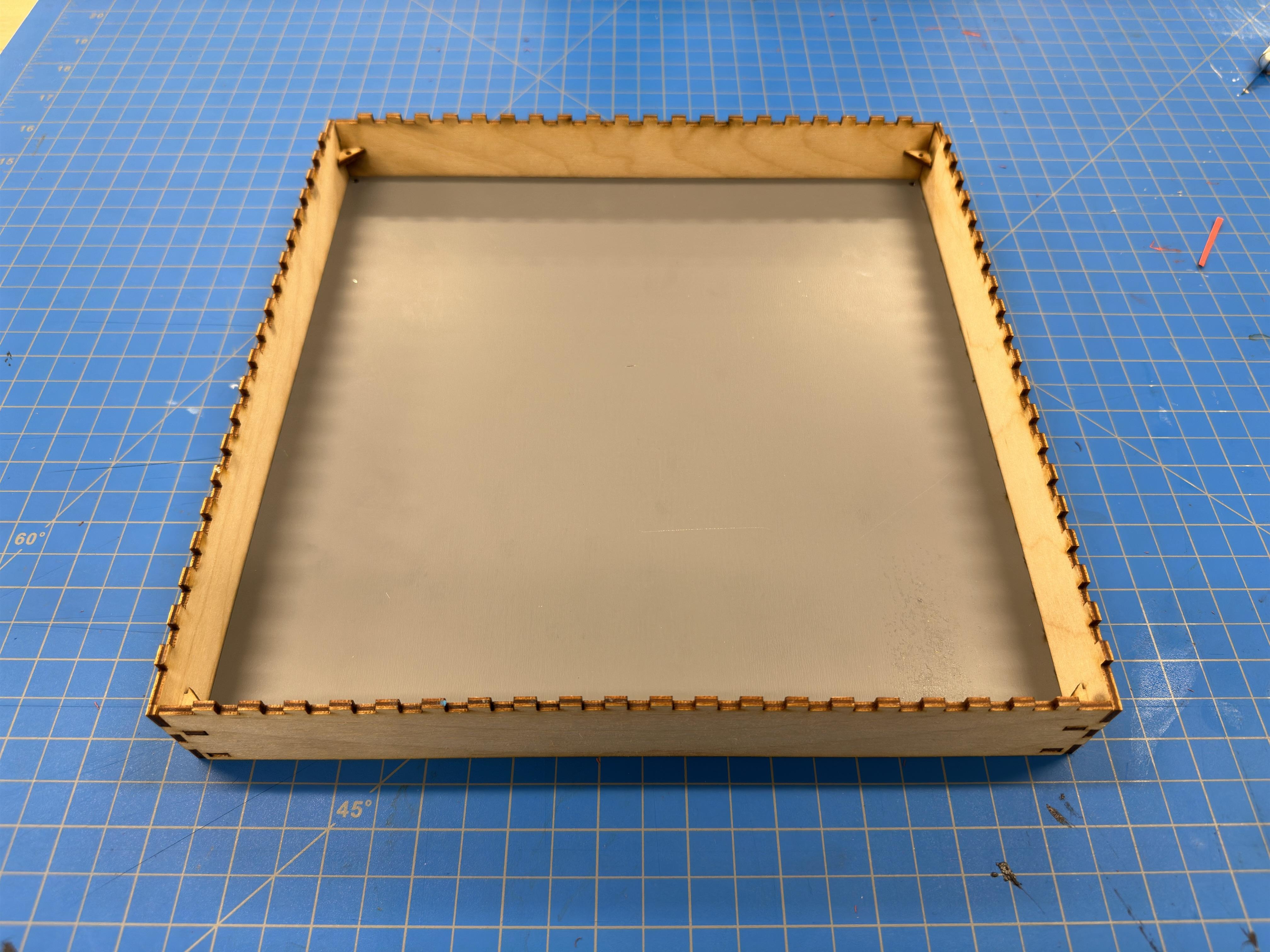
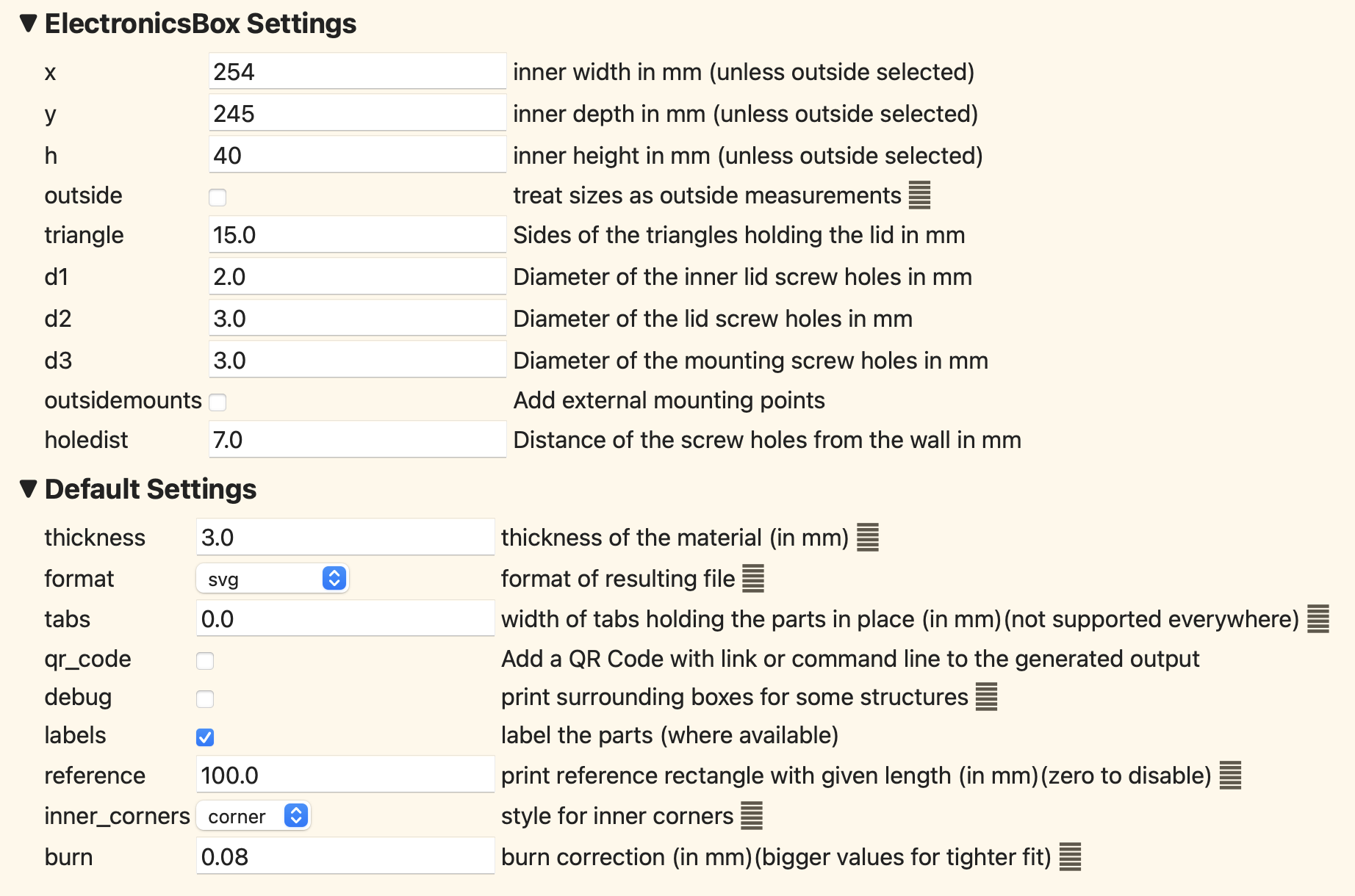
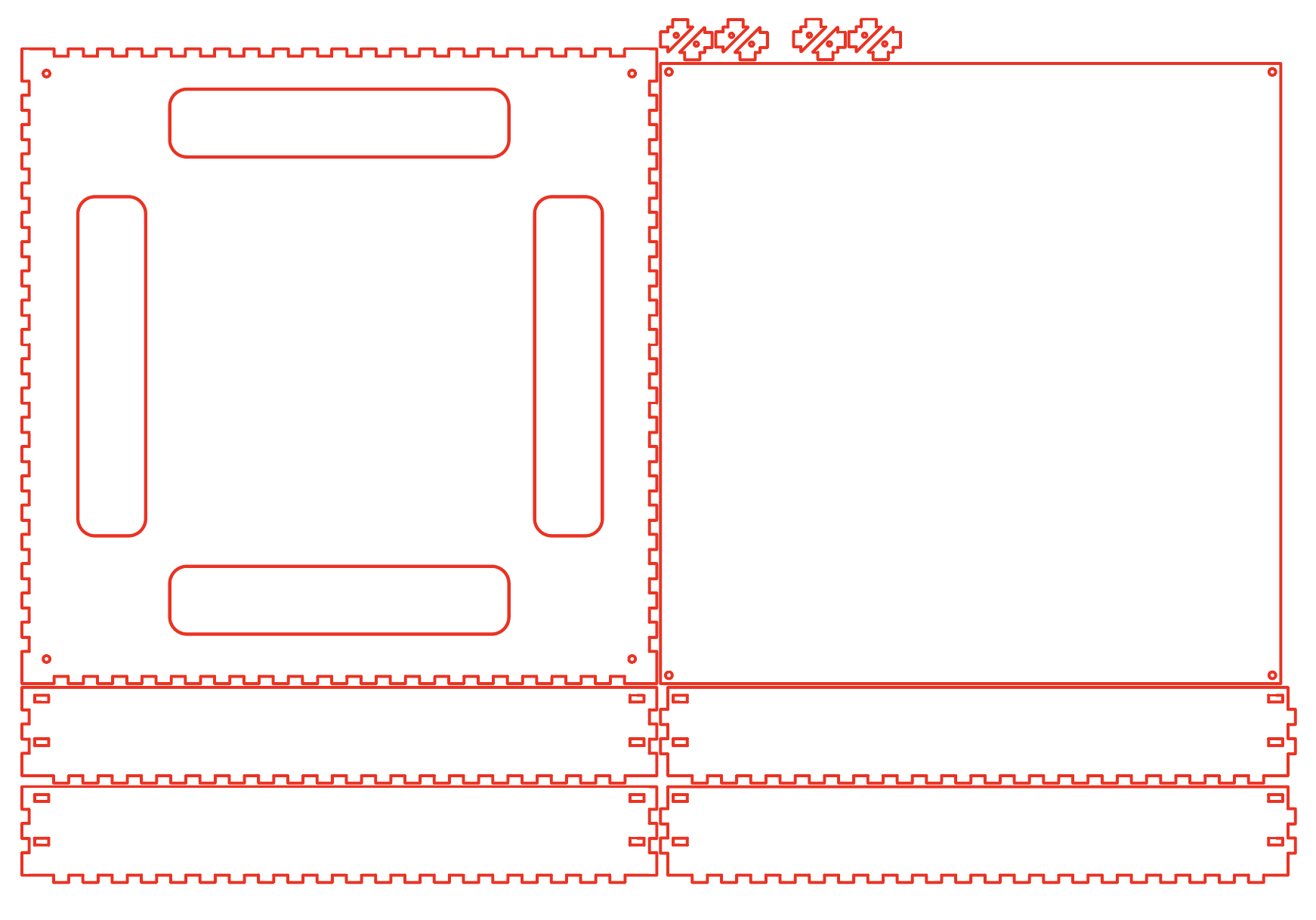
To create your box, you need access to a laser cutter. As mentioned before, there are also companies that offer on-demand laser cutting services such as makerstock.com but feel free to choose whatever company you prefer! To create the file ready to laser cut, (in theme with being python-powered) I used a website called boxes.py and used their "electronics box template". The exact settings I used are in an image above.
Note: You may want to change the "burn" value depending on what alser cutter you are using. I set mine to 0.08, as we will also be adding spray paint. Here a looser fit for your box is probably better.
Once we've downloaded the resultant .svg file, I put it into Adobe Illustrator (any vector based softare works as well) to add some key features. I addded a hole the size of my switch on one of the sides, I also added two holes above each other for cable routing towards the right edge of one of the sides. You want these holes to be large enough to route the wires from the Led strip around and under the mirror. Refer to the image above what I mean here.
Now you're ready to laser-cut your box!
Now we can spray paint our box. I decided to paint front and back of the sides and only one side of the bottom section. Painting the inside of the box amplifies the effect of the LEDs at the end!
Once dry, assemble the box which should look something like in the images above. No need to add the acrylic or two-way mirror yet! Now, we're on to the circuitry!
Download the .ai file for the laser cut box here ↓ (Note: this doesnt have cutouts for the switch or cable routing)
Downloads
Adding in the Circuitry

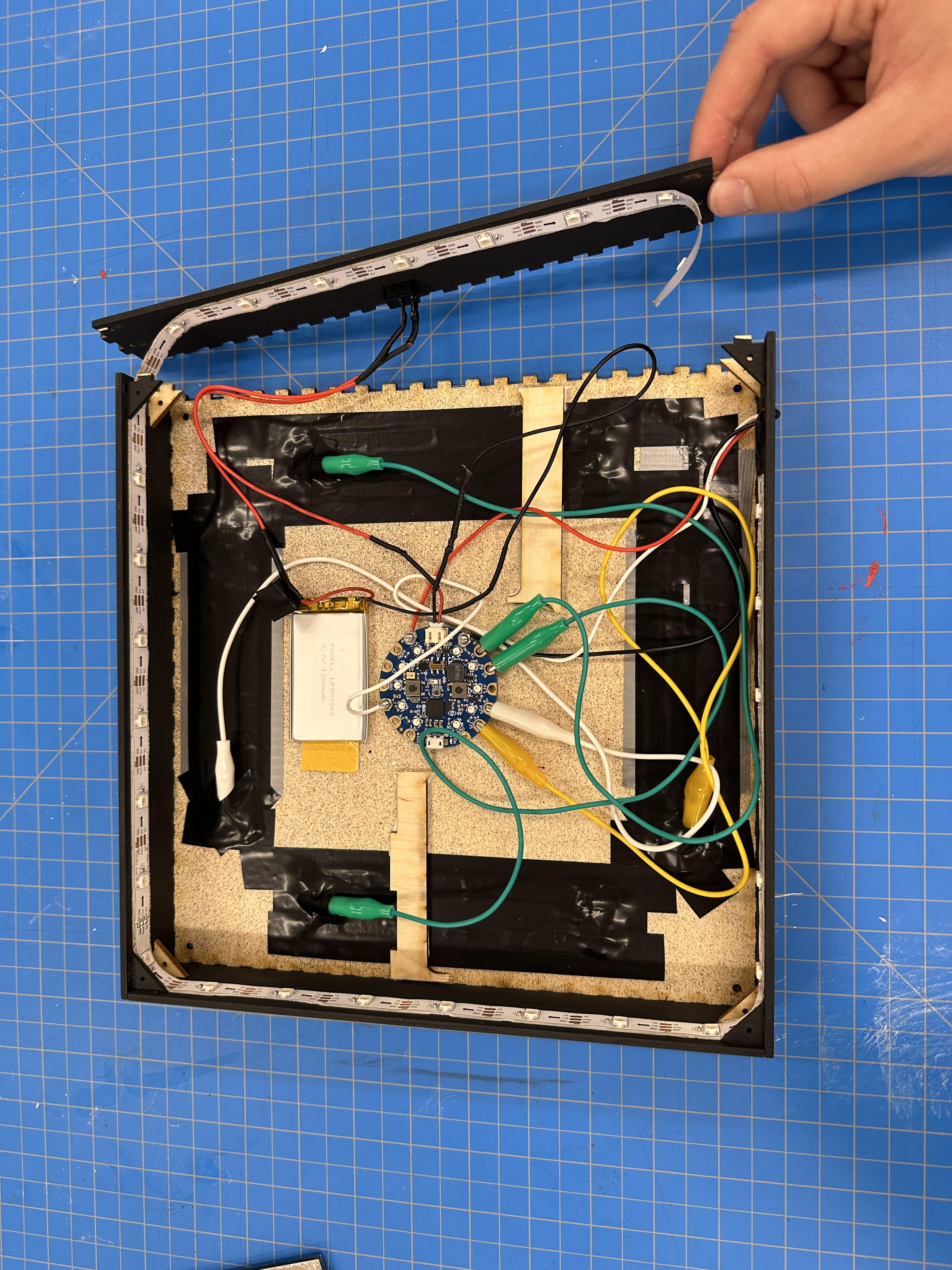
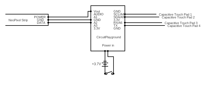
The first and most consequential step is putting our LED strip into the box. Carefully using a pair of scissors, remove the weatherproof coating from the NeoPixel strip. From there, add double-sided tape to the back of your LED strip. I had to cut my LEDs because 2m versions of the strip were unavailable. Regardless, the LEDs will need to fit around the inner perimeter of the box.
Stick the LEDs right under the first set of triangular holders. It should look something like in the image above. Begin placing the LEDs ~1inch from one of the edges and wrap clockwise (in reality this doesn't matter aesthetically, but this will affect the code). Then cut one of the wires on the LiPo battery and connect in the switch using solder. Then wrap the wooden cutouts from the bottom in the box in conductive tape leaving enough room to connect an alligator clip later.
IMPORTANT: make sure to leave enough slack on all of the wires to be able to open one side of the box and slide in the mirror later
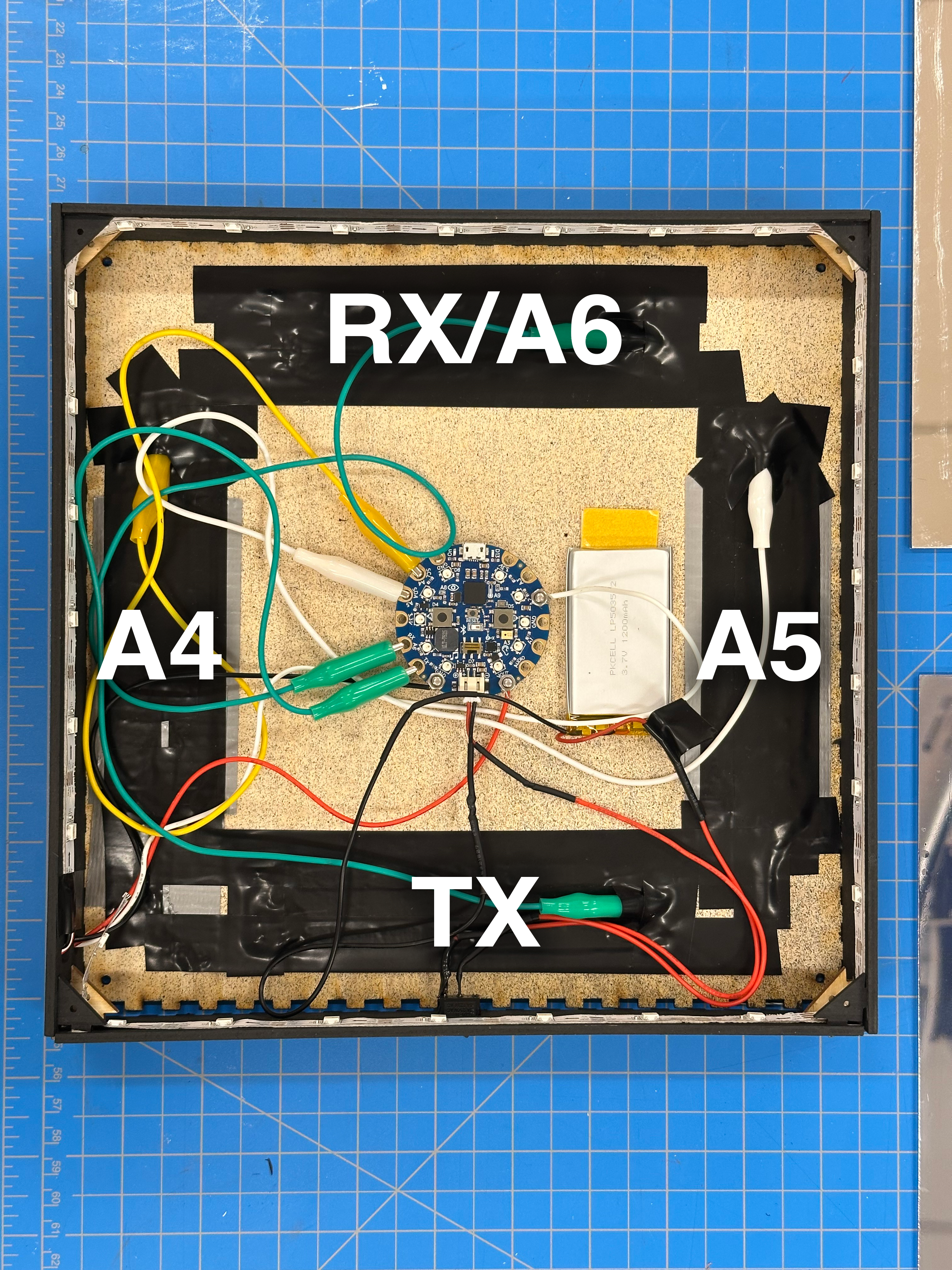
Now connect your capacitive touch pads to your CPB. I connected them as shown in the image.
Before sliding in the mirror let's upload the code!
CircuitPython Code
I've attached the code below. Some key features of the code include:
Touchpad Functions
Here, using the modulo operator, we are cylcing through a previosly defined set of colors in the matrix 'colors'. Where touchpad A4 moves forward in the set, and A5 back.
Another key feature is the mapping of accelerometer values to move an LED along the strip. This is done by the function 'accel_to_led' which converts accelerometer values to the led number to light up.
Using the atan2 fuction from the math library, we can convert our X and Y values from the acceleometer to an angle. However, as atan2 outputs values from 0 to 180 and -180 to 0, we modify this by making sure that when degrees < 0, we change the value to degrees = 180 + (180 + degrees). This gives us a angle in degrees from 0 to 360, which is then mapped onto the 29 Leds of the strip doing the following: led = int((360-degrees) * 1 / 360 * 29) - 1, as the set of numbers in 'strip' is 0 indexed, we subtract 1 from the final result.
Following this there is also a need to adjust the calue of the led, as when we are at 0 degrees, we don't exactly line up with the strip[0]. So I added + 3 to move the light over and then also manually adjusted the leds that would be bigger than the index allows.
The full code is attached here:
Downloads
Final Assembly
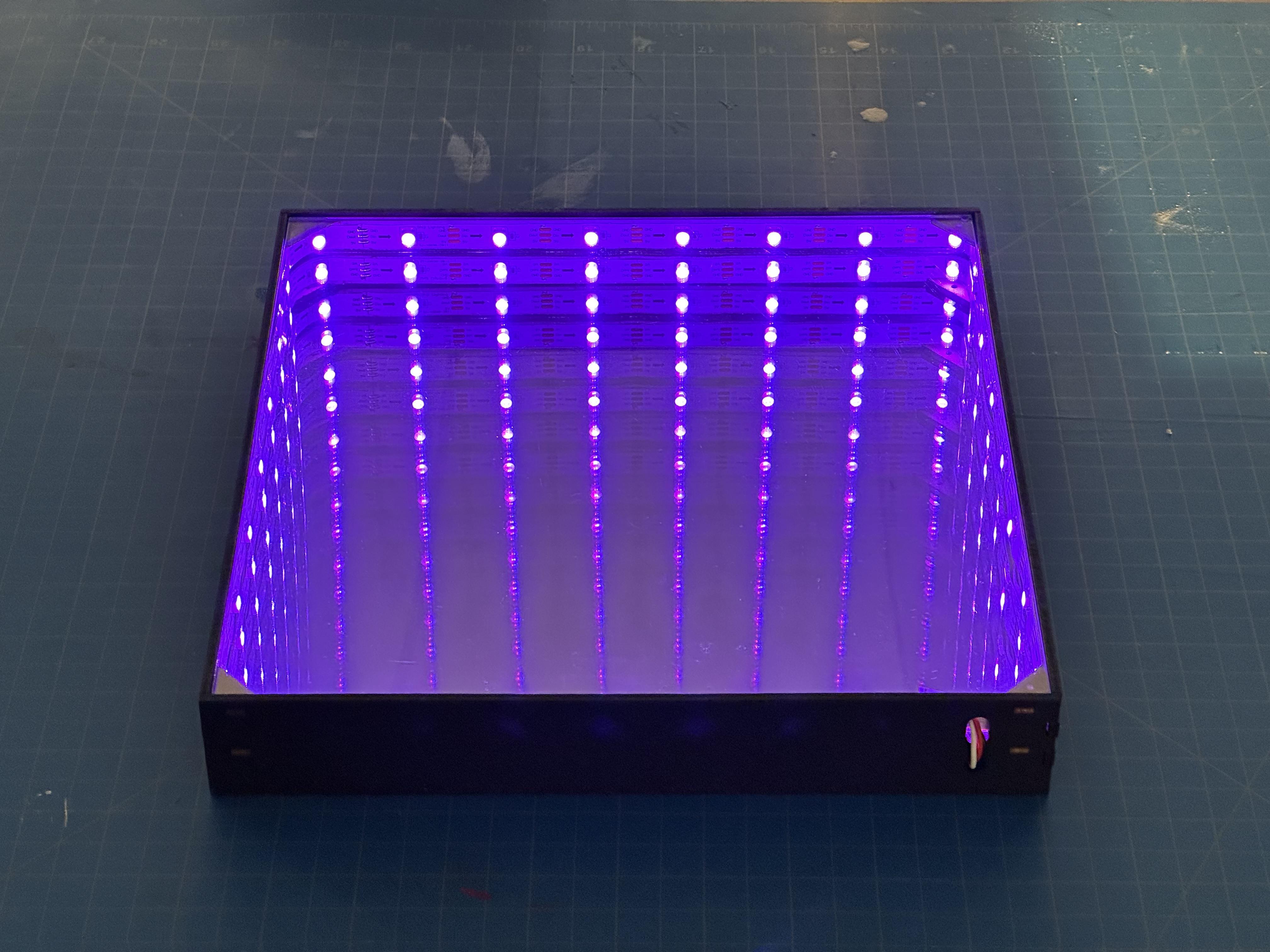
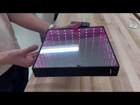
Now we're ready to assemble! Slide in the one sided mirror on the bottom level, and close the box. You may want to glue or fimly close your box. Then lay the two-way mirror on the top, this should be a snug fit, but you may want to add glue in the corners.
And there you go! You have an interactive infinity mirror!
Thanks for following along with the instructable. You should get a result similar to what I show in the video above.