Toothbrush Timer
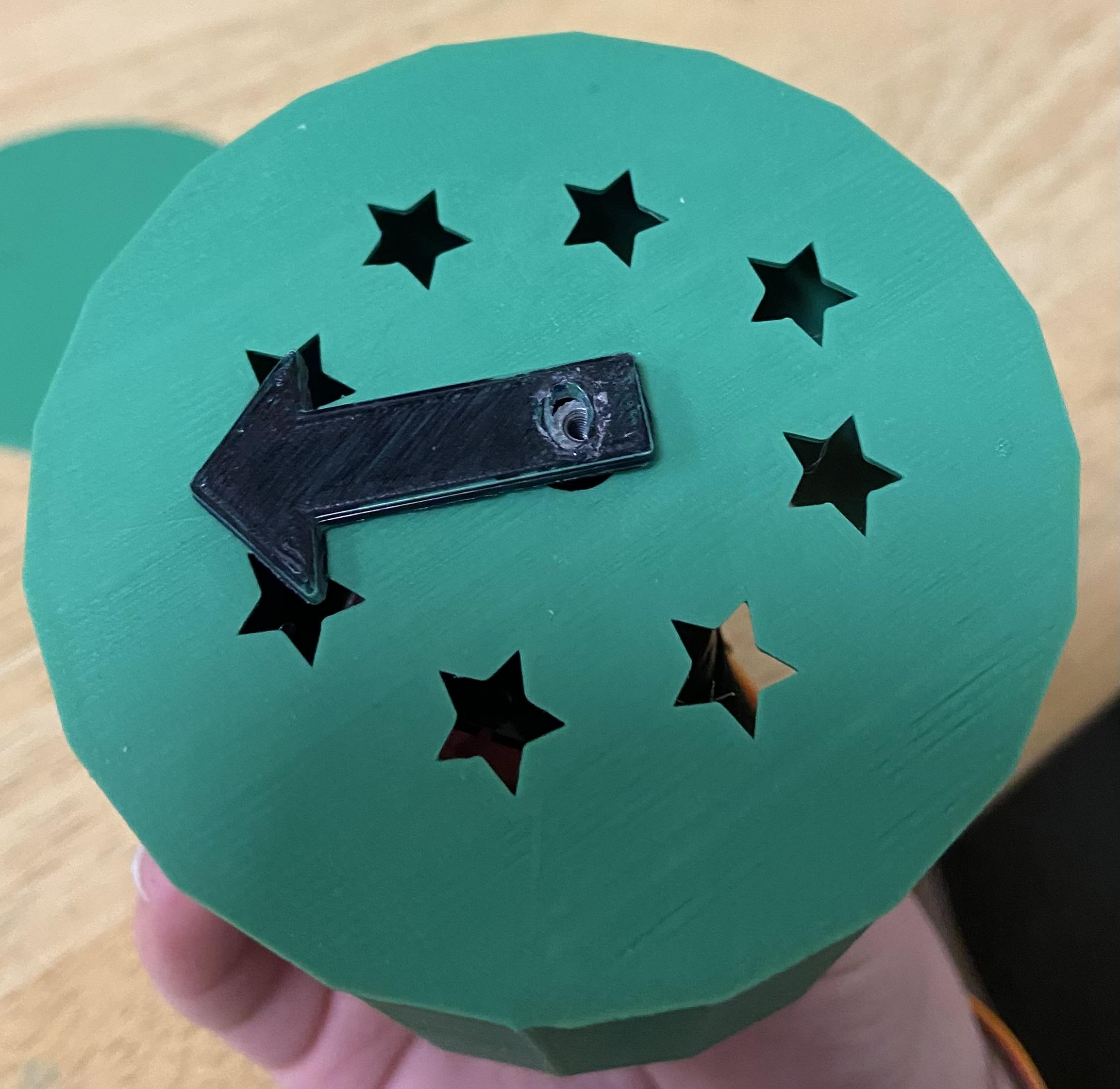
We are engineering Python code to make a Circuit Playground Express perform 3 different functions, sound, motion, and light. In the end, we will have produced a functional 2-minute timer that can be used for brushing teeth.
Supplies
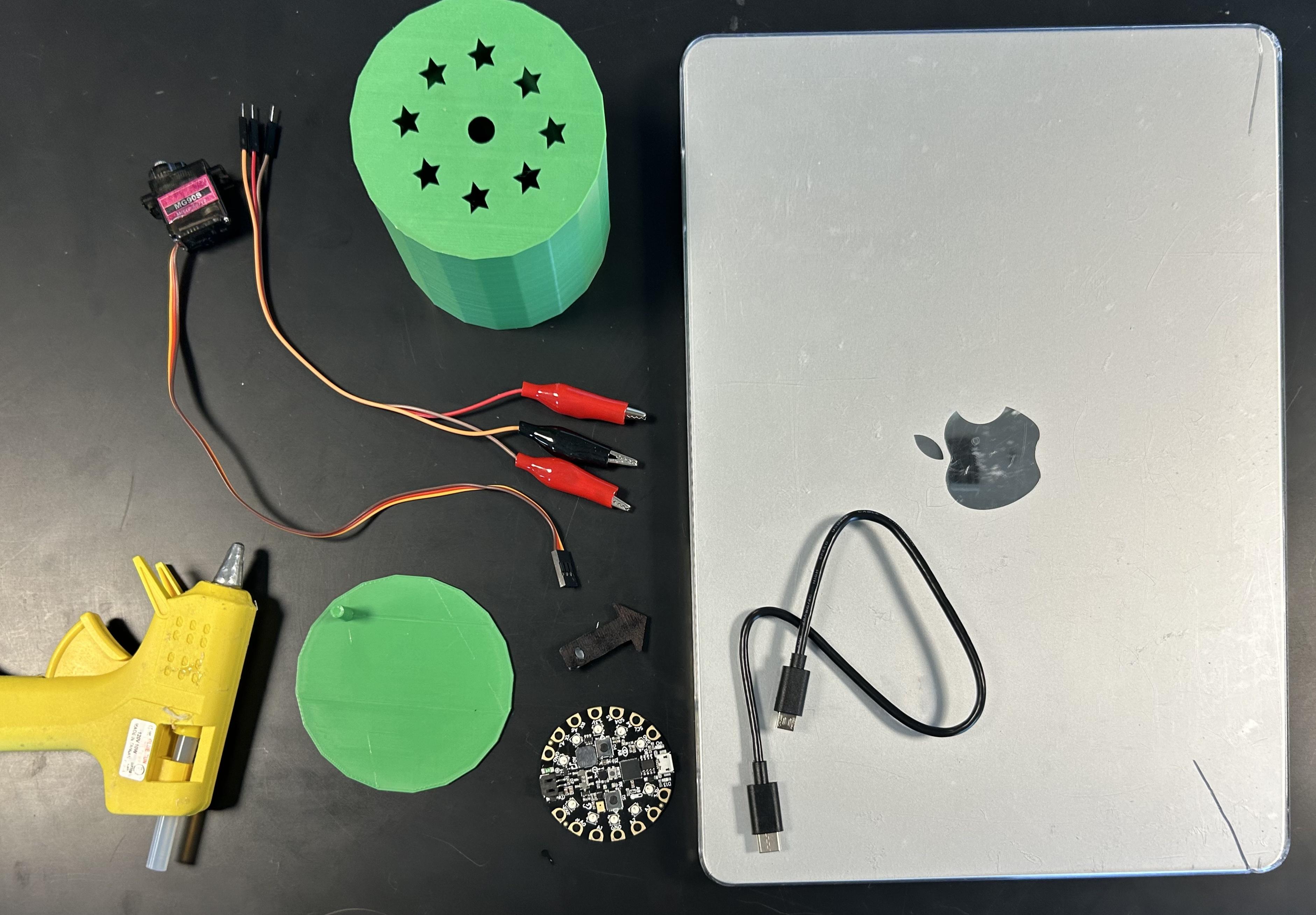
CPX (Circuit Playground Express)
Computer
USB-C or USB-A
Codes from the Circuit Python website
MU Editor
Continuous servo motor
Alligator clips with wires
3D Printed Design
Hot Glue Gun
Overview of Circuit Python
Here is a link to Adafruit's website giving foundational information about our Circuit Python code: Adafruit Website.
Plug the CPX Into the Computer
Plug in the CPX using either a USB-A or USB-C cord to your computer.
Attach the Servo Motor to the CPX
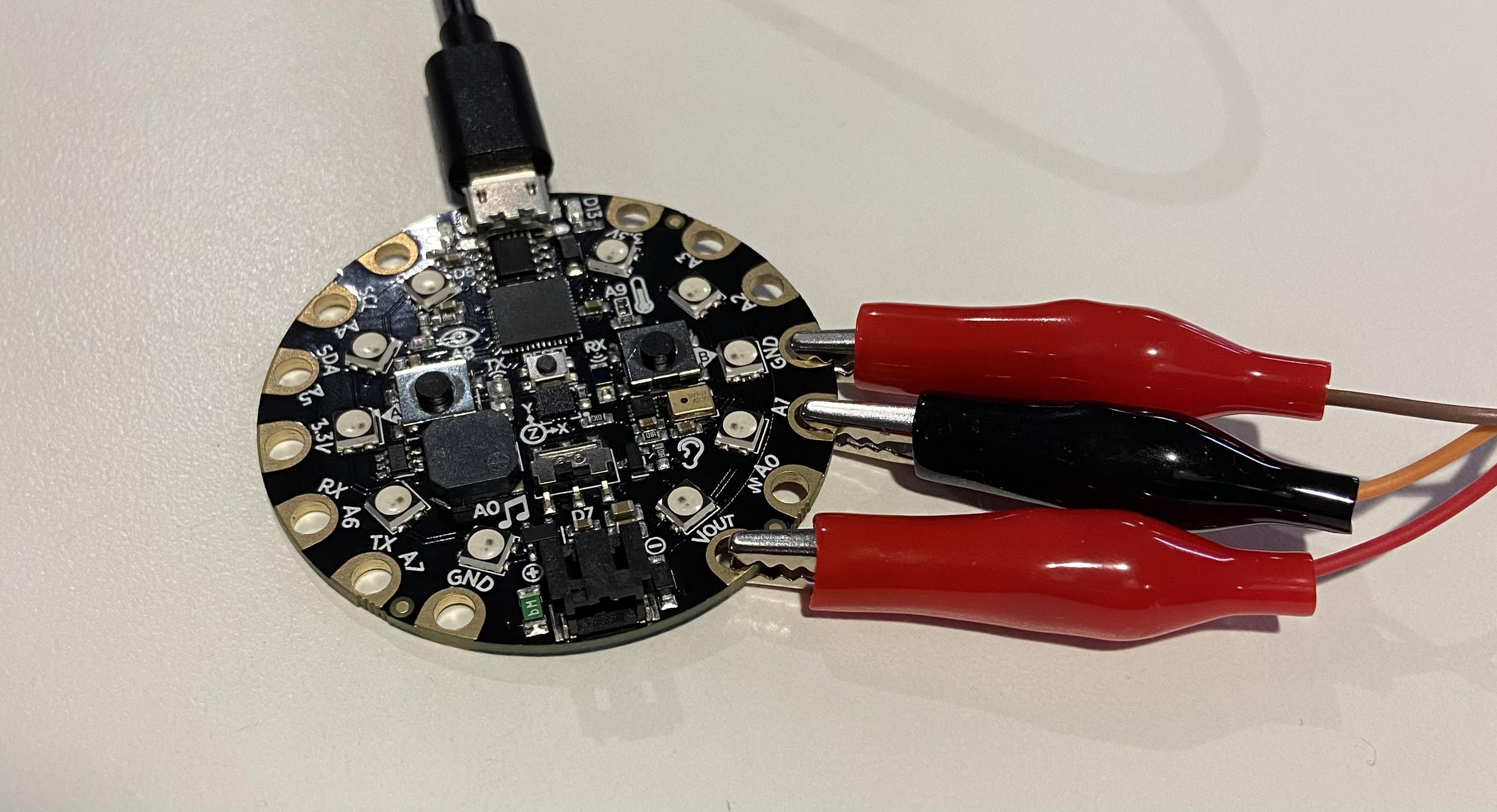
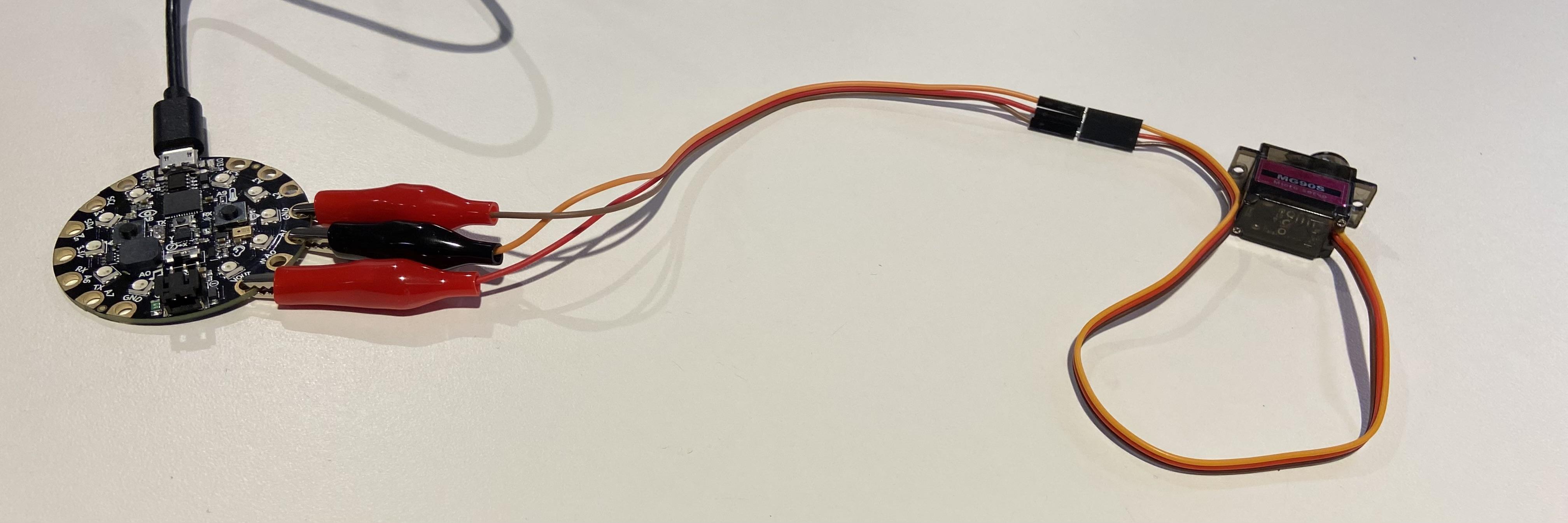
Using the alligator clips, attach the continuous servo motor to the CPX. Attach the brown wire to GND, the orange wire to A1 and the red wire to VOUT. Please reference the image attached.
Upload Code for the Servo Motor
Open up the MU Editor on your computer. Make sure you upload a blank code.py file onto MU Editor. Then open the attached file and copy and paste the entire code into the MU Editor.
Downloads
Upload Code for Lights
Open the attached file, copy the entire code for lights and paste it in the MU Editor below the code for the servo motor.
Downloads
Upload Code for Sound
Open the attached file, copy the entire code for sound and paste it in the MU Editor below the code for lights.
Downloads
Combine the Codes
The attached file consists of the combined codes, because in order for all functions to work simultaneously, we needed to combine the codes in a specific way.
In order to have all codes run at the same time, copy the entire combined code and paste it in a blank code.py file in the MU Editor.
Downloads
Print the 3D Design
Assemble the Timer Pt. 1
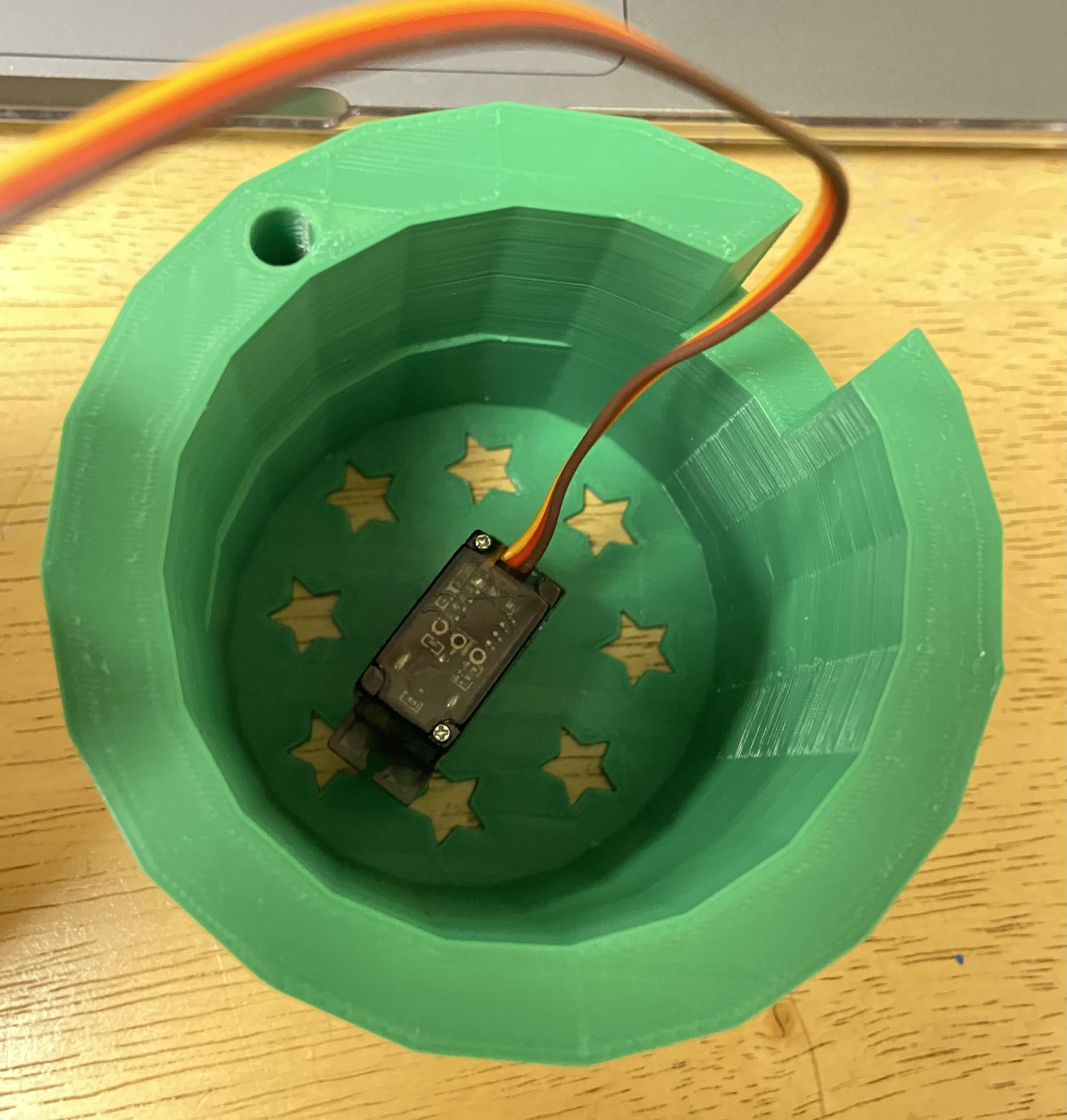
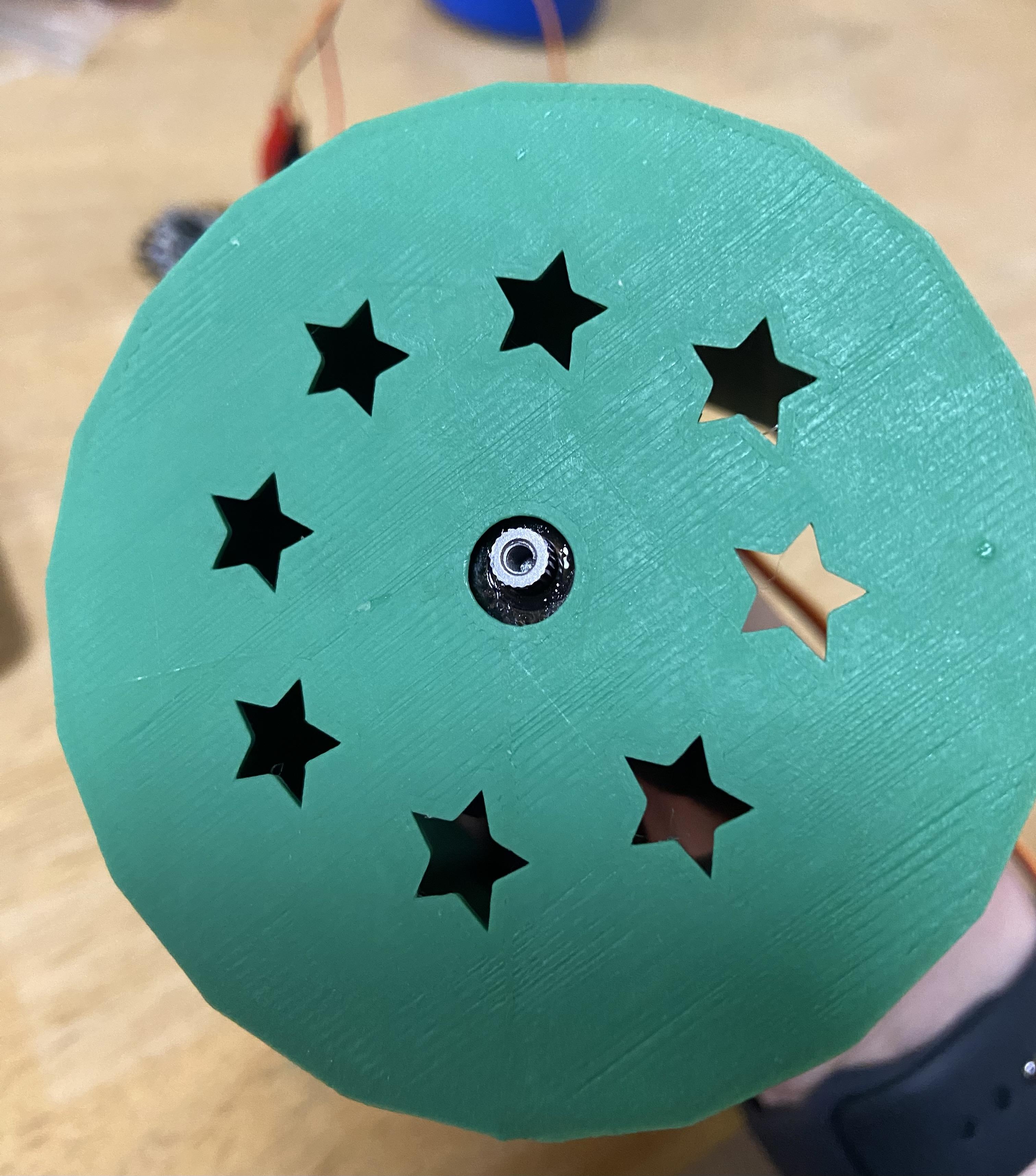
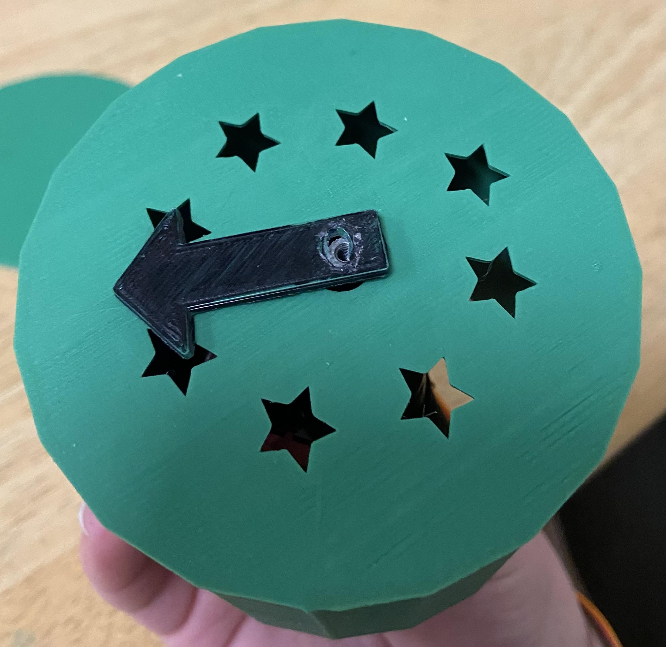
Once all three codes are uploaded into the MU Editor, hot glue the servo inside the base of the timer through the hole and attach the arrow on top.
Assemble the Timer Pt. 2
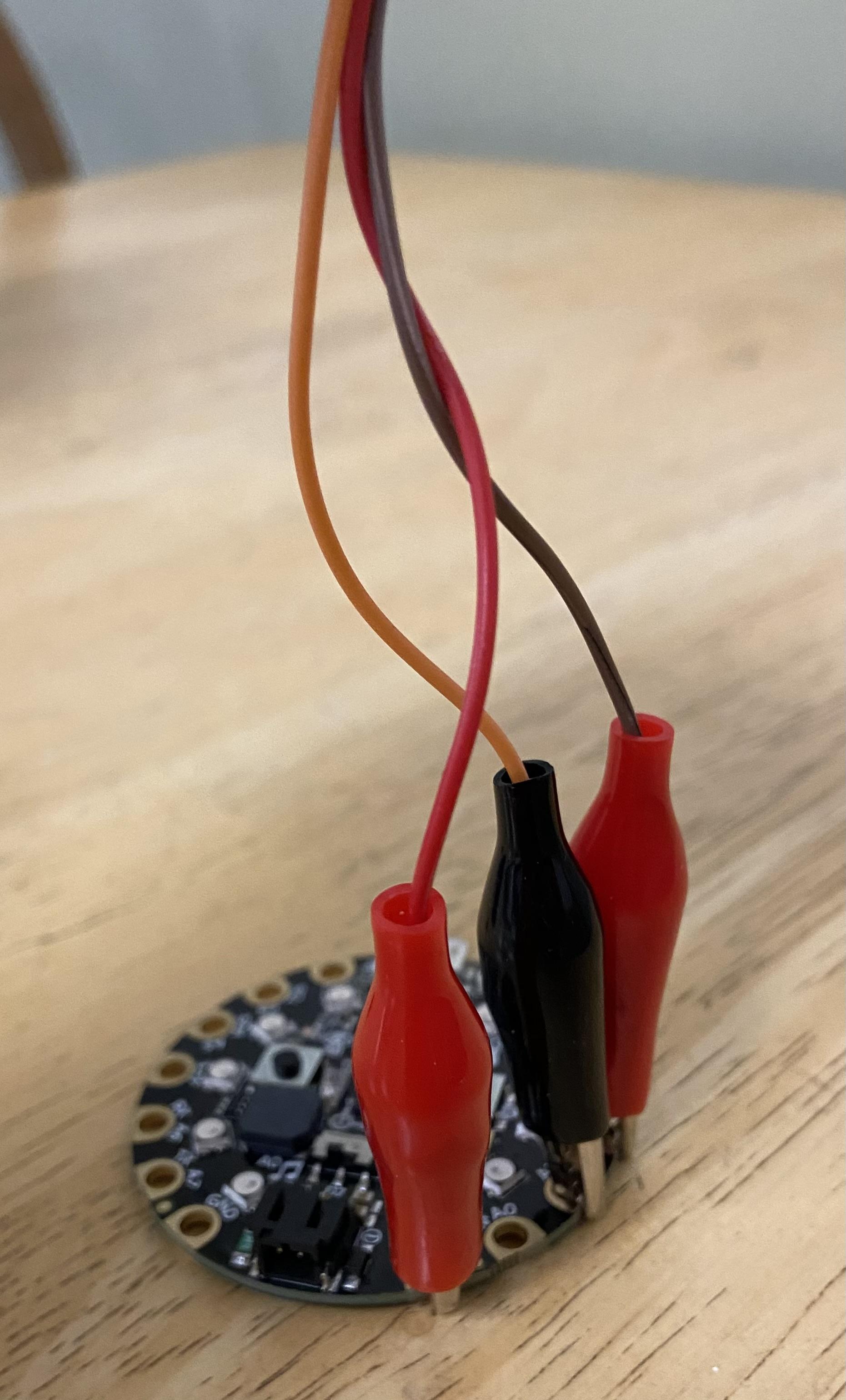
Insert the wires and the CPX inside of the timer in the same way the image shows above. Make sure the CPX wire connected to the computer goes out the side opening. Then attach the bottom lid to the timer.
Save the Design
By pressing the "Save" button on the MU Editor, the timer should start to work!