Chronobot : a Clever Alarm Clock
by Paranoid Legend in Circuits > Clocks
22334 Views, 99 Favorites, 0 Comments
Chronobot : a Clever Alarm Clock
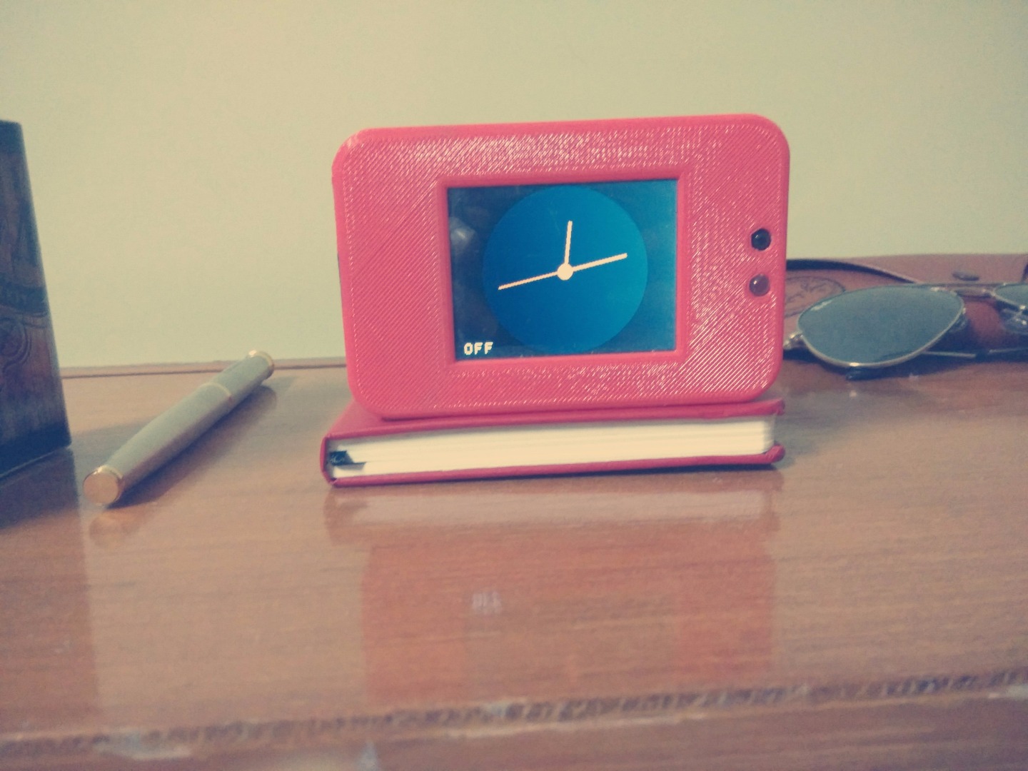

Chronobot is a clever alarm clock that can sense its own orientation. It is an analog clock with an awesome looking case. The clock is fairly easy to build and set up. It's been made using an ardunio mini and a TFT screen. Chronobot is customizable according to your preference of colors. It can be coded and charged without opening the case and can be charged through a micro USB port.
Some Cool Features :
-The alarm can be switched ON/OFF by simply changing the orientation of the clock!
- It can be coded without opening the case.
- It can be charged through a micro USB port.
- It senses your presence! (Thus saving power when no one is around)
- It is no bigger than an small table clock!
Please share and change it as you like. Please post any questions that you have in the comment section.
Components Required
1. Arduino Pro Mini 3.3V
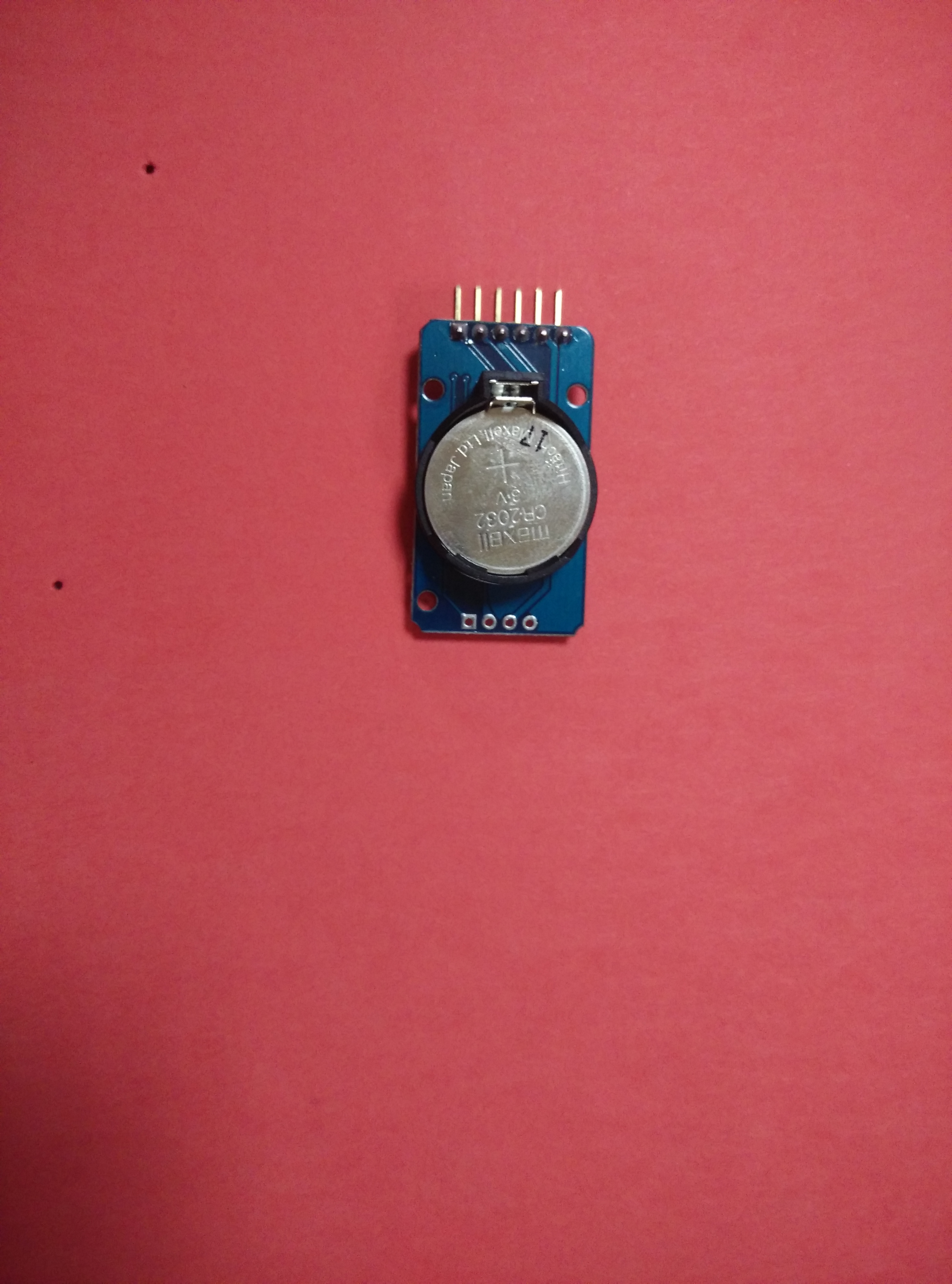
2. DS3231RTC module
3. 2.4 inch TFT Screen
4. 3.3 V Nokia BL-5C battery
5. Chargin IC with Micro USB Port.
6. Switch
7. IR Obstacle detection Sensor
8. Buzzer
9. Wires
10. Female Berg Connectors
11. Arduino UNO (Optional)
Coding the RTC
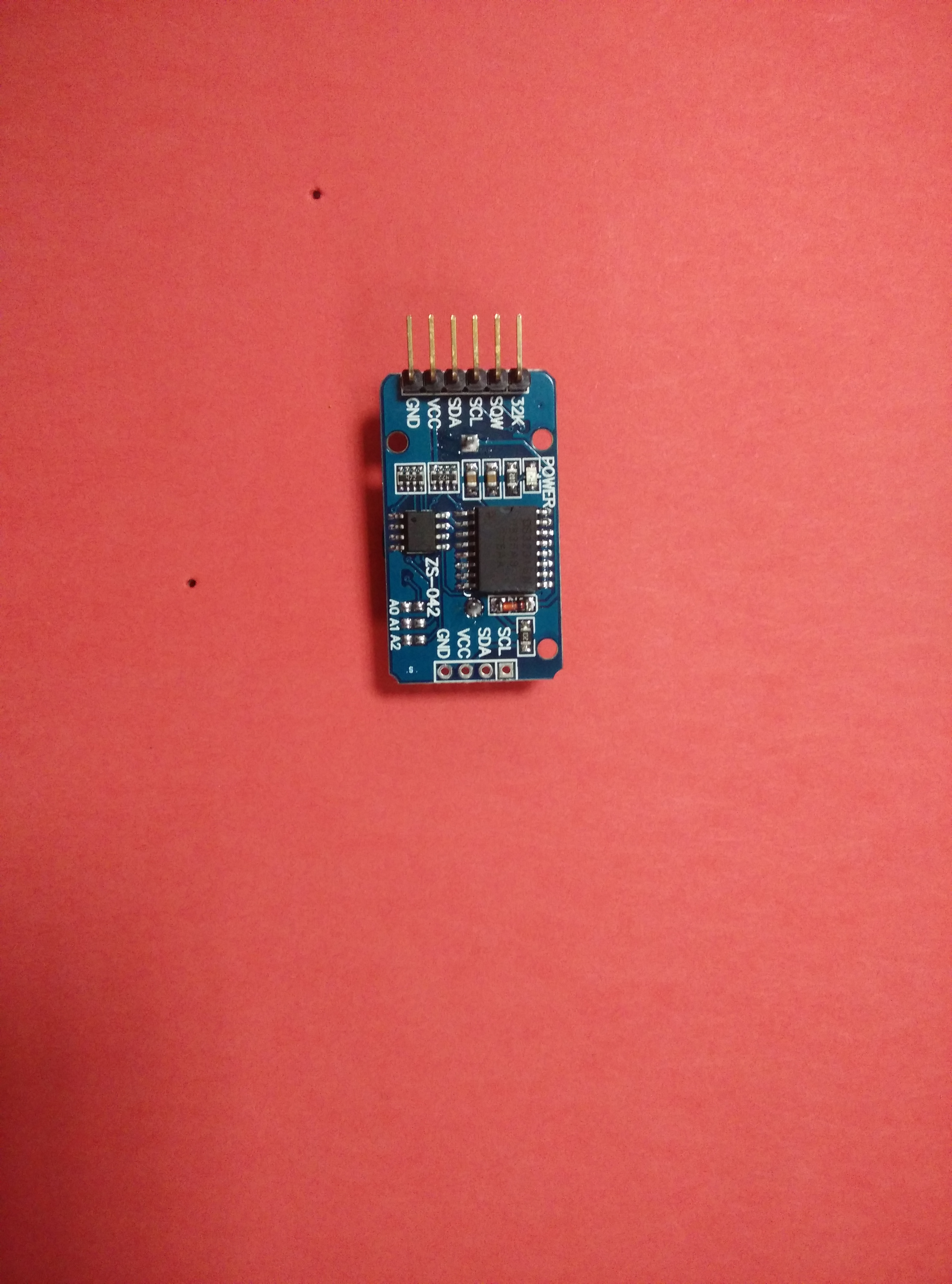
The RTC module needs to be set with the correct time. Make the following connections with the arduino:
SCL → A5
SDA → A4
VCC → 3.3V
GND → GND
Download the DS3231_TEXT.rar file given below. It contains the library required for the RTC module. Extract it and place the it in libraries folder in the root arduino folder.
Then run the given code using the ardunio software. It will load the RTC with the current system time. To verify check the Serial Monitor and set the baud rate to 115200.
You will need to run this code each time you want to set the RTC time.
Check the TFT Screen
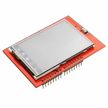

If you got a TFT shield like I did, this part will be easy. Since the library has been altered, the LCD_D2 should be connect to Pin 10 and LCD_D3 should be connected to Pin 11, you can do this using wires. Download the libraries given below, place them in the libraries folder of arduino root folder. Then run the example code in TFTNew library named graphicstest. The output should be the same as the video. For any help, leave a comment.
Note: I have modified the adafruit library and added a function that will help in coding the digital clock. Thus, the default library will not work in later stages.
Downloads
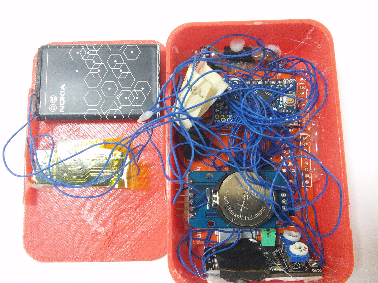
Solder the TFT and Arduino Pro Mini
This part is a little tricky. Remove the header pins from the TFT screen. This makes it less space consuming and since we are connecting it to an arduino Pro Mini we do not need them anyway. Now solder each pin of the TFT to the arduino Mini. Here is a quick reference:
LCD_RST -> RESET
LCD_RS -> A2
LCD_WR -> A1
LCD_RD -> A0
LCD_D2 -> 10
LCD_D3 -> 11
LCD_D4 -> 4
LCD_D5 -> 5
LCD_D6 -> 6
LCD_D7 -> 7
LCD_D0 -> 8
LCD_D1 -> 9
Note: The LCD_CS Pin is not required and therefore do not solder this pin. We will be using A3 as an output pin for buzzer later.
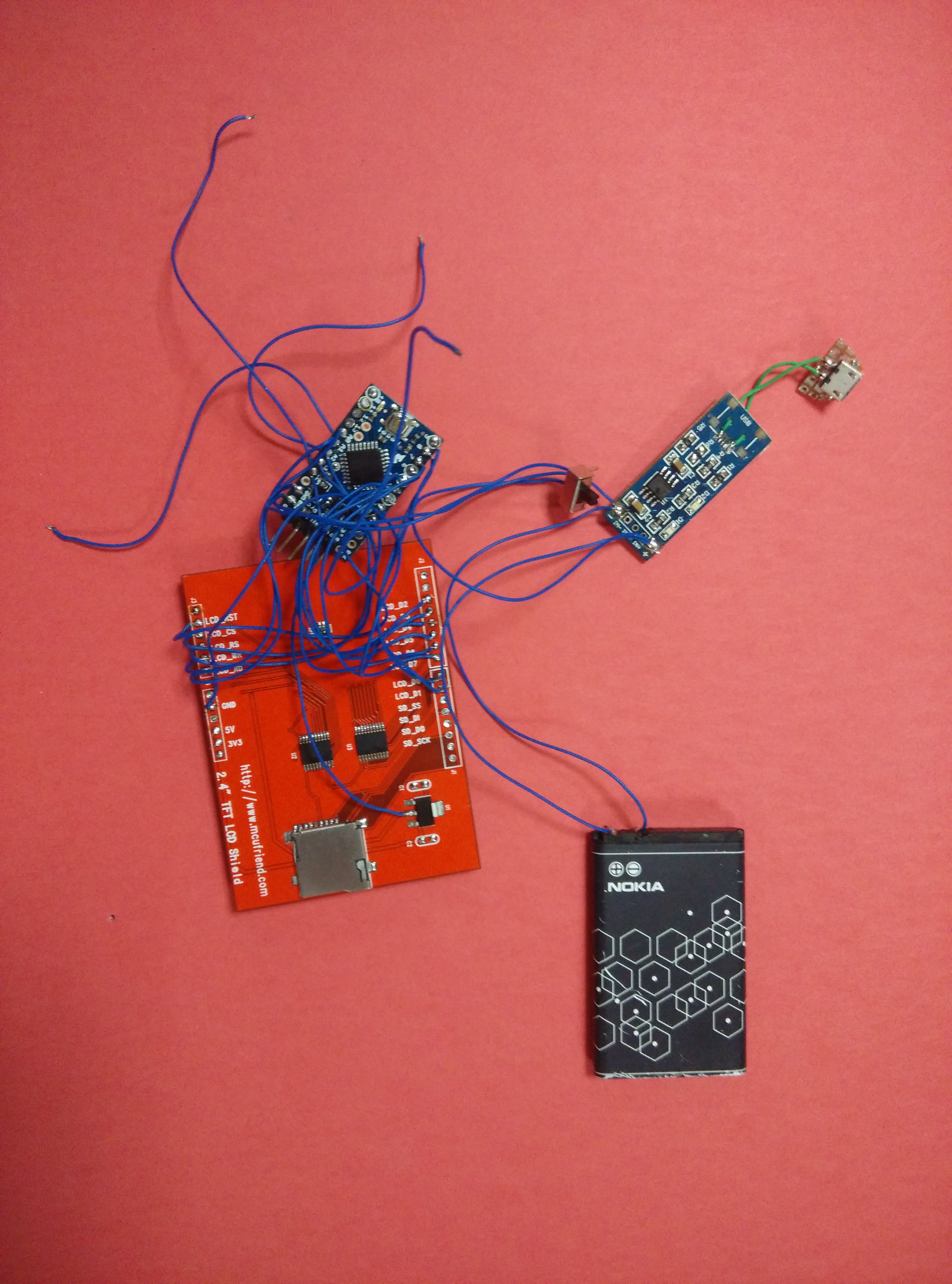
Solder the Battery, Charging IC and the Switch
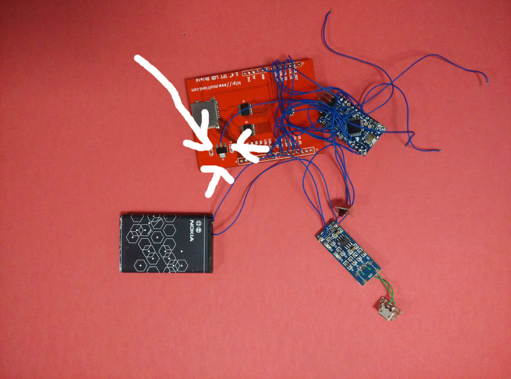
Solder the battery to the charging IC and the VCC and ground of the arduino with a switch. Also solder the 12 and 13 ports of the arduino directly to the level converter output on the TFT as shown in the picture. This will power the TFT screen. And solder the ground of the TFT screen to the common ground.
Solder the RTC
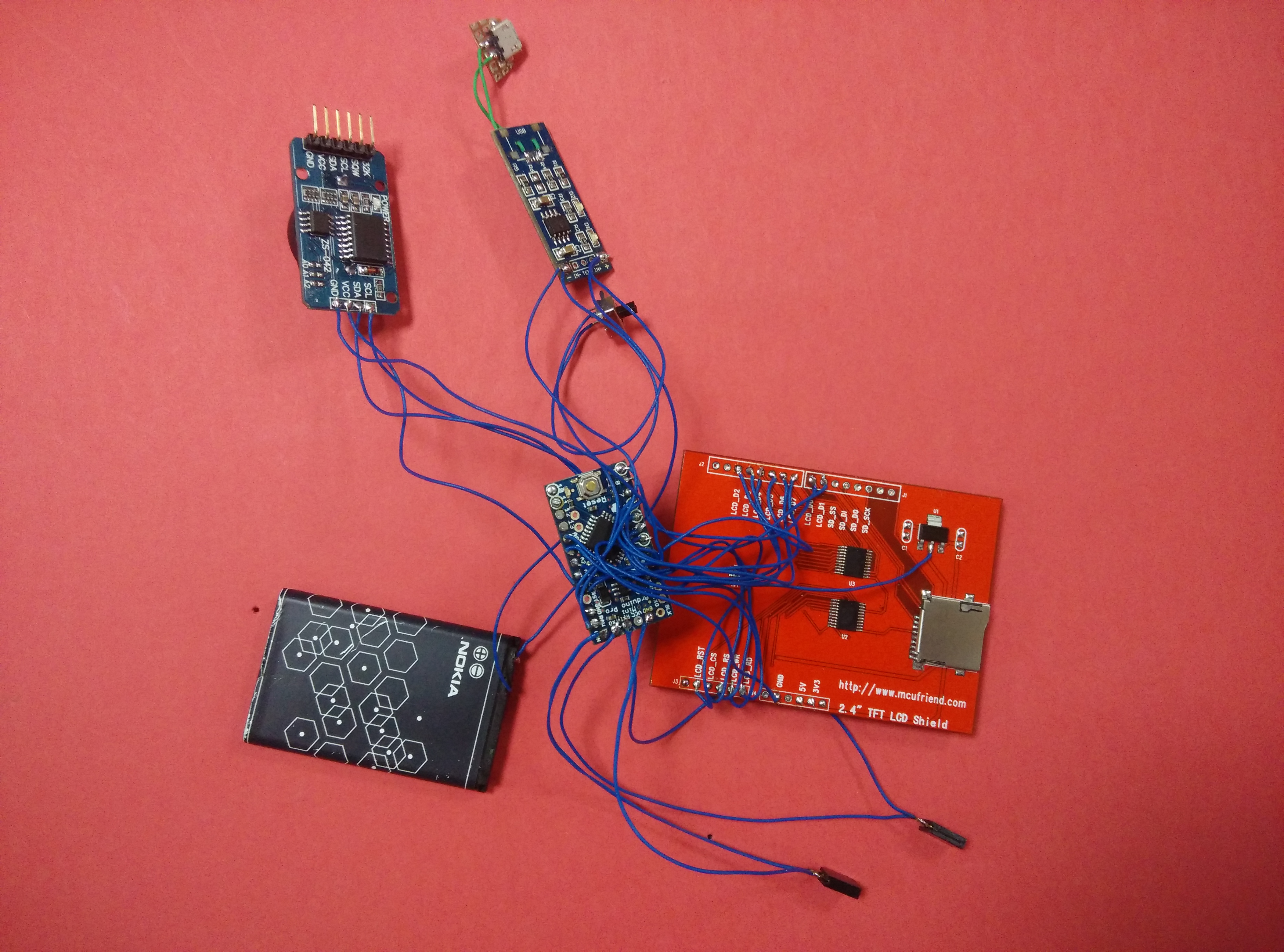
Solder the RTC to the arduino pro mini.
SCL → A5
SDA → A4
VCC → 3.3V
GND → GND
SQW -> 2
Solder the Berg Connectors
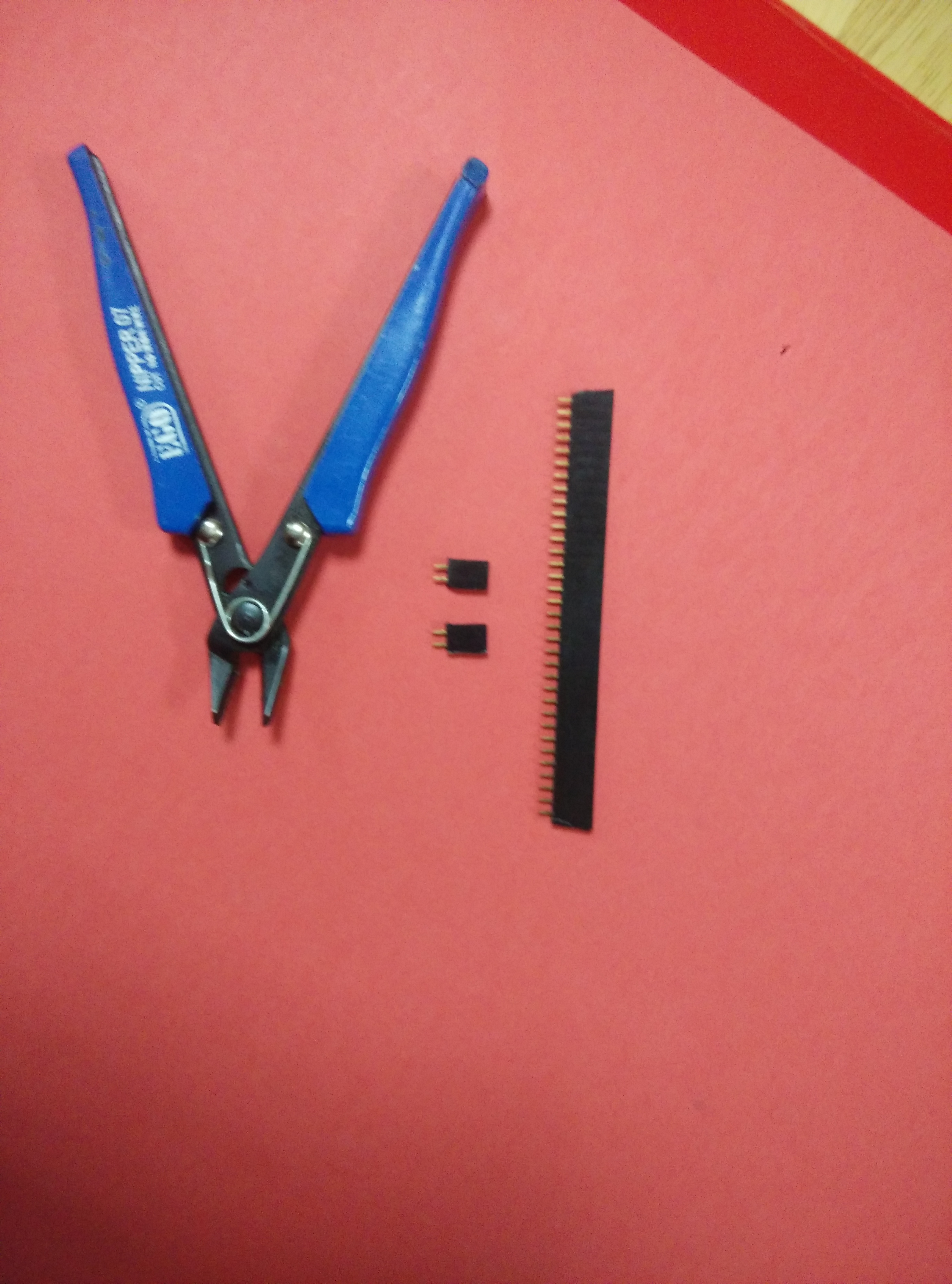
Connect the berg connectors to the following four pins of the arduino:
PIN 0
PIN 1
RESET
GROUND
These will make it easier to code the clock even after the case has been sealed shut.
Solder the IR Sensor

Solder the IR Sensor to the arduino. The VCC to 3.3 V battery. The ground to common ground. And O/P to pin 3. Tune the sensor to get the optimal sensing distance.
Solder the Ball Switch

Solder the two terminals of the ball switch to ground and A6.
3D Print the Case
You can download the STL files and 3D print the case in any color you want. The case features holes for the berg connectors and IR sensor.
- The case used in the clock was 3D printed using the makerBot Replicator 2.
Fit Everything Into the Case
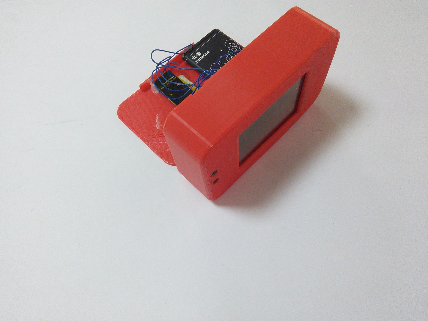
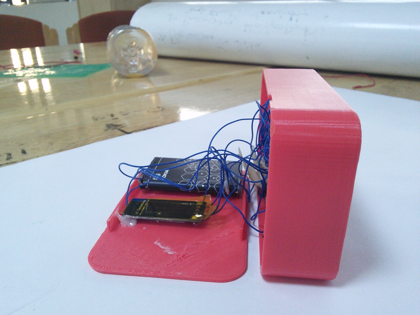
Fit everything into the case. The IR led and receiver go into the front panel holes. The berg connectors go into the side panel hole.Remember which pin is which for later use of the berg connector to code. The switch too should be glued just inside the slit so that the clock can be switched on or off using a pin. Glue everything using a glue gun or however you see fit.
Coding
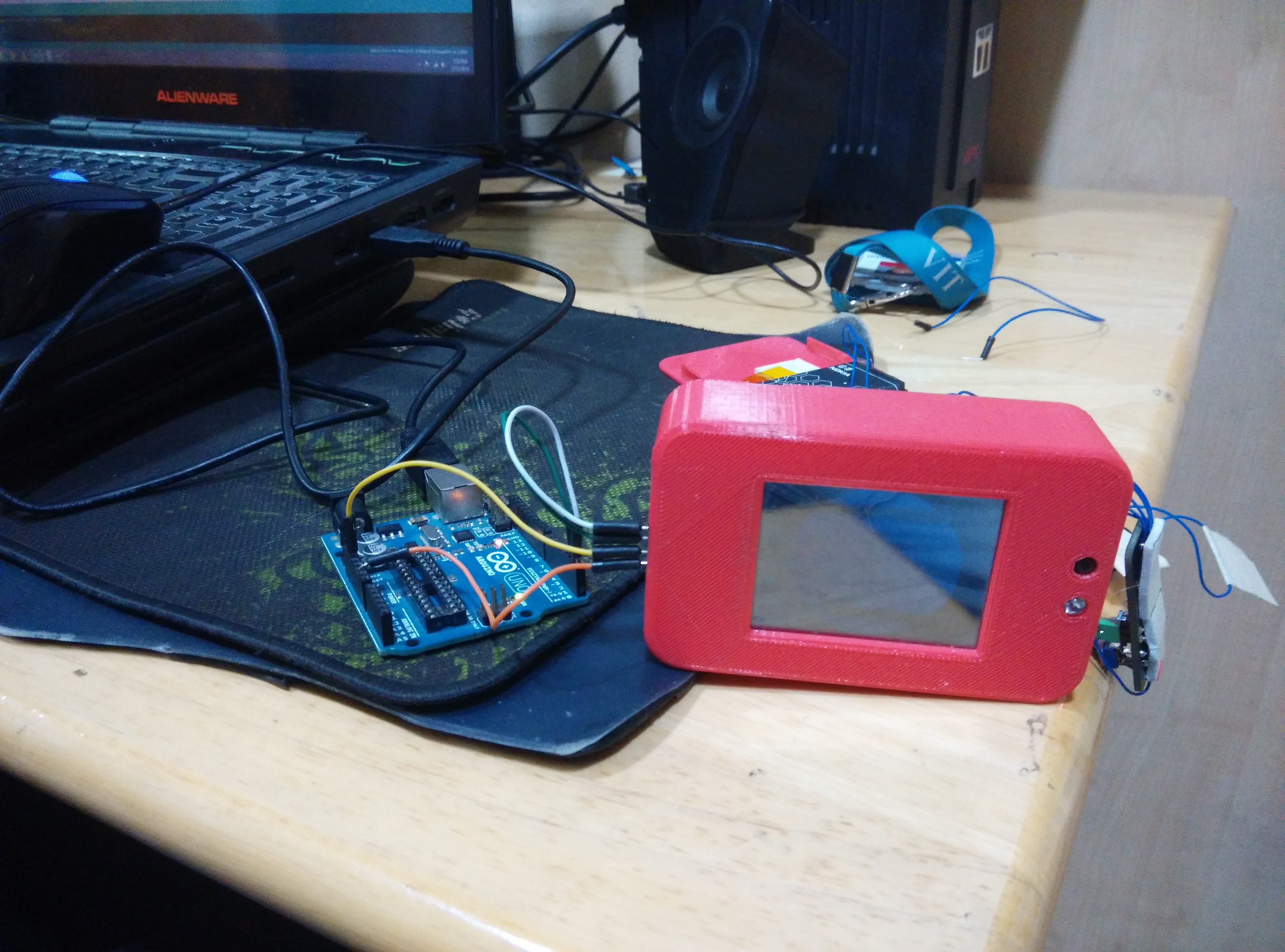
Upload the give code using the berg connectors and test the clock!! The alarm setting can be changed from the code. The colors can also be changed from the code, only they have to be in 16-bit format. If everything is good, seal the case using glue.
Downloads
DONE

Congrats!! You are now the proud owner of an awesome smart digital clock!! For any queries please drop a comment. Thank you. :)