Chrome Dino Charm Accessory

Hi.
I am a 2nd year Mechanical Engineering student at The Pan-Atlantic University, Ibeju-Lekki, Lagos, Nigeria.
I will be putting you through the process of creating a chrome dino charm you can wear as an accessory on your bags e.tc
Enjoy!
Supplies
For this project, you will need the following:
- The Fusion 360 software
- A reference image for the dino
- A CNC Machine/Router
- Stock Metal
Adding Reference Image and Making Your Sketch
.png)
.png)
Firstly, you load up Fusion 360 and create a new file for your model. Then you add the chrome dino reference image as a canvas and scale it as you please.
Secondly, you make a new sketch on the same plane as the reference image. You then trace out the image with the line tool and you have your starting sketch!
Getting Your Model
.png)
For this step, you are to just give your sketch profile an extrusion of 10mm with the aid of the extrude tool. You then add a fillet to all the edges as seen in the image provided.
Creating a Setup for the Machining Processes
.png)
.png)
.png)
.png)
.png)
.png)
.png)
.png)
.png)
.png)
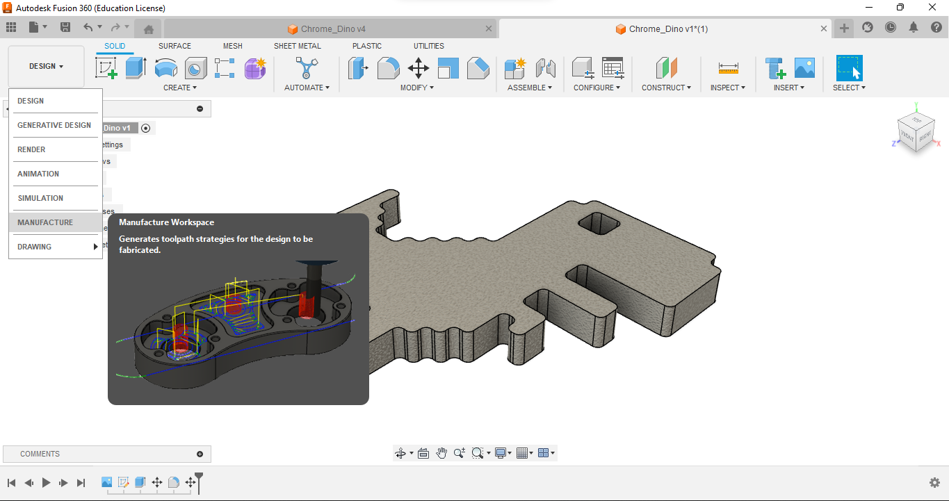
In this step, you move to the Manufacture workspace of Fusion 360 and then create a new setup, all values can be left as default. But be sure to adjust your orientations properly.
Firstly we create a 2D face operation with the half-inch flat end mill to create our starting surface by removing the excess stock material.
Secondly, we create a second operation using the 3D adaptive clearing operation to carve out the shape of the model with the quarter-inch flat-end mill tool. when setting up this operation be sure to use the stock bottom as the bottom height and an offset of -1mm should be allowed under the heights tab of editing the tool.
Thirdly, we then create a final operation using the 2D pocket operation and use the same quarter-inch face-end mill as before to drill out the space for the eye. when setting this up, use selection under geometry and choose only the bottom chain of the eye as the path and do the same actions under height as the previous step.
Finally, any other operation can be used to finish the surface and ensure that it is as smooth as possible.
Then you can export the G-code under post-process and pick your preferred settings as they fit your machine.
Sadly, I couldn't produce an actual model of this project as I have no access to a CNC machine but I hope you can.
Good luck!