Cheap CNC Probe
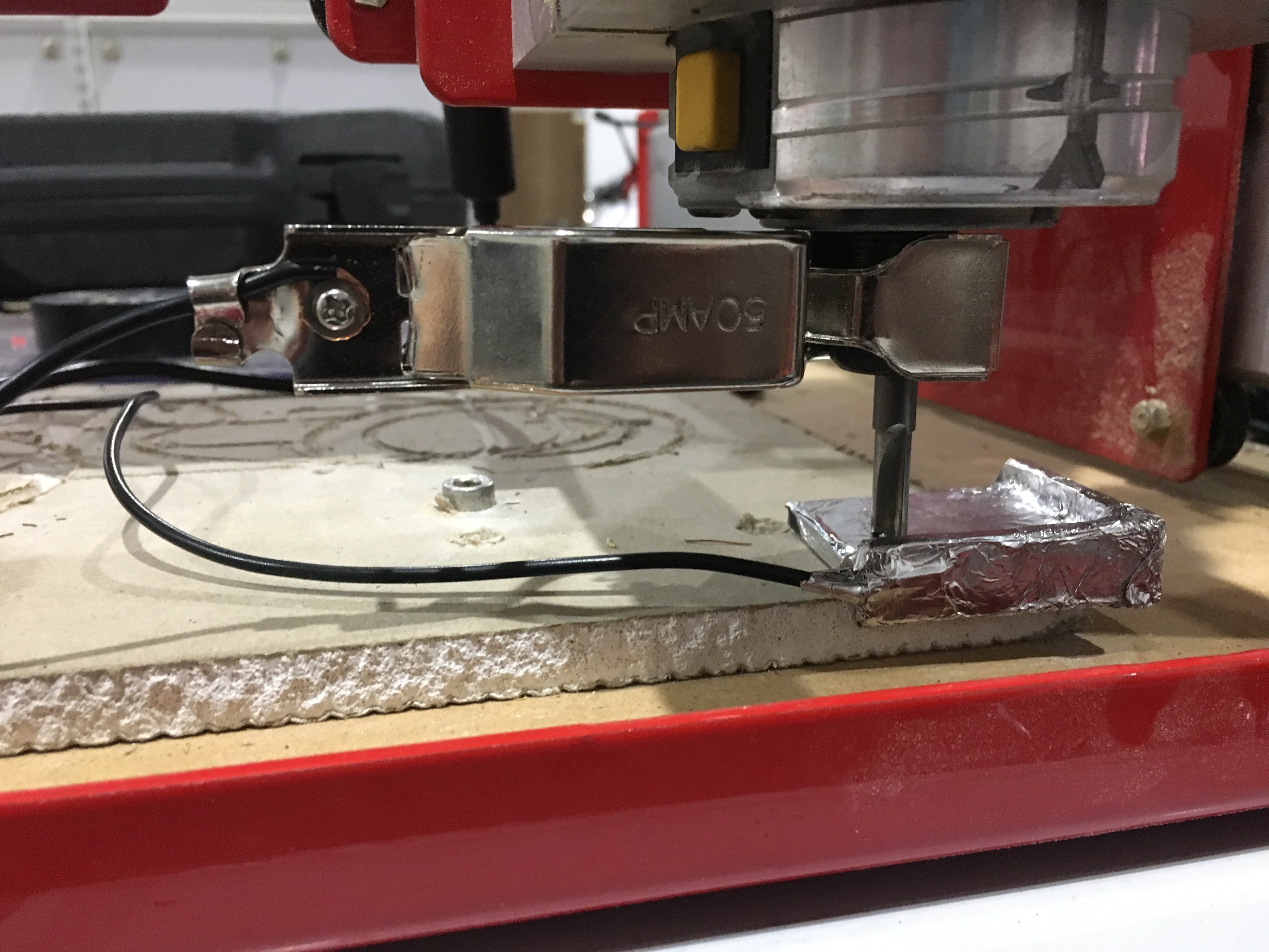
I’ve been using a CNC Router of a while now and I’ve been setting the X, Y and Z values by hand which can be annoying and inaccurate. To solve this, I decided to make my own CNC probe to make the process of setting the CNC values both faster and more accurate. I designed this probe in Fusion 360 which I then exported, and 3D printed.
What You Need:
Wire capable of carrying 12V
Aluminium Foil
1 Alligator Clip
3D Printer
Create a Sketch in Fusion 360
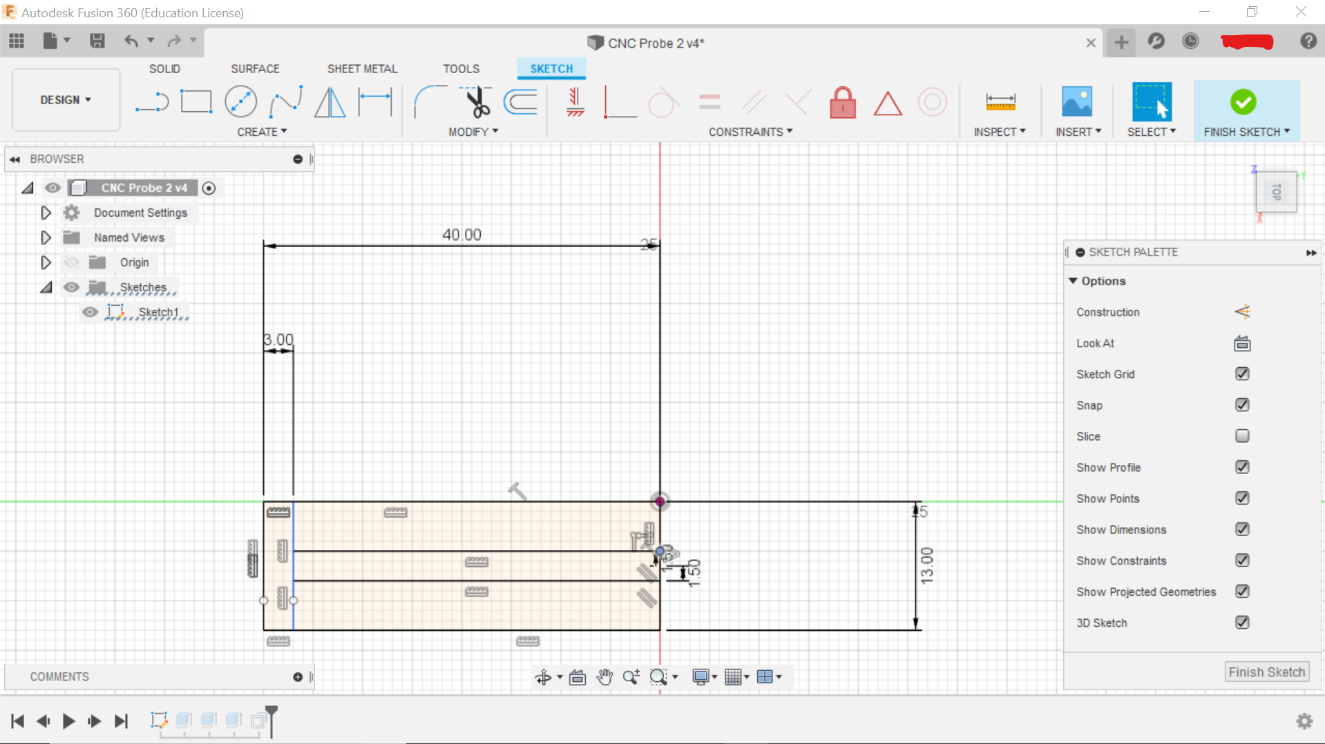
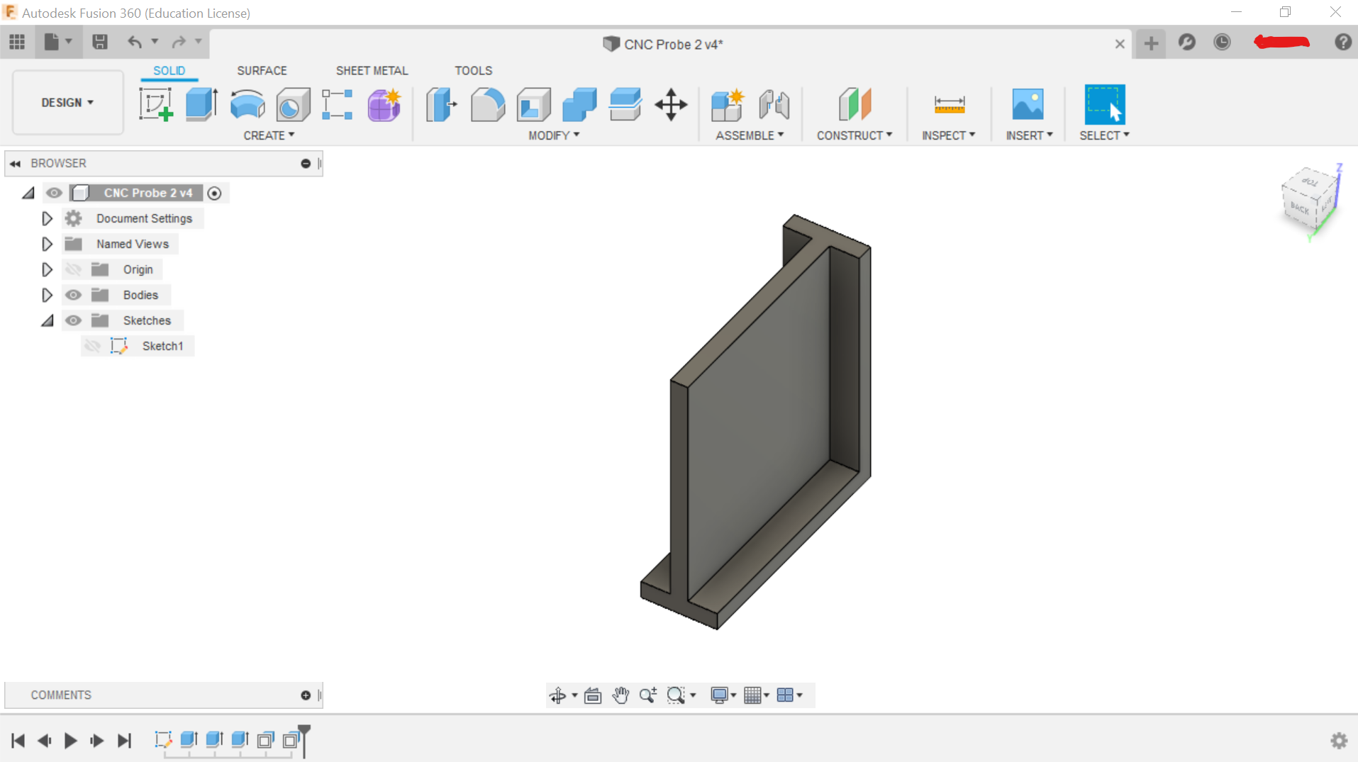
This was a very simple sketch that would have taken me 5 minutes to draw. Hopefully you can see the measurements in the picture above but if not, I will also put the STL and Fusion 360 file below. After I finished the sketch, I extruded it to 40mm (1.57 inch).
Exporting
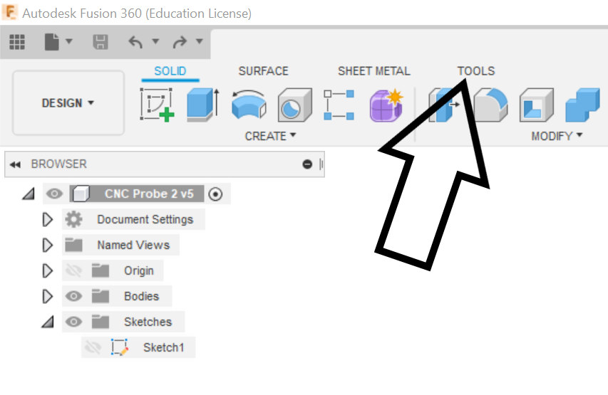
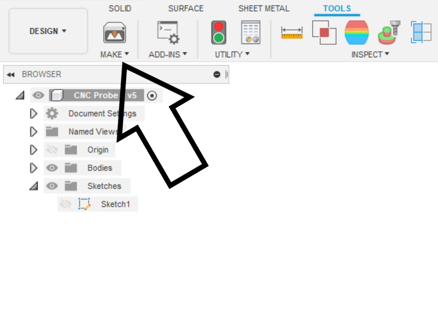
From the top menu you will see a tab called tools, click on it and the select on the first icon to the left. This will allow you to export your file to your slicer E.G Cura
Applying Aluminium Foil
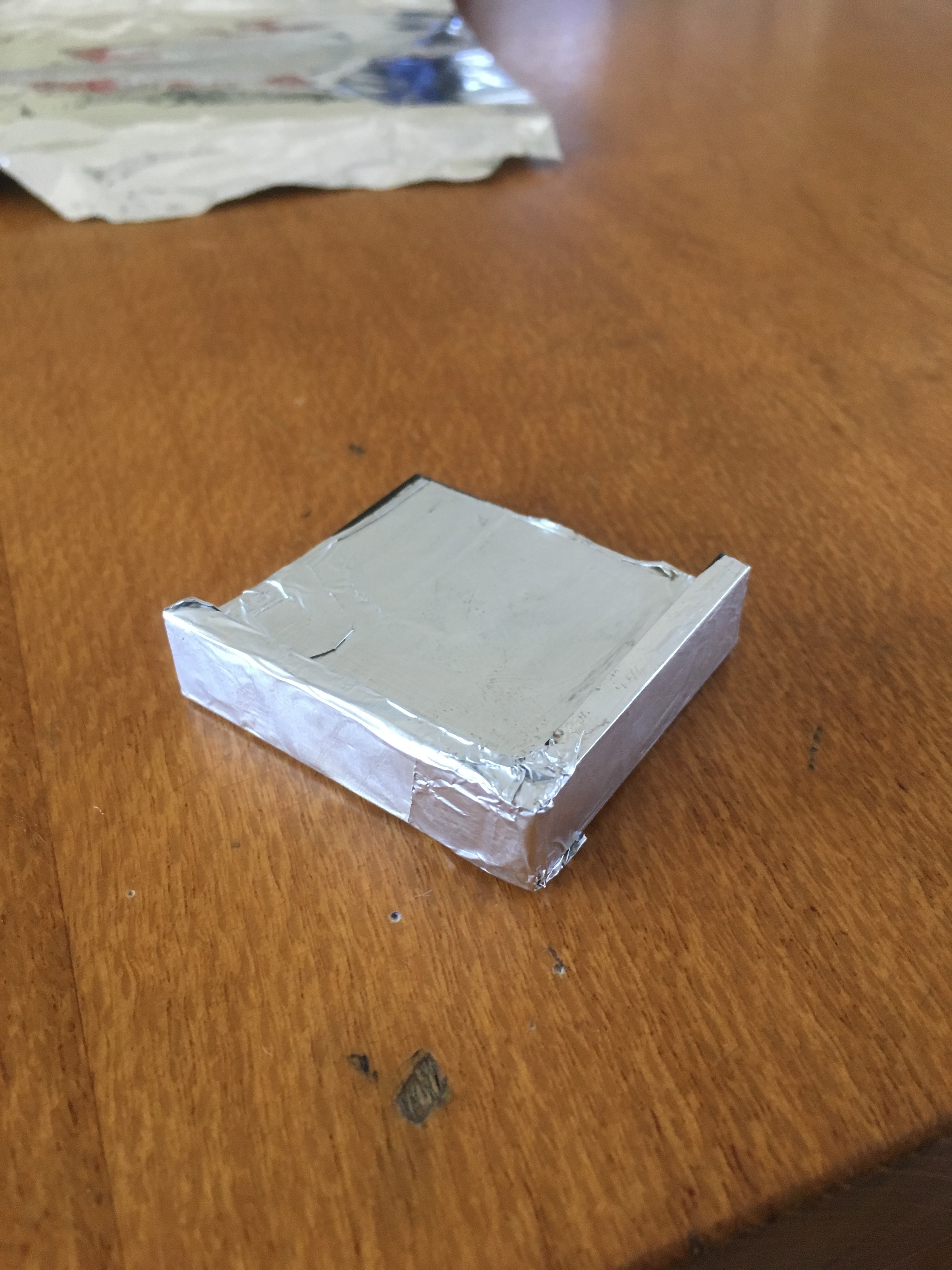
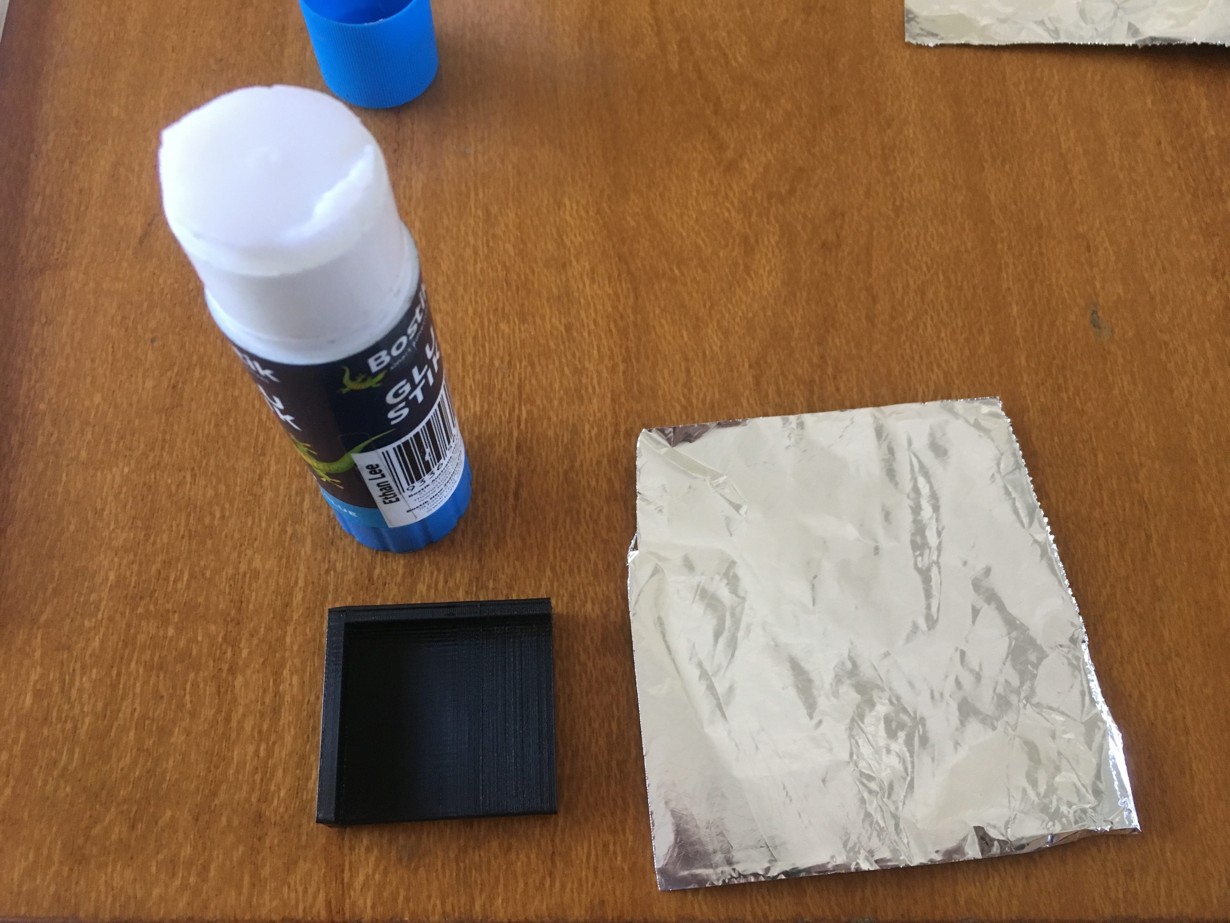
Once you have 3D printed the probe, the next step is to make it conductive so when the router bit hits the probe it will complete the circuit. I made mine by using some glue and a bit of aluminium foil. When I did this, I used 3 layers but if your alfoil it thick than you should be able to get away with one or two layers.
Making Sure Its Conductive
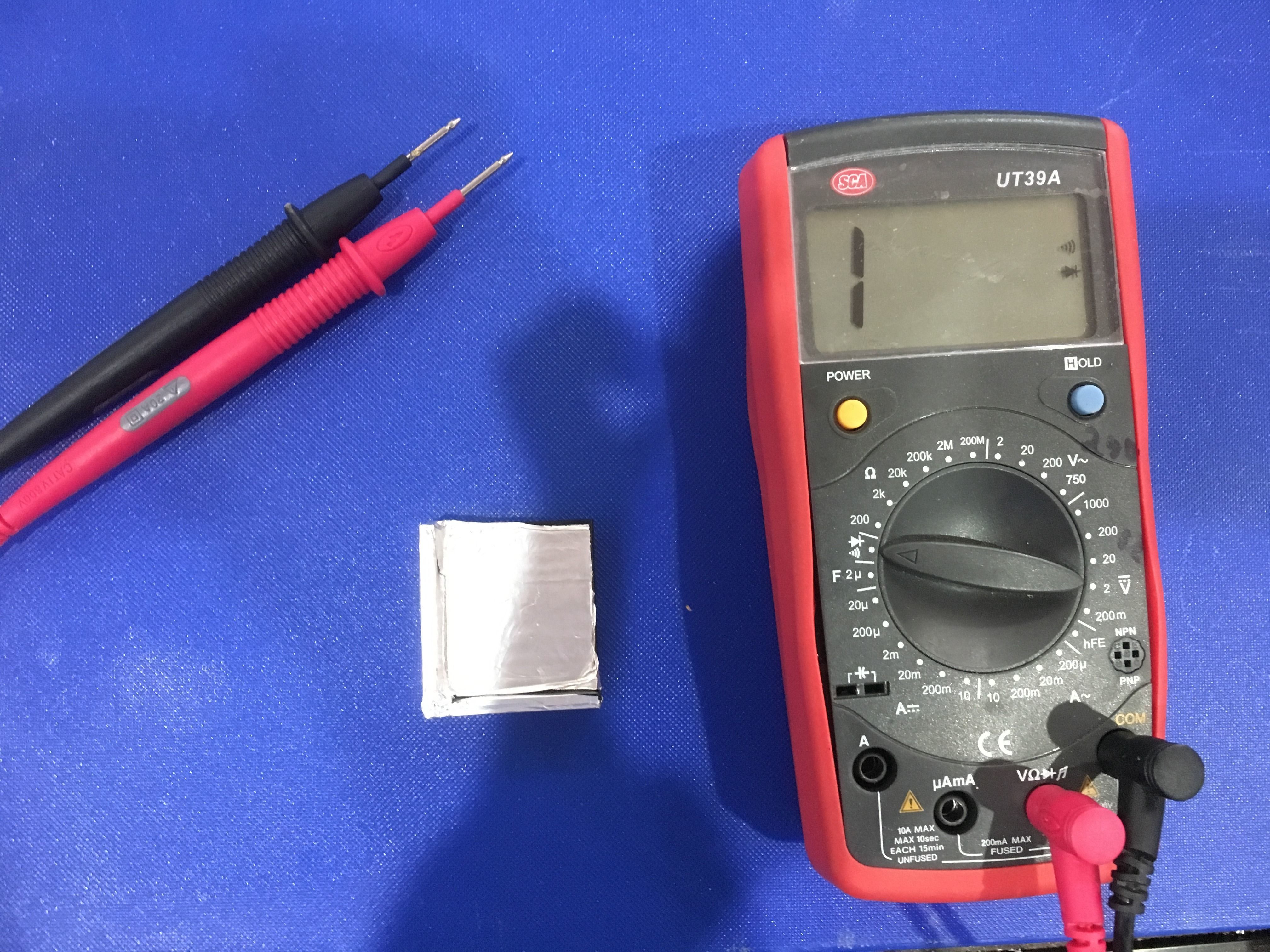
To do this I used some multimeters and set them to audible mode. This makes the multimeters beep every time there is a complete circuit. This is how we know if the probe is working. If you don’t hear a beep, I recommend redoing step 3.
Note: The three sides that the router bit touch MUST all conductive otherwise the probe won’t work
Adding the Wires
Once you’ve made sure your probe is conductive we have to add the wires. At this point I would have soldered the wires to the probe, but I don’t know how to solder so instead I glued the wires on with some model glue and put more foil over the top. We also need to add some wires to the alligator clips. It is also a good idea to check if the probe is still conductive at this point.
Adding the Connectors
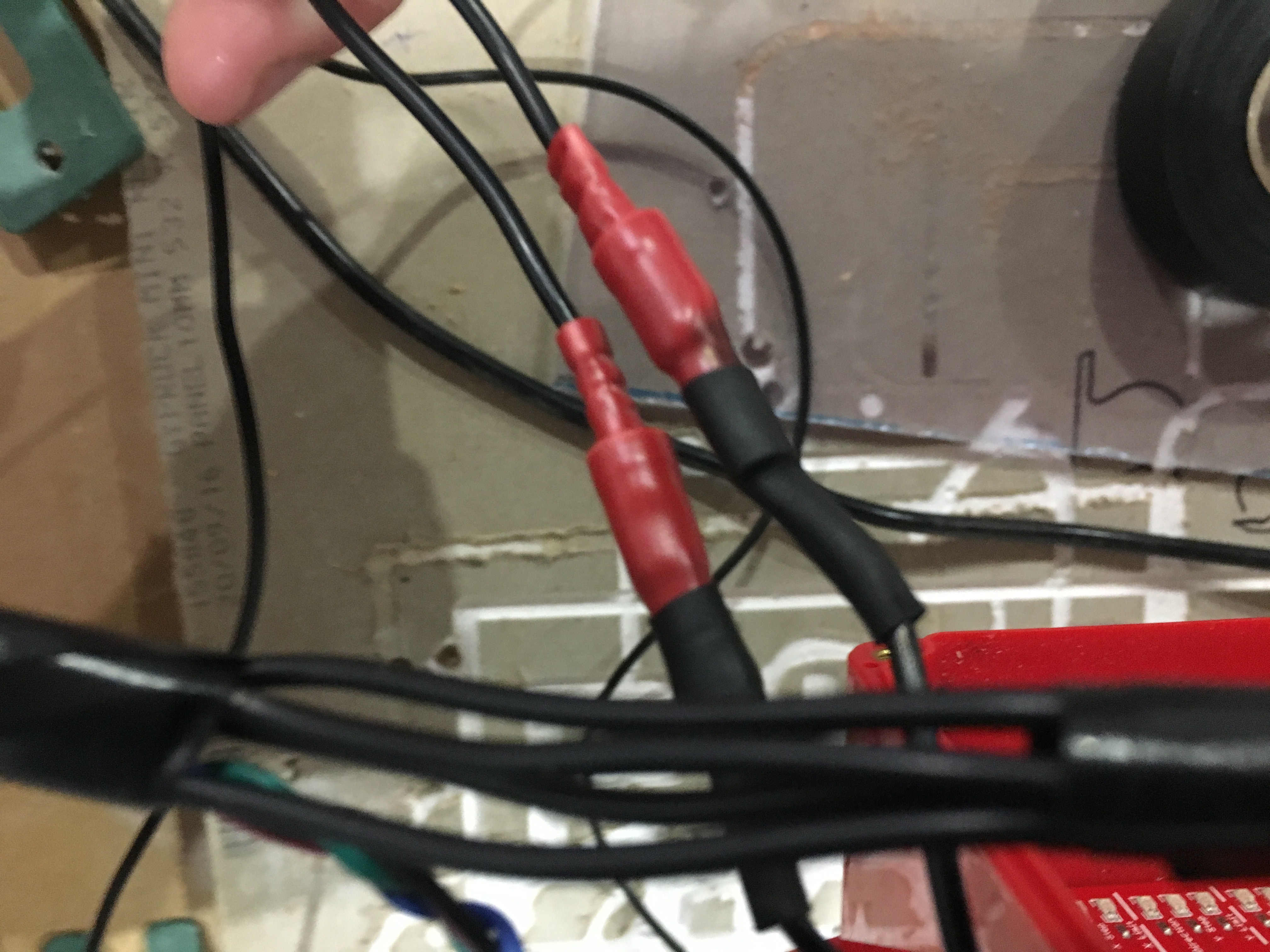
For this I used a bullet connector that I had lying around, however any other type of connector should work. You might be thinking why do we need the clips, well its so we can unclip the probe and move it out of the way when we need to.
Connecting to the Board
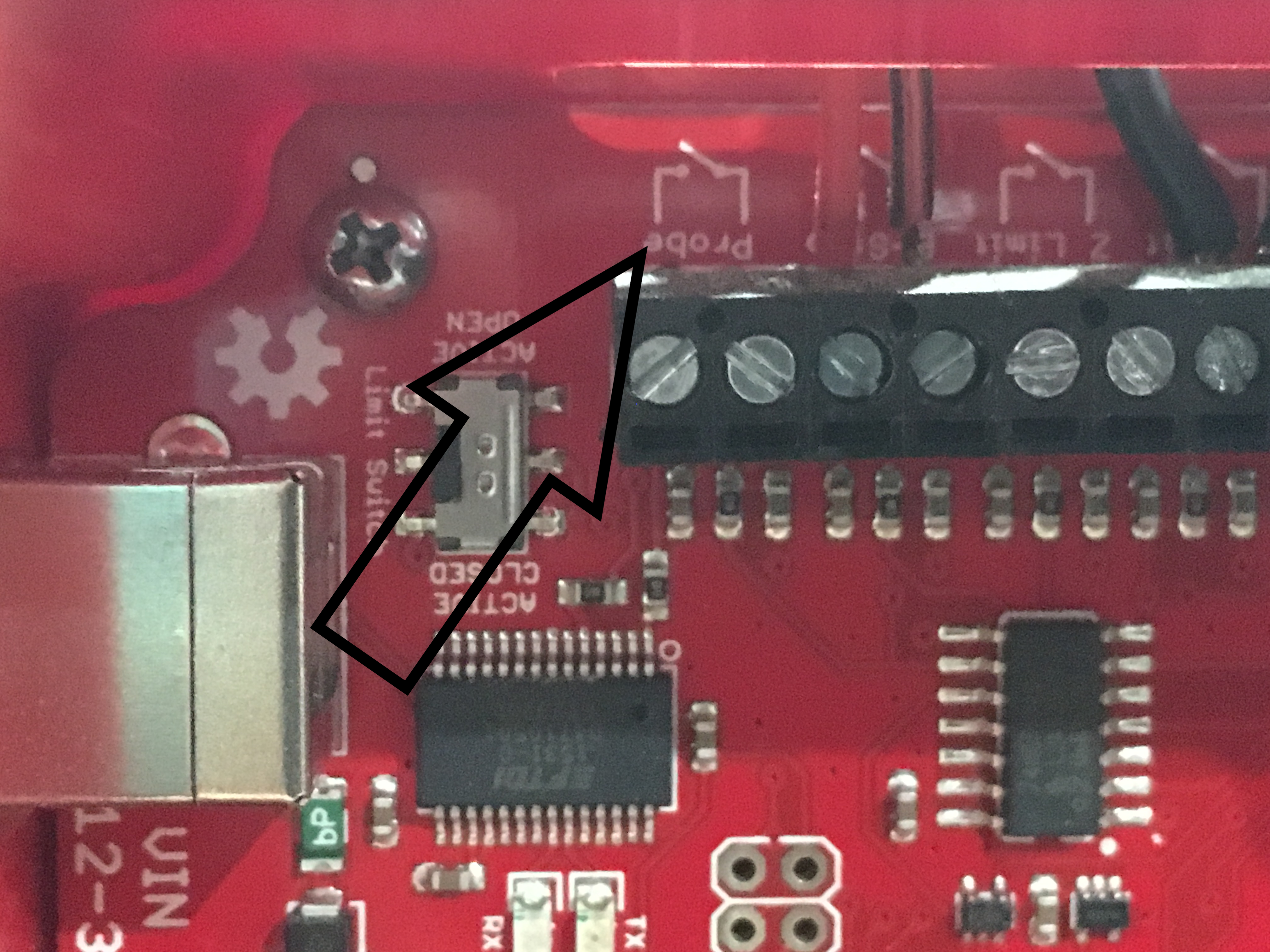
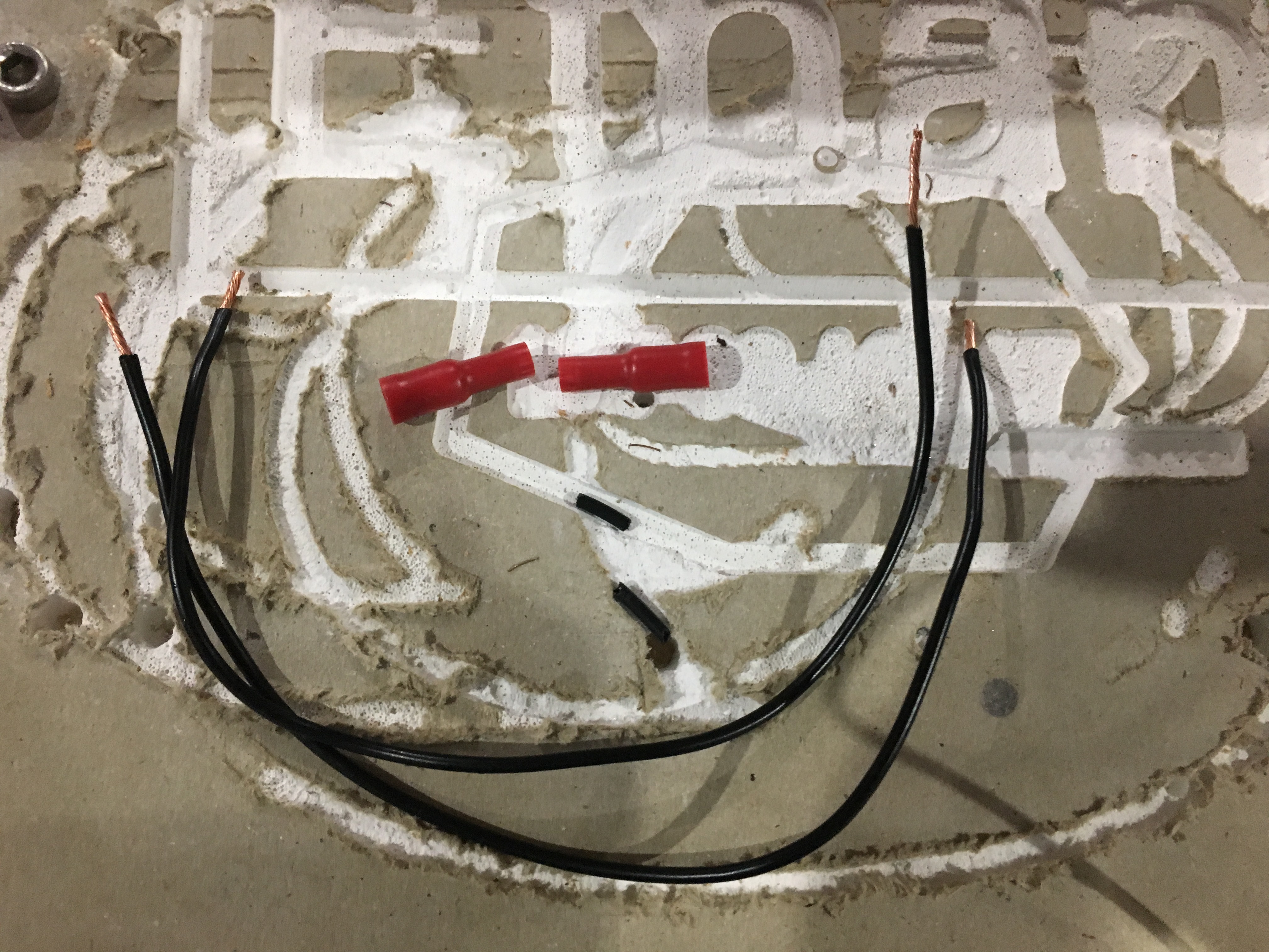
First you'll need to find the mother board on your CNC. Once you’ve found it you will need to find the sockets for a probe and connect the two wires. Then work out where you will keep the wires for the probe, you should make sure your wires are easy to access but not in the path of the CNC tracks. I decided to keep mine on the side of the mother board cover.
Software
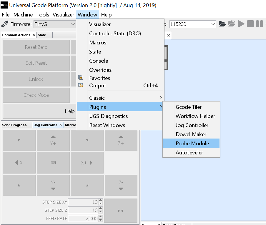
I use Universal G-Code sender to run my CNC. To use a probe in UGS you first need to select Probe Module. To do this go to Window, Plugins, Probe Module. Once you’re in the Probe Module tab you will need to set the size of the probe. Find where it says touch plate thickness and set it to the thickness of your probe.
Enjoy!

All done! Connect your CNC and enjoy your new probe. To start probing, jog your CNC over the probe and click the measure outside corner button and watch the CNC do its thing. Make sure that your touch probe is connected though otherwise it won’t work!