Charlieplexed Row of LED Lights, for the Arduino
by computergeek in Circuits > Arduino
53266 Views, 134 Favorites, 0 Comments
Charlieplexed Row of LED Lights, for the Arduino
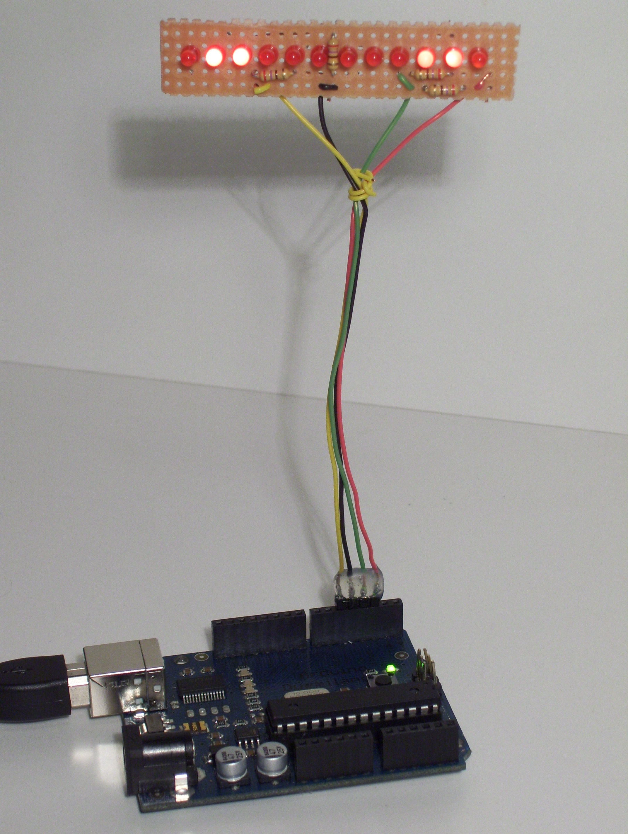
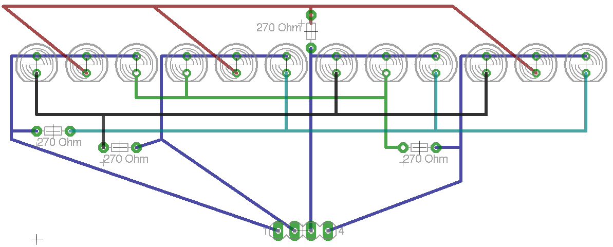
This is my instructable on charlieplexing a LED row/string with the arduino. I noticed that there weren't many instructables on charlieplexing using an arduino, so i made this. I tried to keep the project simple, but that didn't work very well. The soldering is complex, I wouldn't recommend this as a first time soldering project.
Here's some background on charlieplexing: en.wikipedia.org/wiki/Charlieplexing
I took about 80 pictures & not all of them made it into the main steps, but you can find them in step 9: Extra Pictures
If you have any comments, questions &/or suggestions please ask them!
Here's some background on charlieplexing: en.wikipedia.org/wiki/Charlieplexing
I took about 80 pictures & not all of them made it into the main steps, but you can find them in step 9: Extra Pictures
If you have any comments, questions &/or suggestions please ask them!
Parts List:
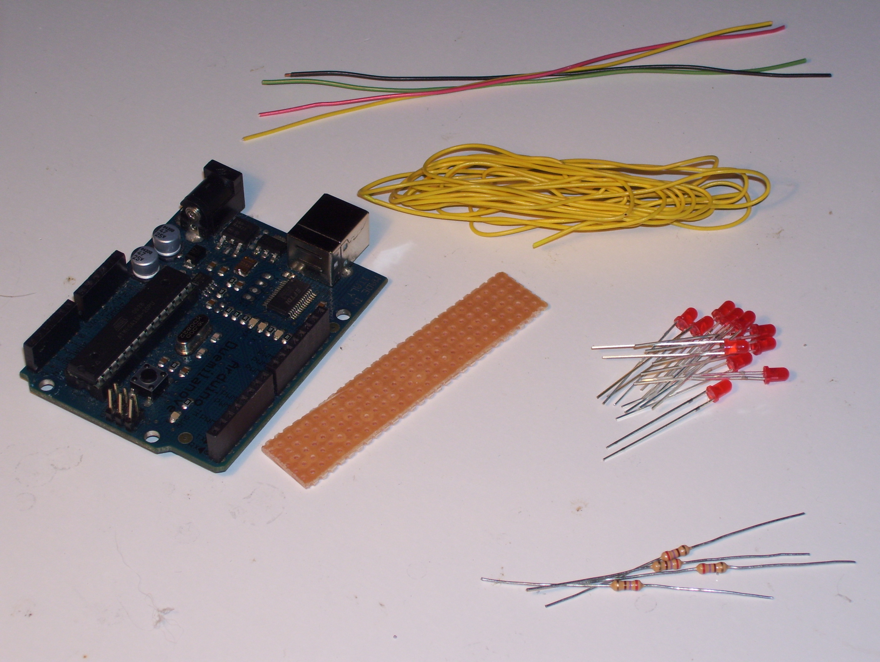
Parts:
- 12 LED's; I'm using some 3 mm Red LED's
- 4, 270 Ohm resistors; You can use other values as well
- Perfboard/Veroboard; I used a piece 27 holes x 5 holes
- Wire; I used some 26 gauge, solid core wire
- Header pins (optional)
- Arduino
Tools:
- Soldering Iron
- Hot glue gun (optional)
- Helping hand (optional)
Solder the Anodes of the LED's
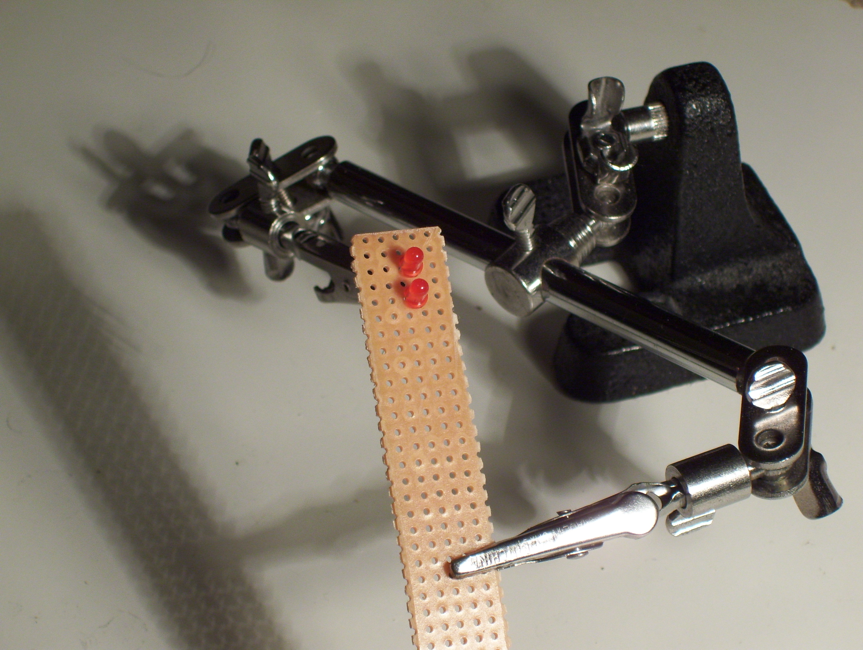
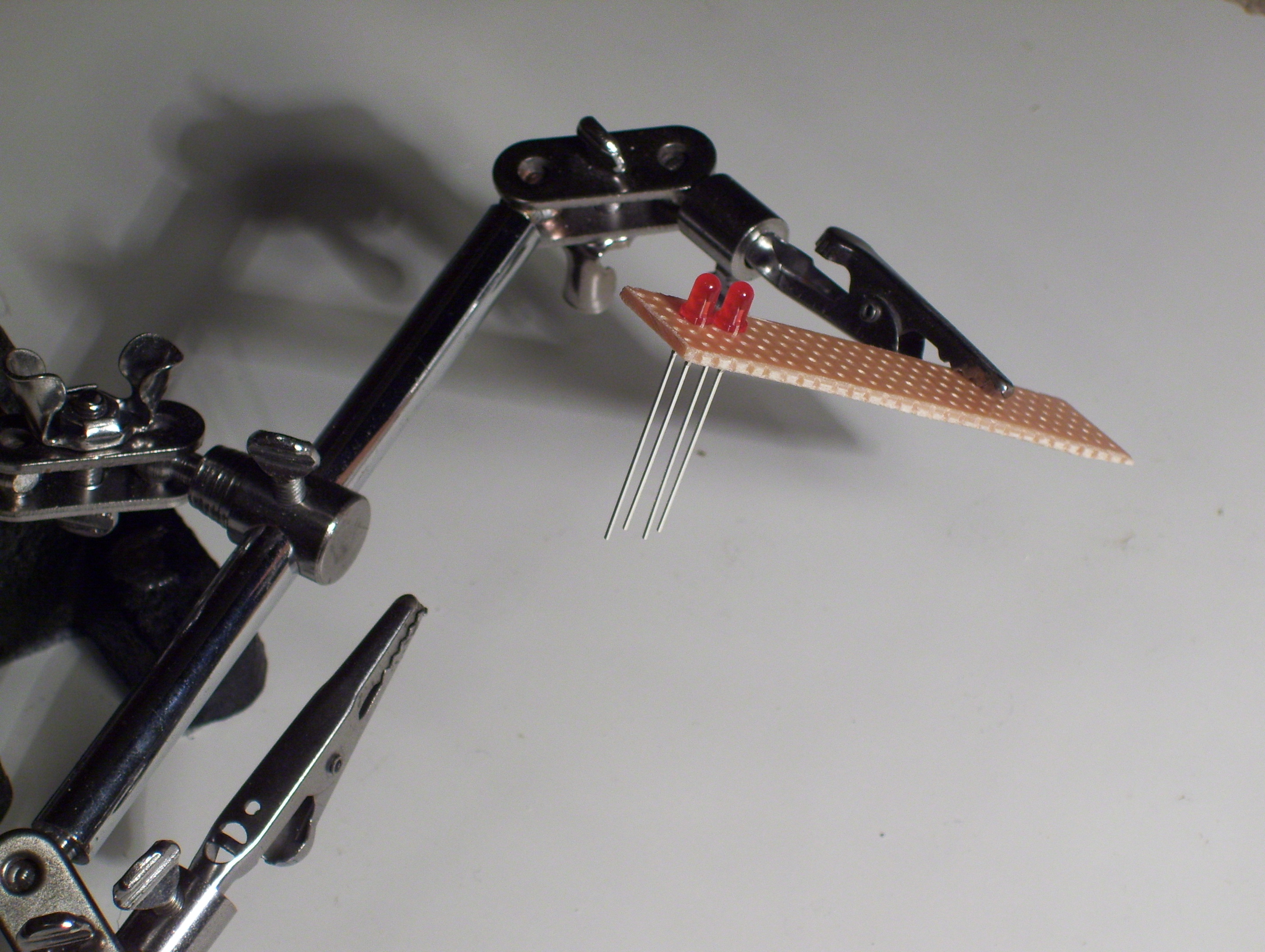
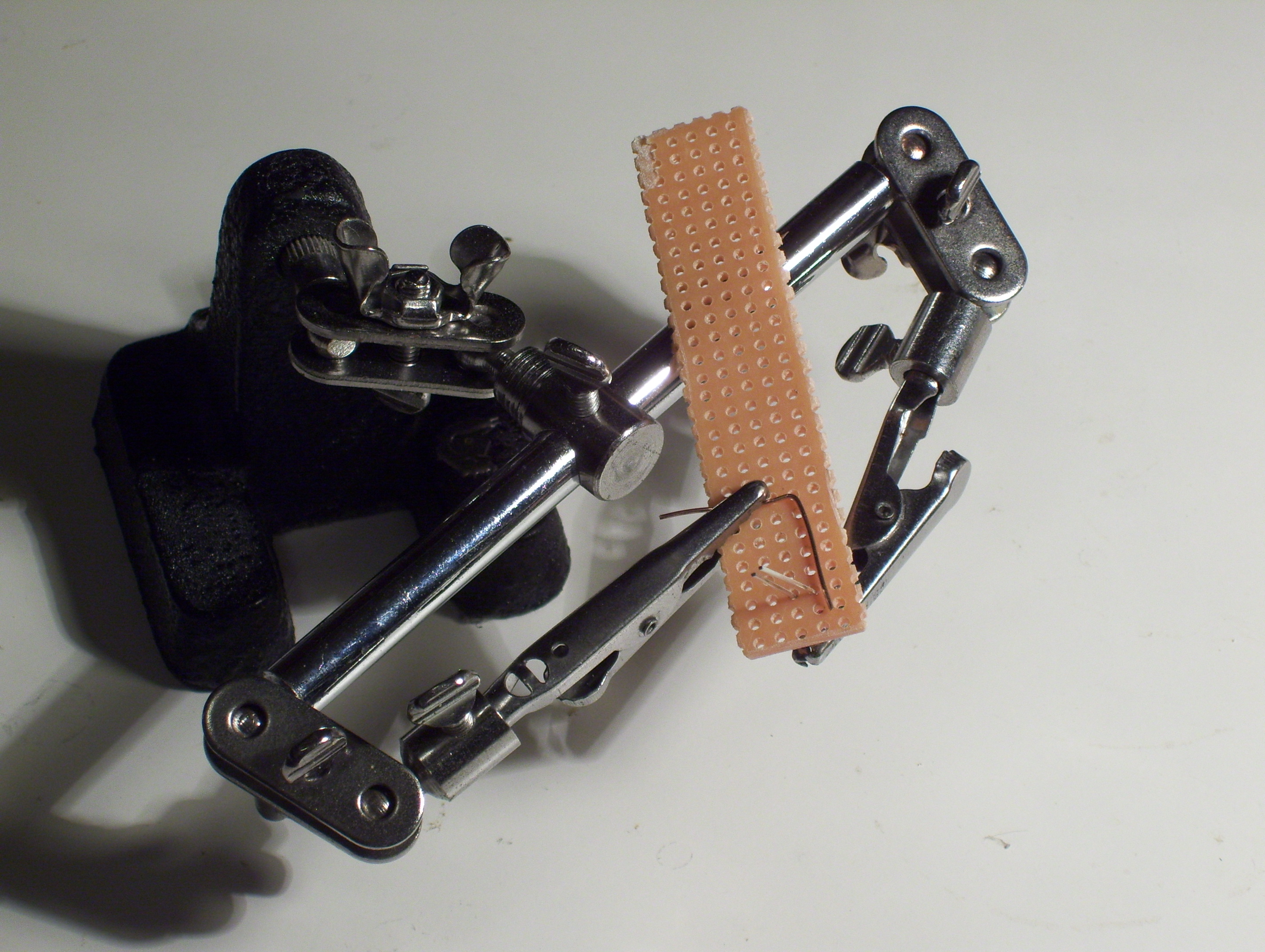
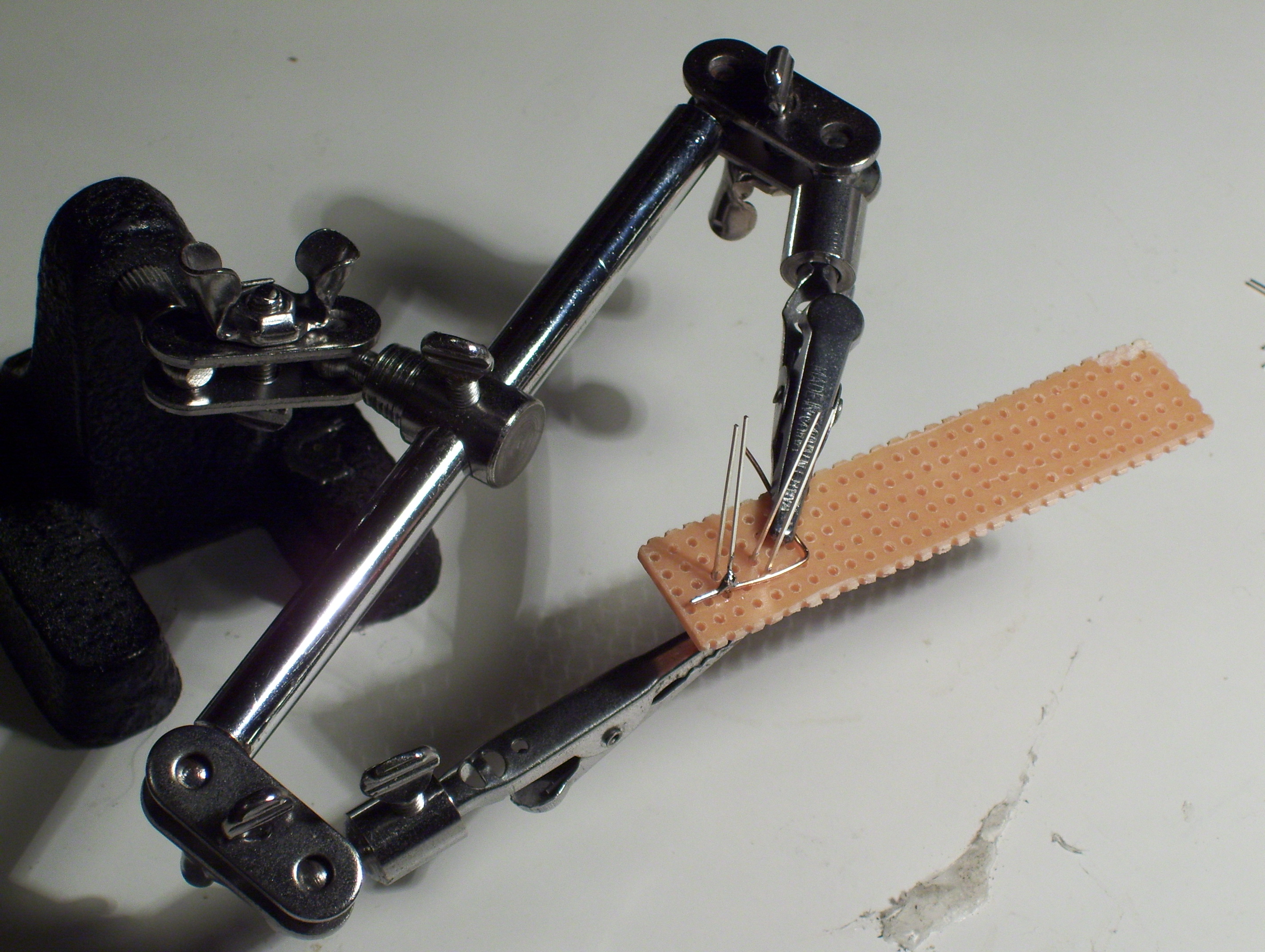
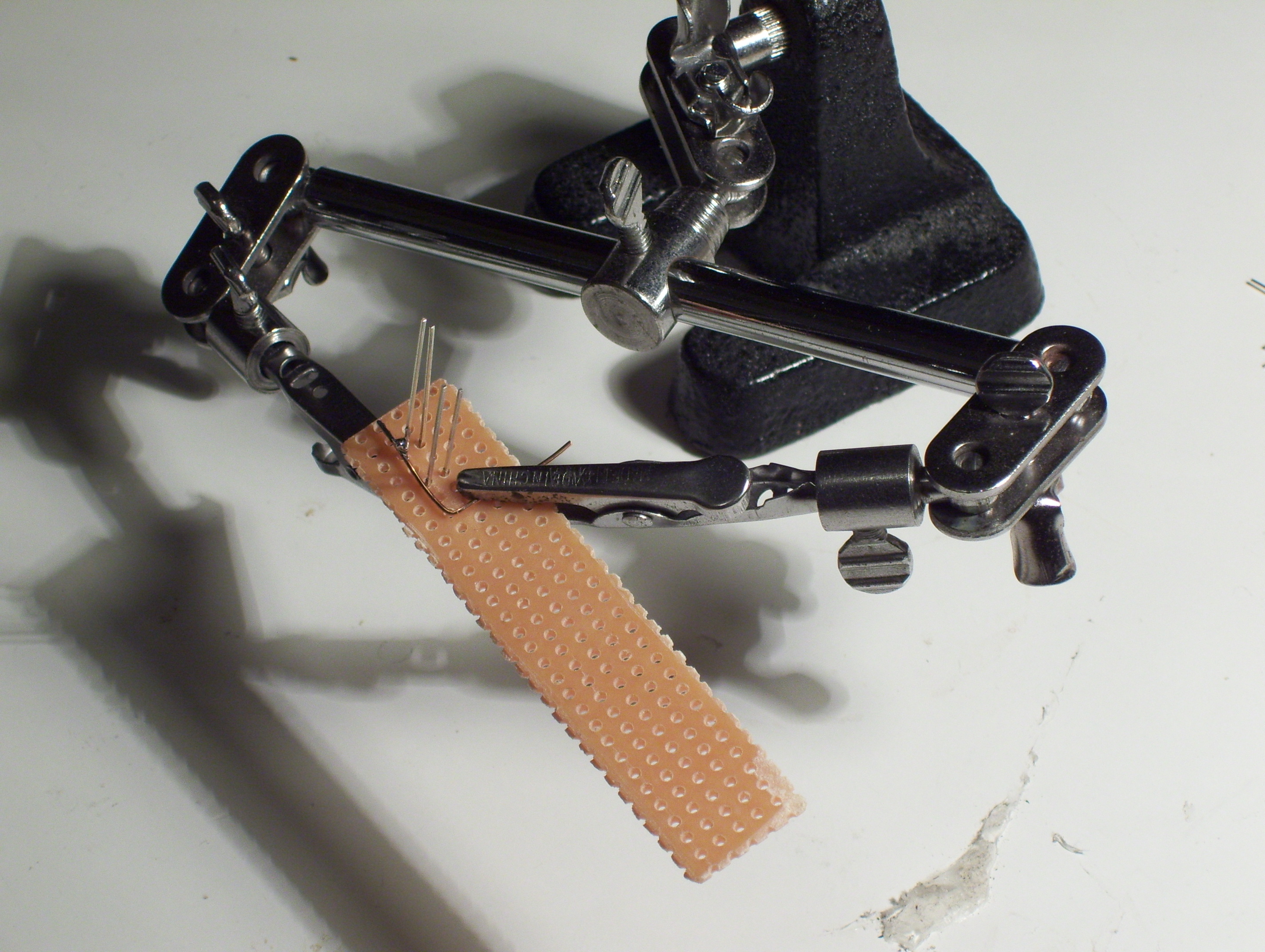
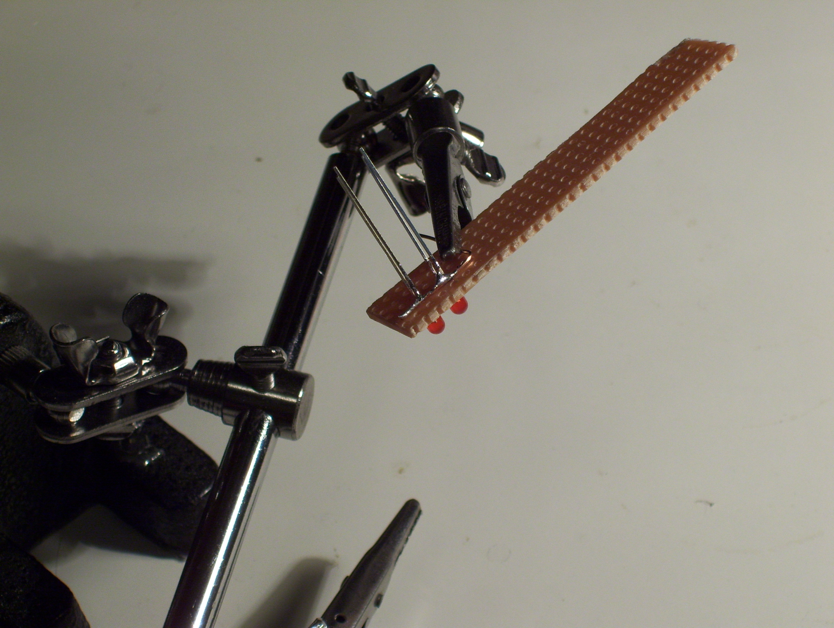
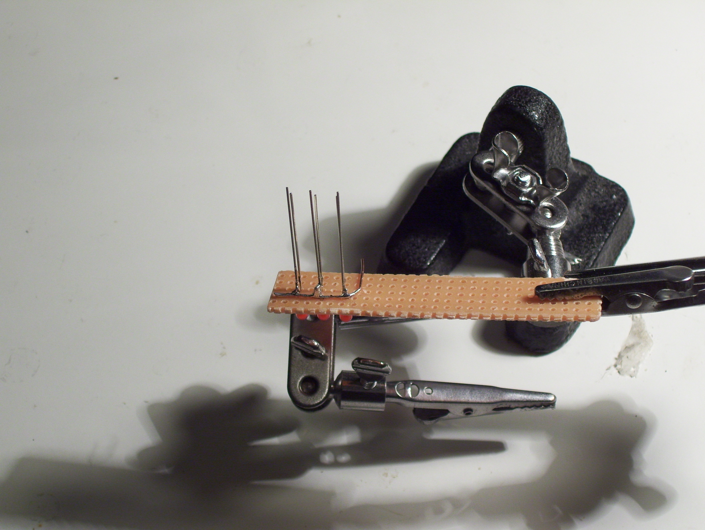
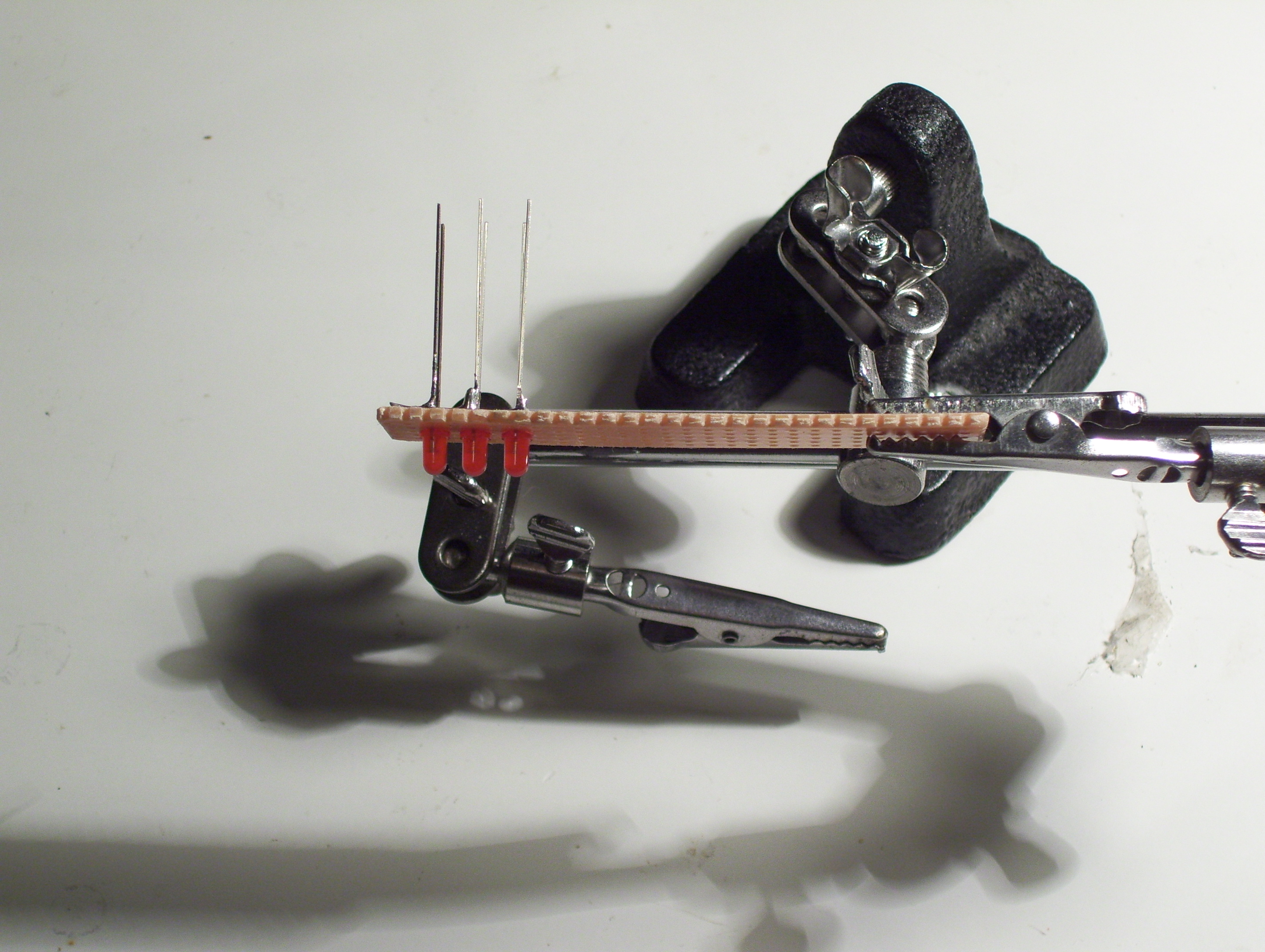
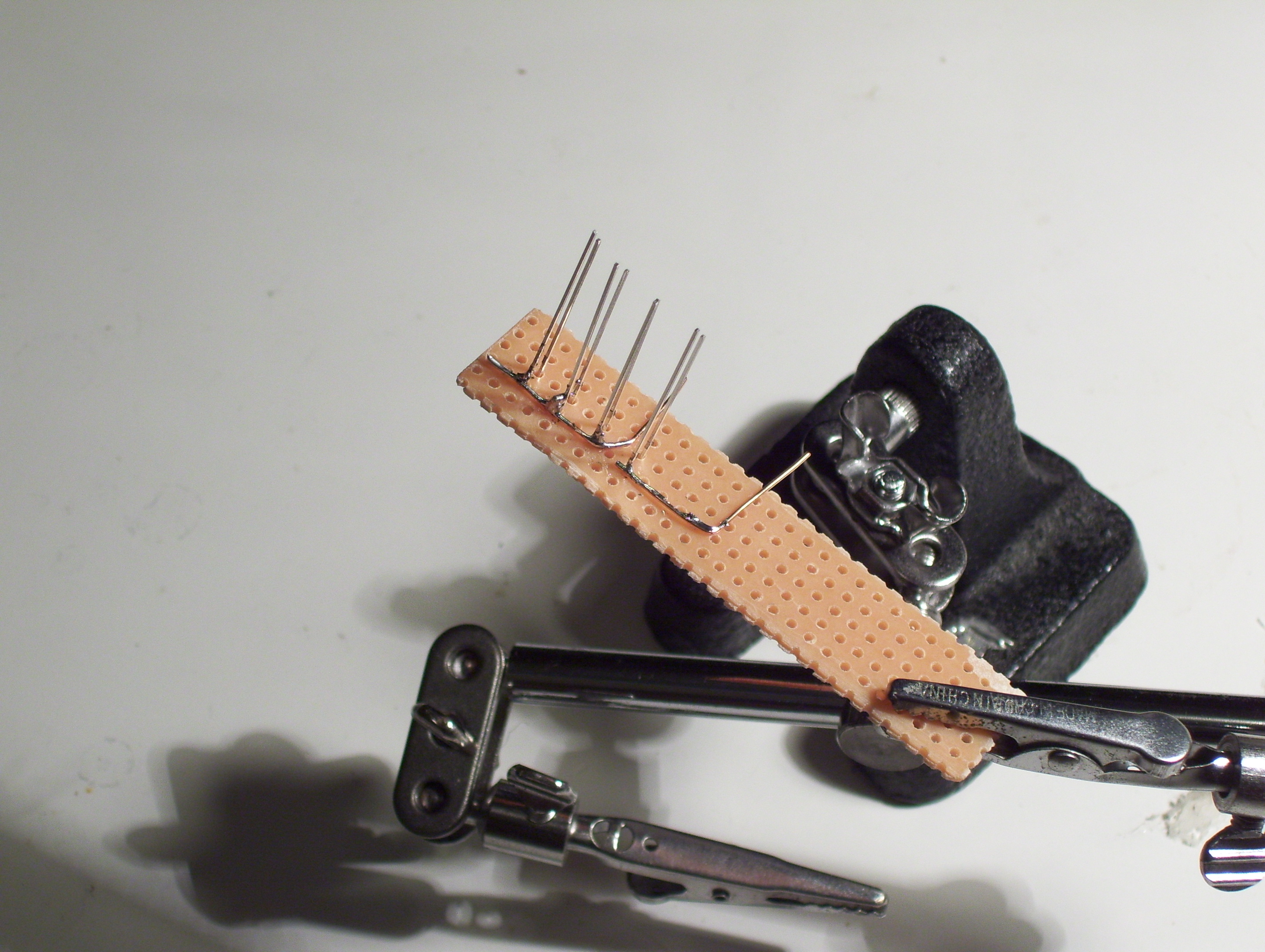
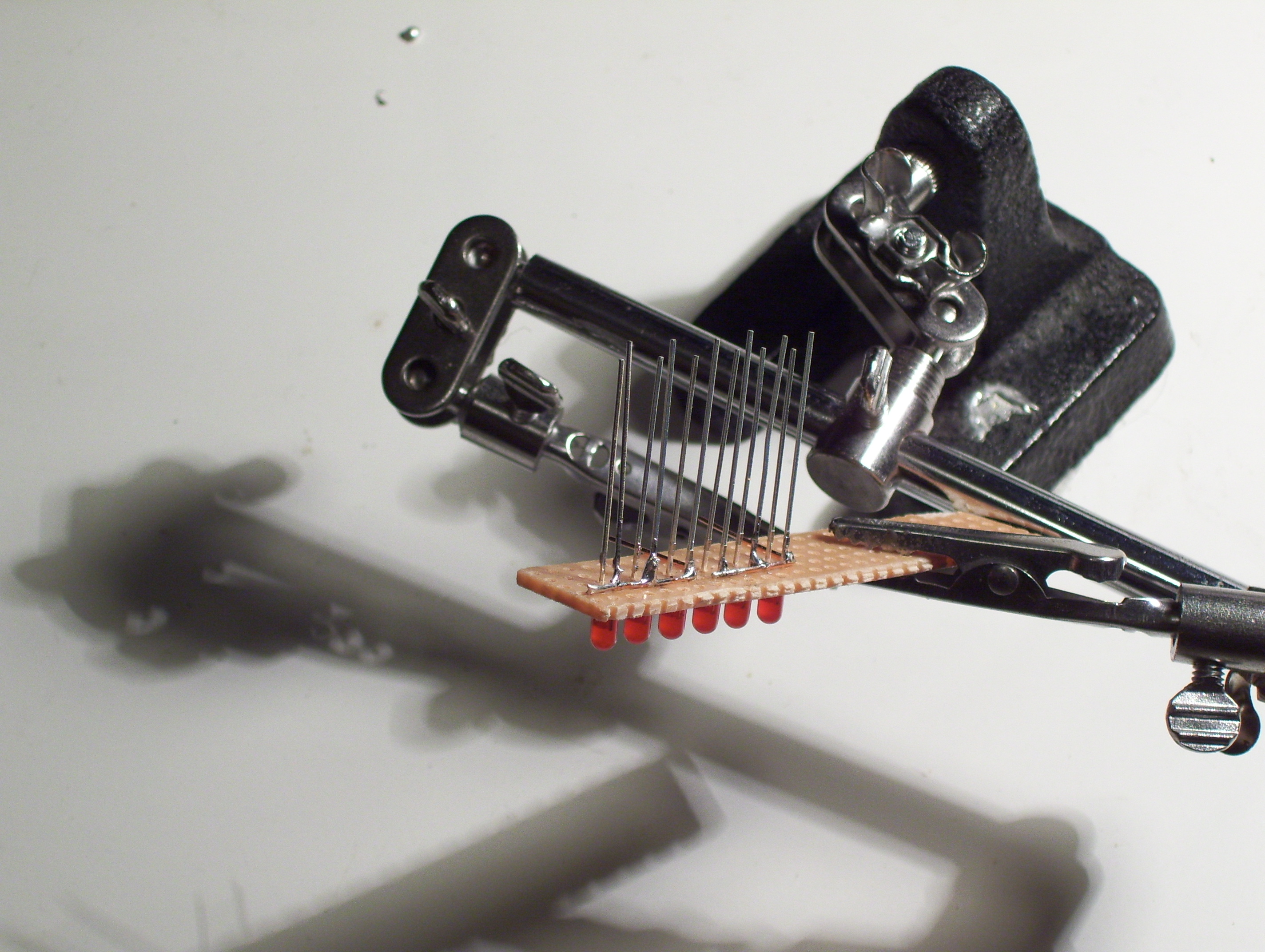
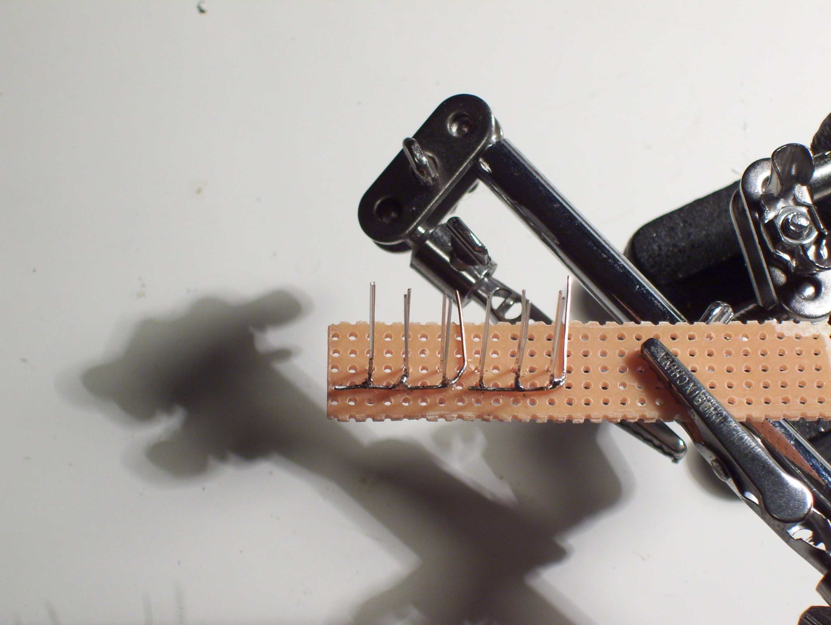
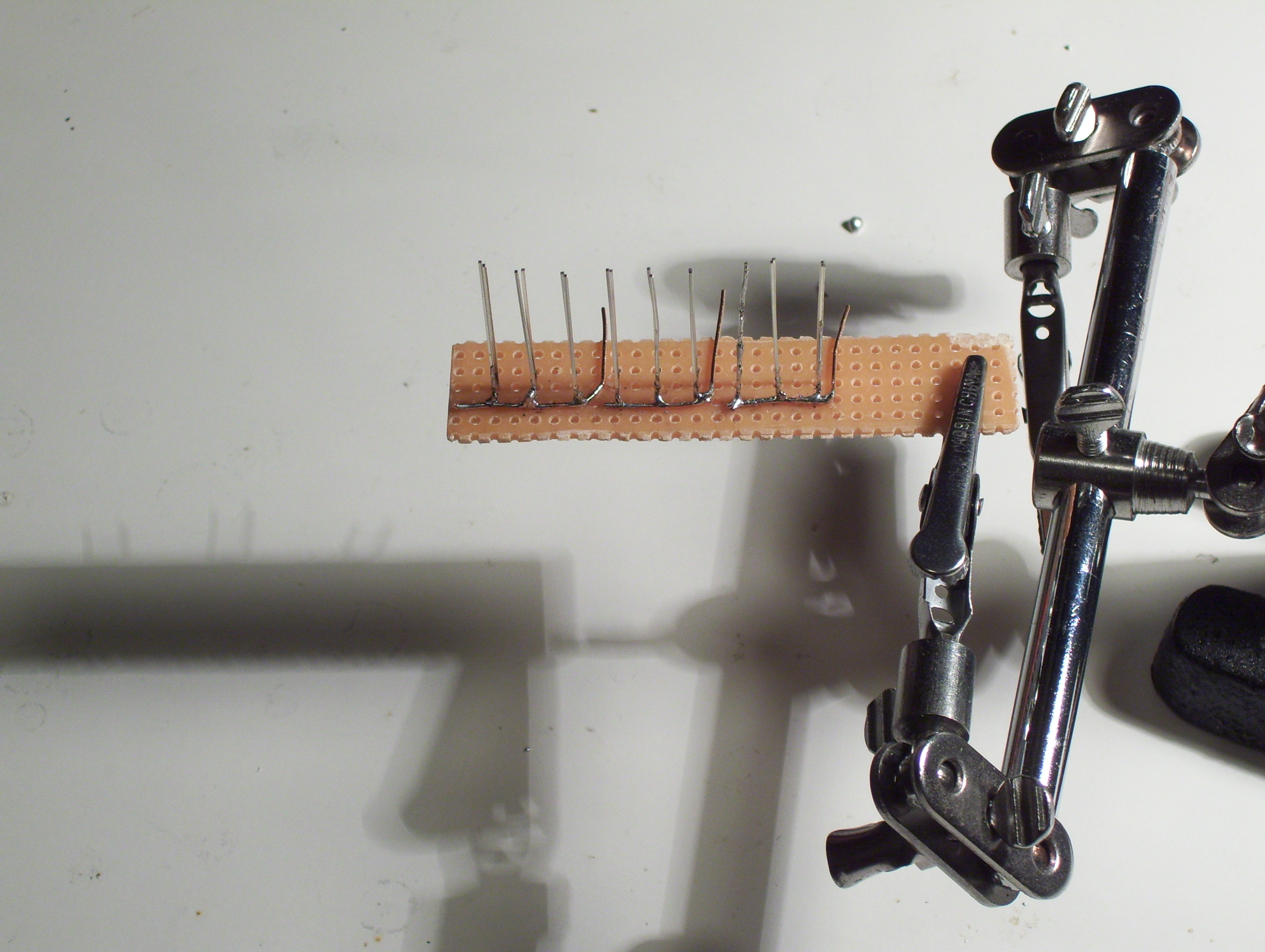
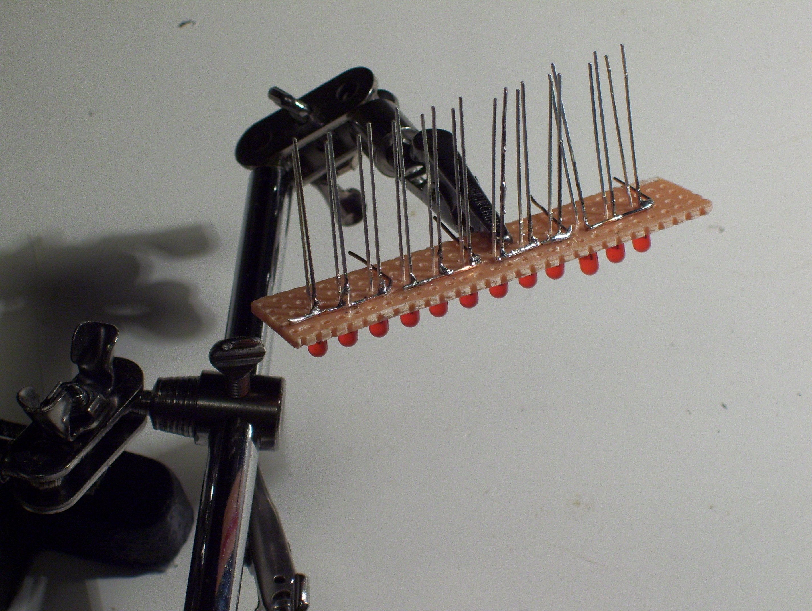
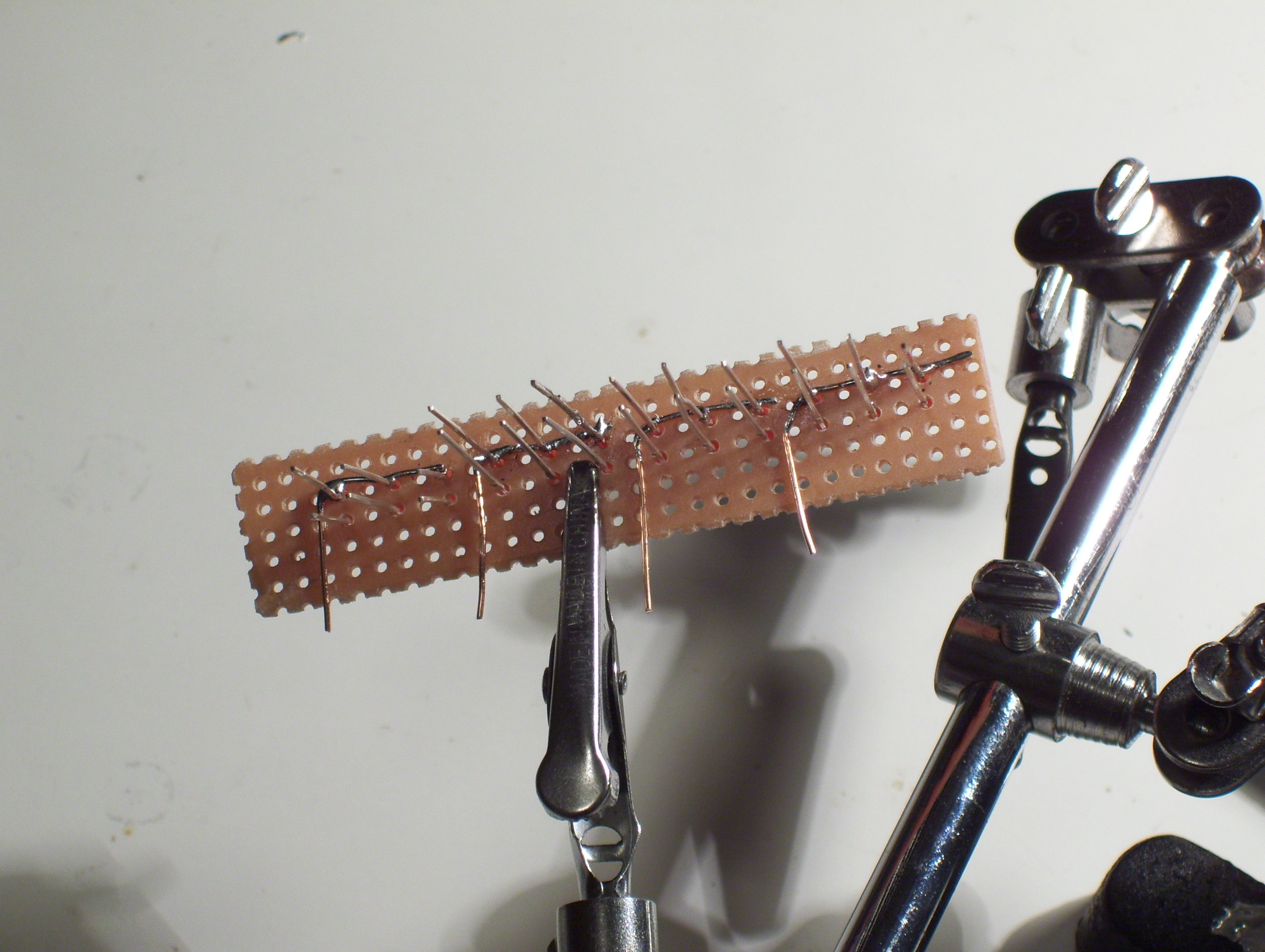
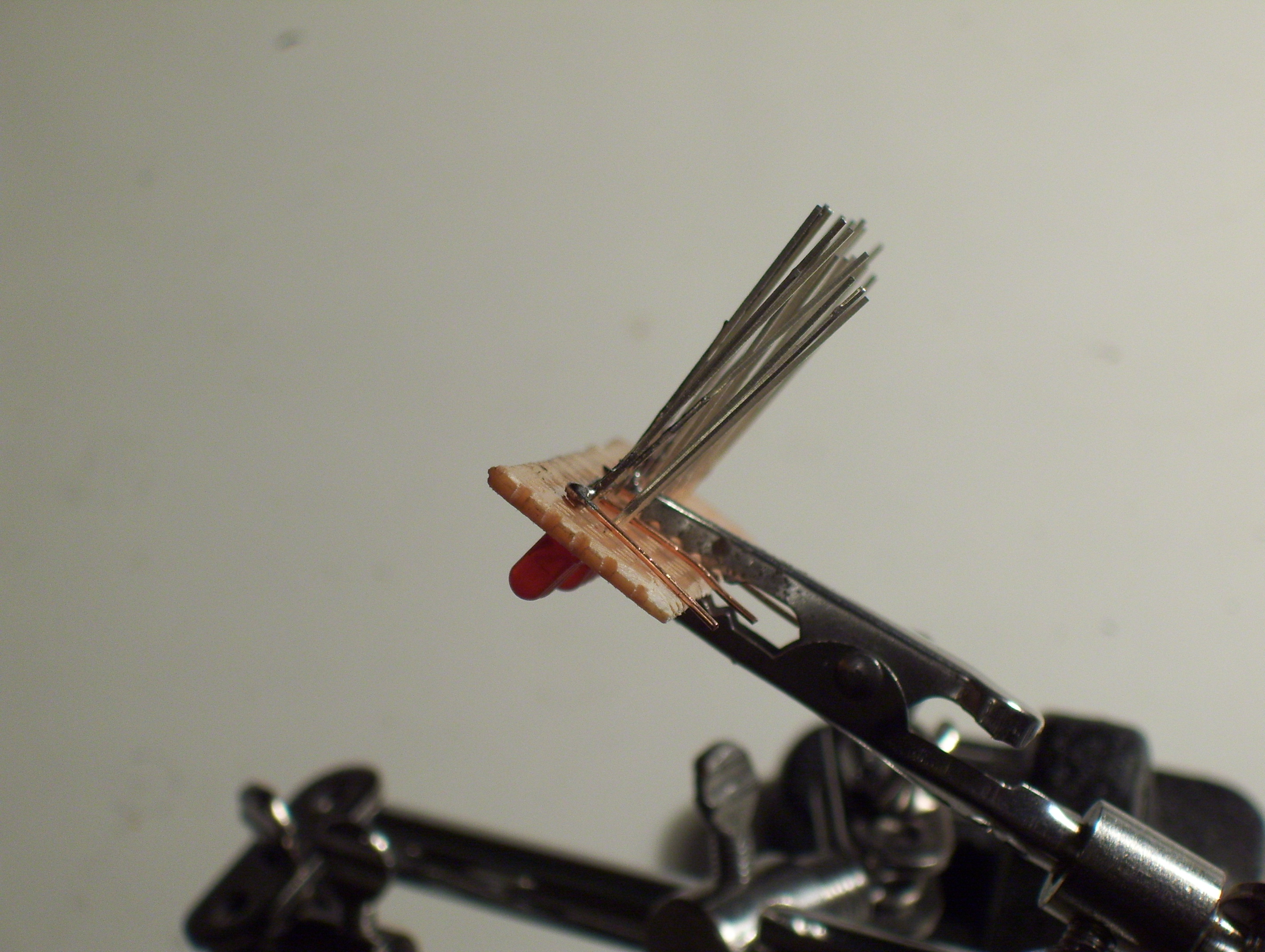
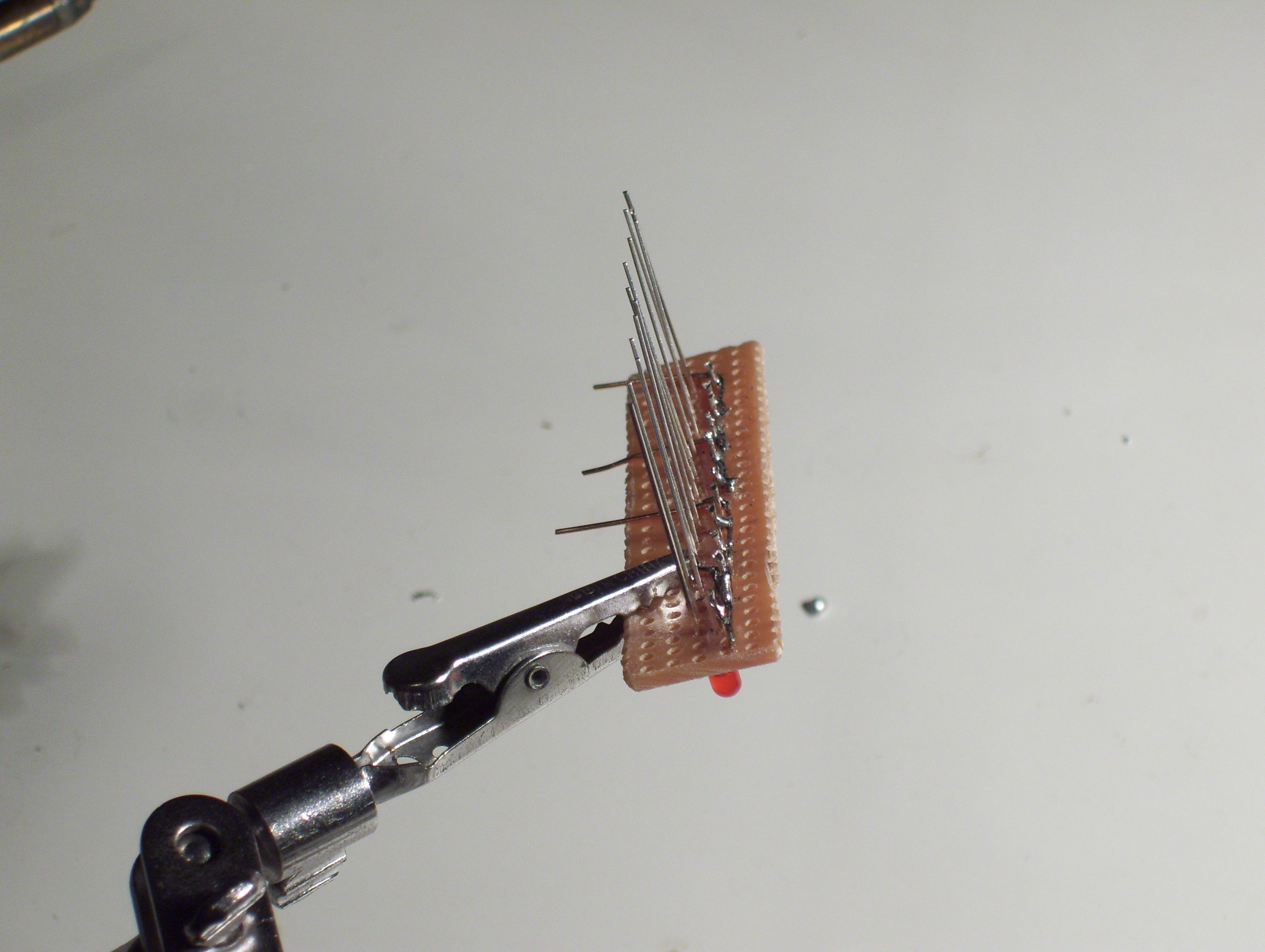
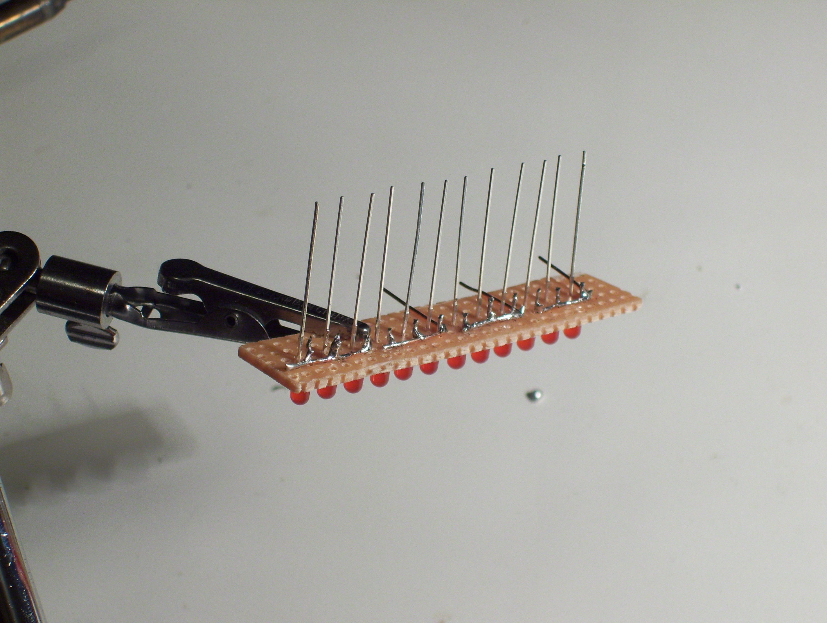
There's not much to say about the next few steps, but there's a few main points I'll mention.
- The LED's anodes are soldered in groups of 3
- Make sure the 4 groups don't get joined together, but stay separate
The wires that connect the 4 groups are kind of shaped like a L.
- The LED's anodes are soldered in groups of 3
- Make sure the 4 groups don't get joined together, but stay separate
The wires that connect the 4 groups are kind of shaped like a L.
Bend the Cathodes
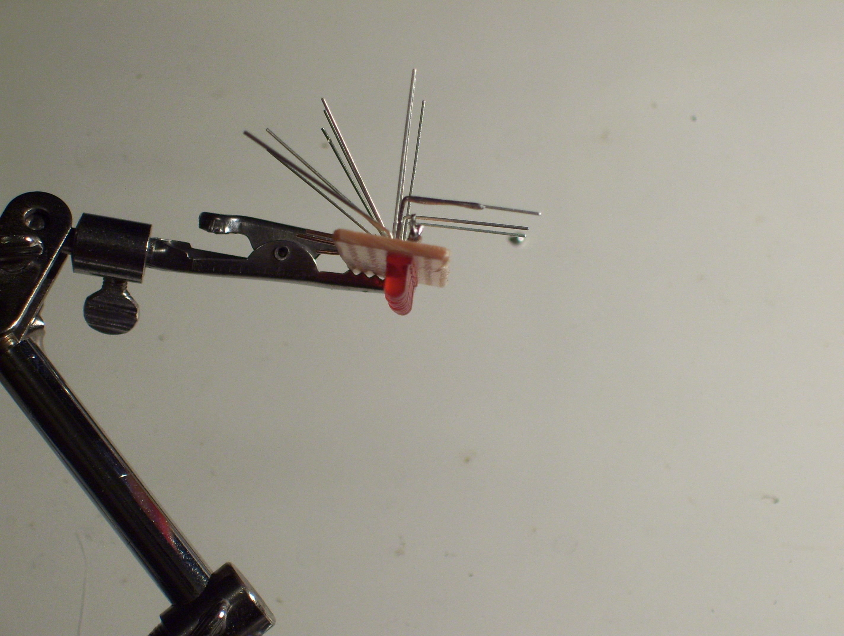
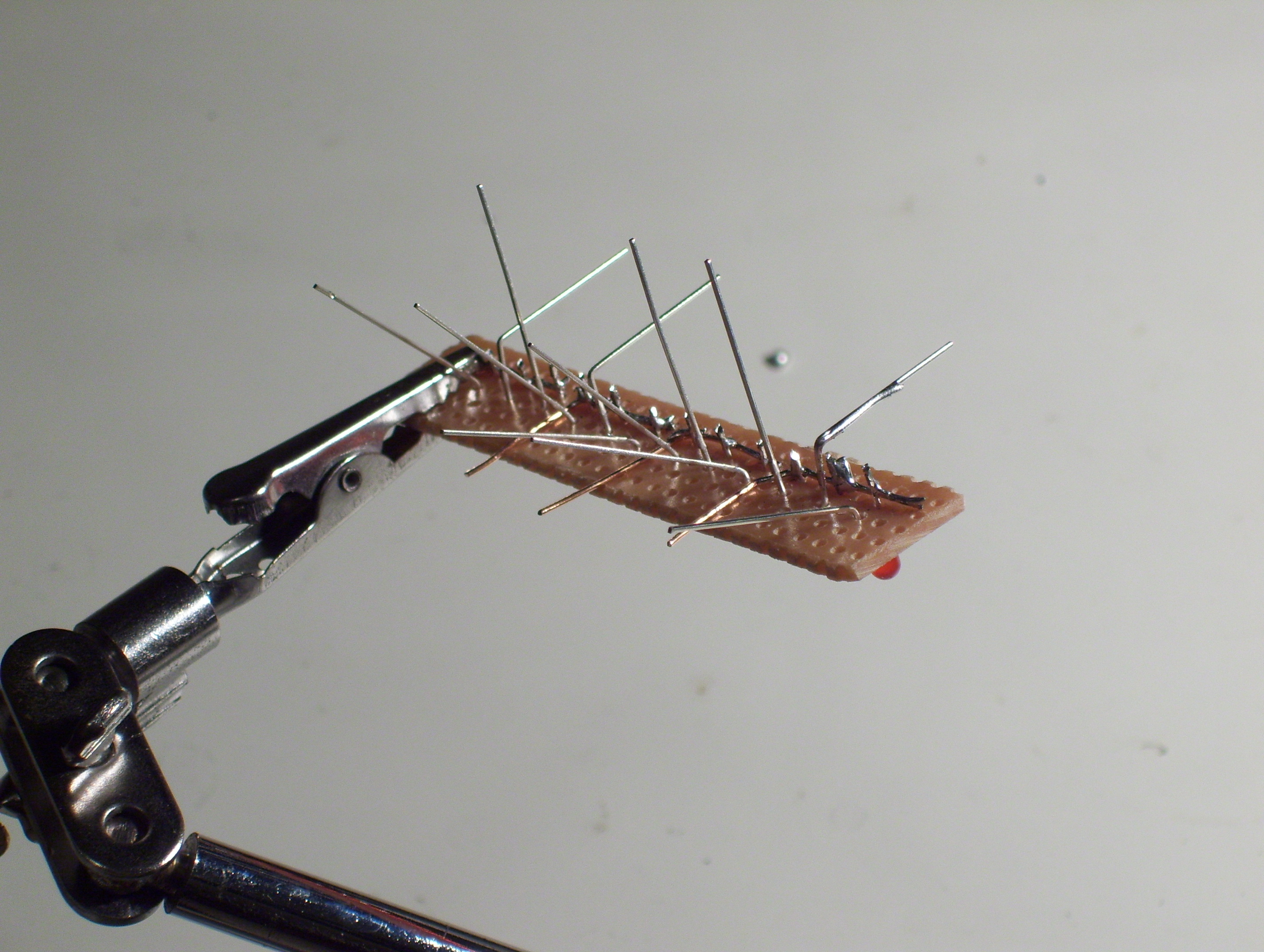
Main Points:
- You should end up with 4 different rows
- Make sure each of the the 4 rows contain only 3 connections to the cathodes & only one from each group of LED
- You should end up with 4 different rows
- Make sure each of the the 4 rows contain only 3 connections to the cathodes & only one from each group of LED
Solder the Cathodes
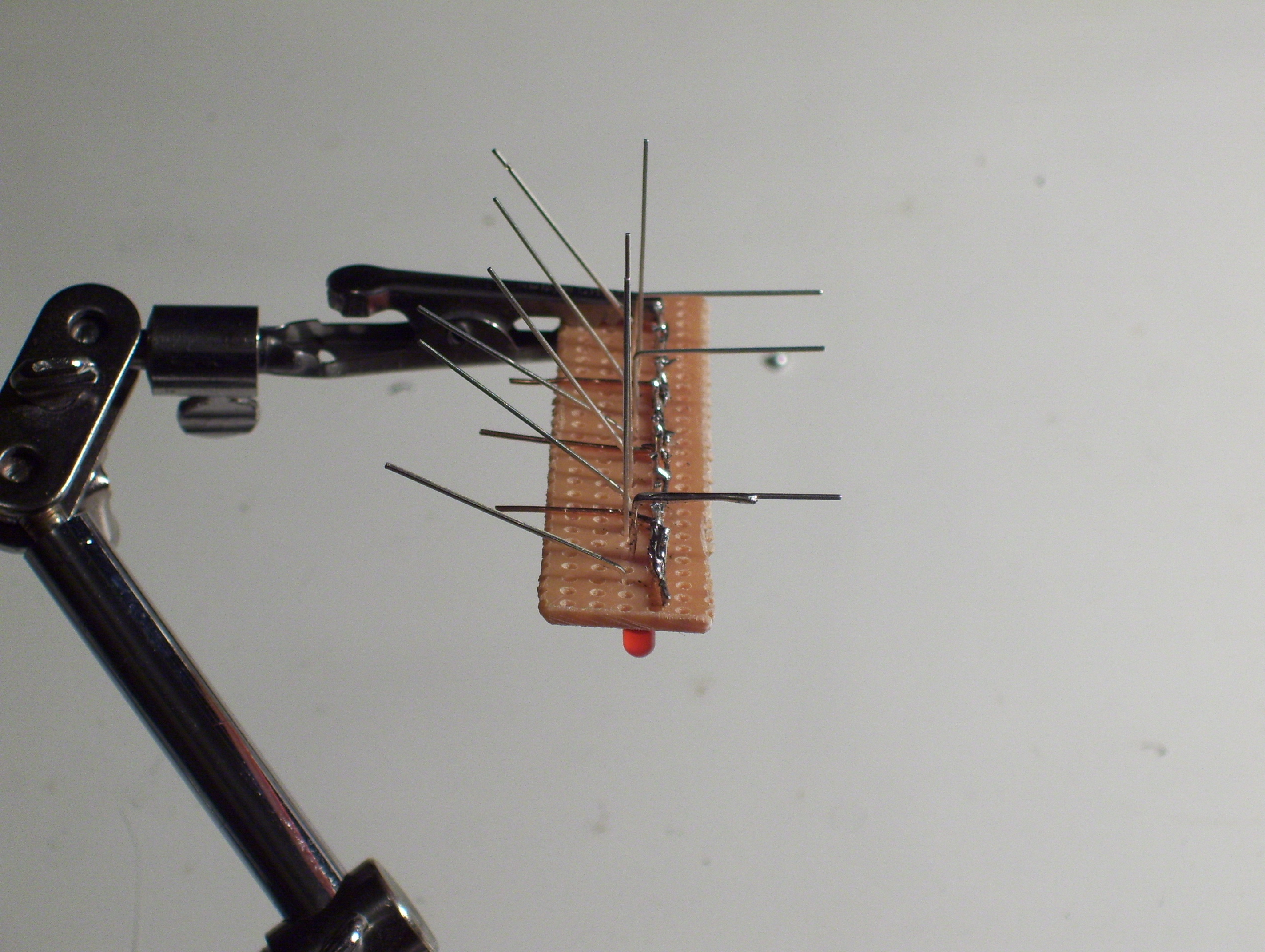
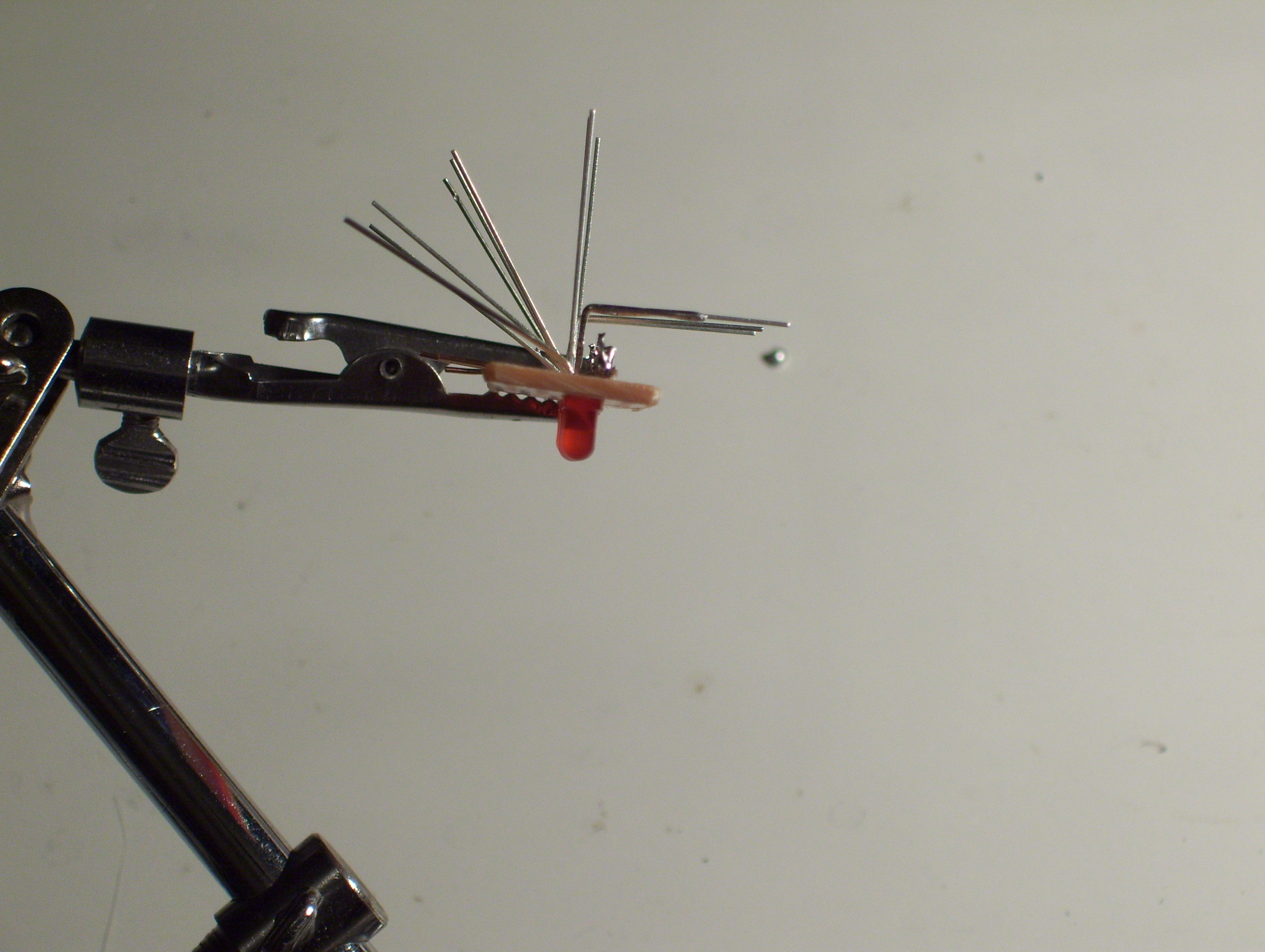
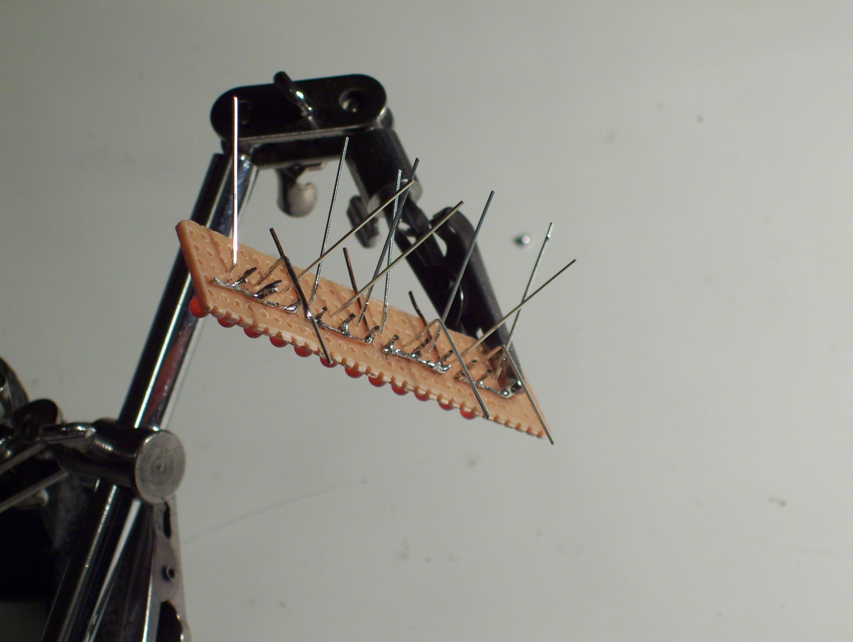
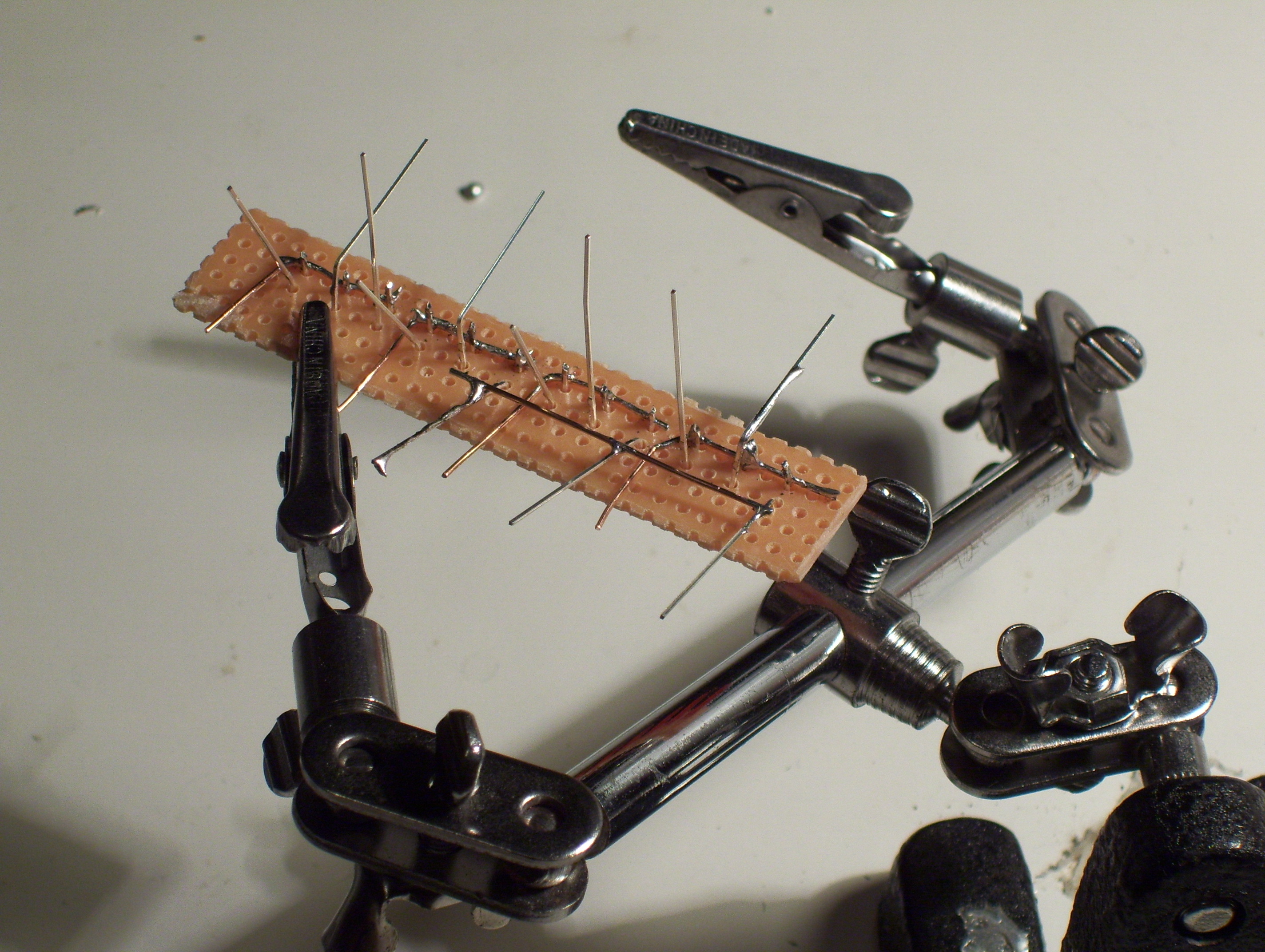
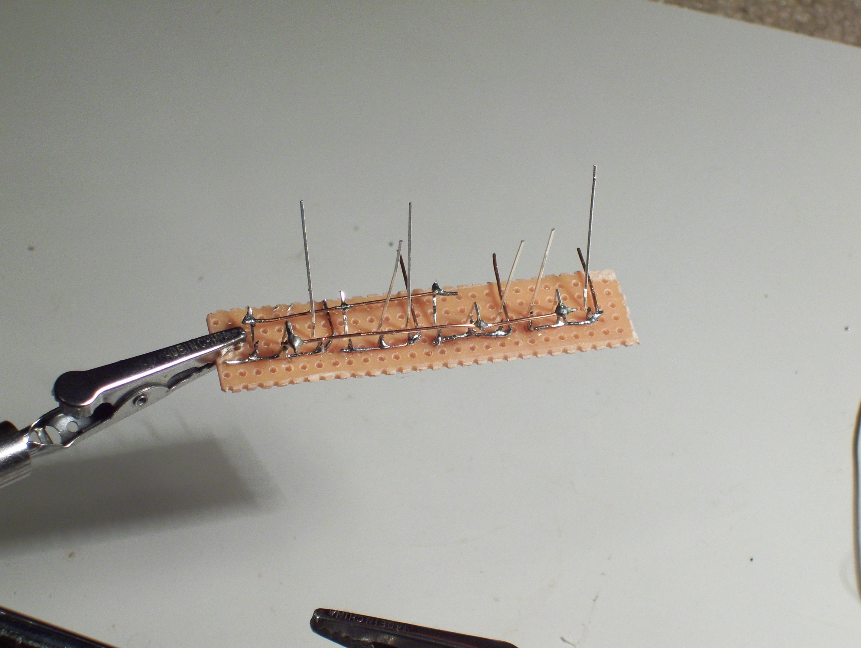
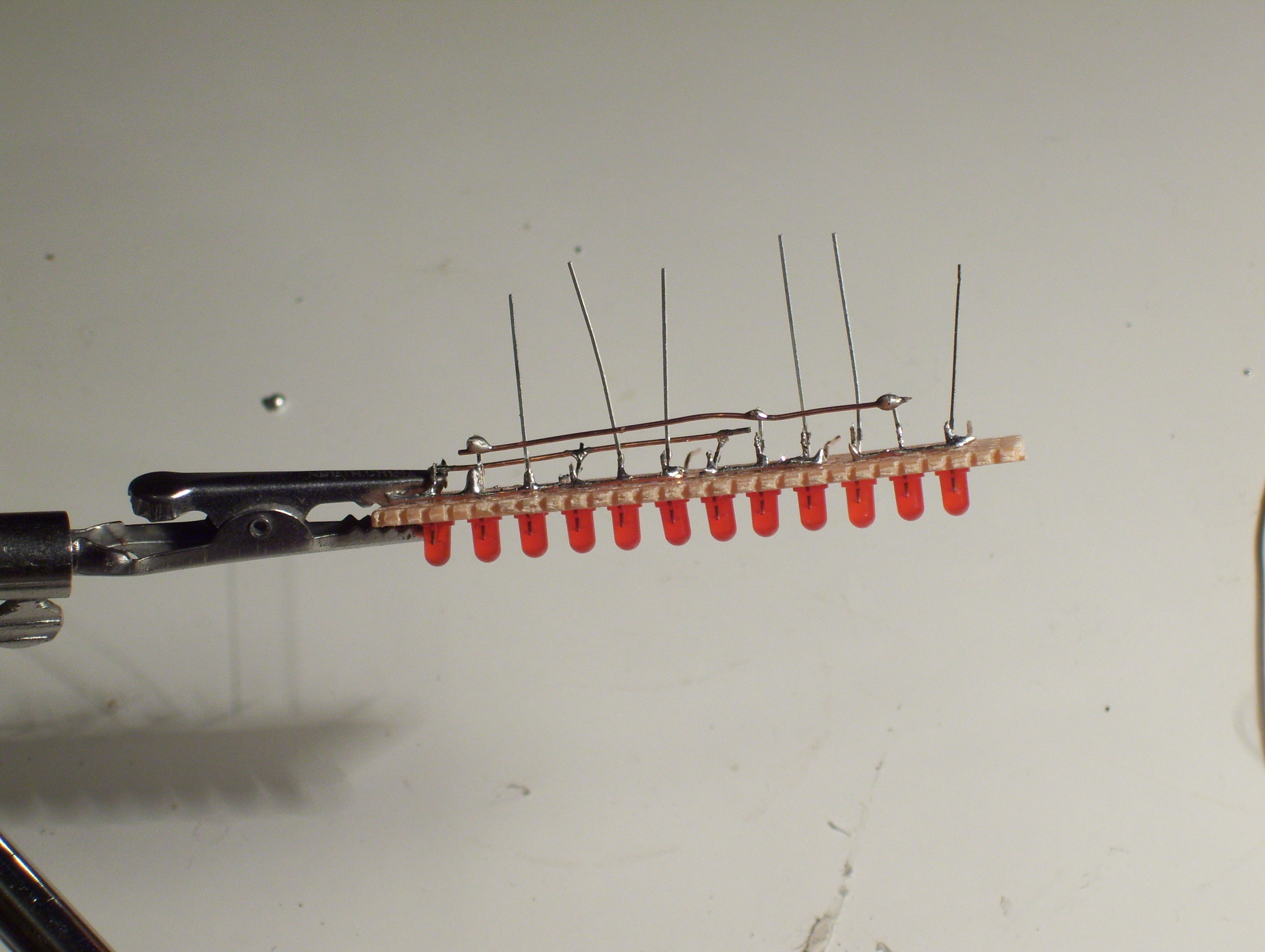
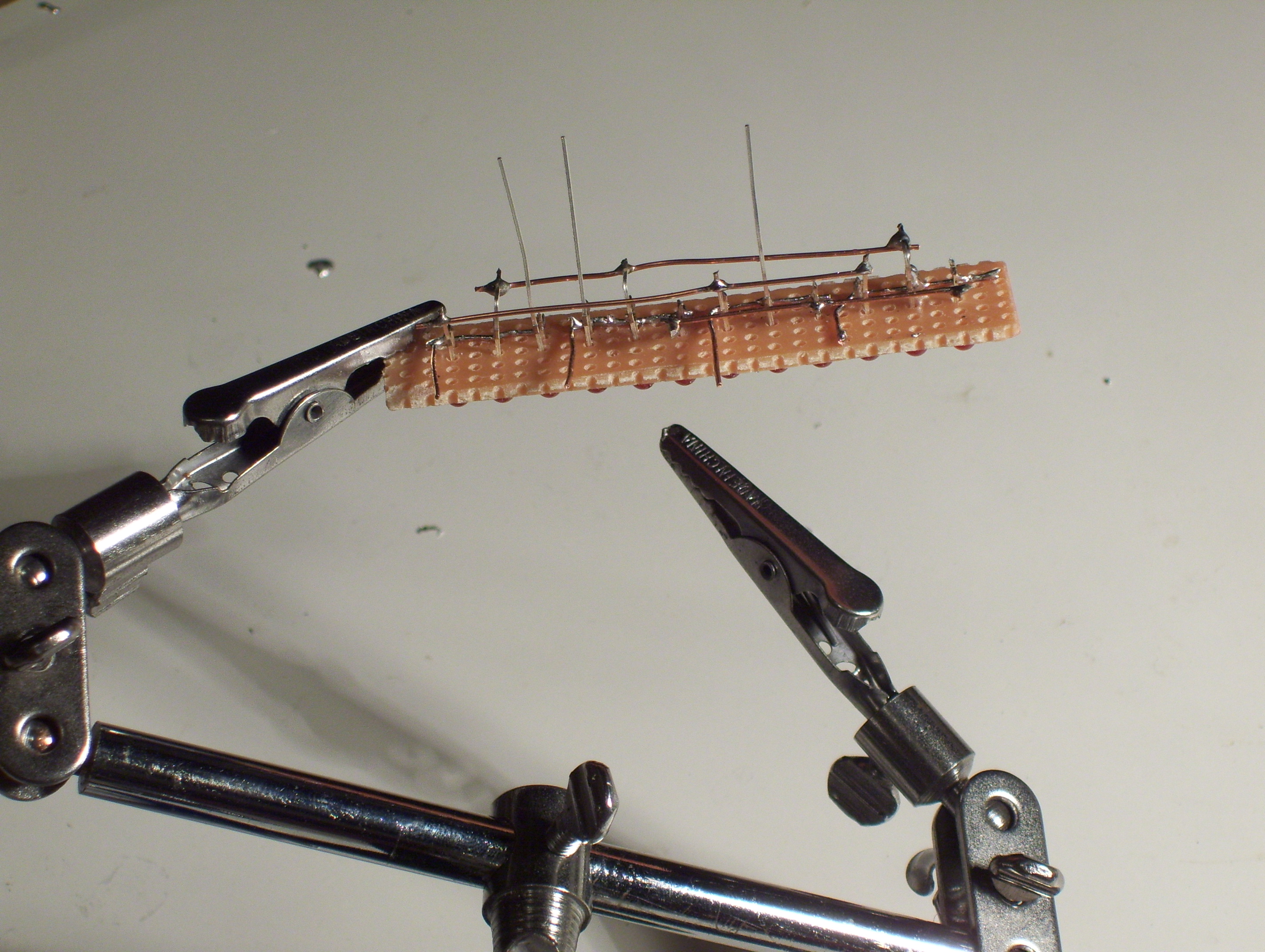
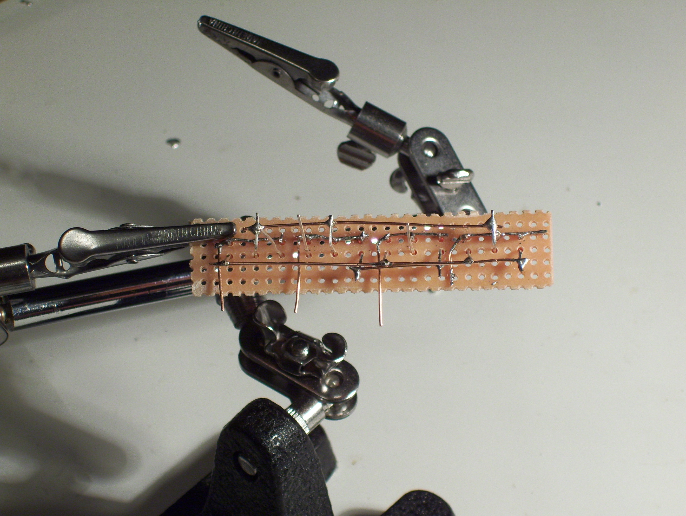
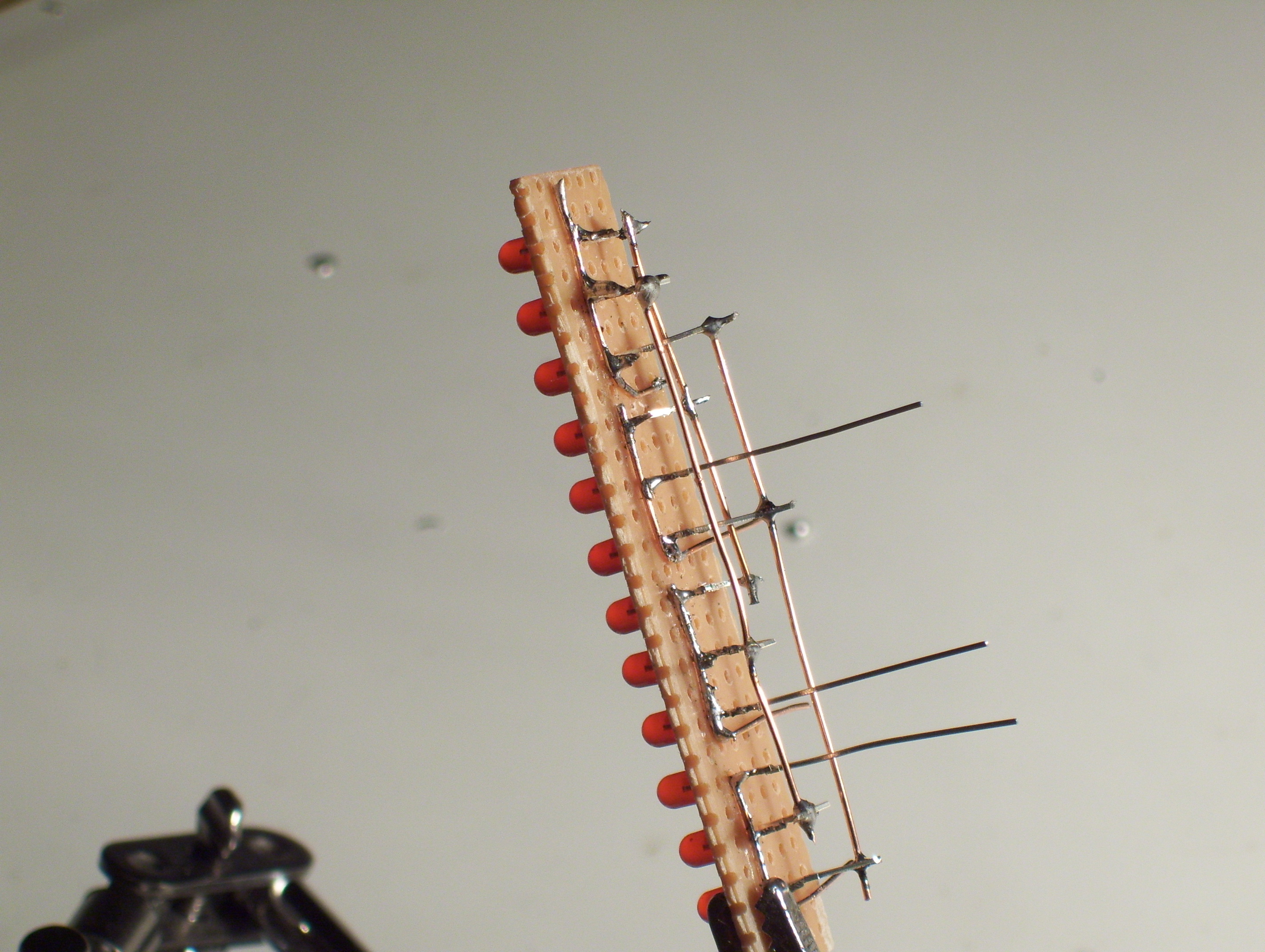
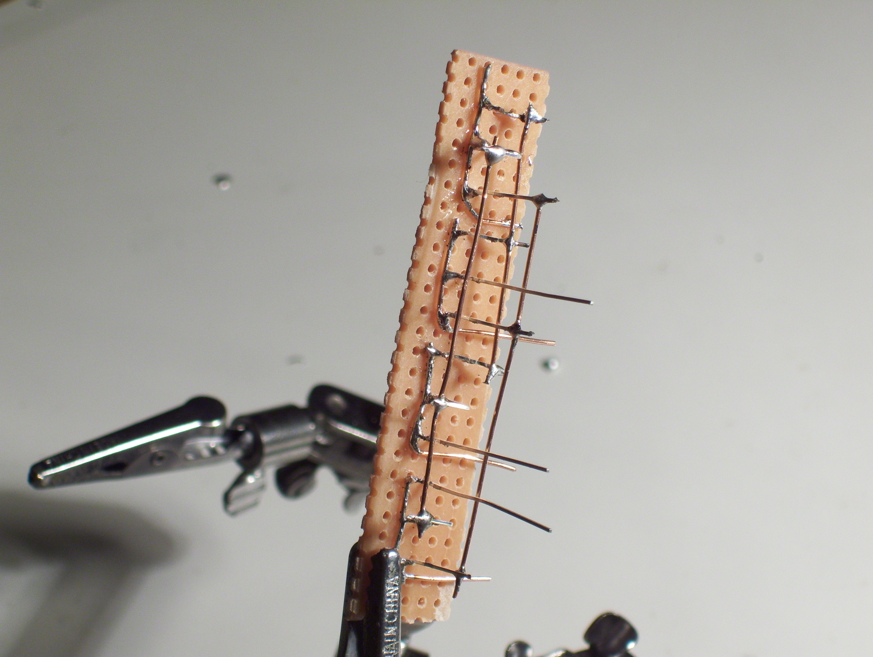
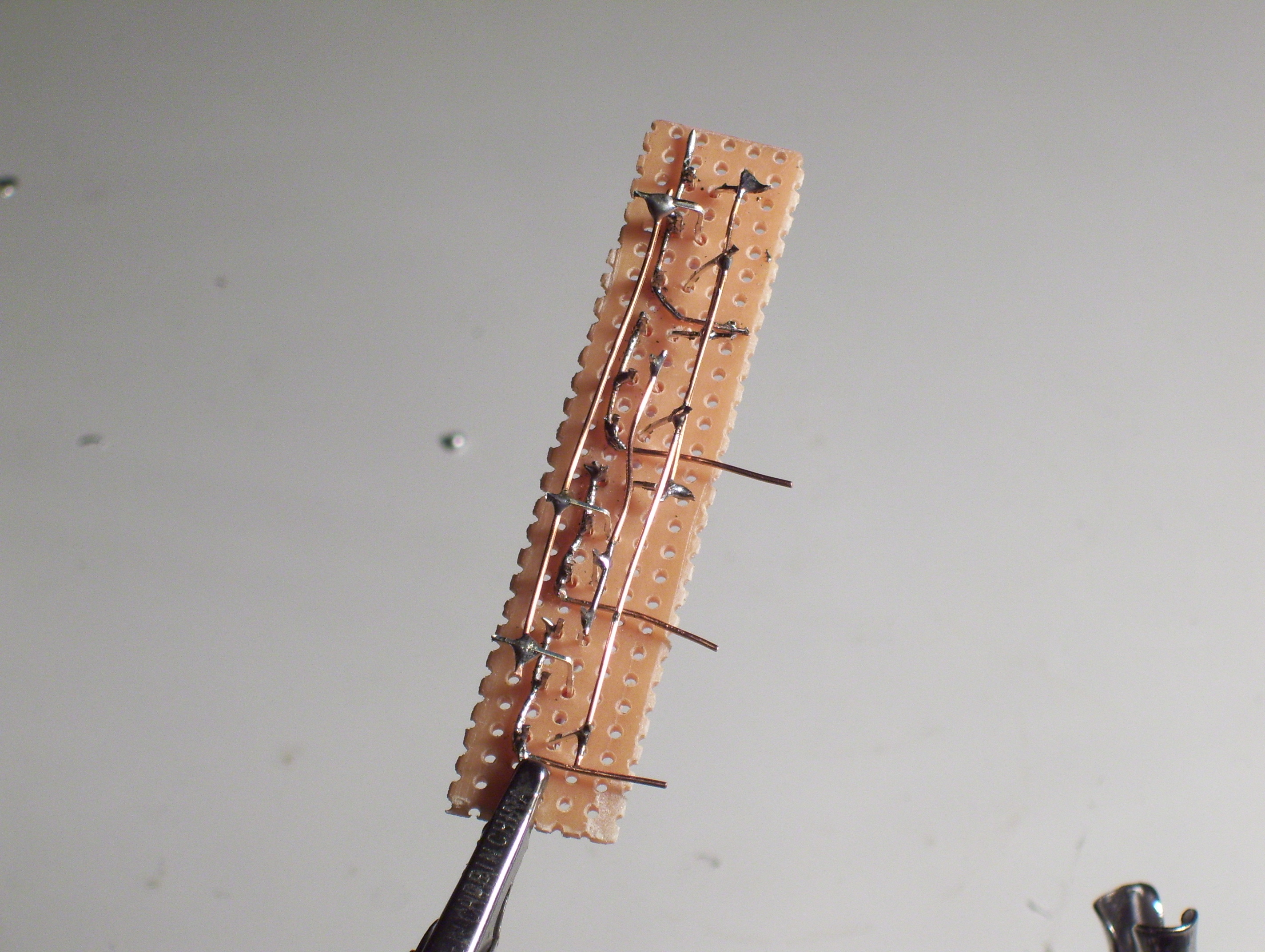
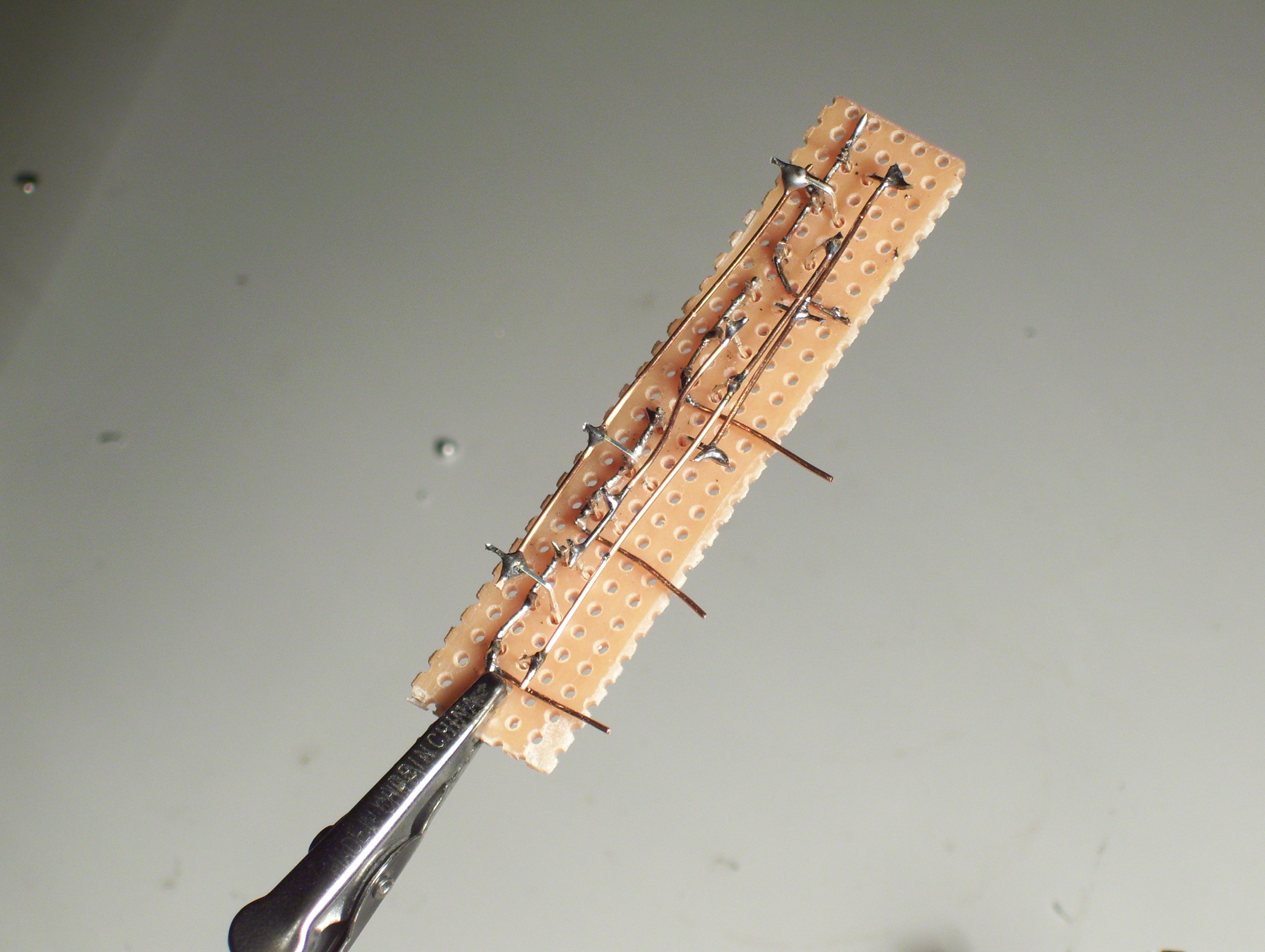
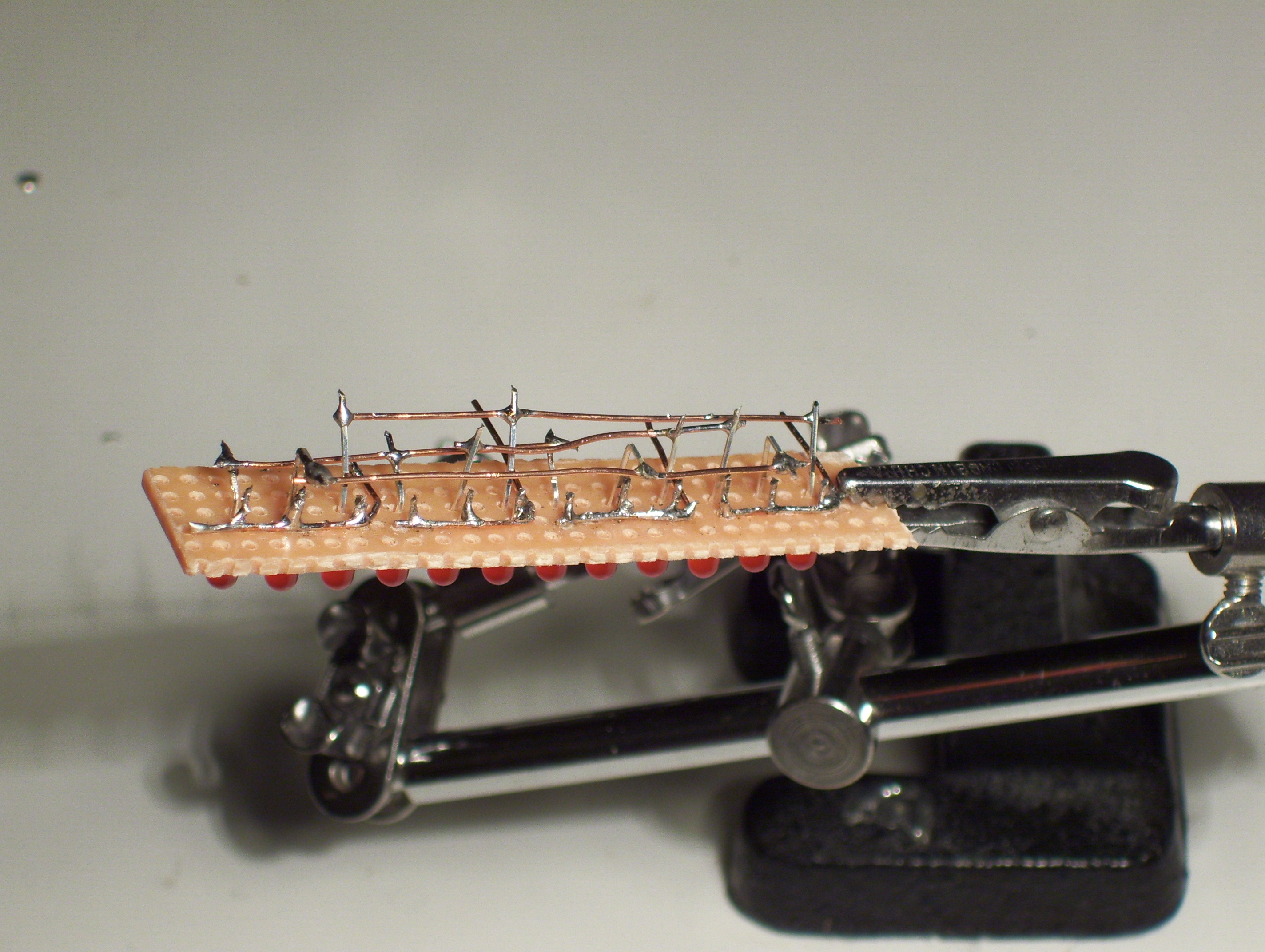
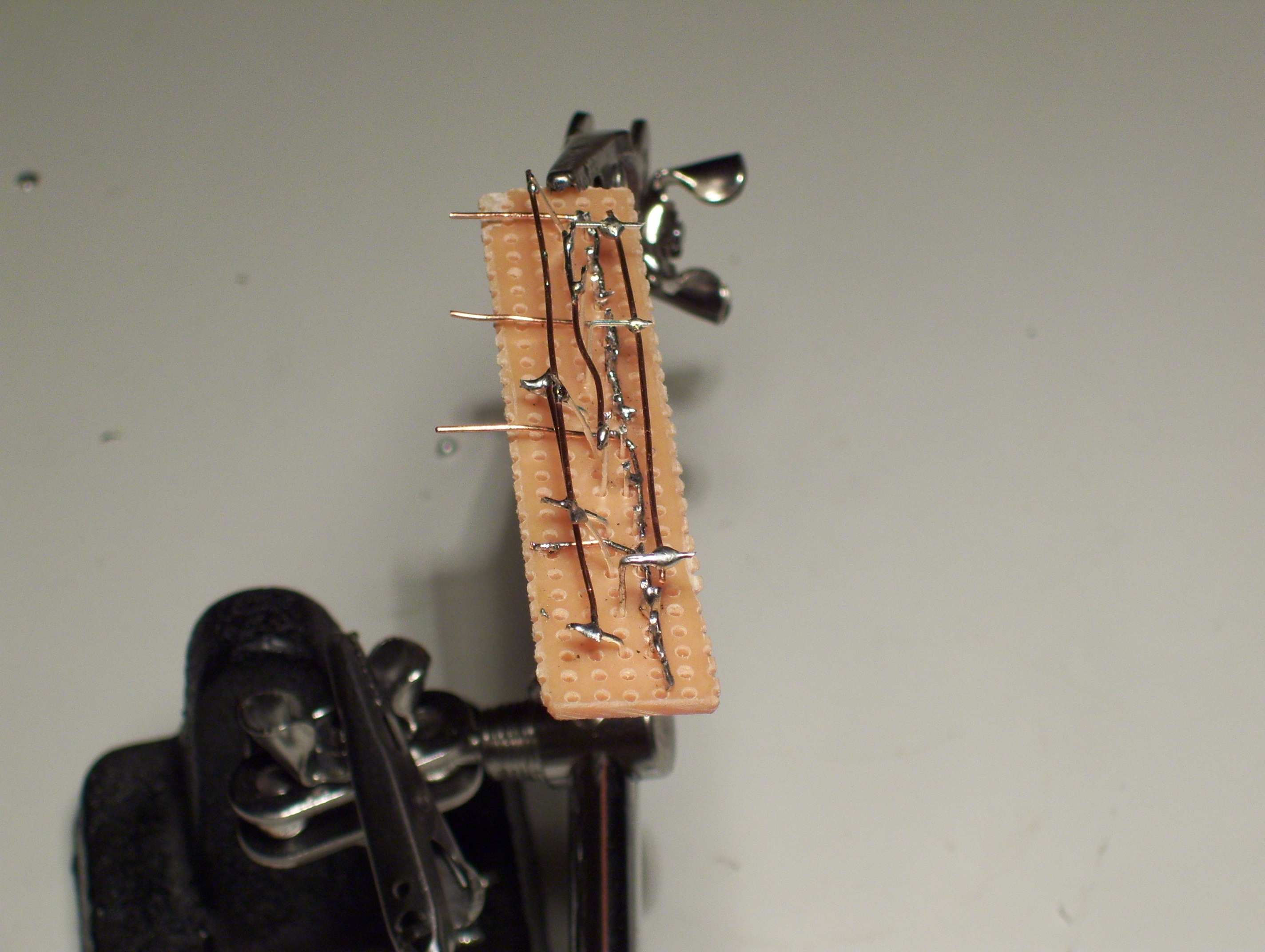

Main Points:
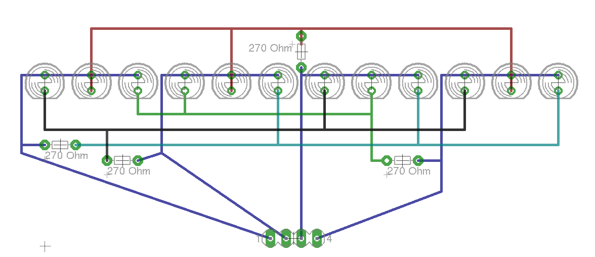
Not much to say here just solder the 4 rows & make sure to avoid any bridges in the wires. You should have 4 rows that have only 3 connections to it, one from each group with one group not attached. I tried to make the schematic as close to the wiring as possible, so that might make what I'm talking about a little easier to understand. It's is the last picture on this step.
Not much to say here just solder the 4 rows & make sure to avoid any bridges in the wires. You should have 4 rows that have only 3 connections to it, one from each group with one group not attached. I tried to make the schematic as close to the wiring as possible, so that might make what I'm talking about a little easier to understand. It's is the last picture on this step.
Install Resistors
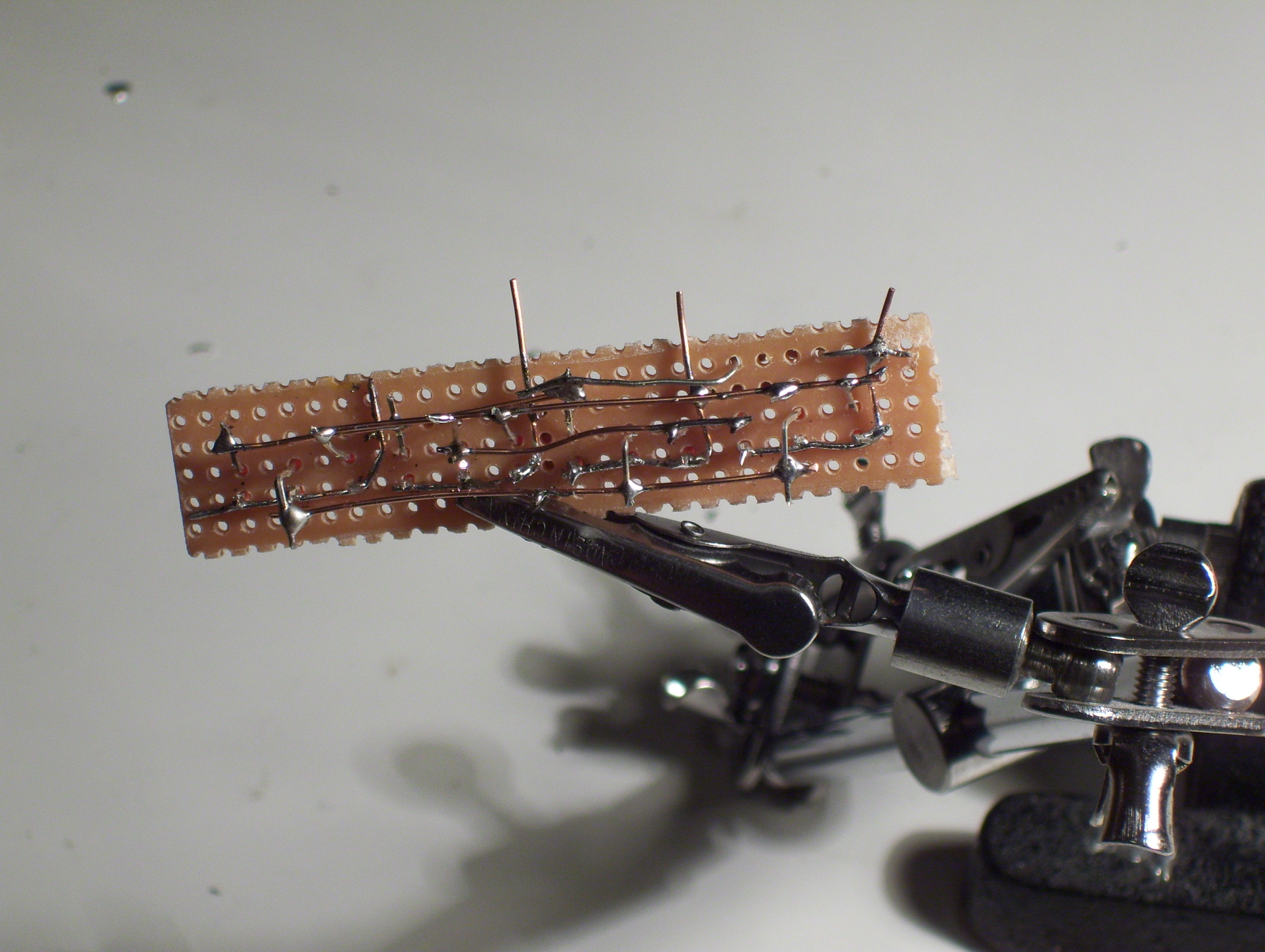
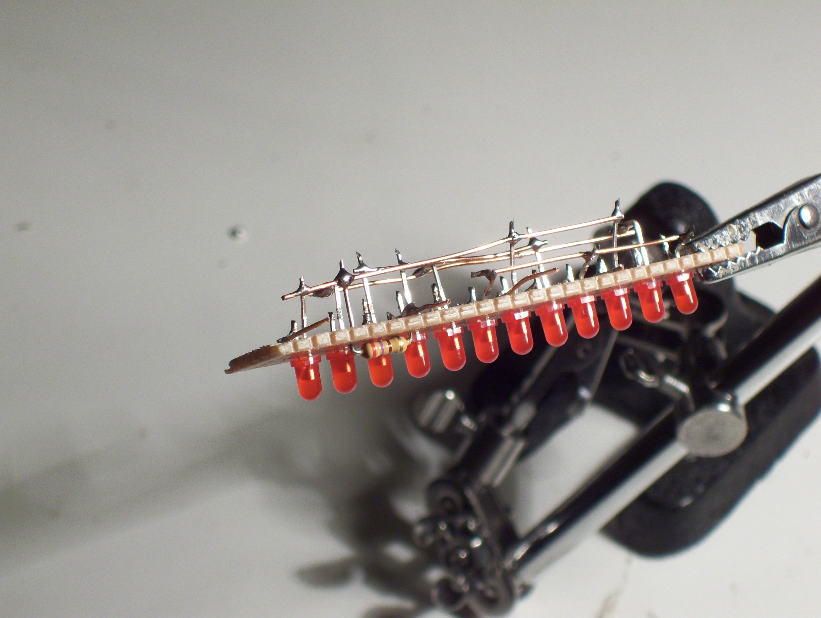
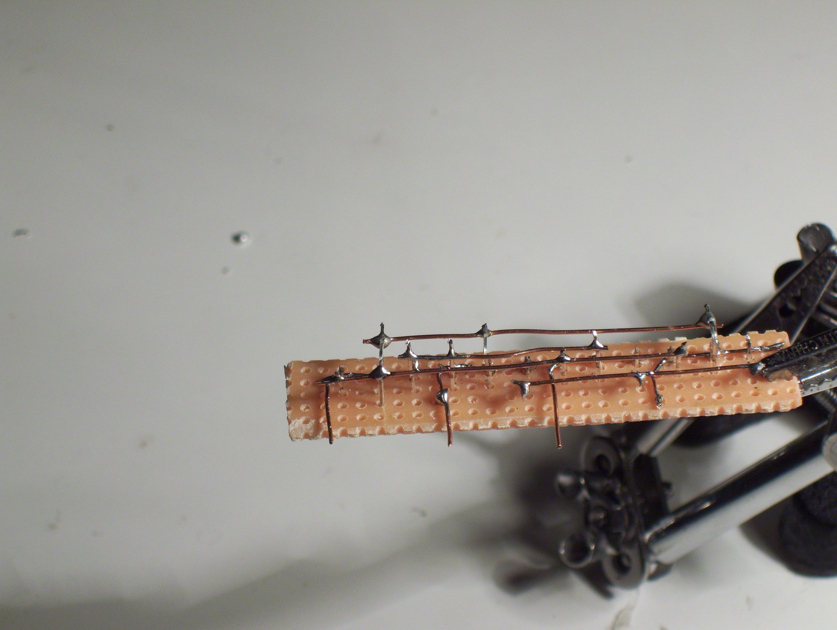
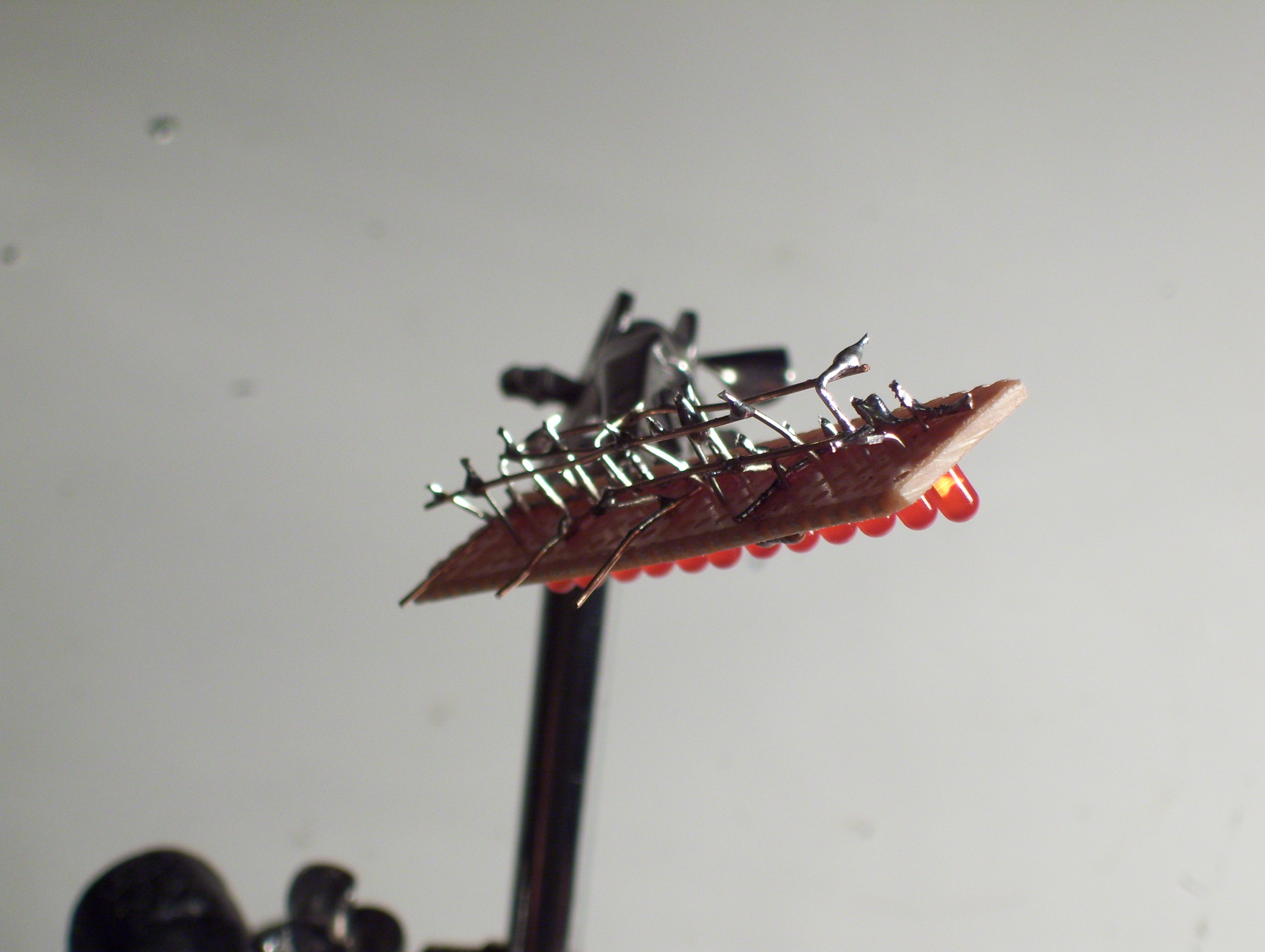
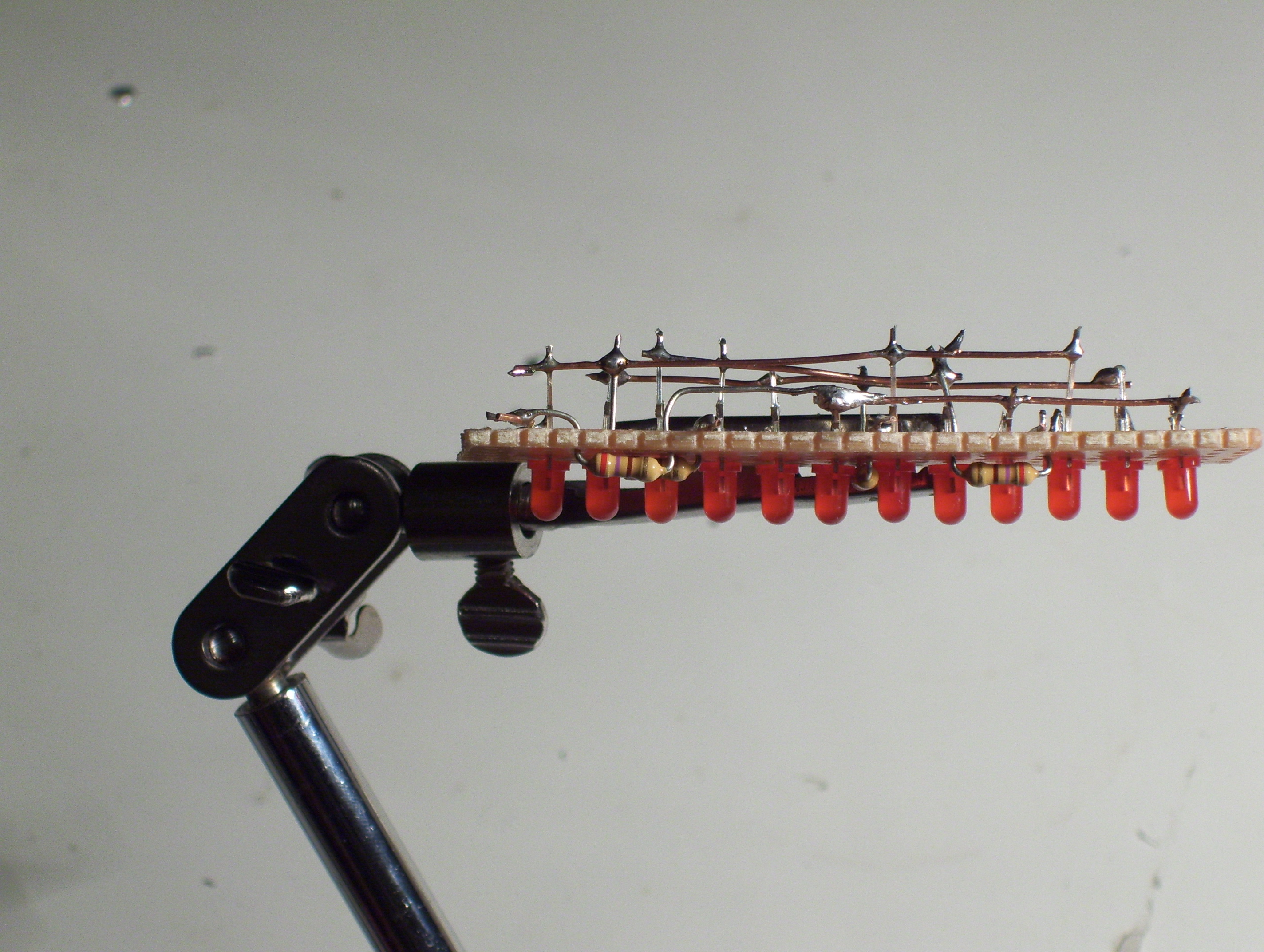

This is a little confusing. Hope I explained it well enough. There are more pictures of this in step 9.
Resistor end connections:
1) One end connected to row 1. The other to group 4
2) One end connected to row 2. The other to group 3
3) One end connected to row 4. The other to group 2
4) One end connected to row 3. The other to group 1
Resistor end connections:
1) One end connected to row 1. The other to group 4
2) One end connected to row 2. The other to group 3
3) One end connected to row 4. The other to group 2
4) One end connected to row 3. The other to group 1
Add the Control Wires
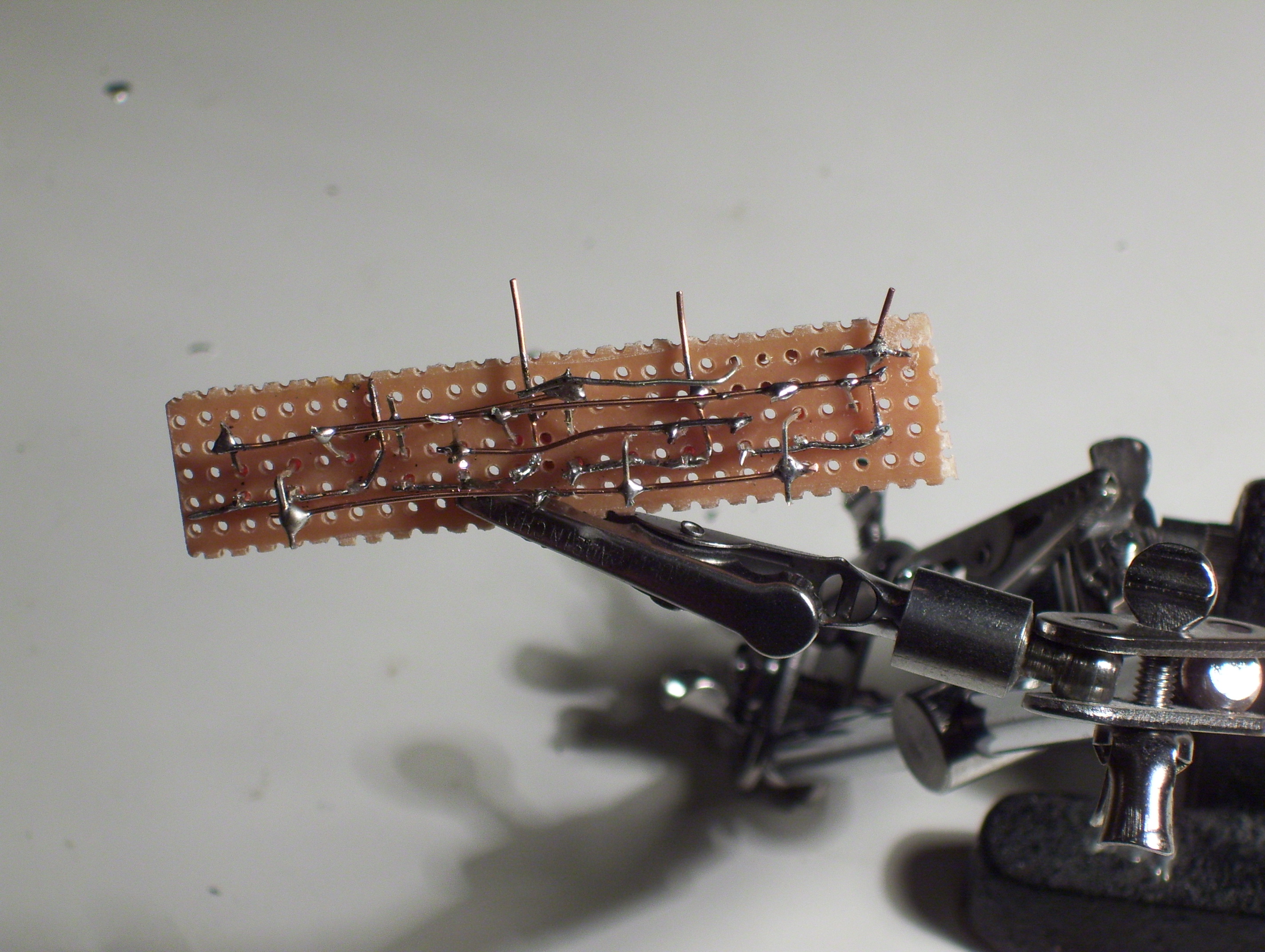
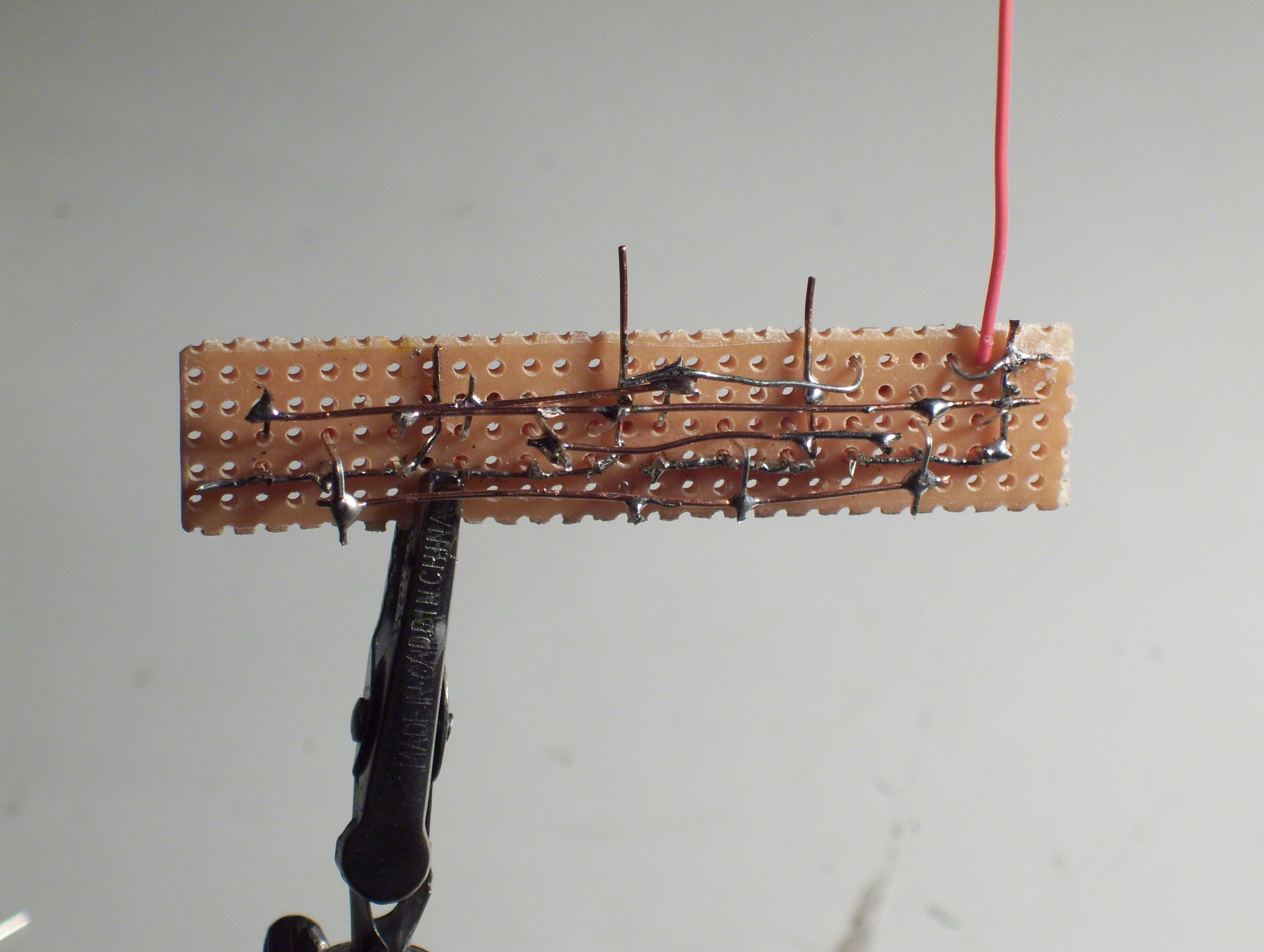
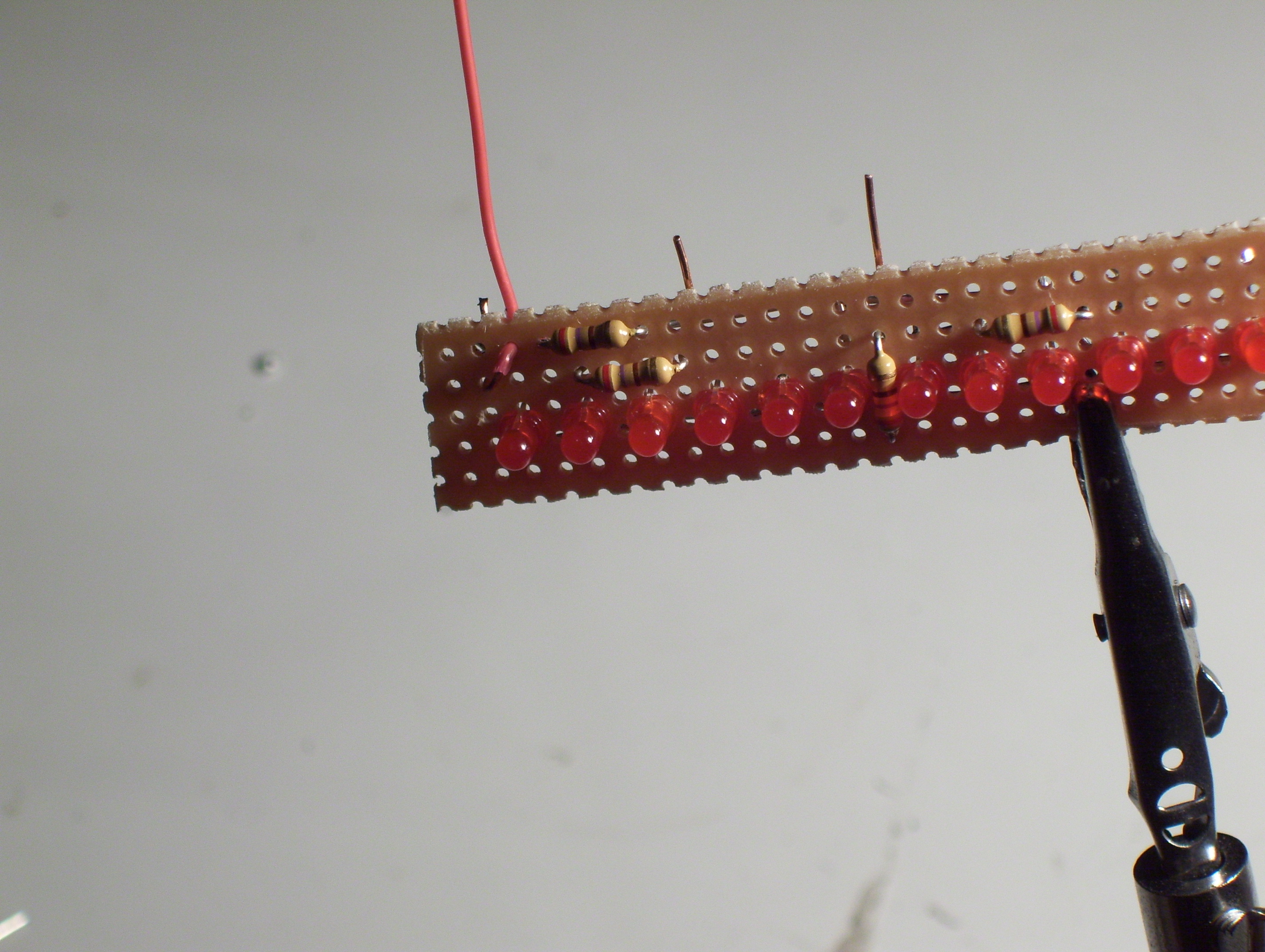
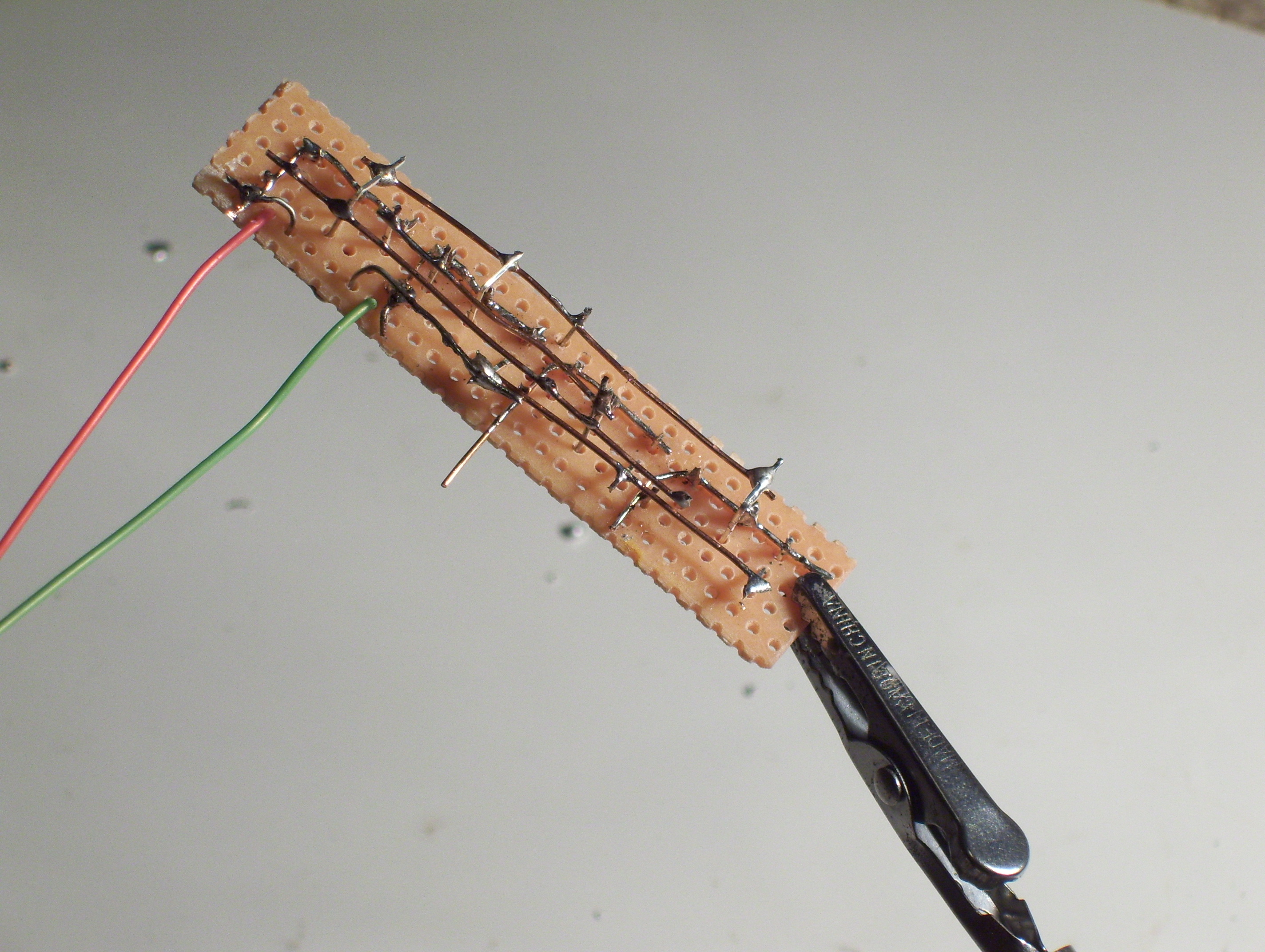
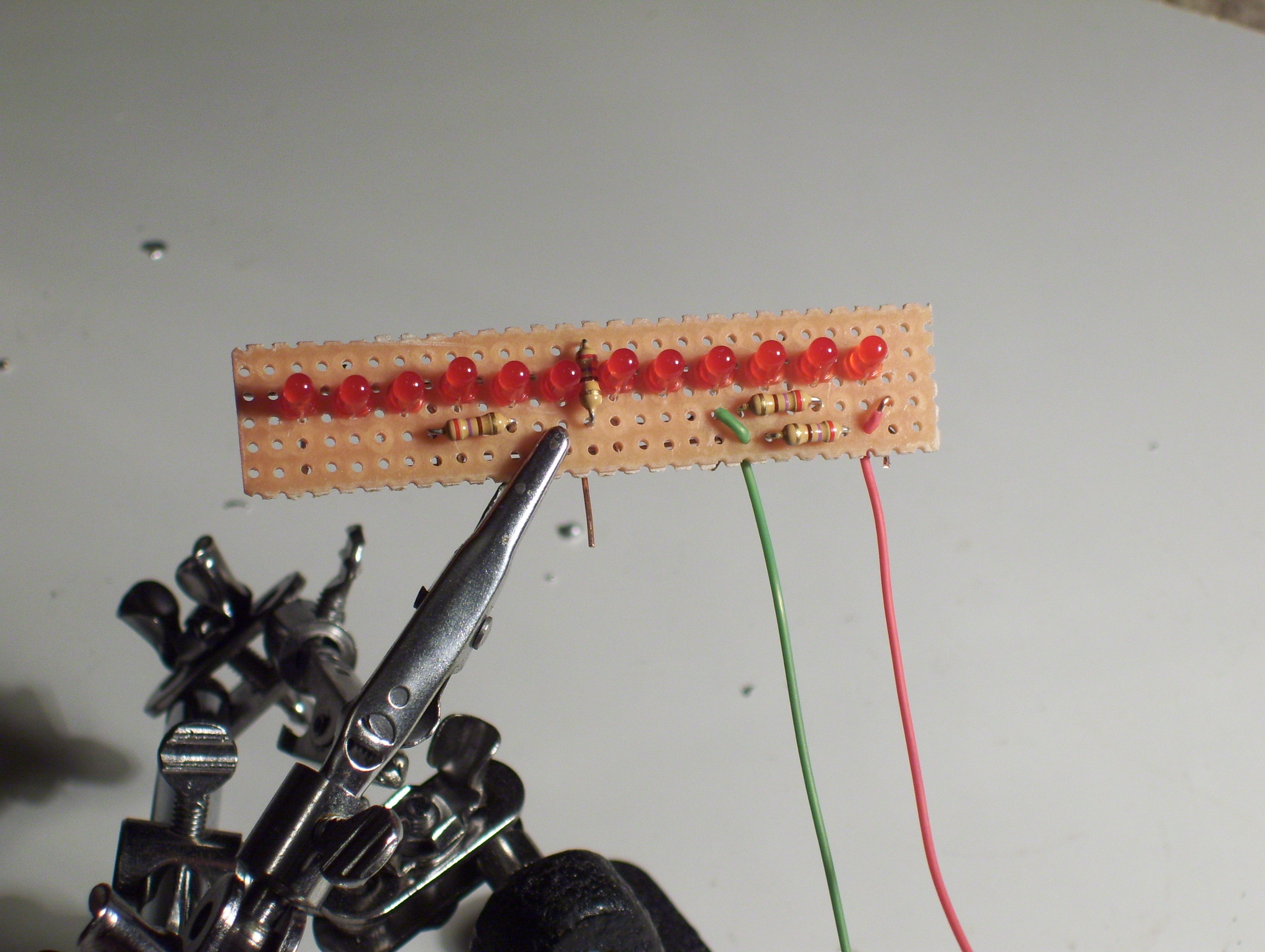
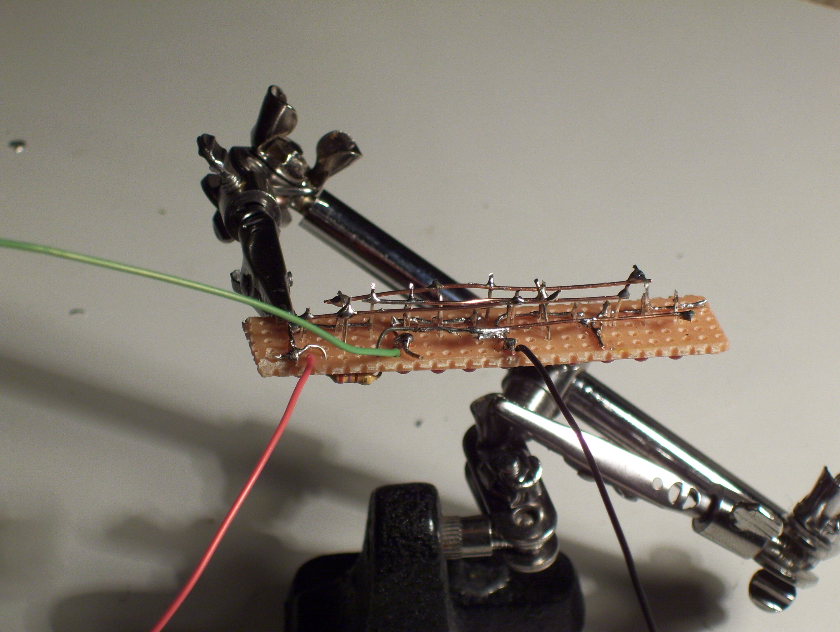
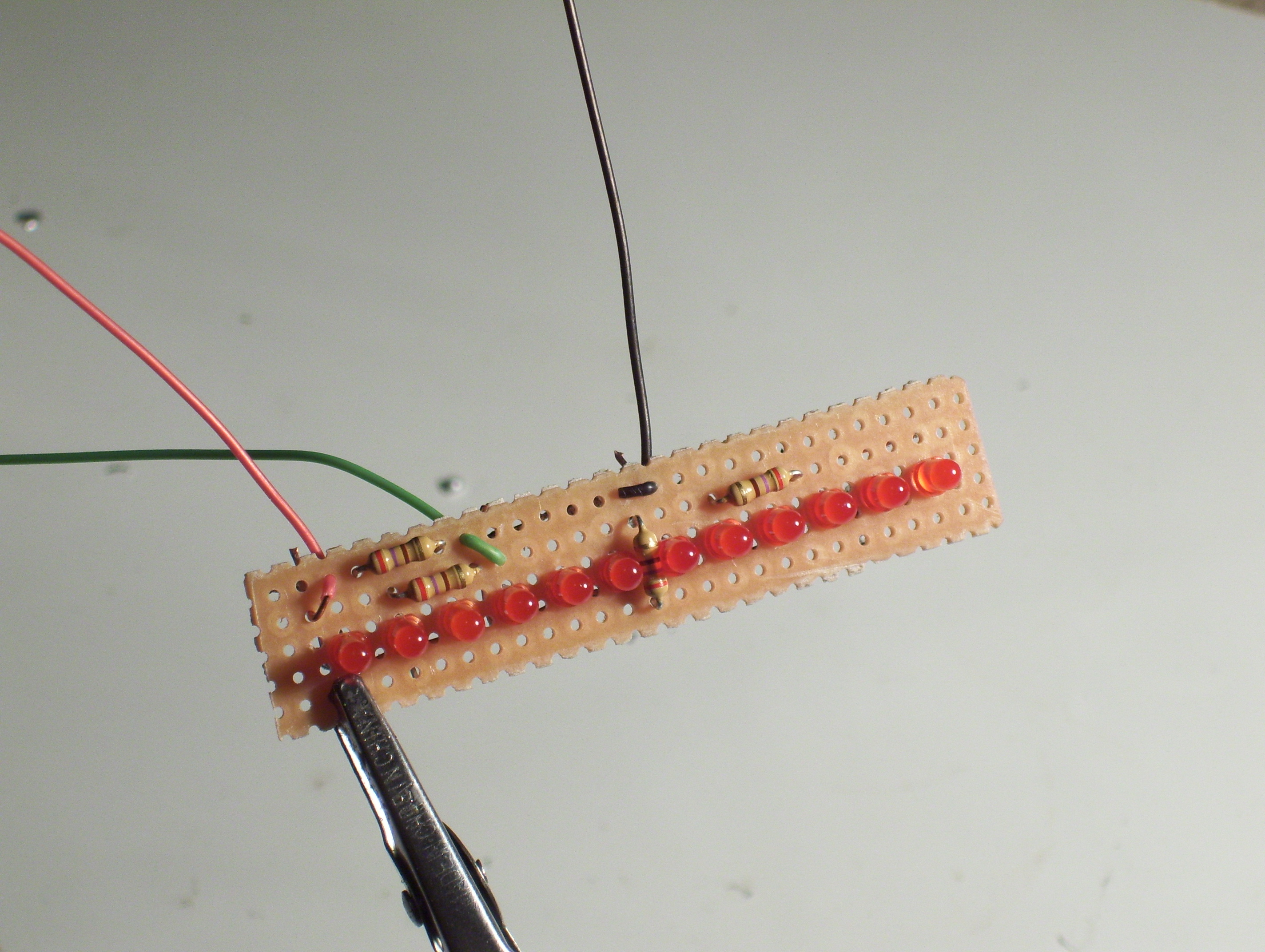
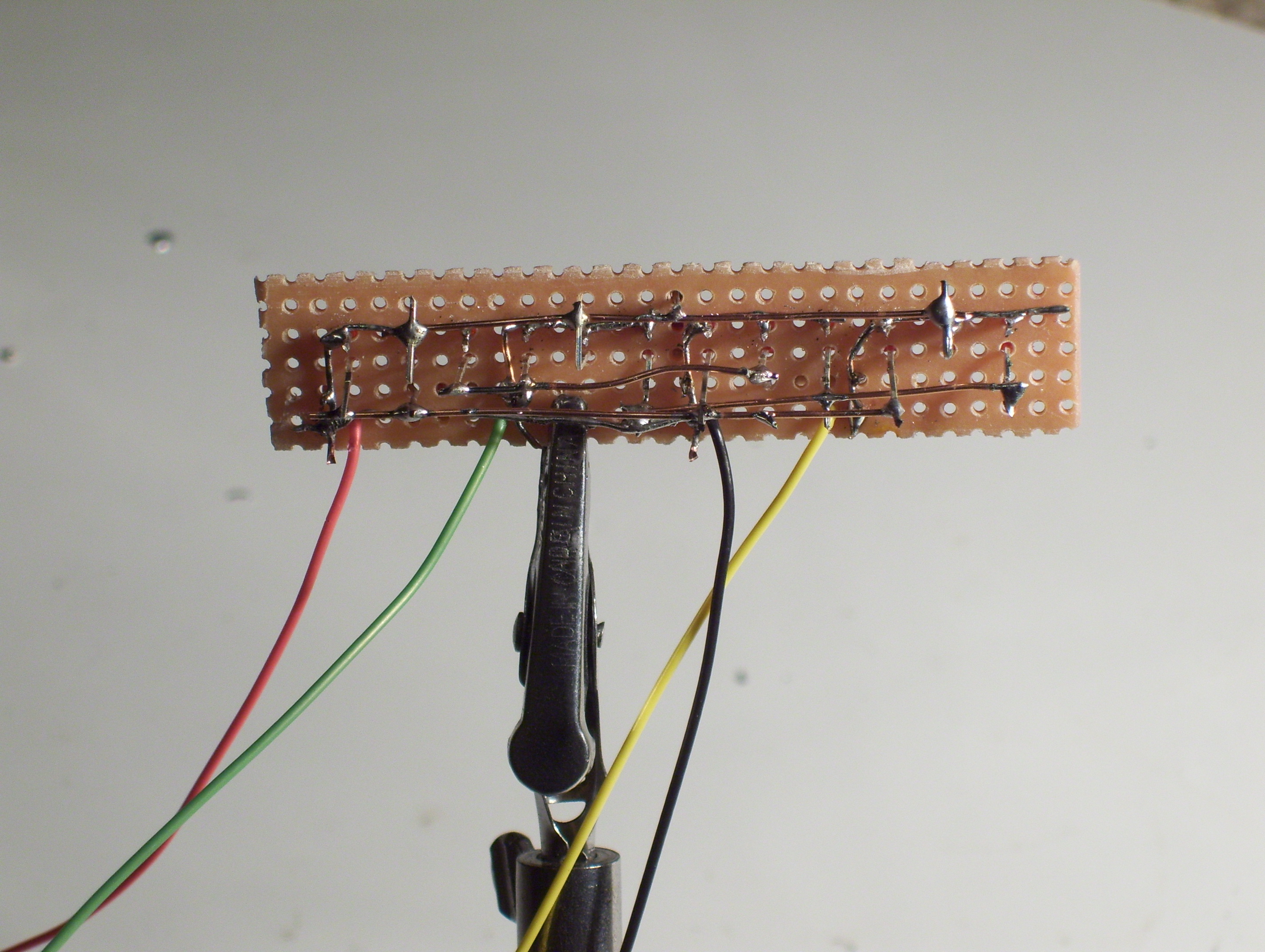
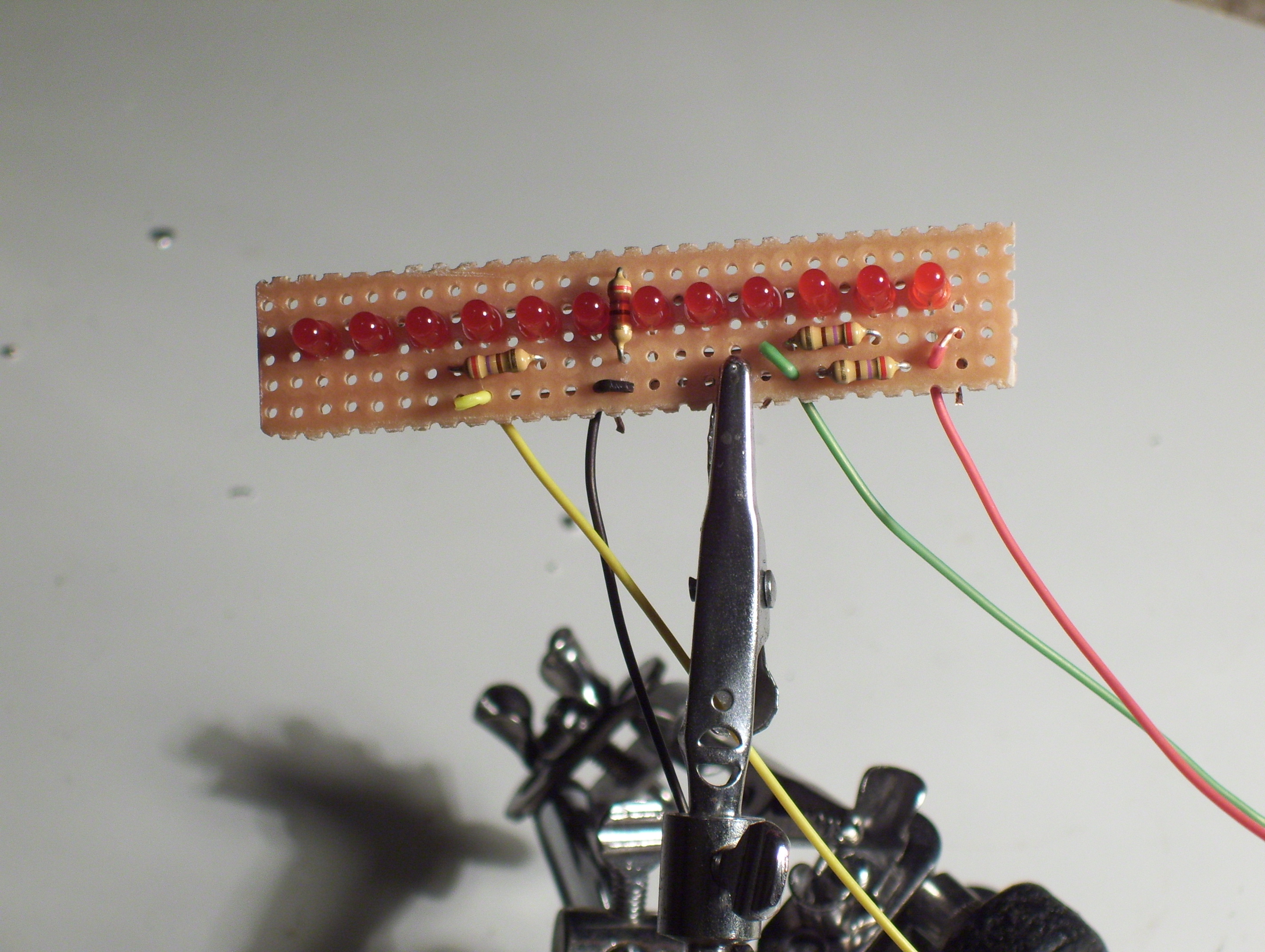
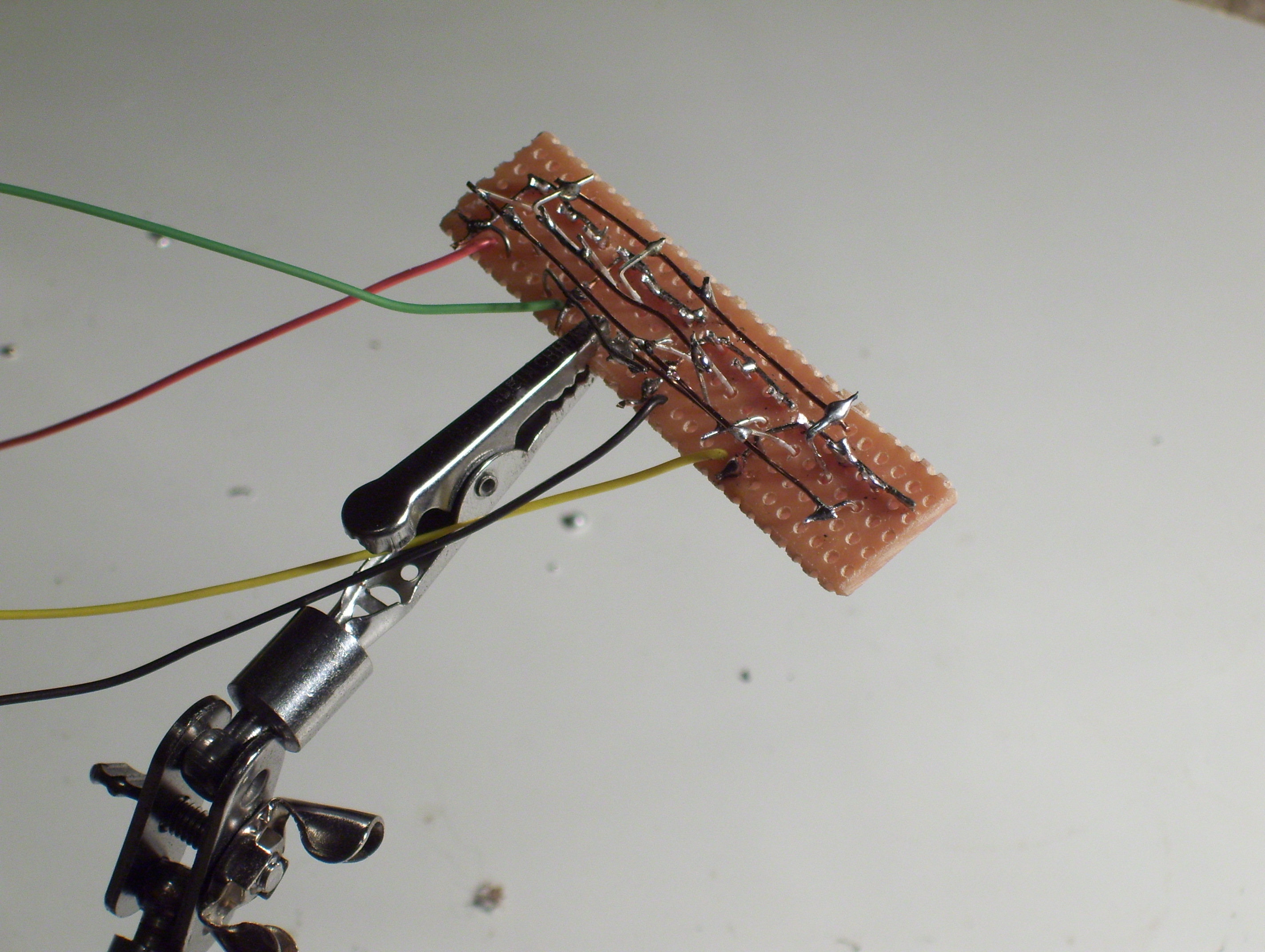
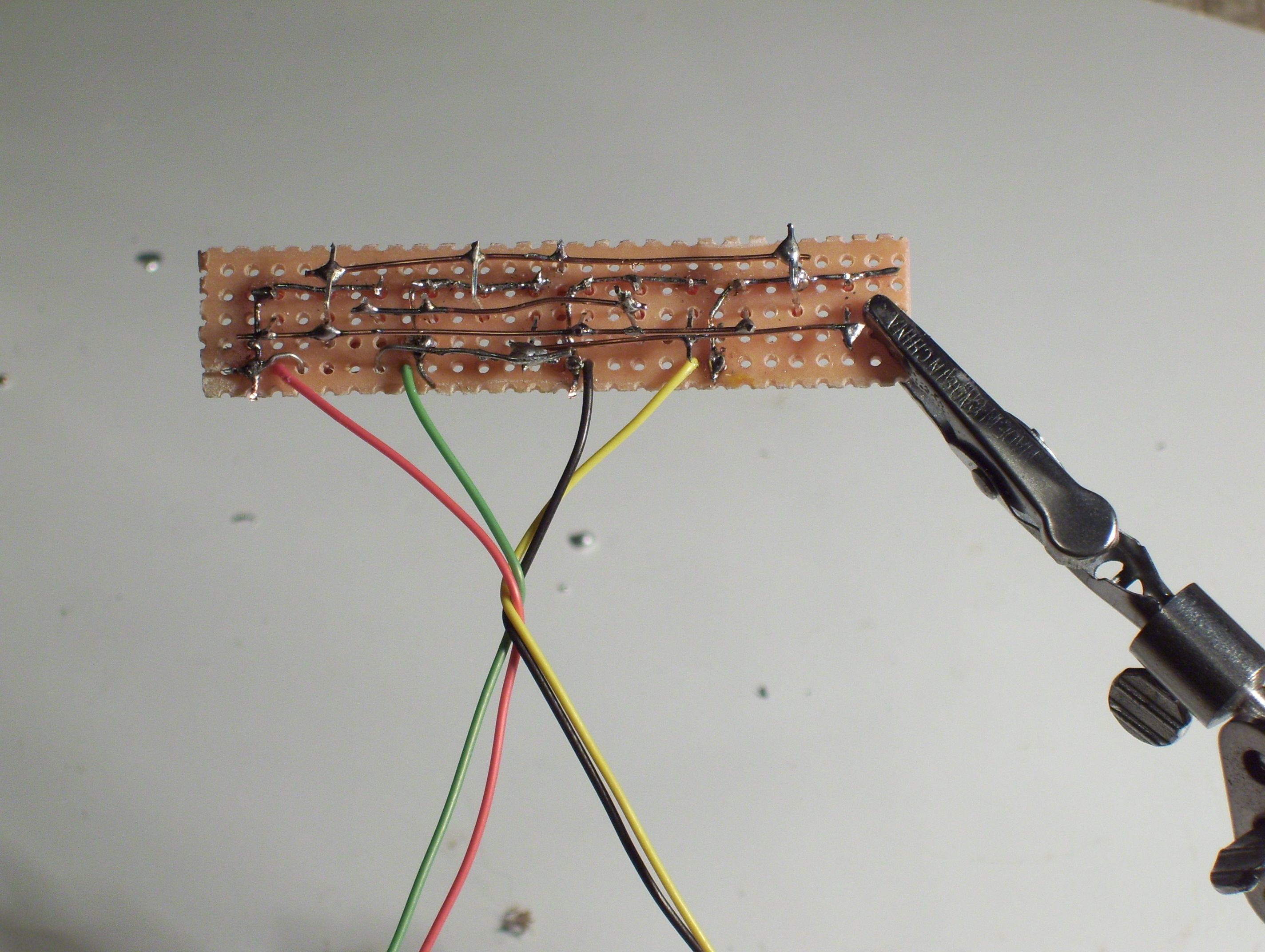
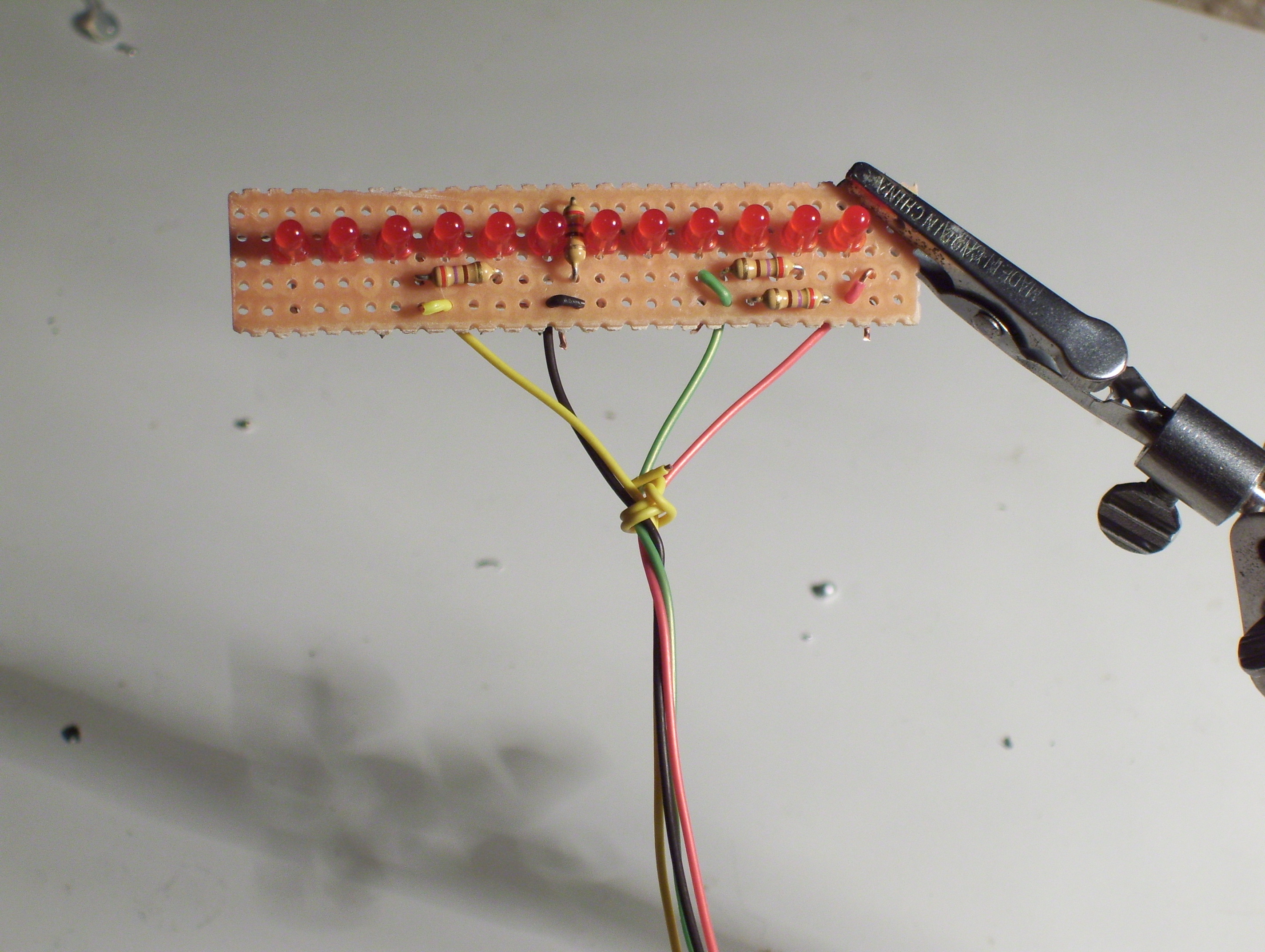
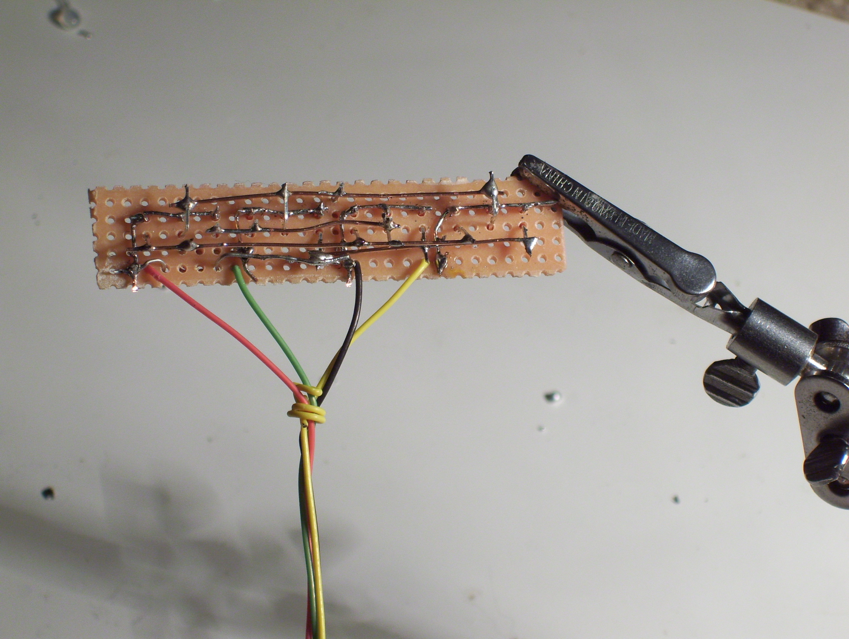
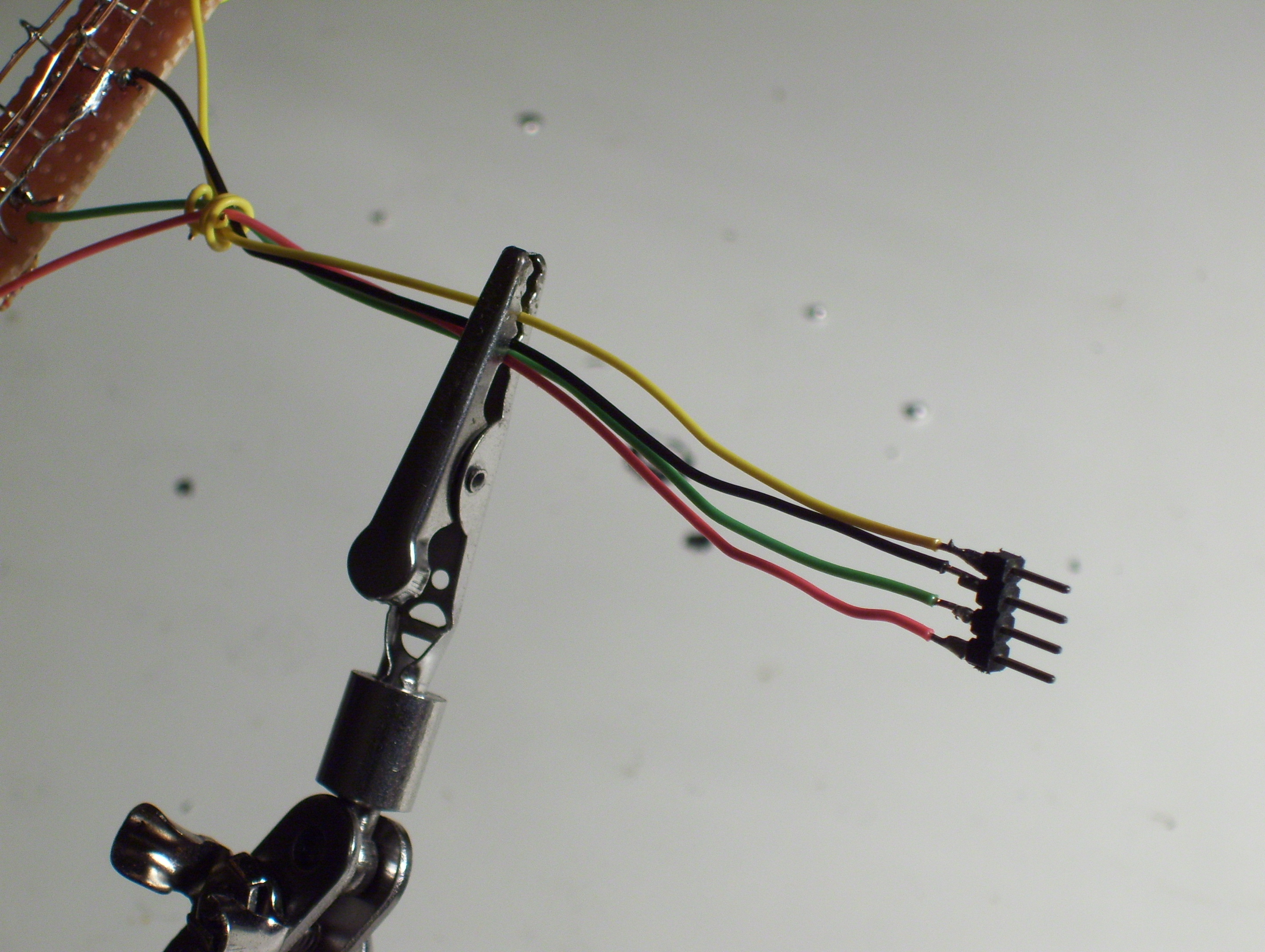
This is probably one of the easiest steps! All you are doing is soldering wires to the 4 groups.
I used some pieces of wire about 6 in long. They don't have to be different colors but it can be helpful if anything goes wrong & you need to debug the circuit. You don't need some header pins, but if you want some feel free to use them.
I used some pieces of wire about 6 in long. They don't have to be different colors but it can be helpful if anything goes wrong & you need to debug the circuit. You don't need some header pins, but if you want some feel free to use them.
Coding the Arduino
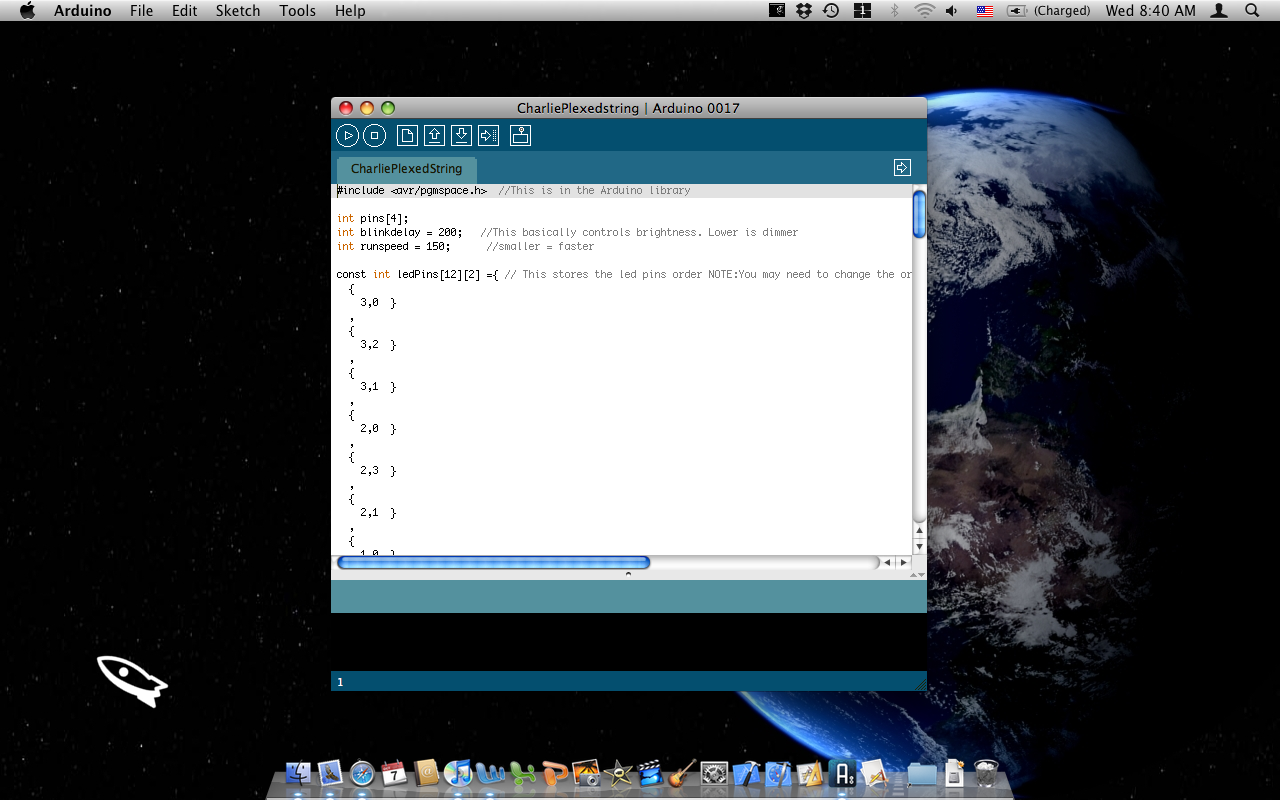
Here's some basic steps to program your arduino.
1) Download the source code from below
2) Open the file in the Arduino IDE
3) Press the "Upload to I/O Board" button
4) Once the program is uploaded it will start running
Note:You may need to change a few things in the "const int ledPins[12][2] ={" array if the led's turn on, out of order.
I tried to add a good amount of comments to the code, but if you have any questions, please ask them.
Downloads
Have Fun!!!

This shouldn't be to hard, but it might be
If you have any comments, questions &/or suggestions please ask them!
If you have any comments, questions &/or suggestions please ask them!
Extra Pictures
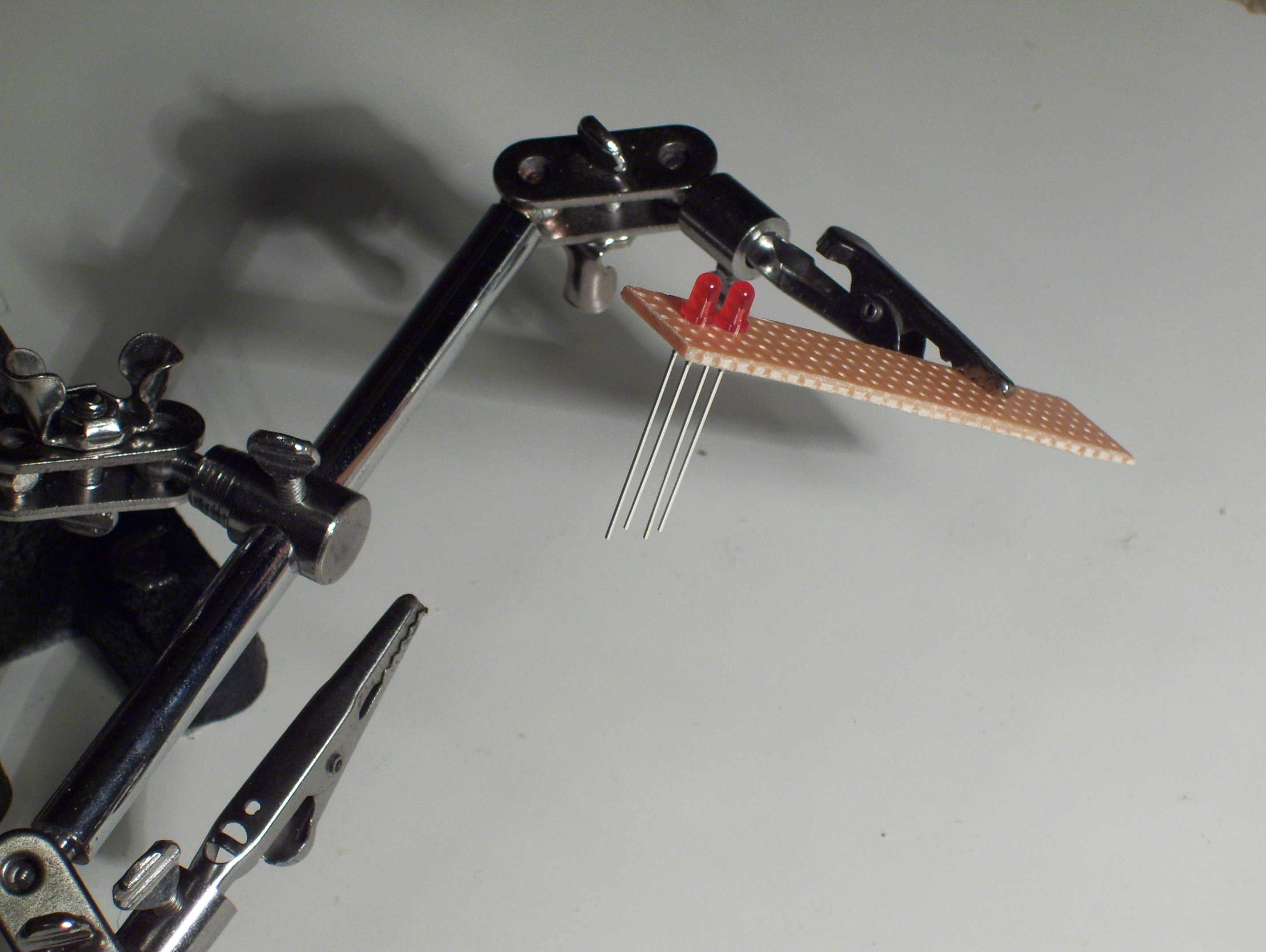
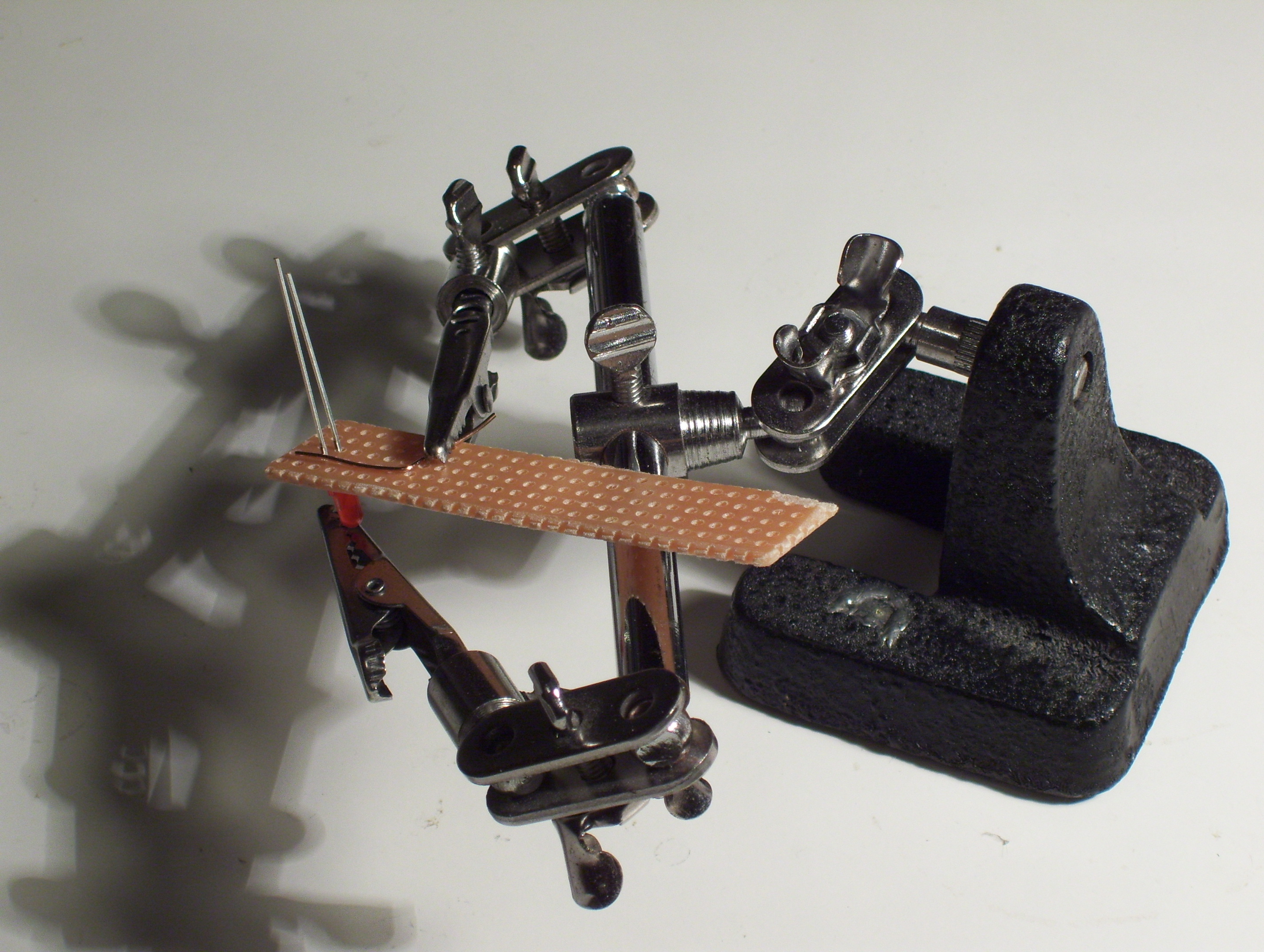
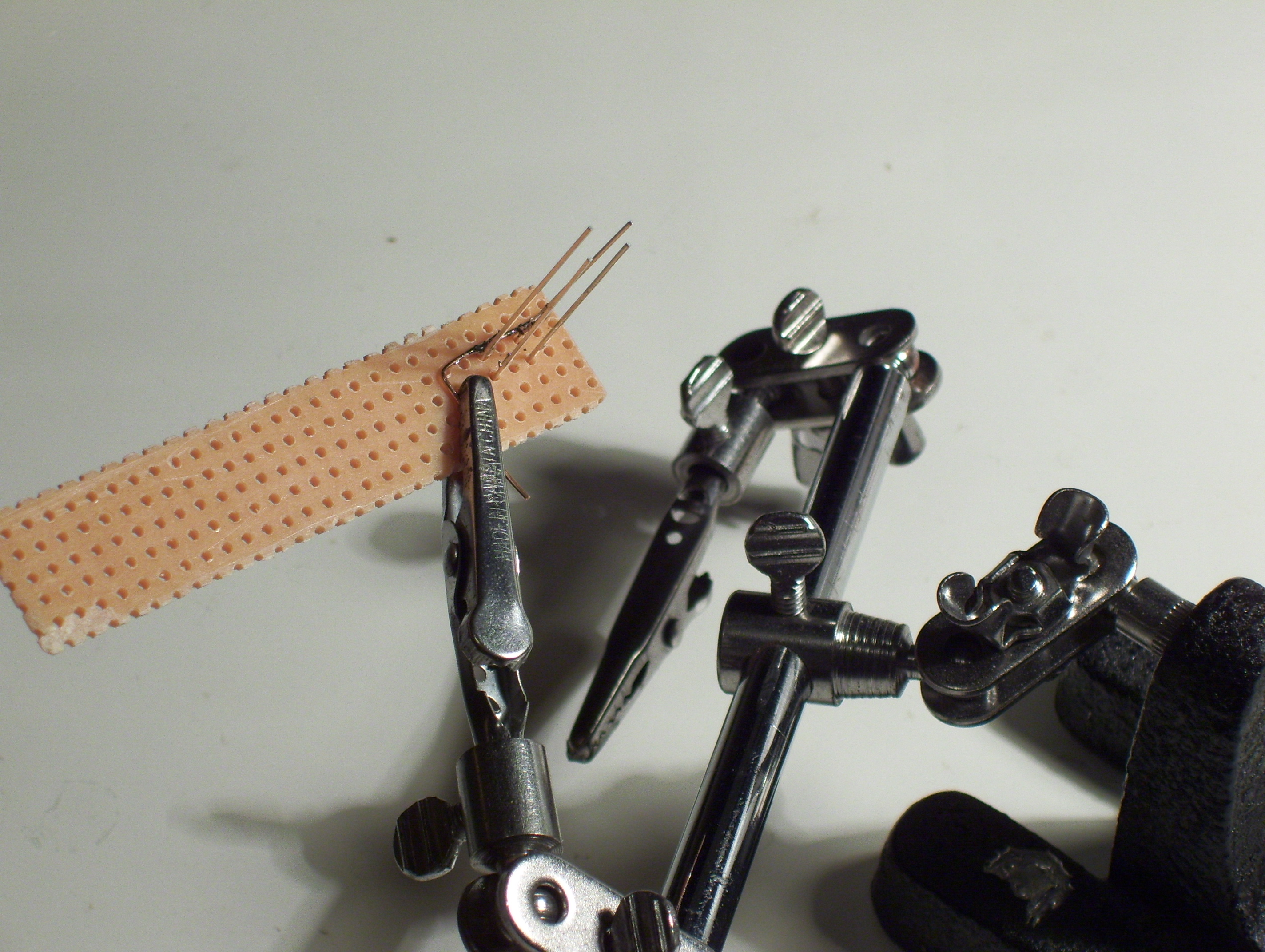
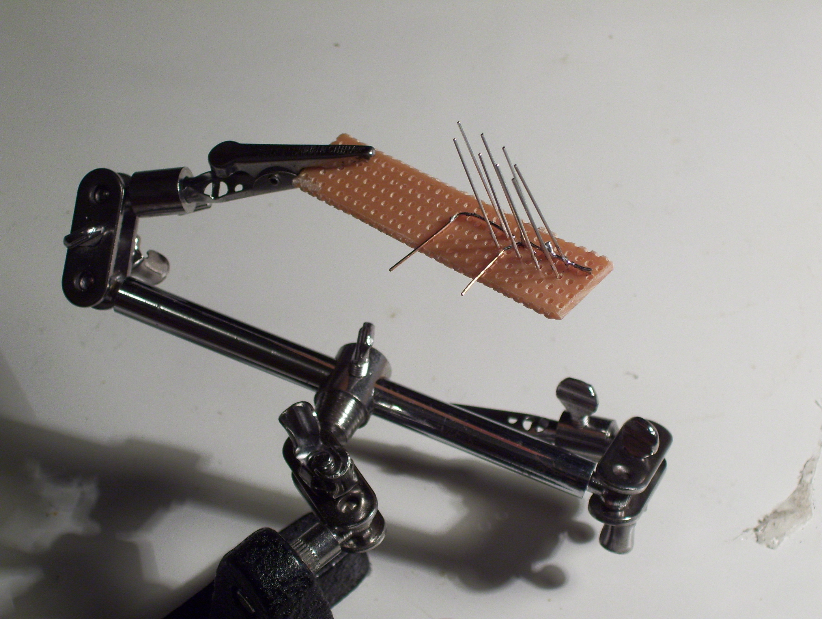
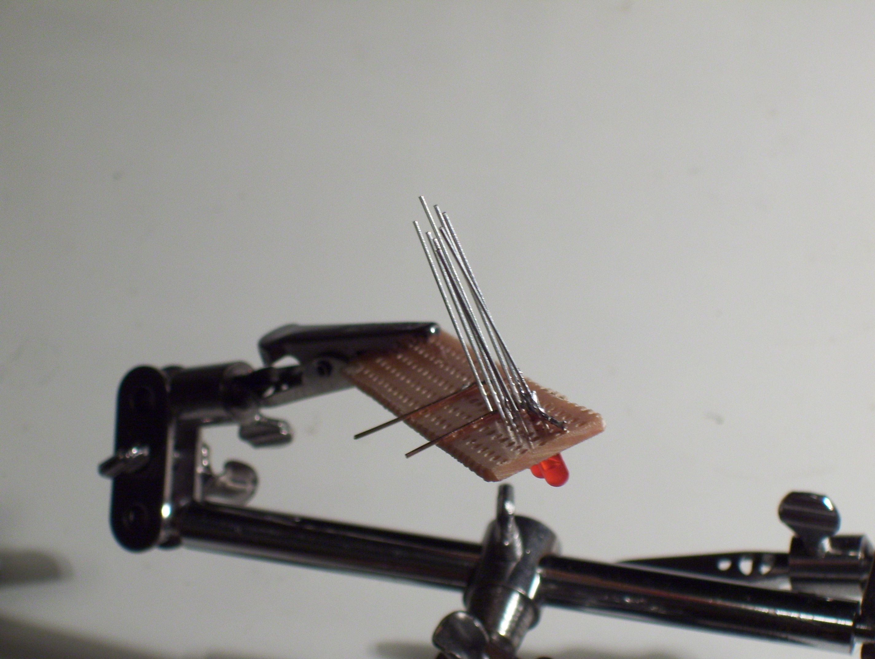
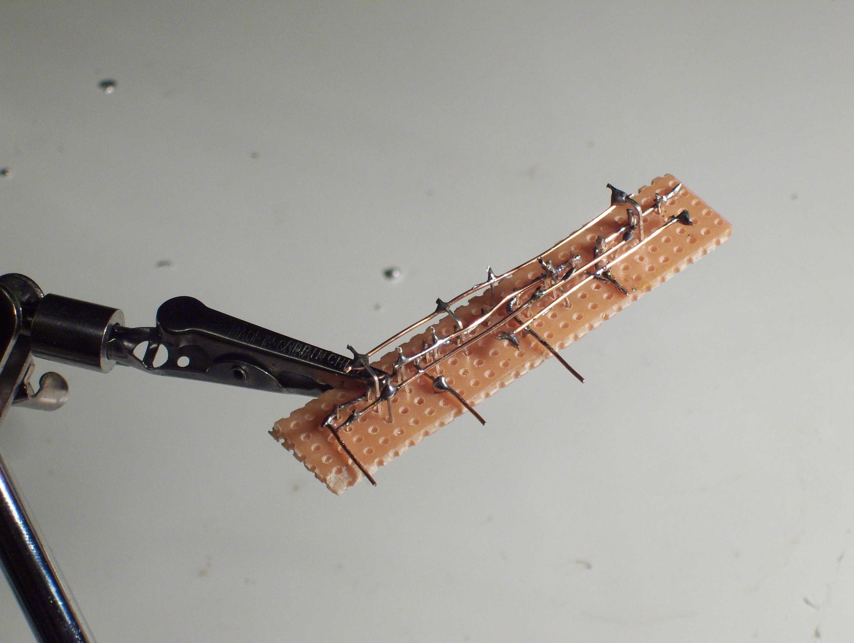
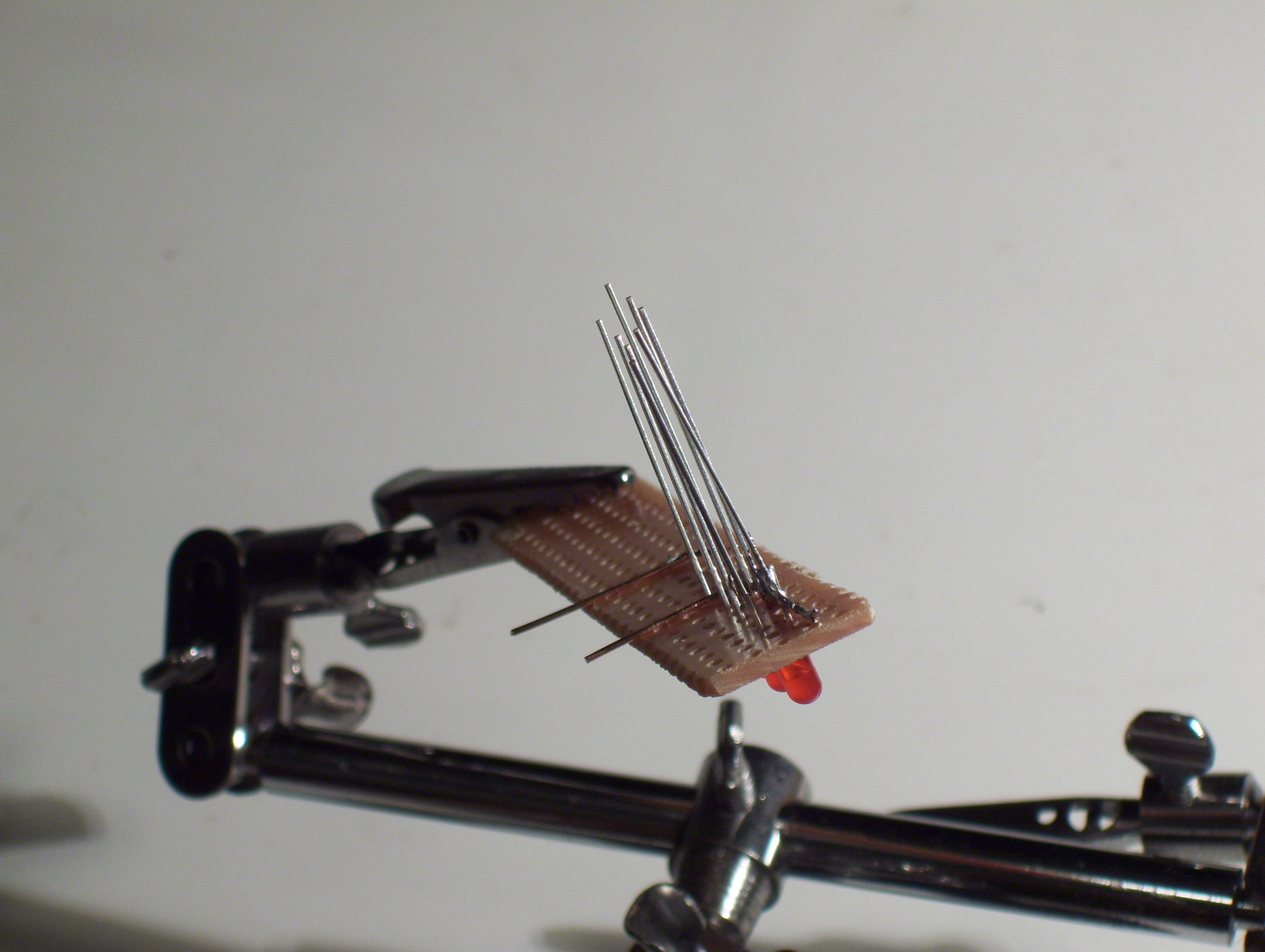
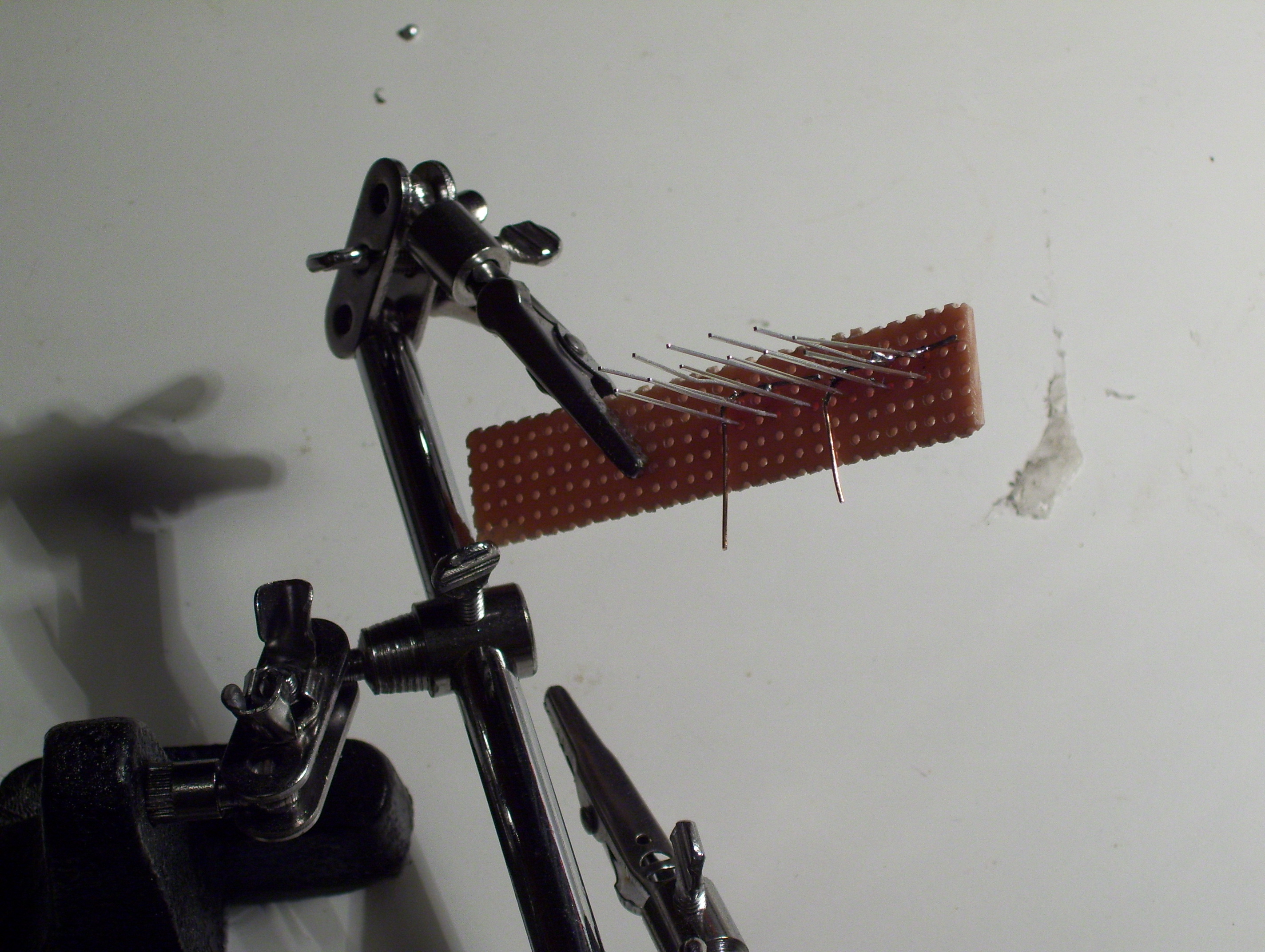
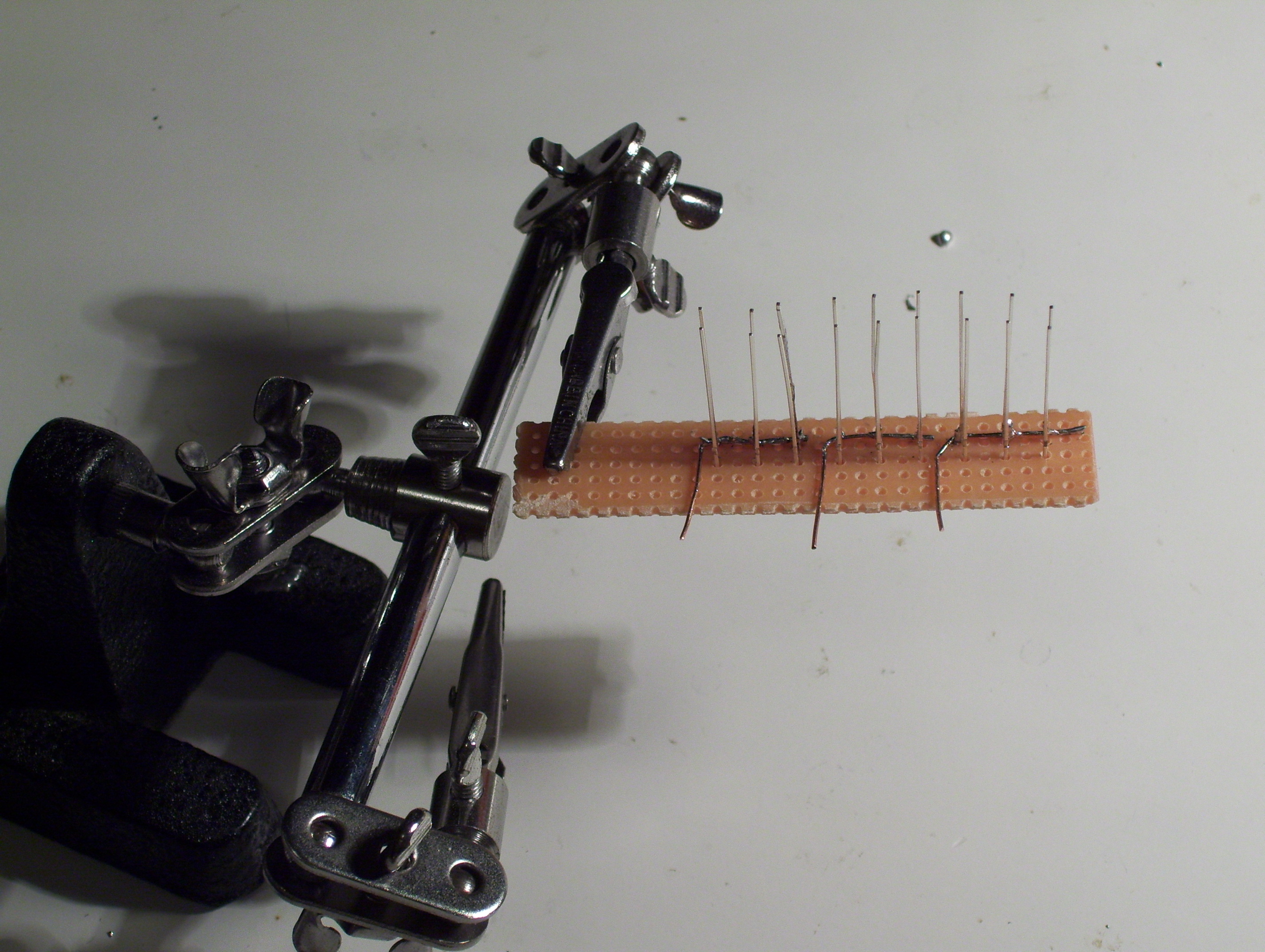
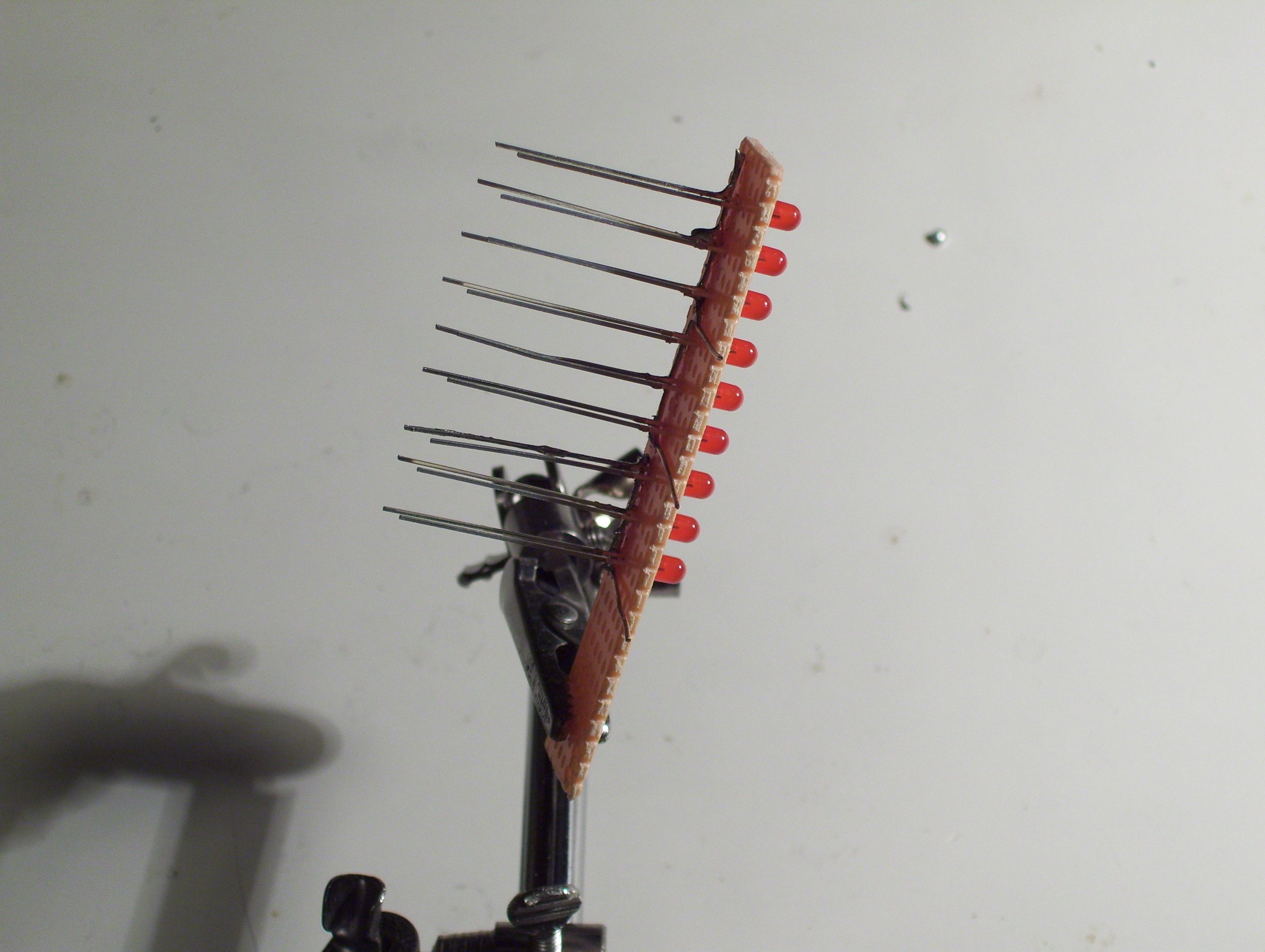
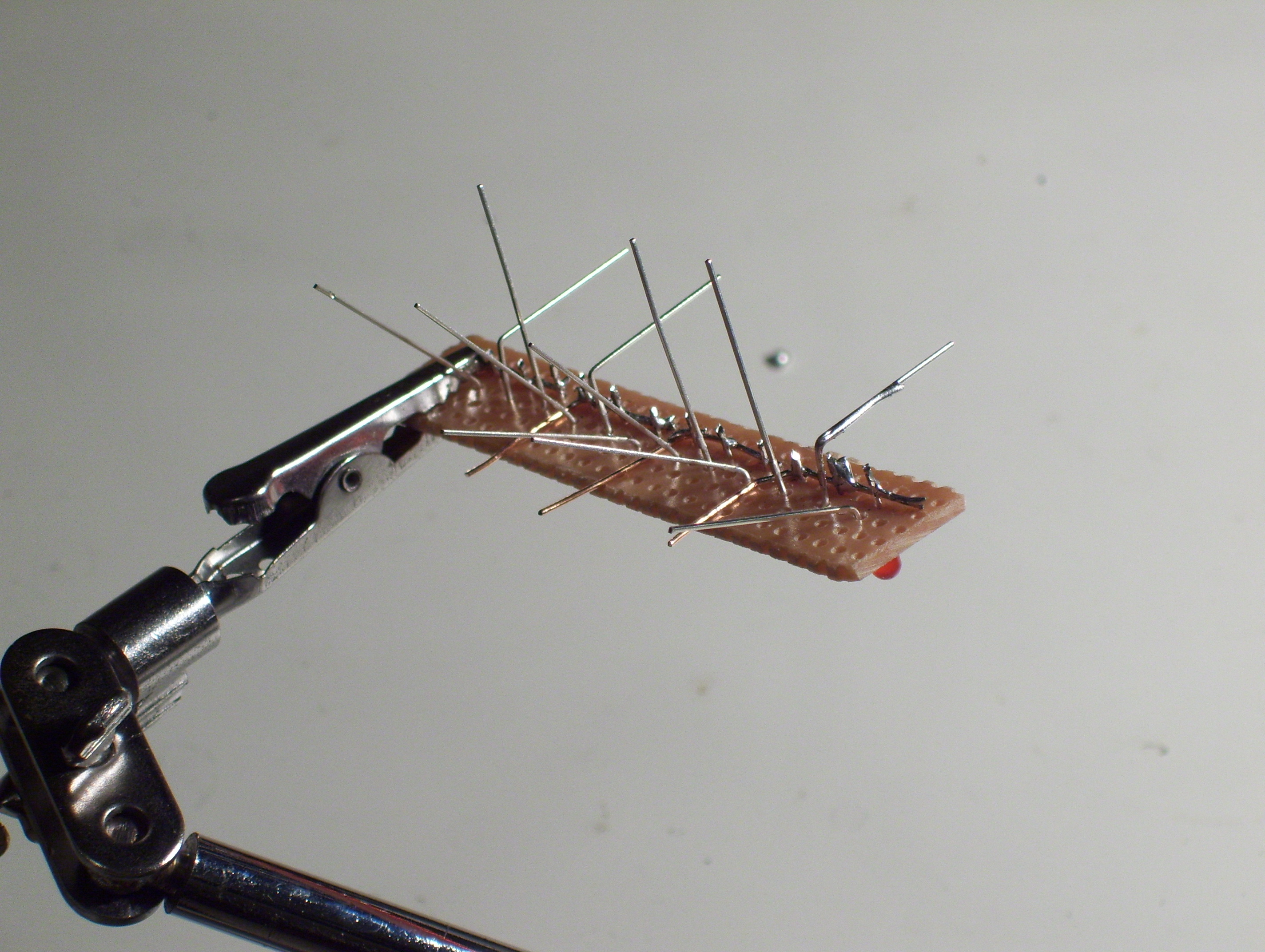
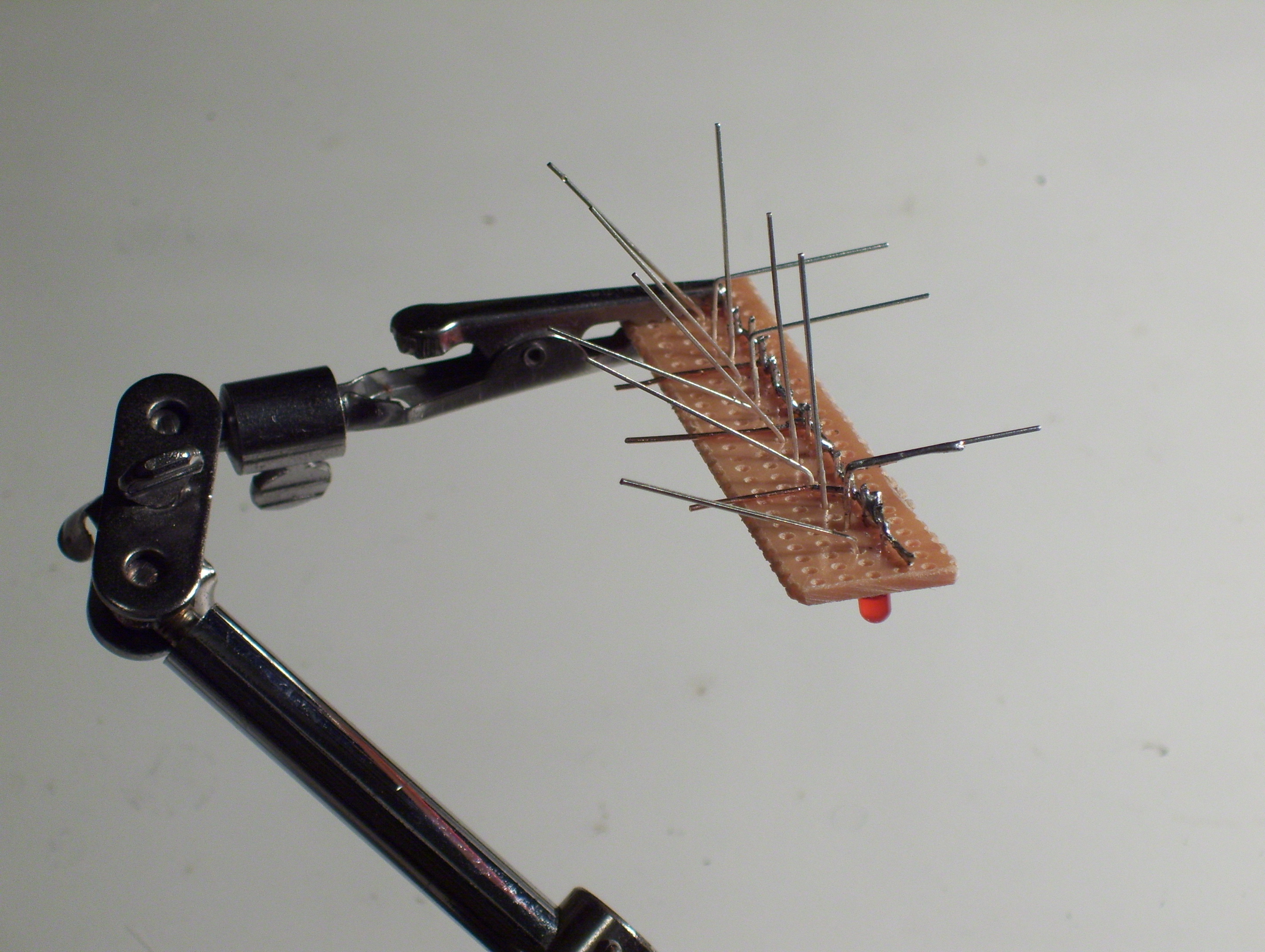
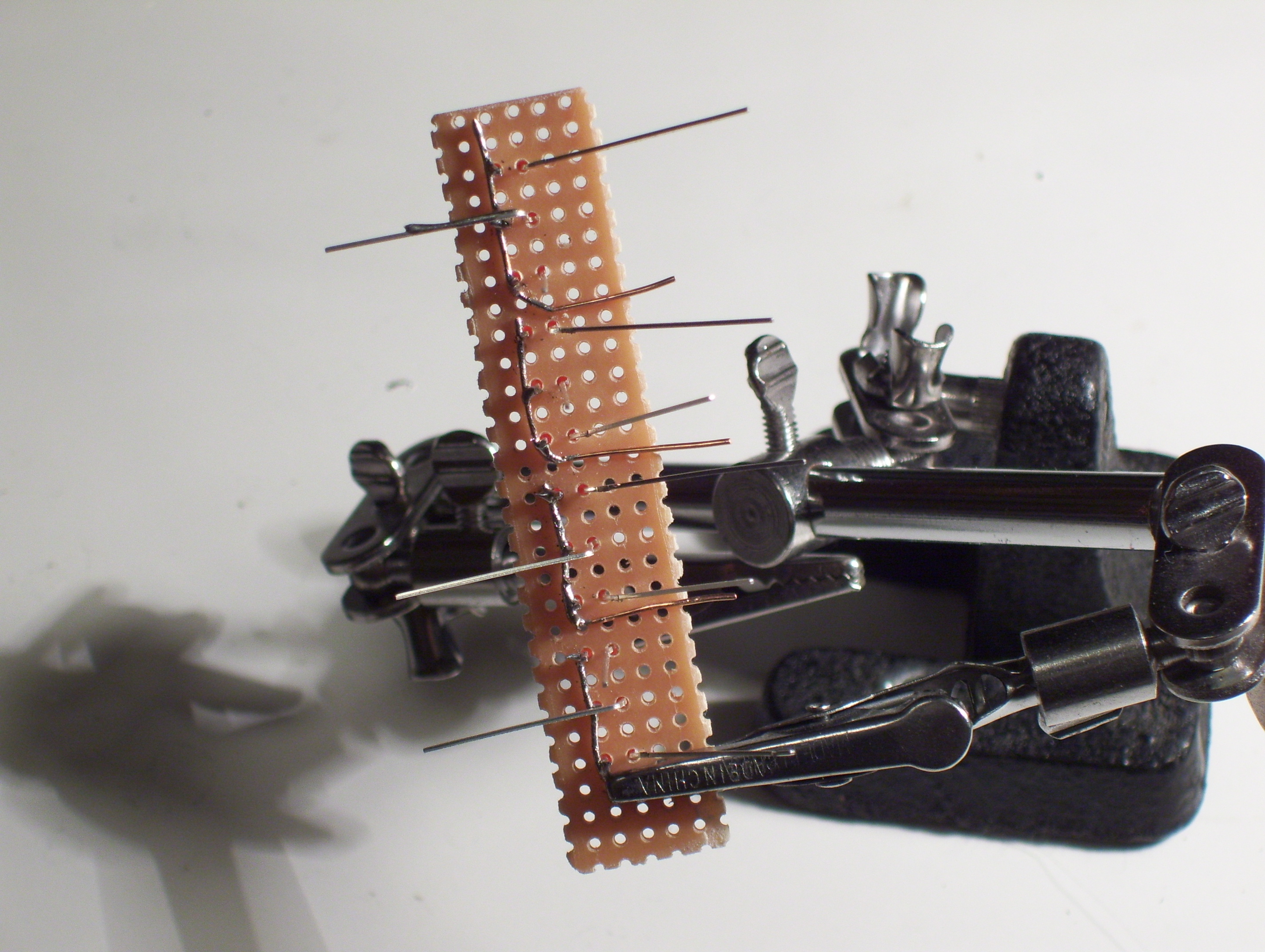
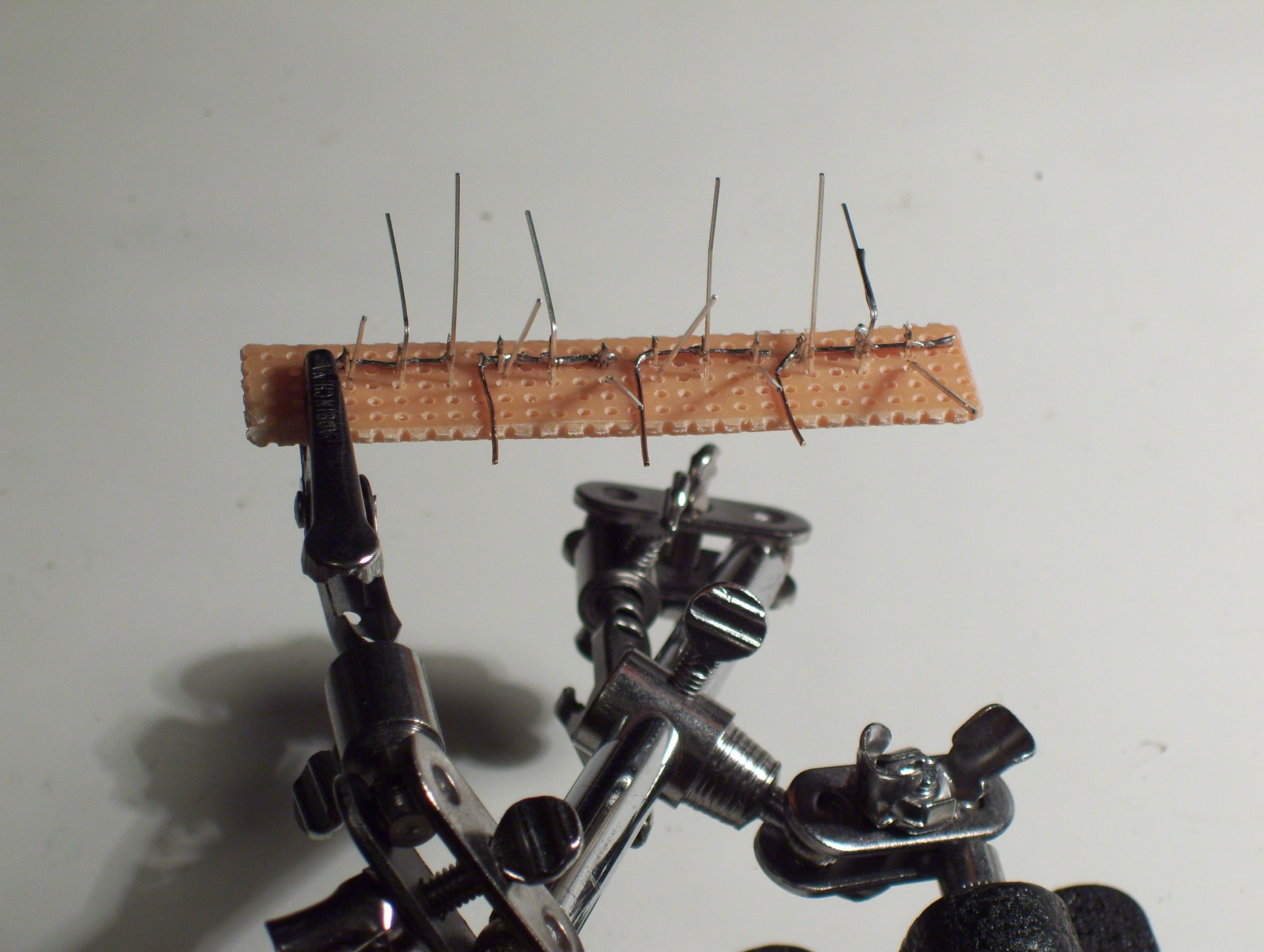
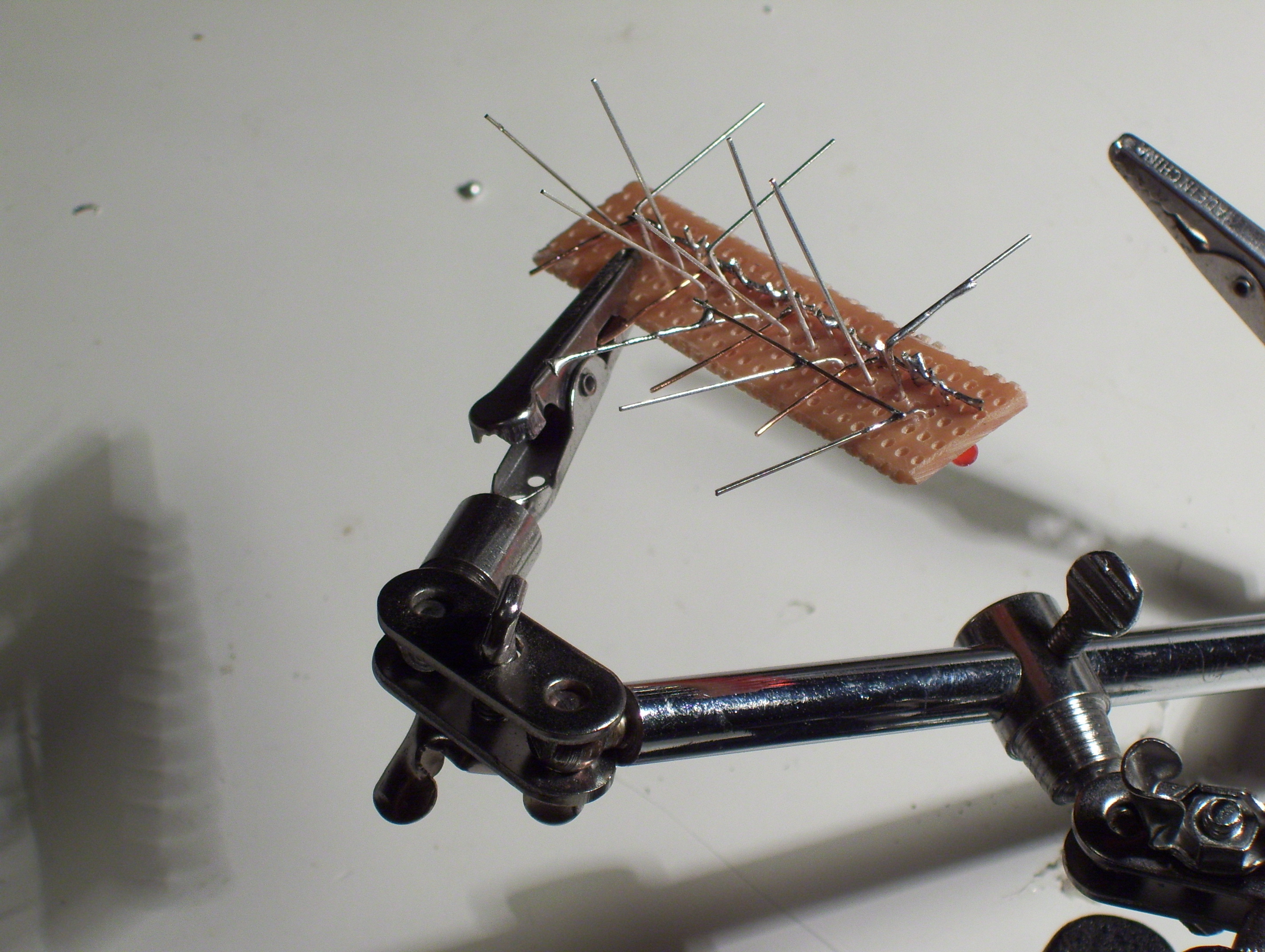
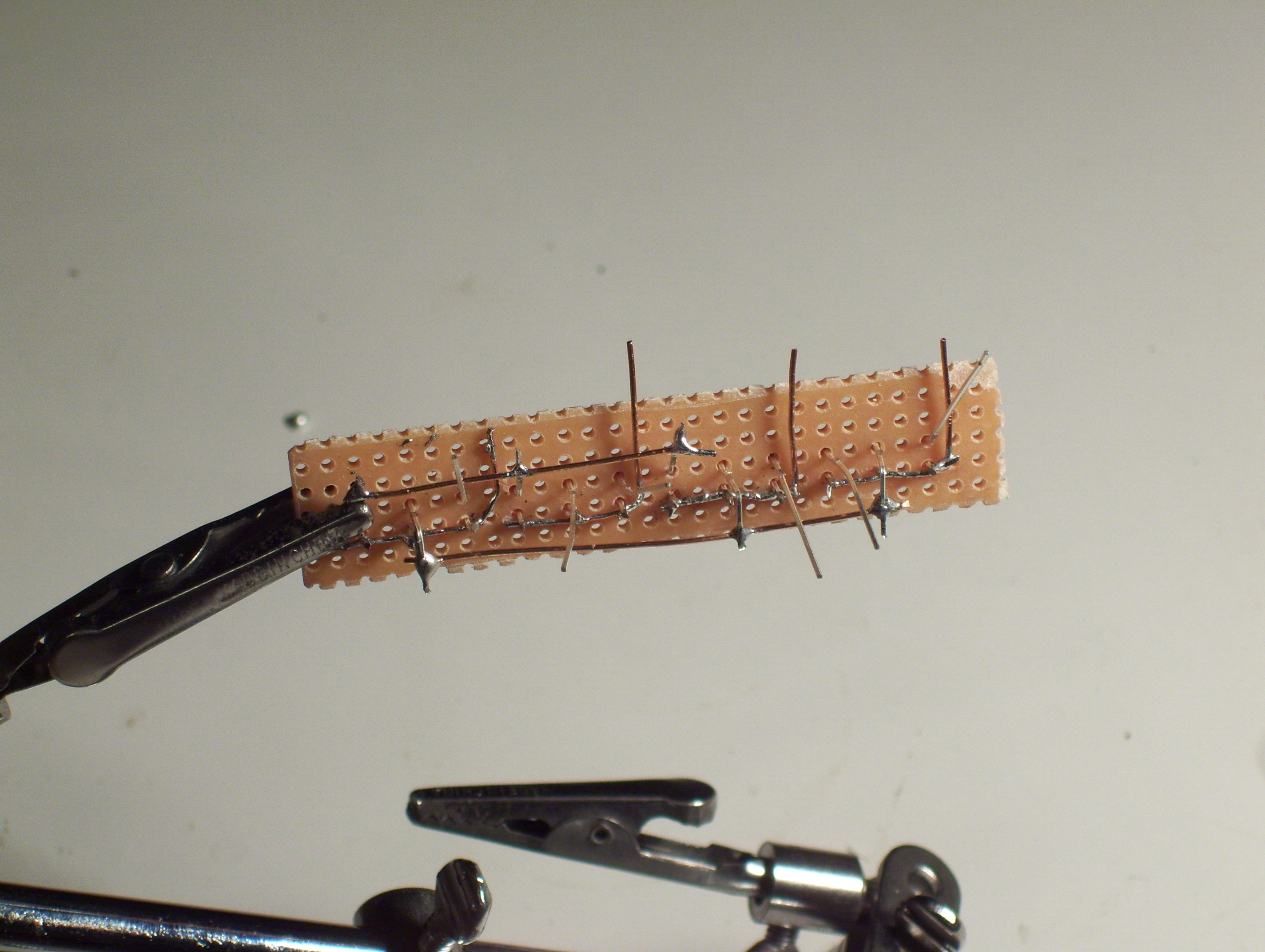
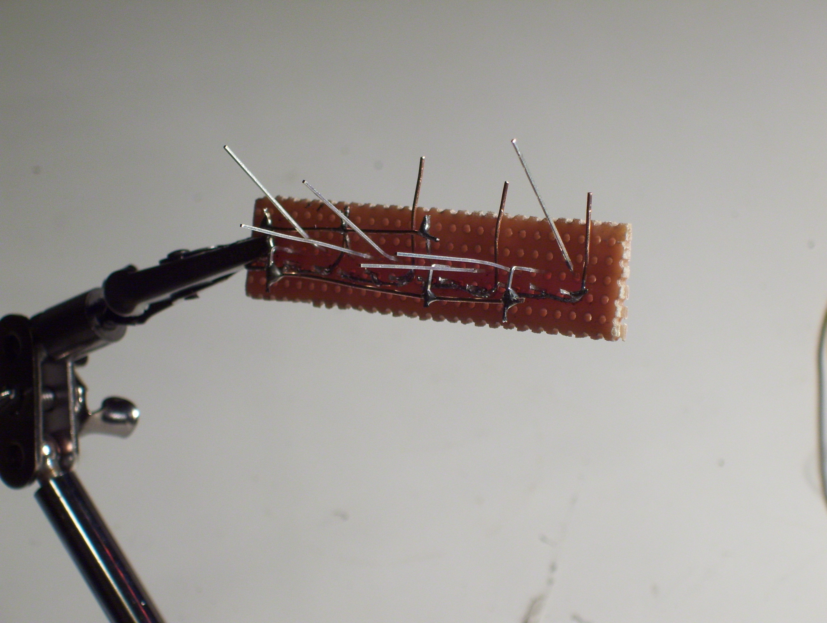
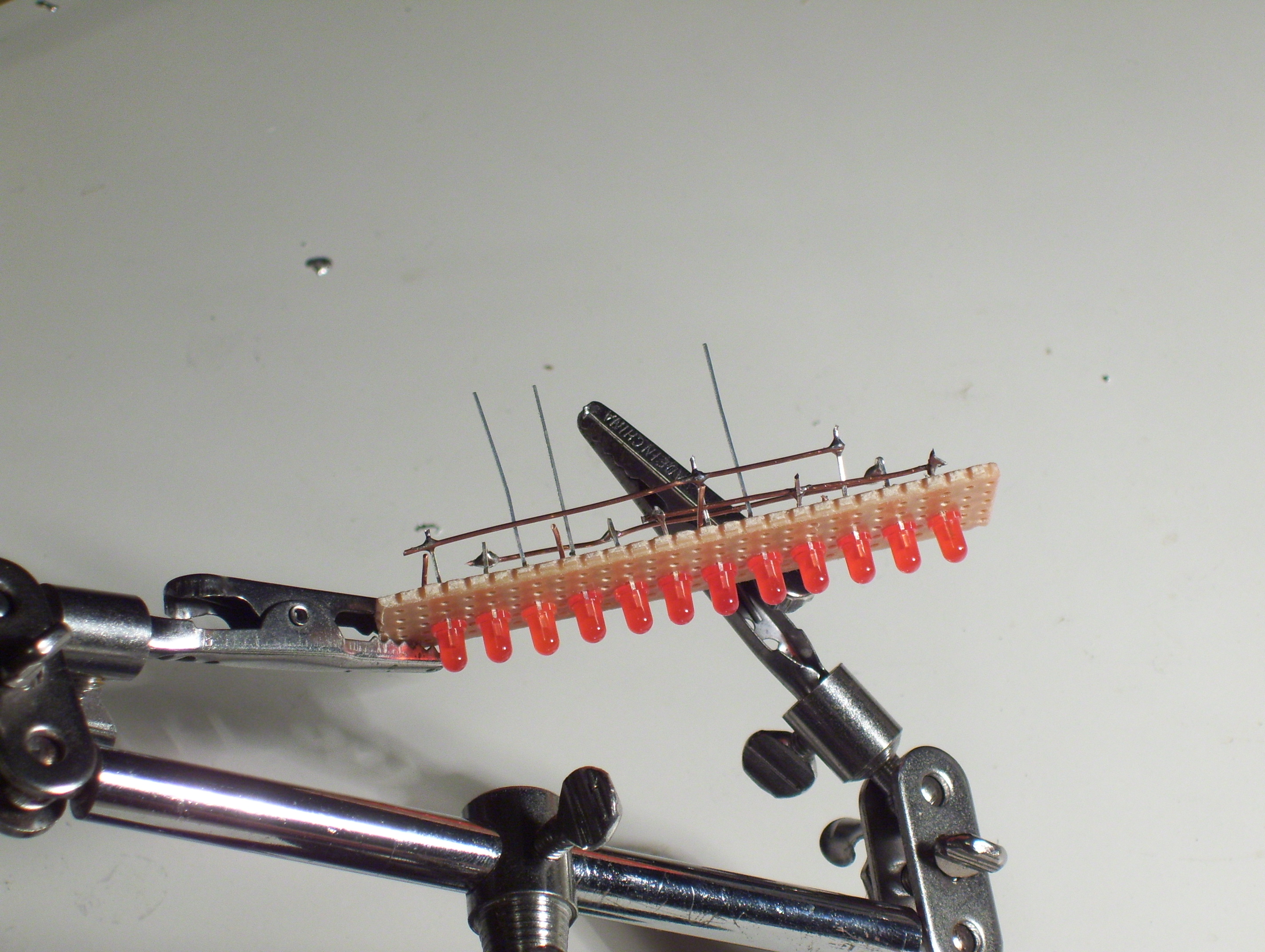
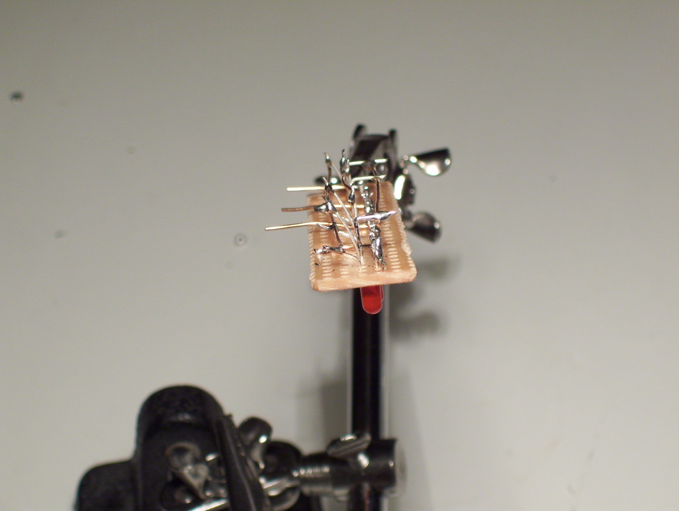
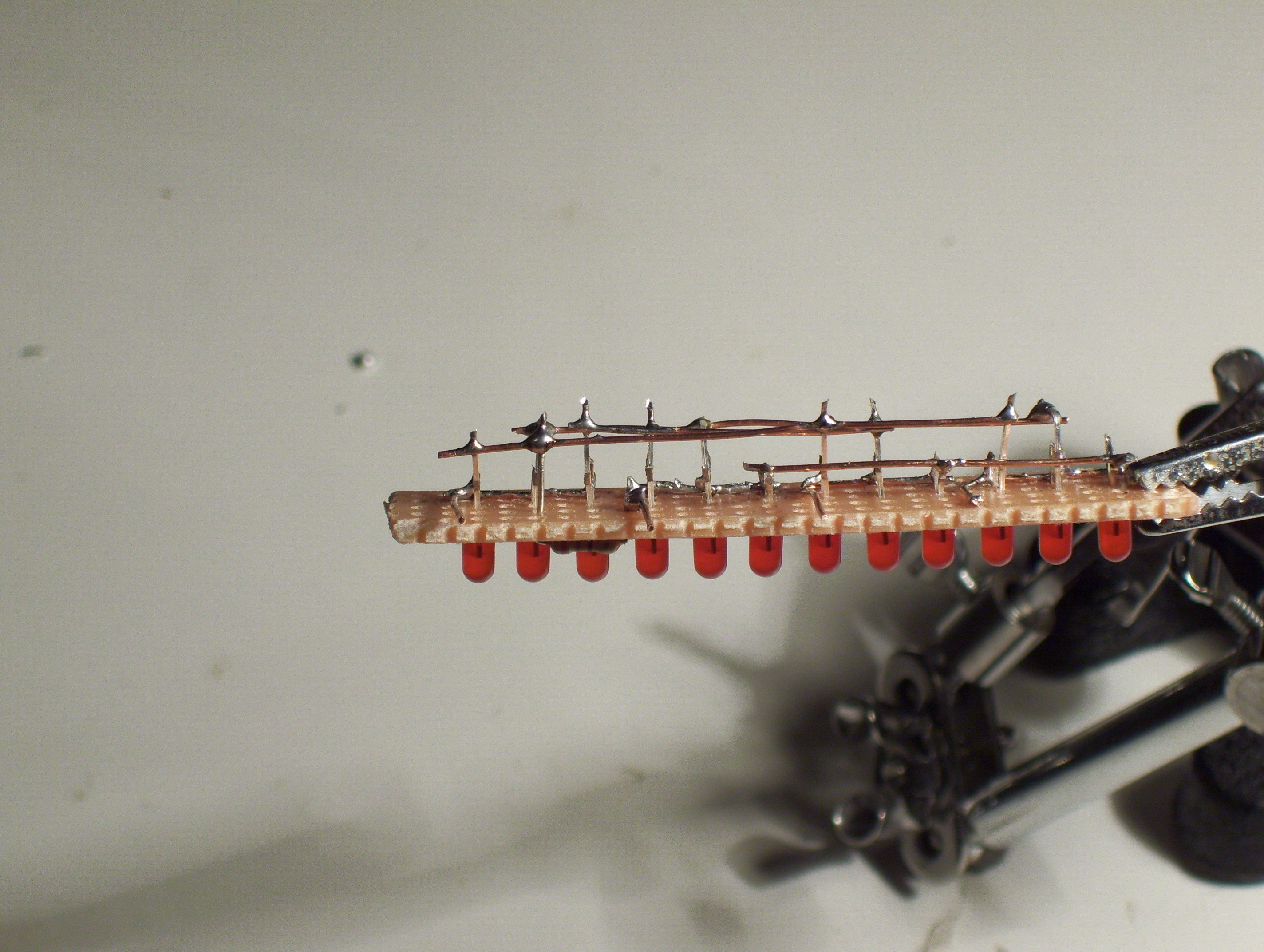
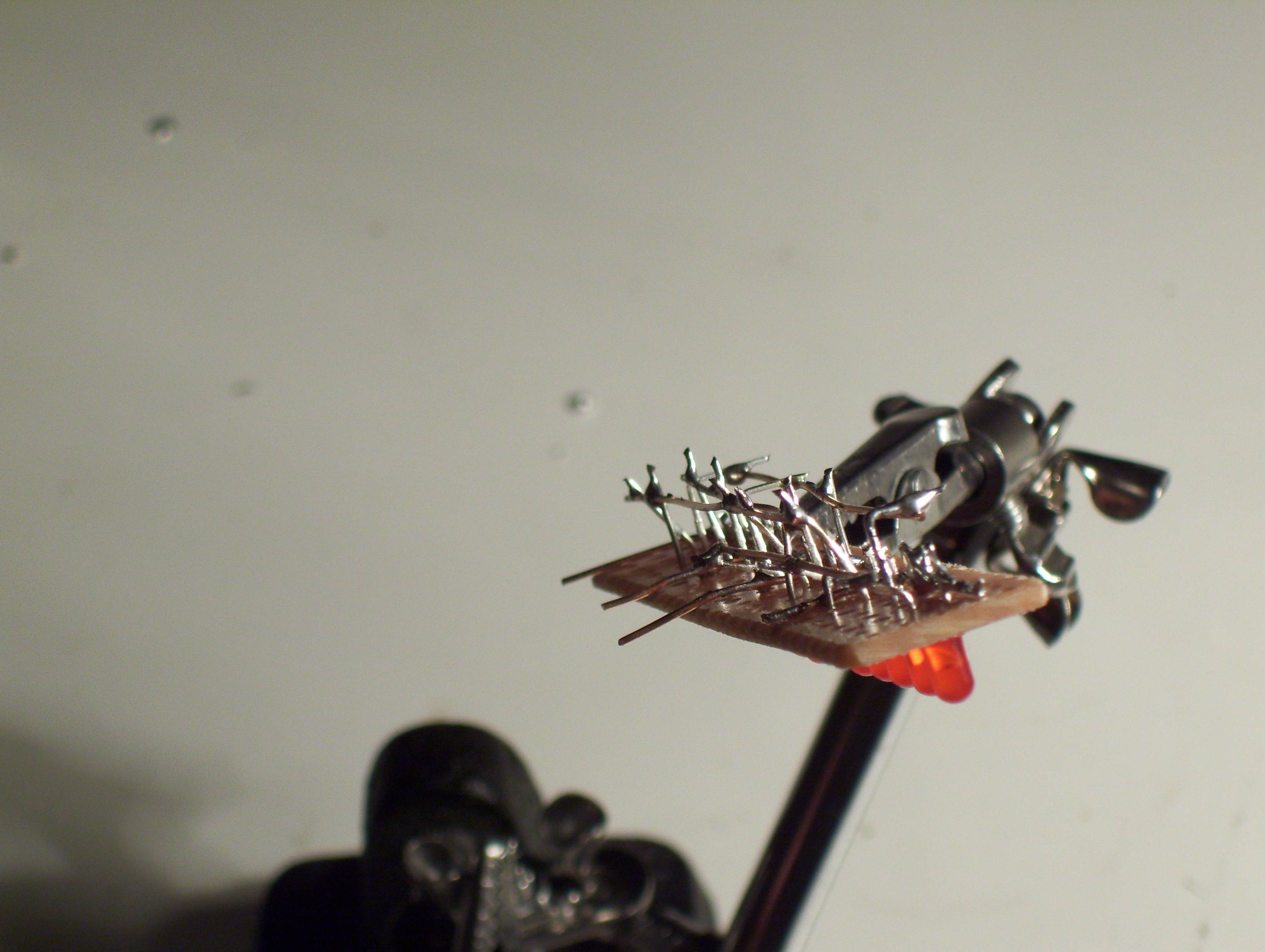
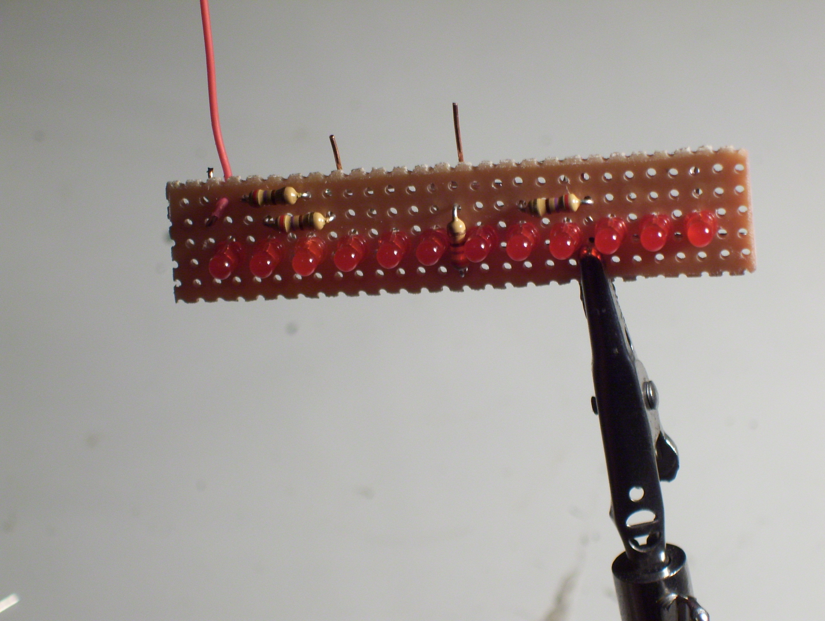
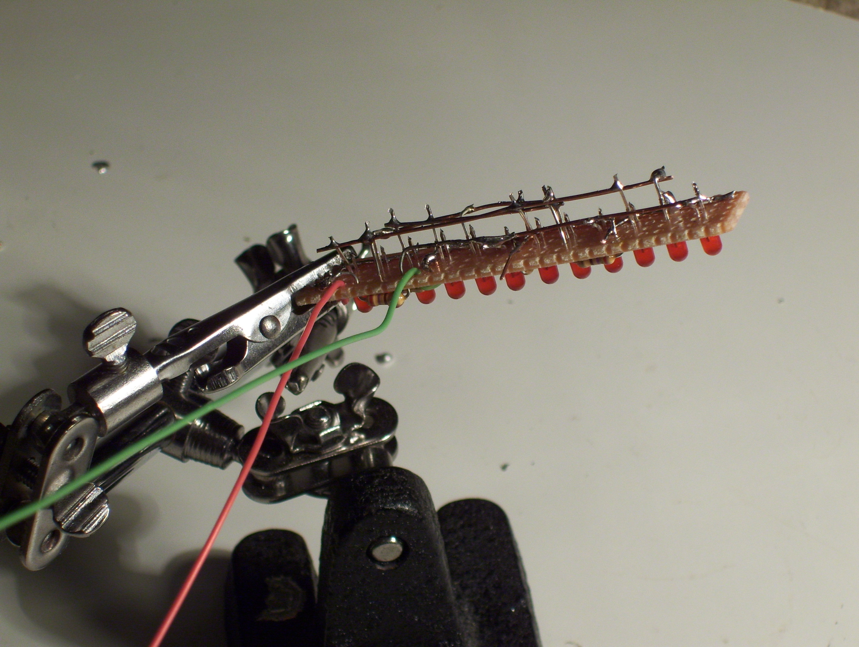
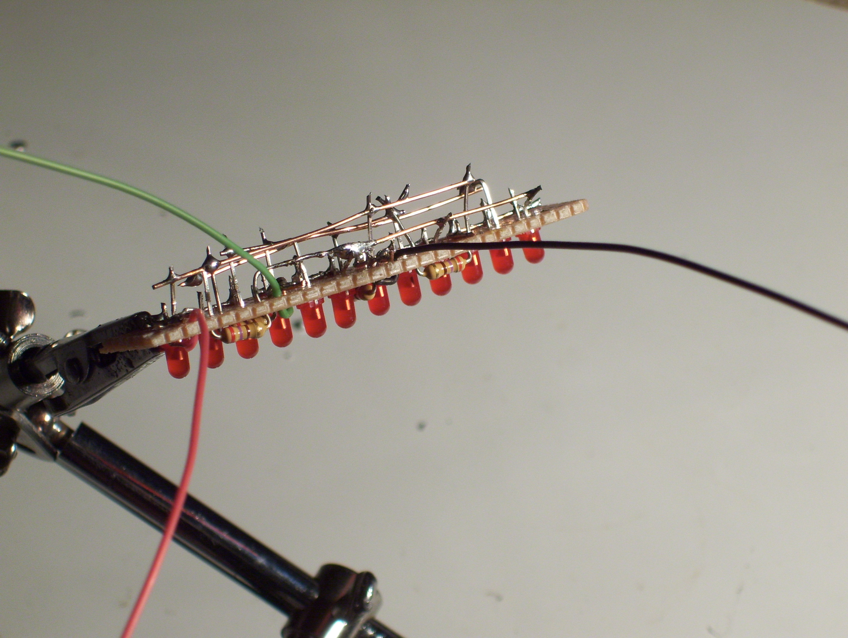
Well, I'm not sure if I when a little overboard with the pictures, But here's the rest of the pictures if you need something clarified. If you have any questions feel free to ask them.
Pictures 1-9: Installing the LED's
Pictures 10-13: Bending the cathodes
Pictures 14-18: soldering the cathodes
Pictures 19-20: Installing the resistors
Pictures 21-23: Installing the control wires
Pictures 1-9: Installing the LED's
Pictures 10-13: Bending the cathodes
Pictures 14-18: soldering the cathodes
Pictures 19-20: Installing the resistors
Pictures 21-23: Installing the control wires