Carvera Makera Back Panel Isolation Install Instructions
by The Props Monster in Workshop > CNC
1876 Views, 4 Favorites, 0 Comments
Carvera Makera Back Panel Isolation Install Instructions

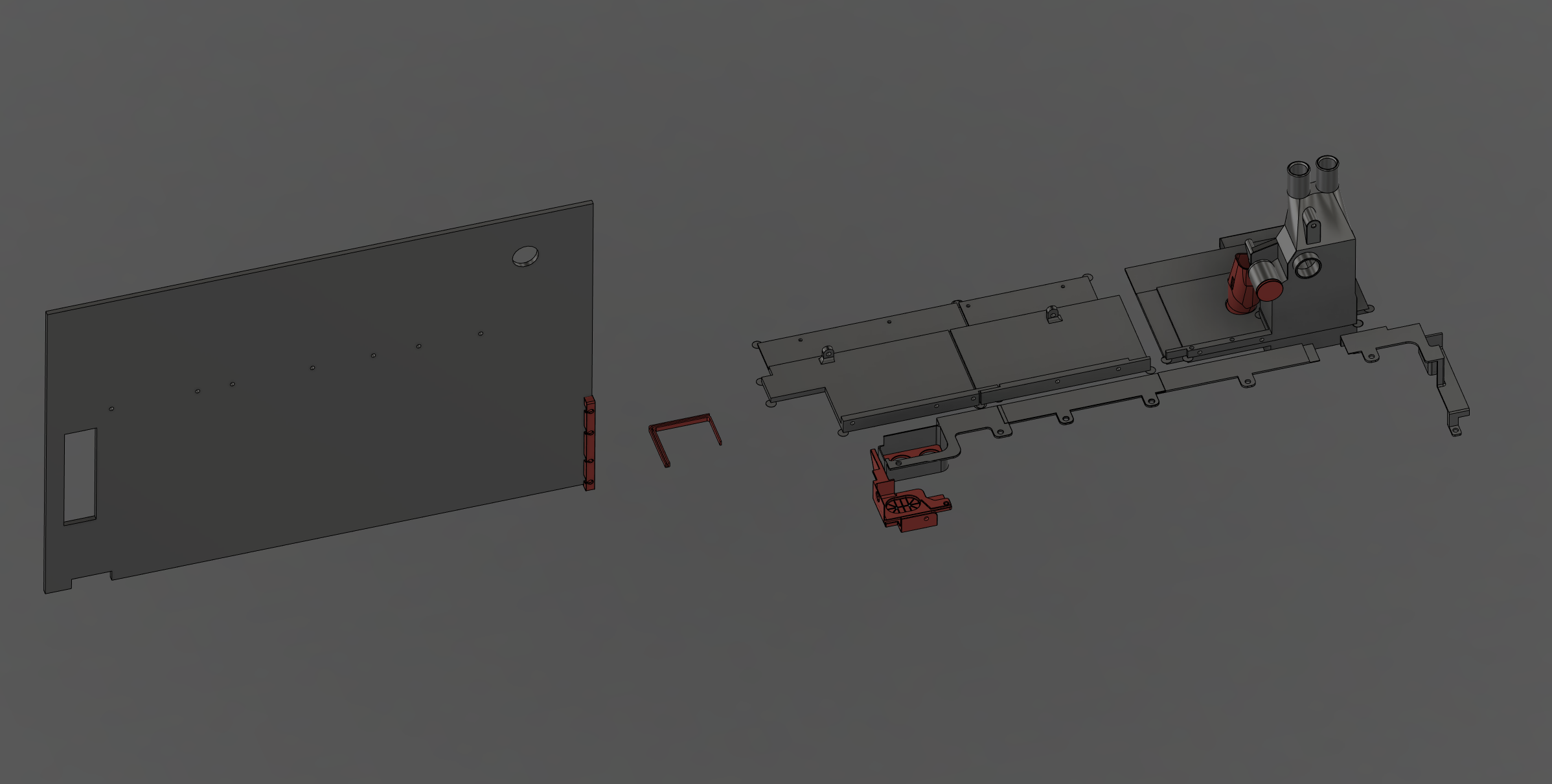

I got tired of chips accumulating in the electronics area of my makera carvera cnc machine. It turns out that the vacuum can pick up chips and blow them directly into the main circuit board. As a result, I designed this set of 3d prints to alleviate those problems.
Files can be found here: https://www.printables.com/model/873426-carvera-back-panel-isolation-3d-prints
During this entire process the machine should be unplugged to prevent any mishaps.
To start, remove the back panel, vacuum hose, and vacuum chamber on the machine. You will need the vacuum removed from the vac chamber.
Supplies
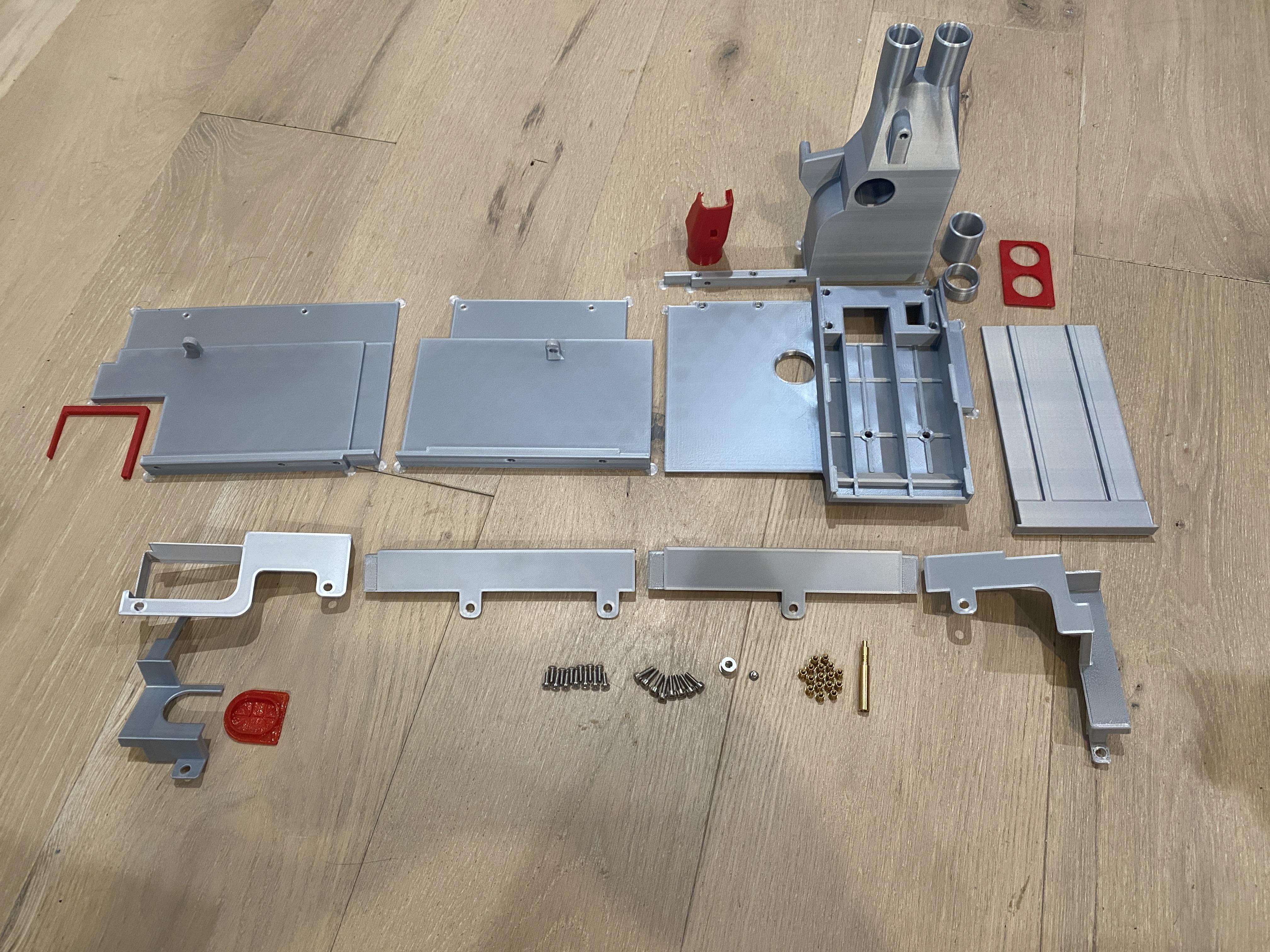
Print all the files from the printables link found in the last step. I used pla for all the parts except those marked specifically as TPU. You will need 2 of the X Axis Cover Screw Plate printed in TPU
You will also need the following hardware or equivalents:
16 m3 heat set inserts https://www.mcmaster.com/catalog/130/4201/97171A310
8 m3 10mm socket head https://www.mcmaster.com/catalog/130/3558/91292A113
13 m3 button head screw https://www.mcmaster.com/catalog/92095A182
1 m3 countersunk screw https://www.mcmaster.com/catalog/130/3473/91263A821
6 m3 washer https://www.mcmaster.com/93475A230/
Clean Off Mouse Ears

Several of the parts will have mouse ears on them to help print stability. Clean them off with a razor blade/some files.
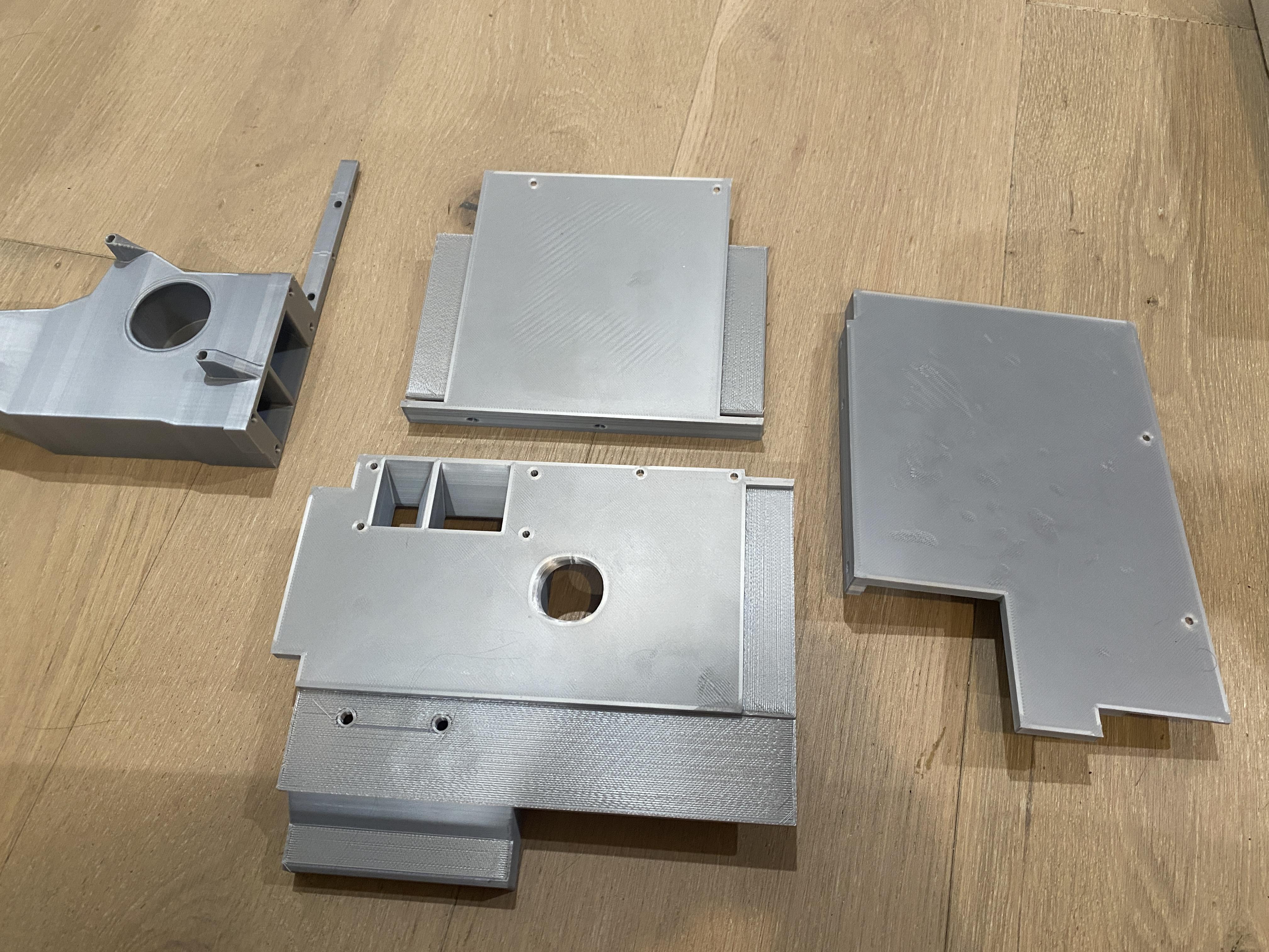
Install Heat Set Inserts
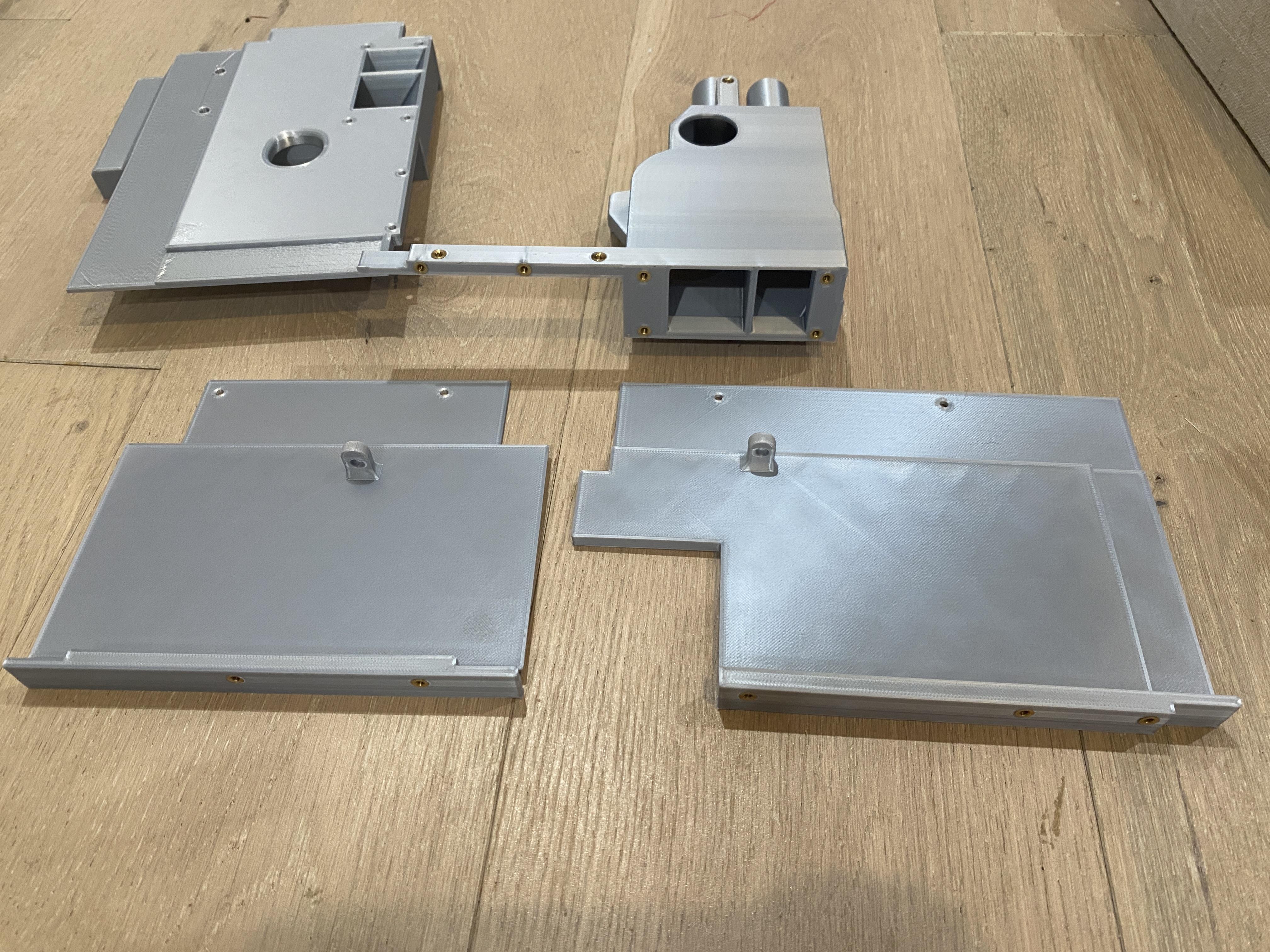
ElectronicsProtectionPanelPowerSide, ElectronicsProtectionPaneCenter, and Vac Chamber Top all require heat set inserts installed.
The ElectronicsProtectionPanels require heat set inserts in the short raised section. The two taller single hole pieces should not get heat set inserts
The Vac Chamber top requires heat set inserts in all visible 4mm holes.
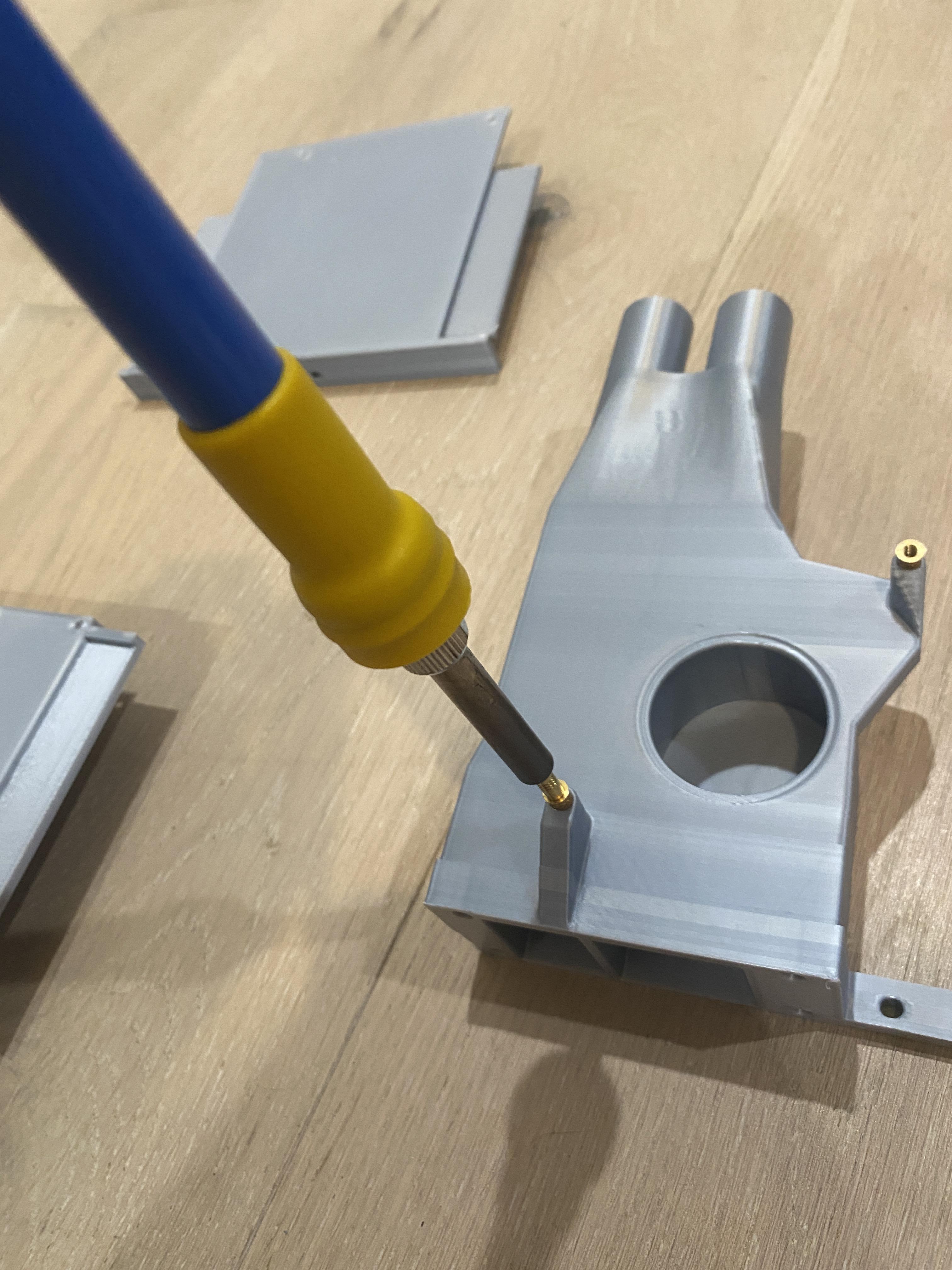
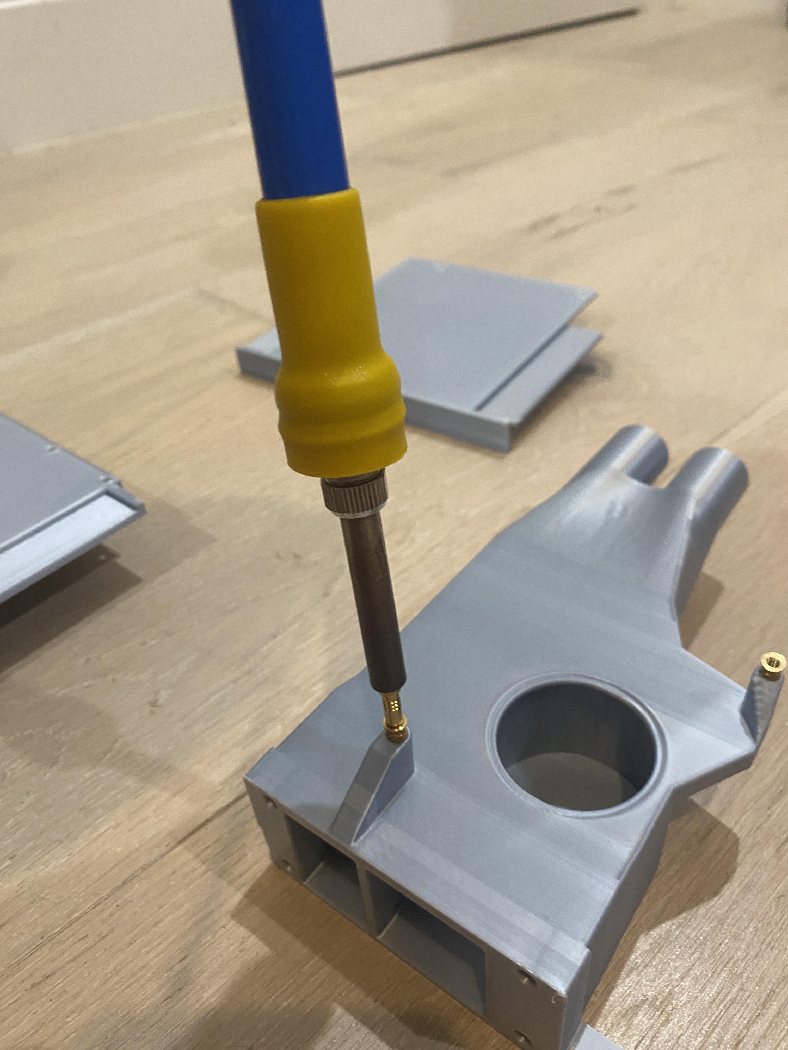
All heat set inserts should be flush or just under the surface of the part.
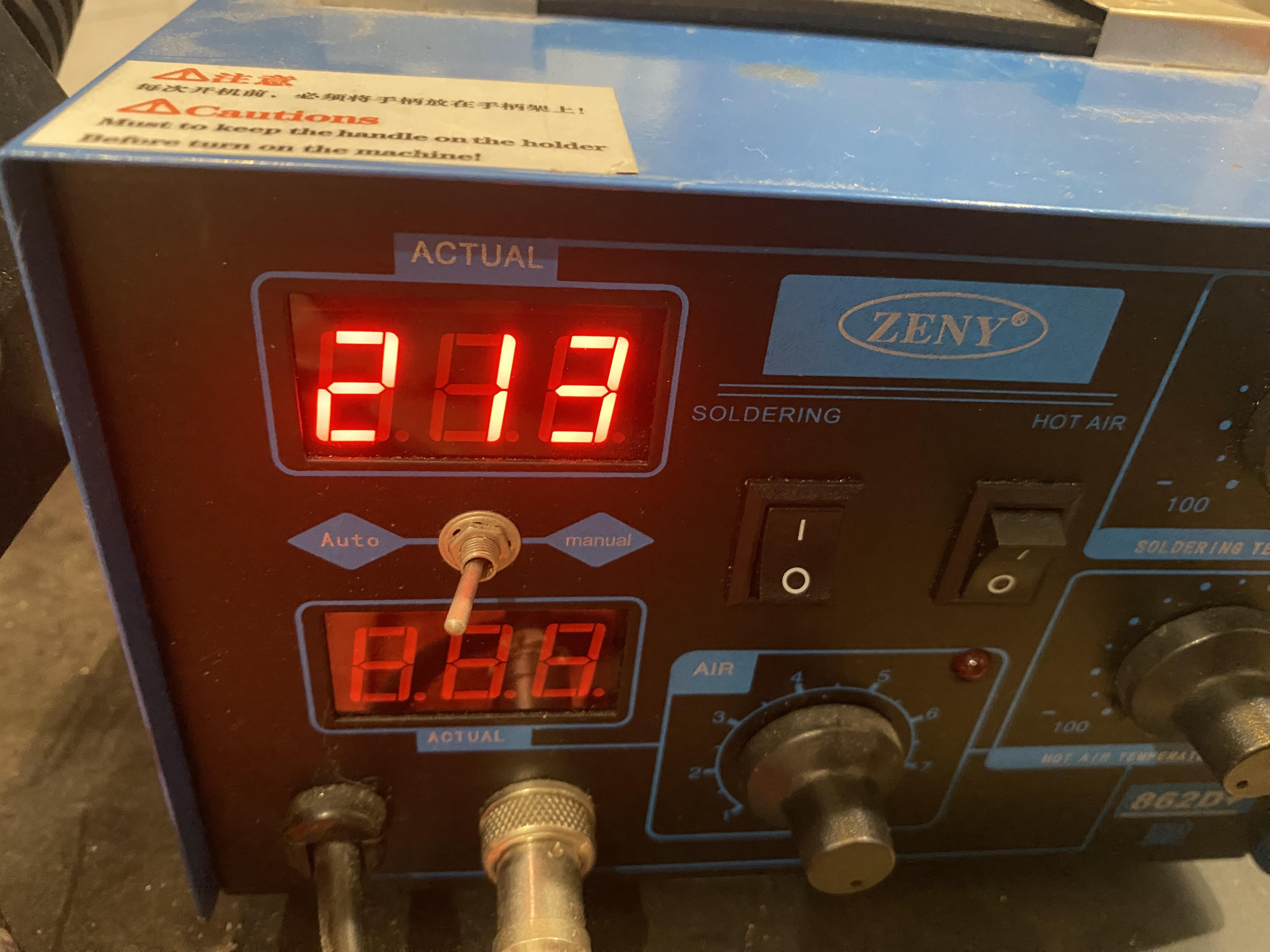
I use a soldering iron at 210-215 degrees Celsius and a heat set insert tip. Place the insert into the hole and press the soldering iron into the insert with gentle pressure. Once fully heated the insert will easily sink into the part, too much pressure could crack the part.
Assemble Vacuum Chamber
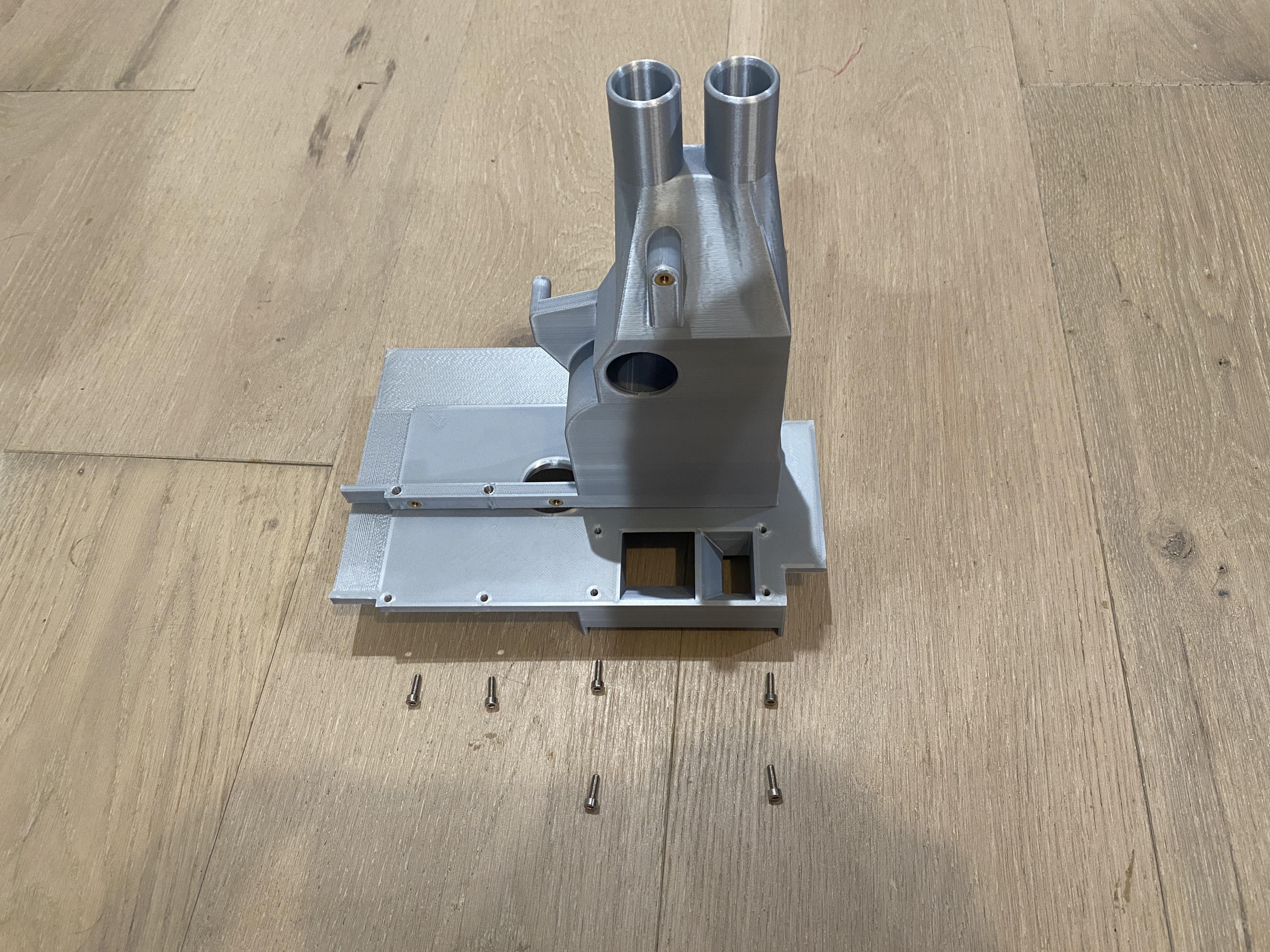
The two vac chamber pieces fit together with 6 10mm long M3 cap head bolts. On earlier versions of the design the top and bottom required 4 20mm M3 cap head bolts.
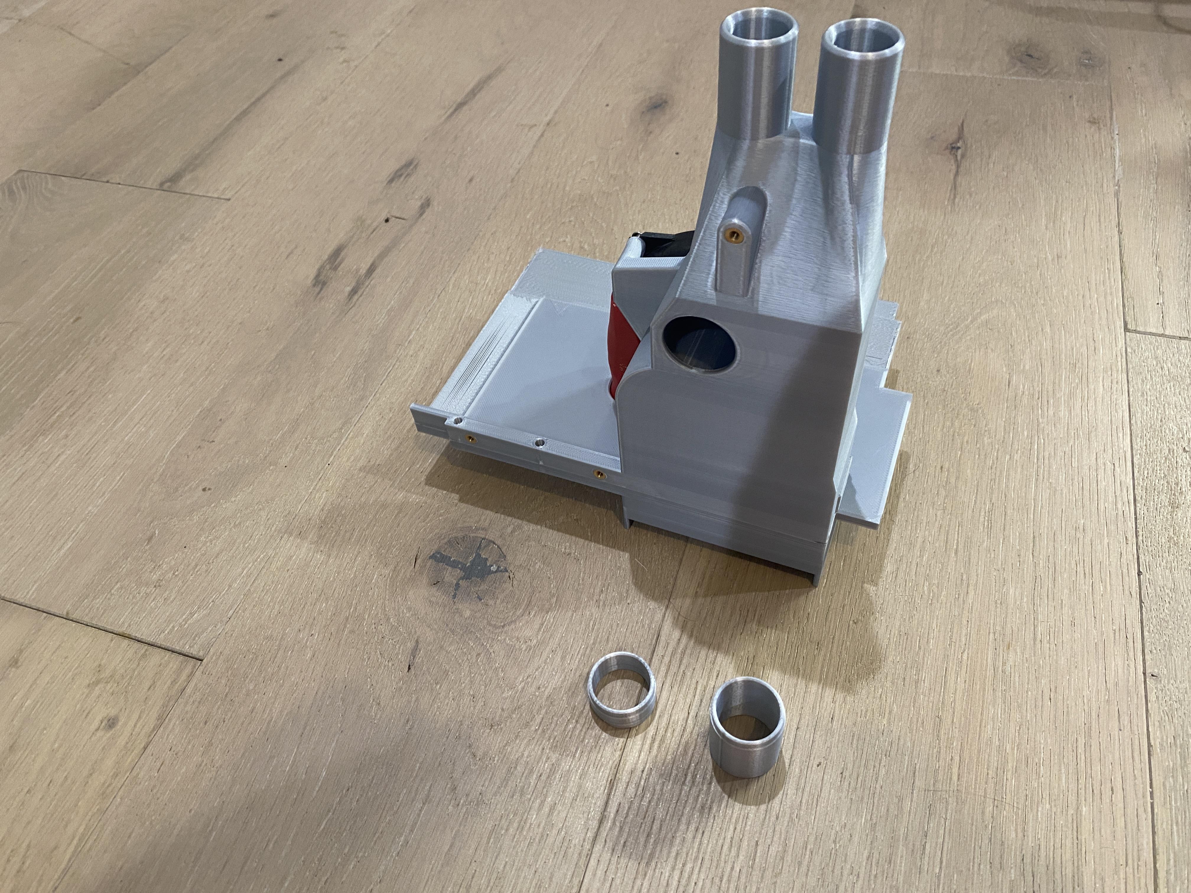
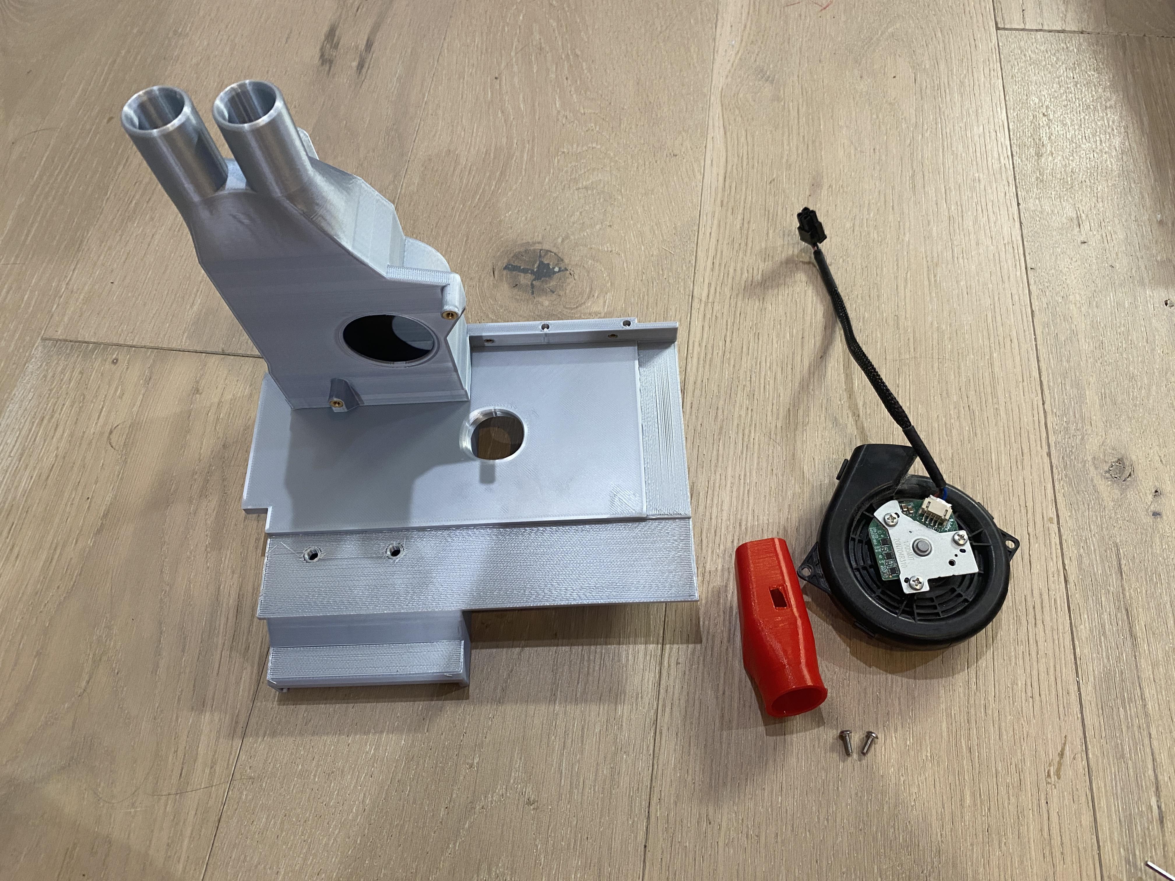
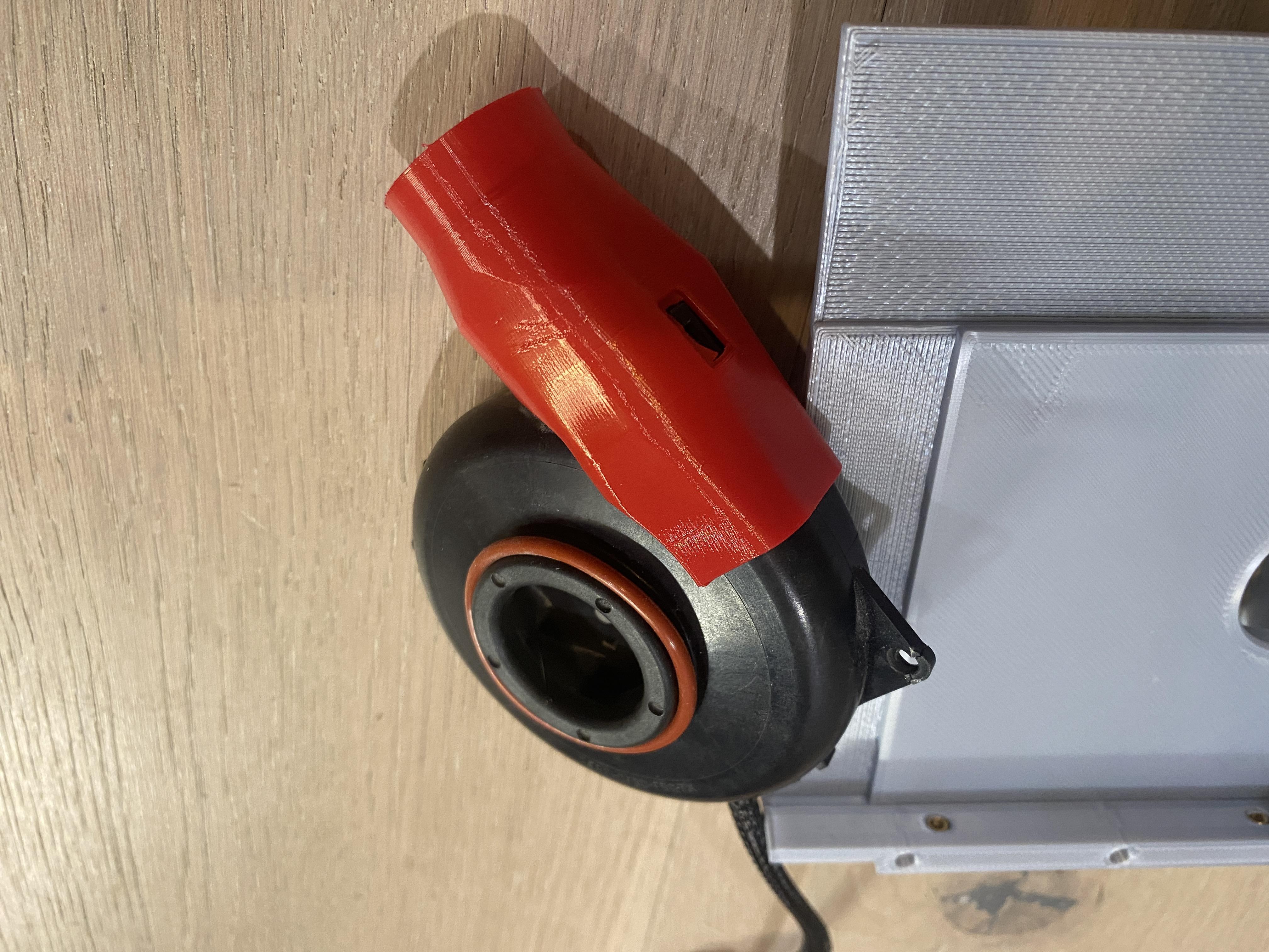
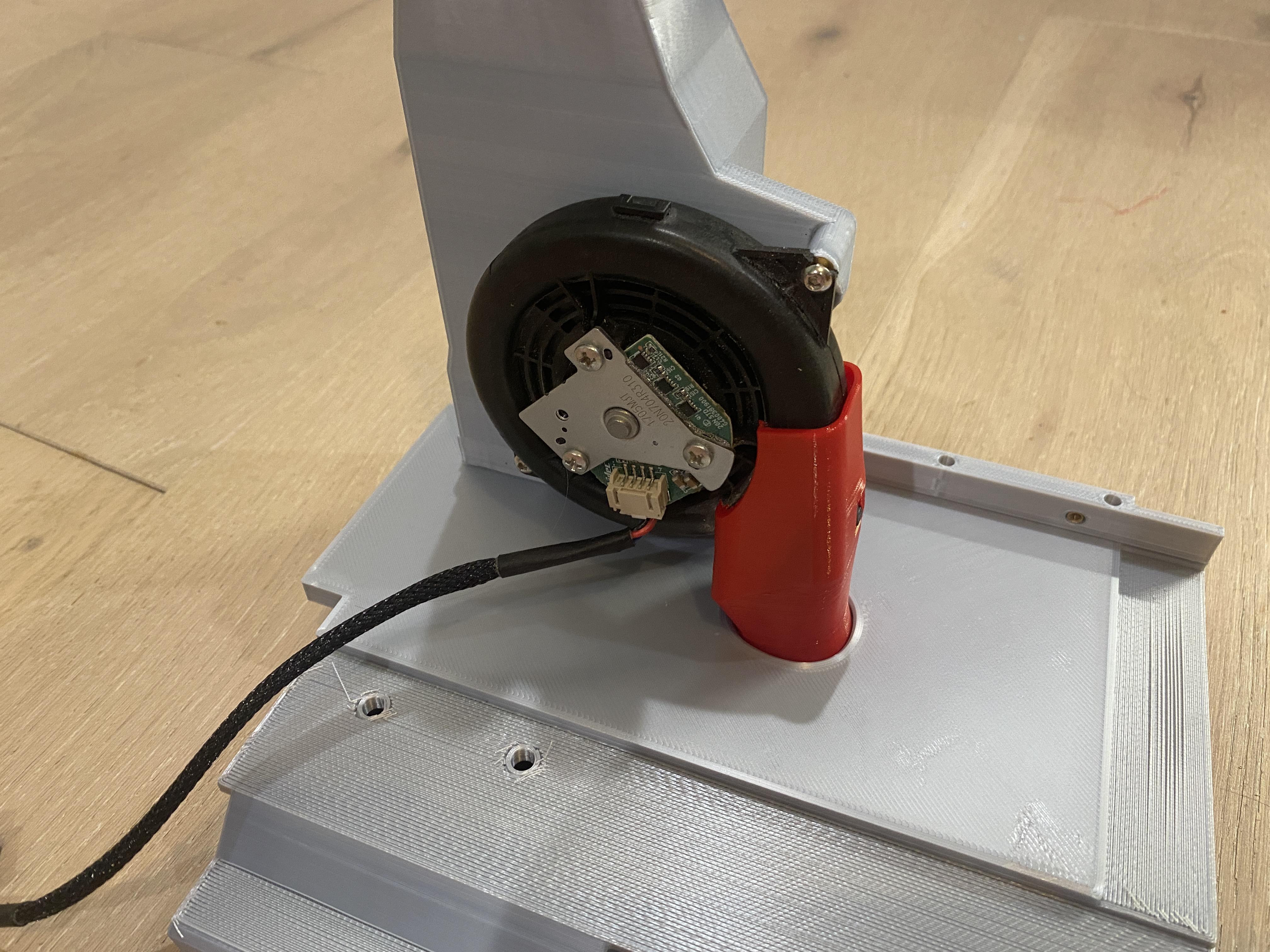
Once the pieces are firmly attached start work on the vacuum. The tpu piece fits over the end of the vacuum and there is a notch cutout for a locking feature on the vacuum. It then installs on the back of the vac chamber top with 2 of the M3 cap head screws. The tpu presses through the vac chamber bottom piece and outputs the air back into the build chamber instead of into the circuit board.
There are 2 Outside Inlet designs on the printables page, the short one replicates the existing machine vac chamber, the longer one gives a bit more surface area to hold onto. One of them should be super glued into the vac chamber hole opposite the vacuum. In these instructions that piece will be visibly missing throughout.
Alternatively, you can use the step or fusion files to design a different attachment to better fit your particular external vacuum.
Wiring Modifications

This step might be optional with the new design of the cable grommet. If you are having difficulty with installing the grommet, come back to this step.
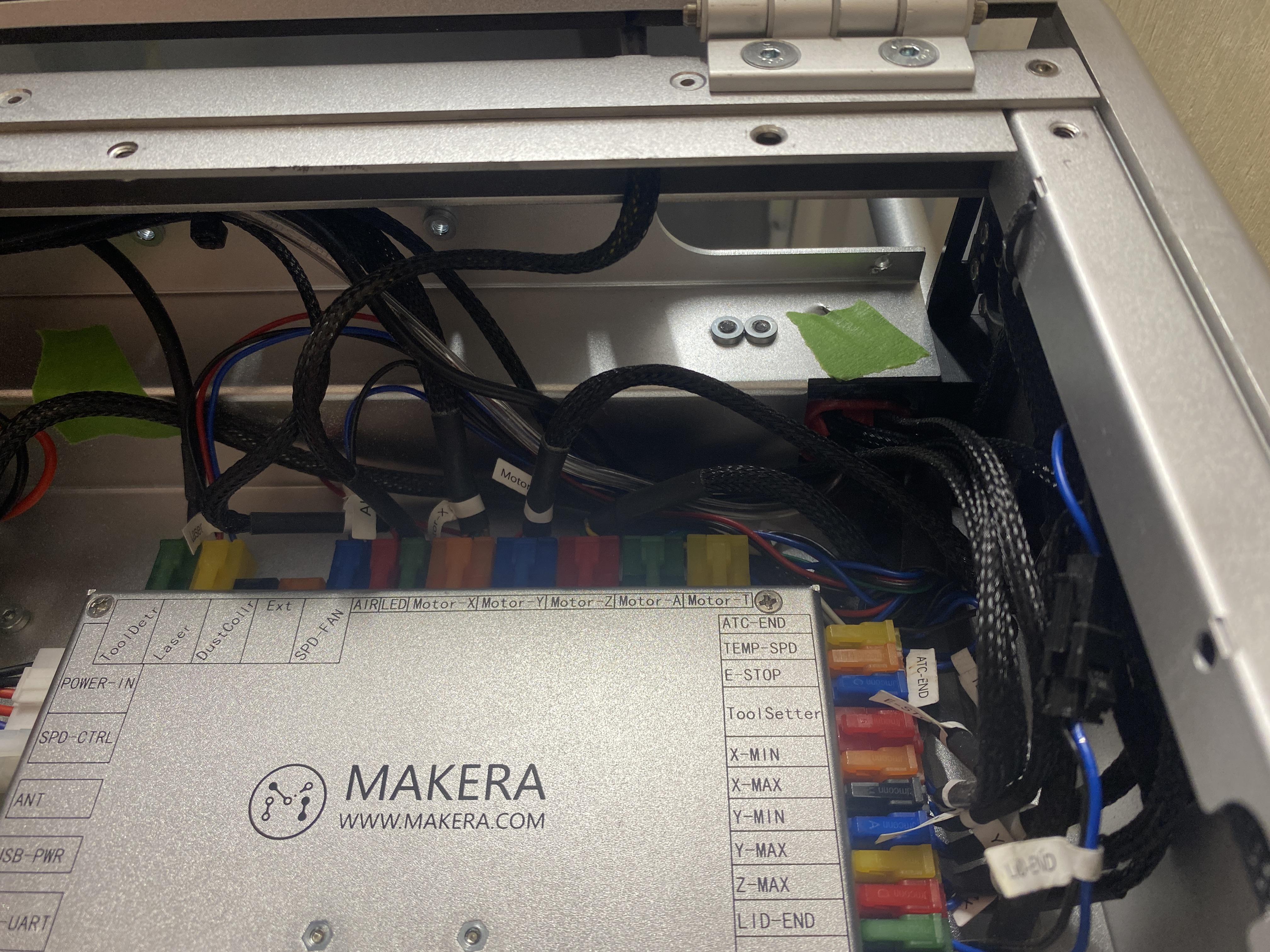
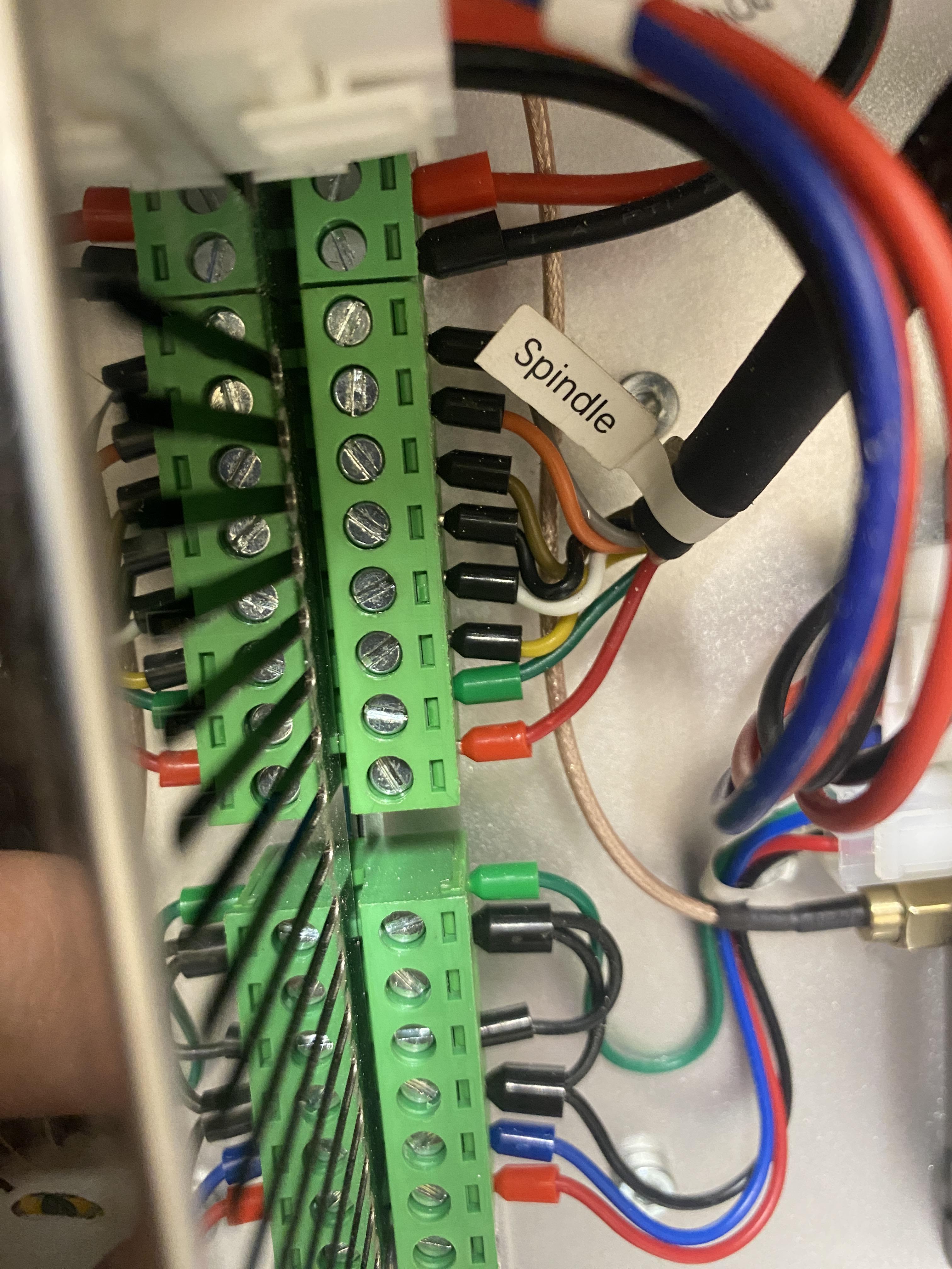
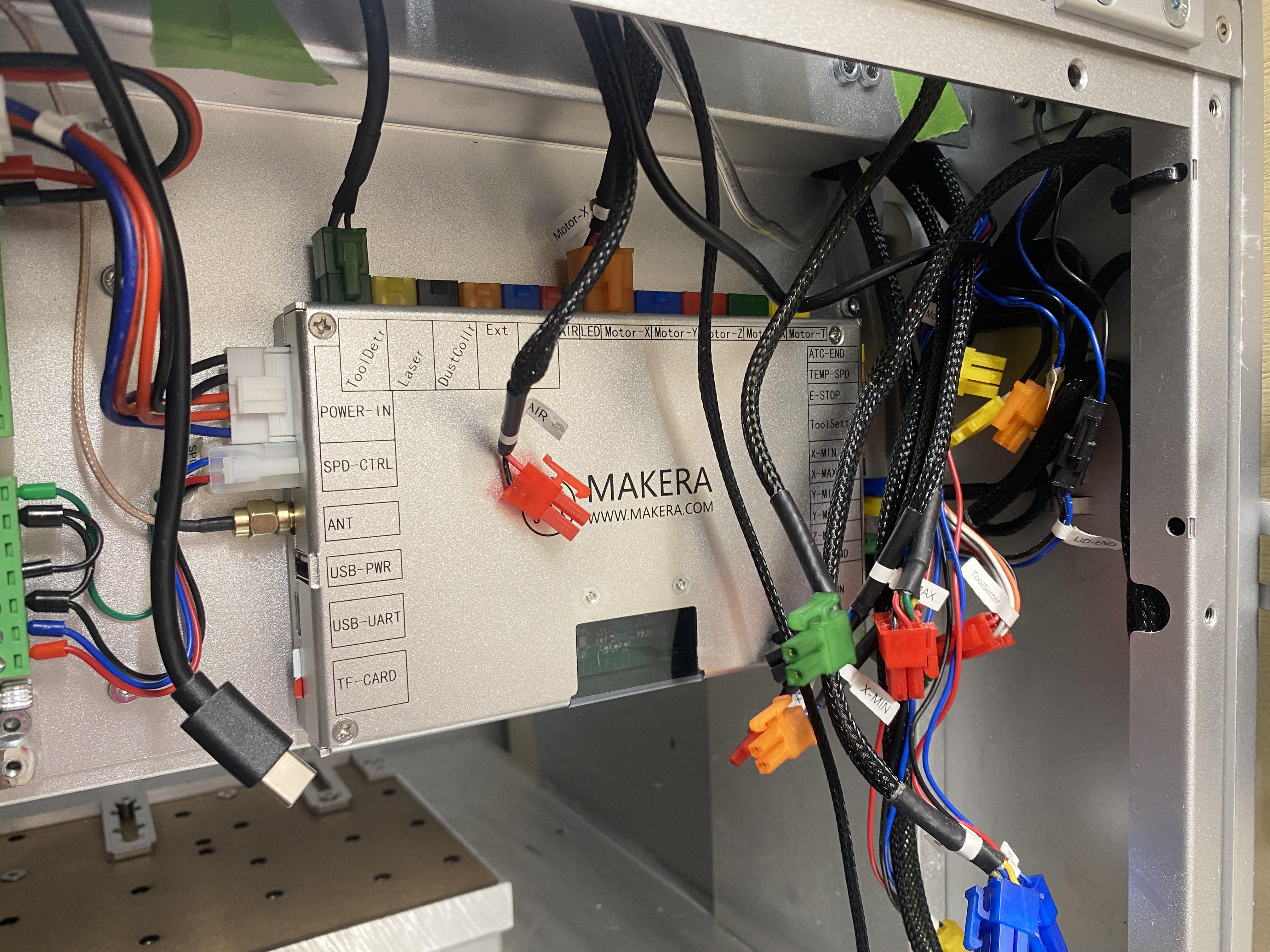
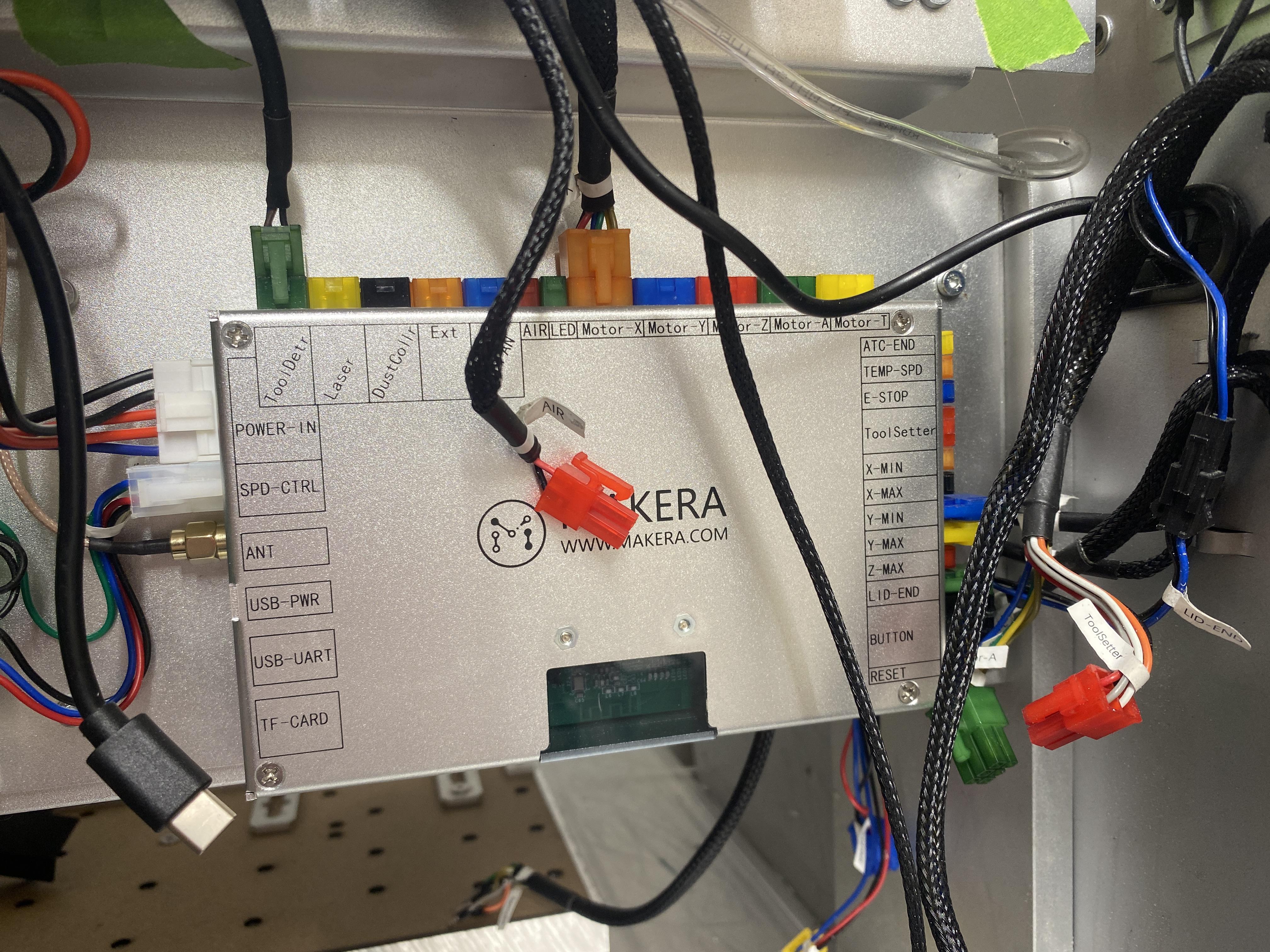
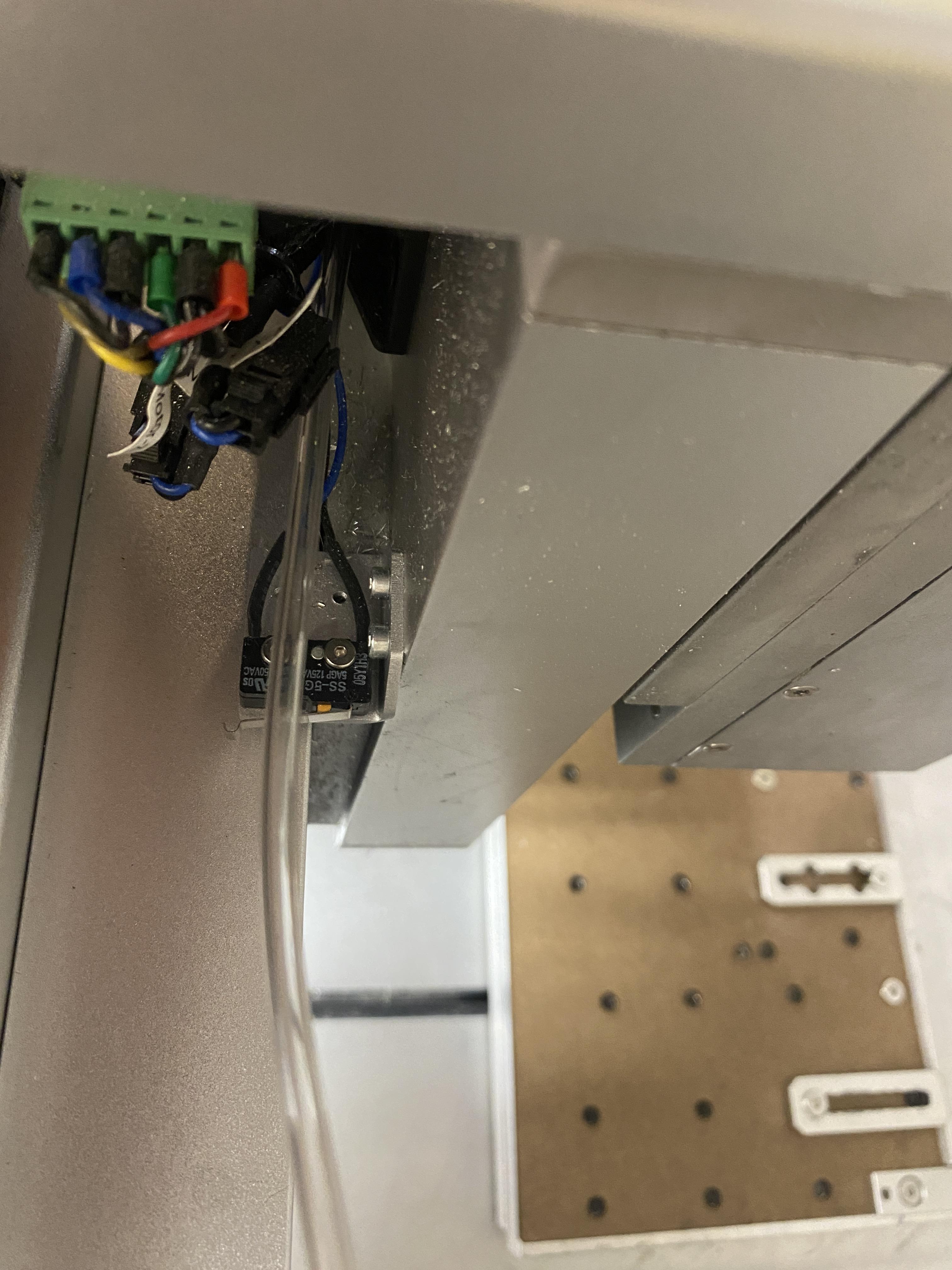
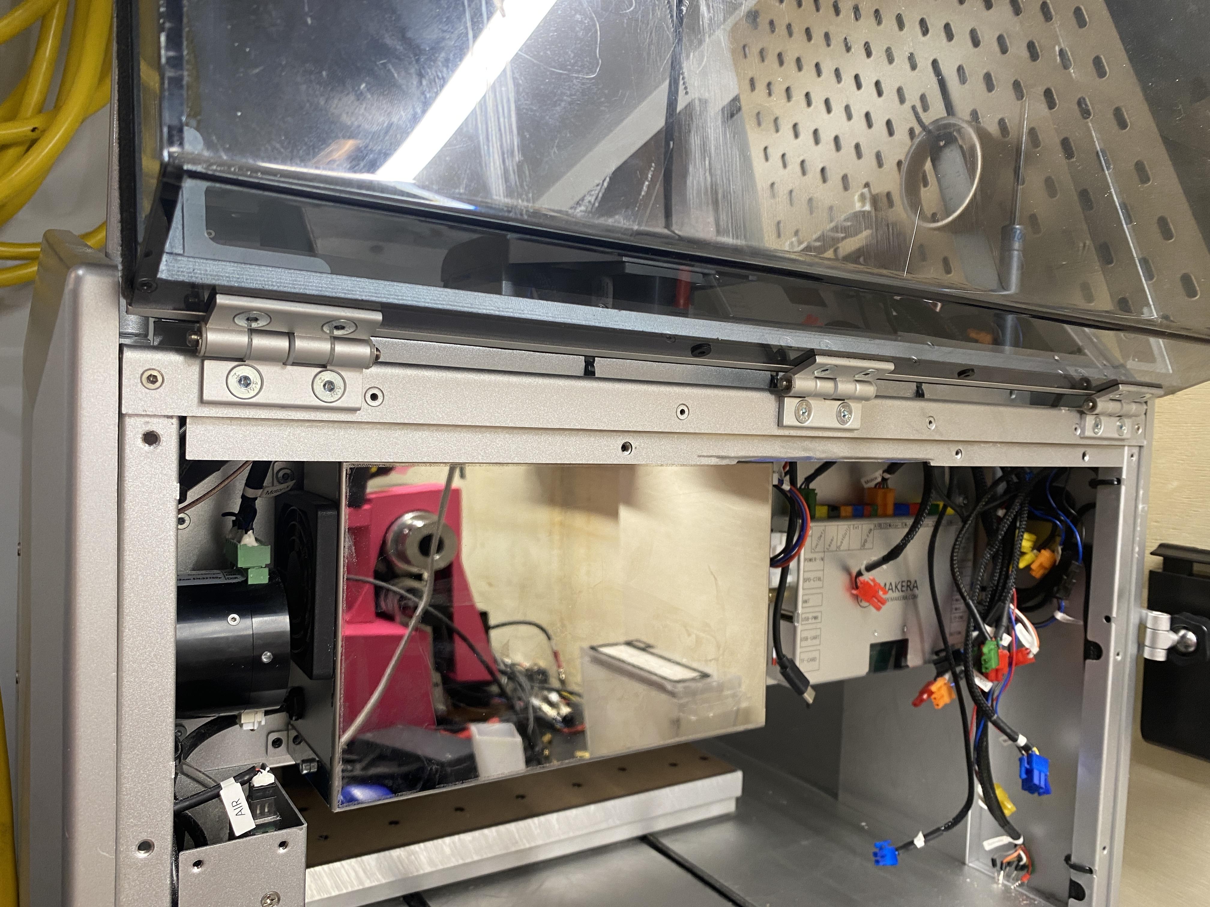
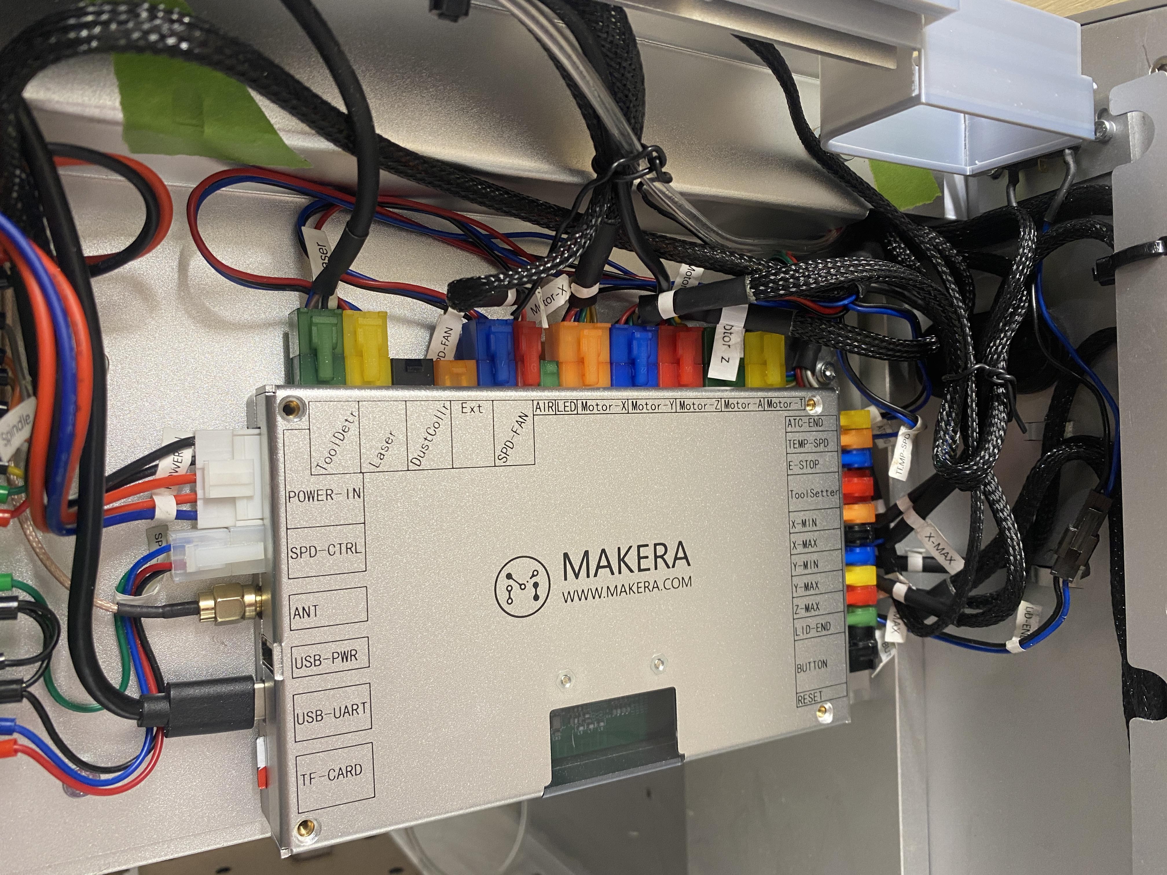
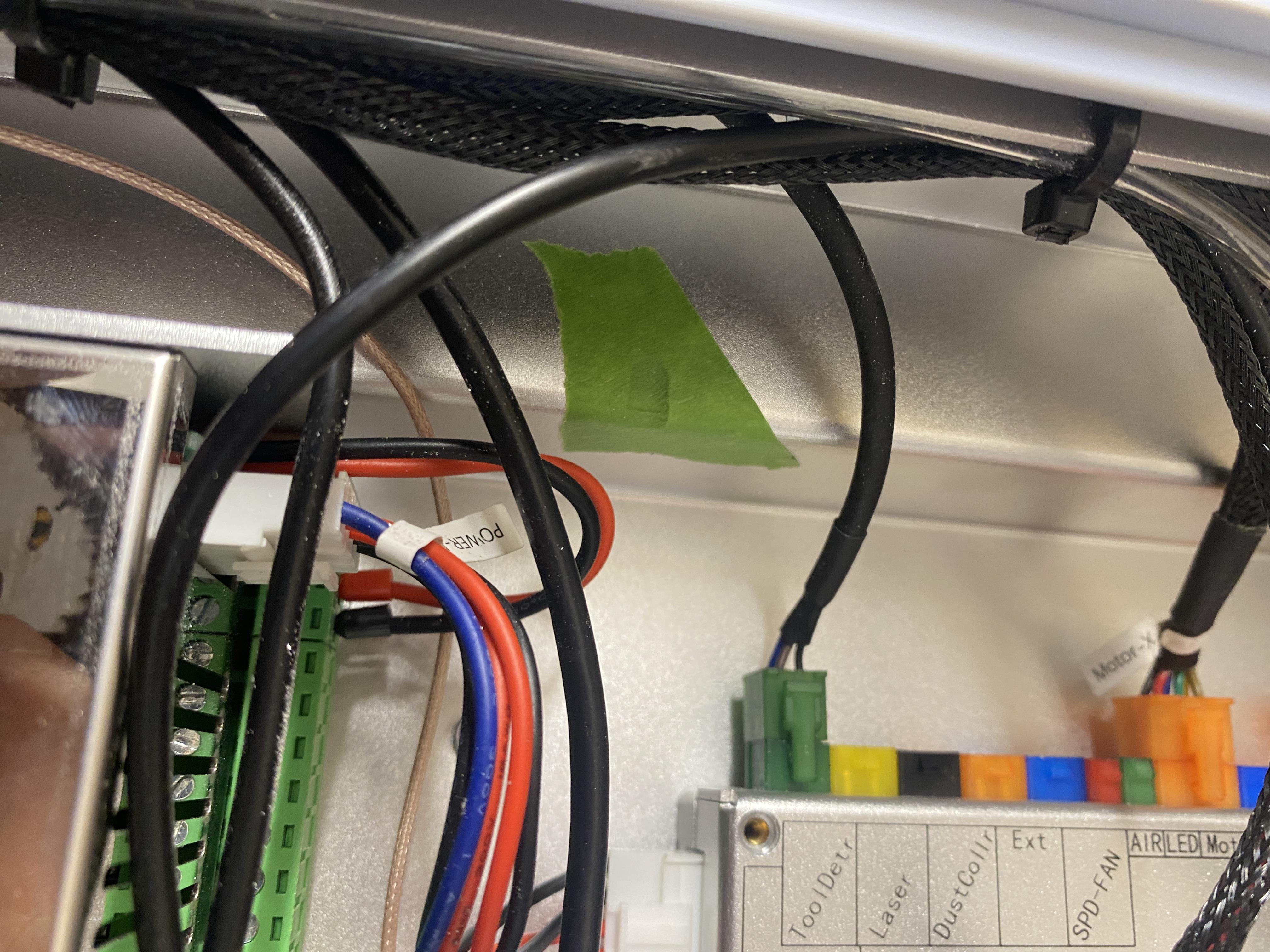
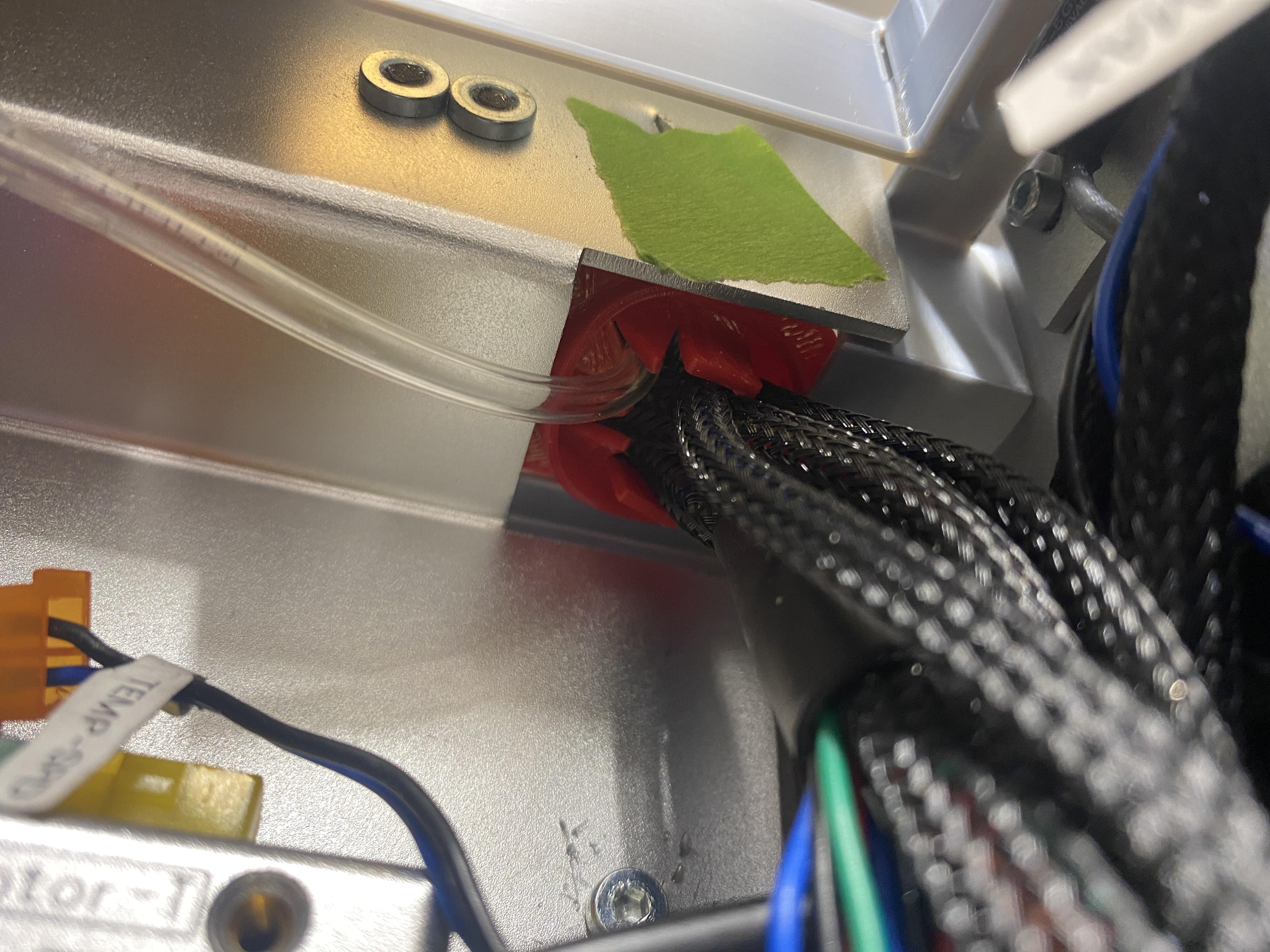
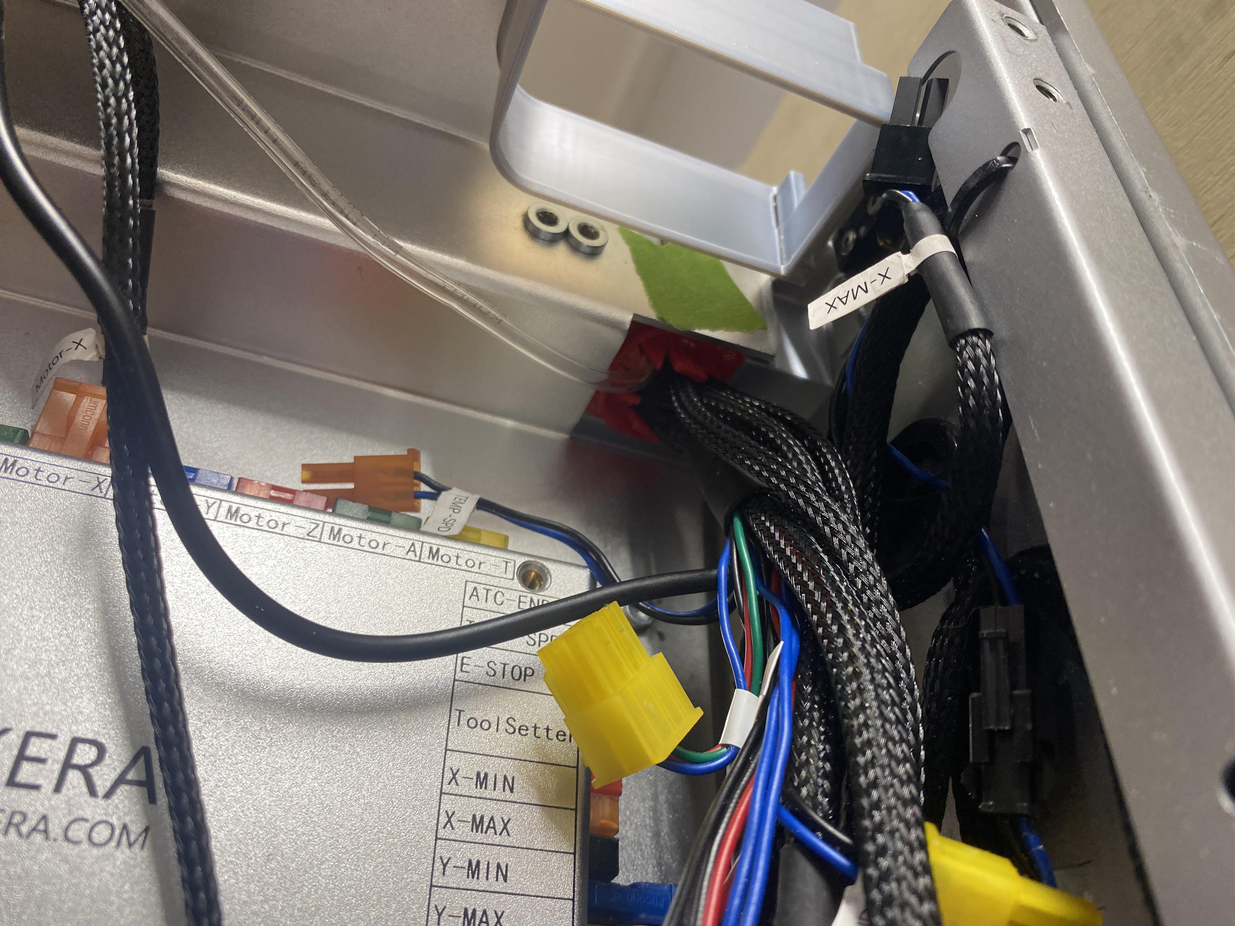
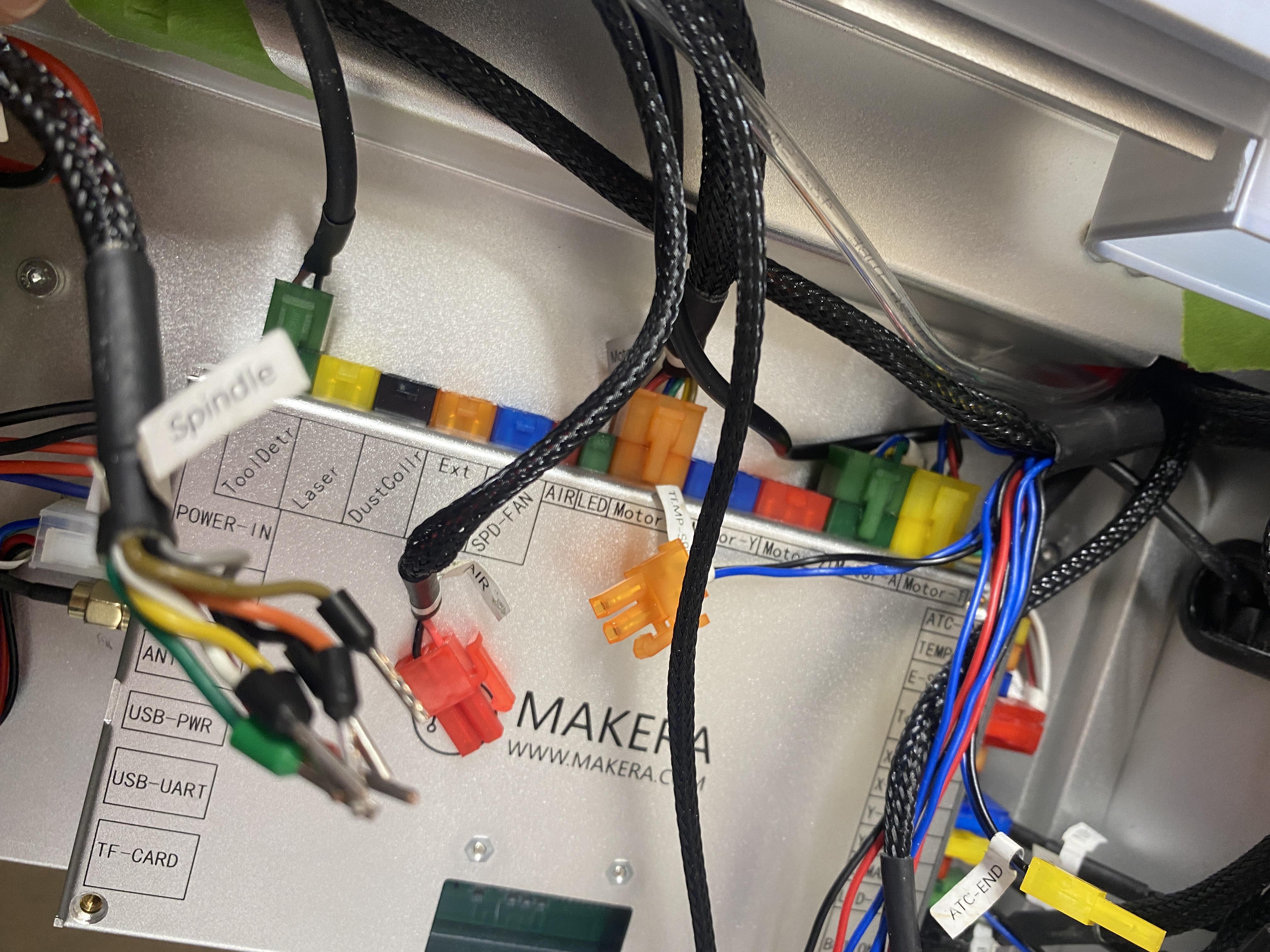
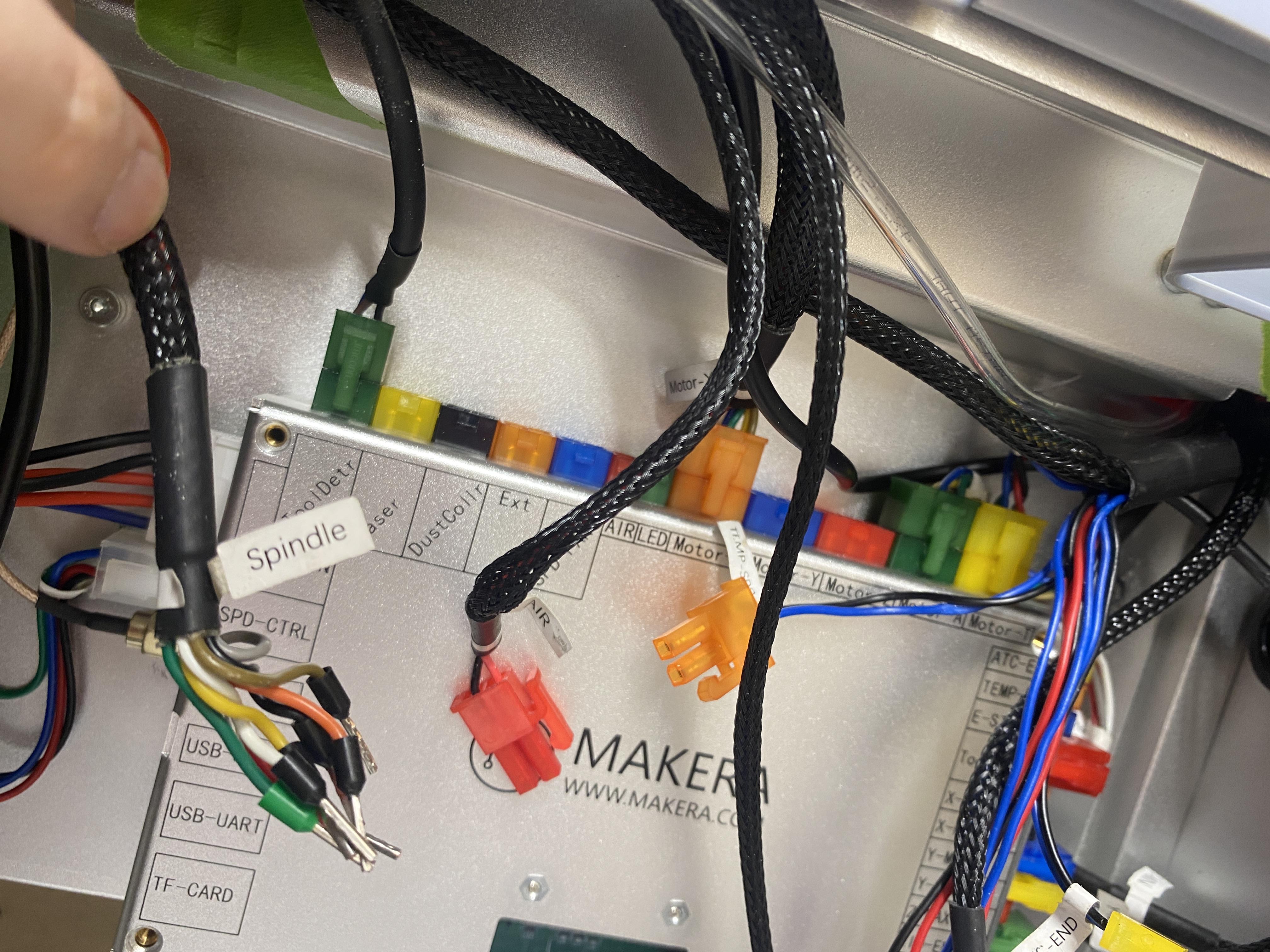
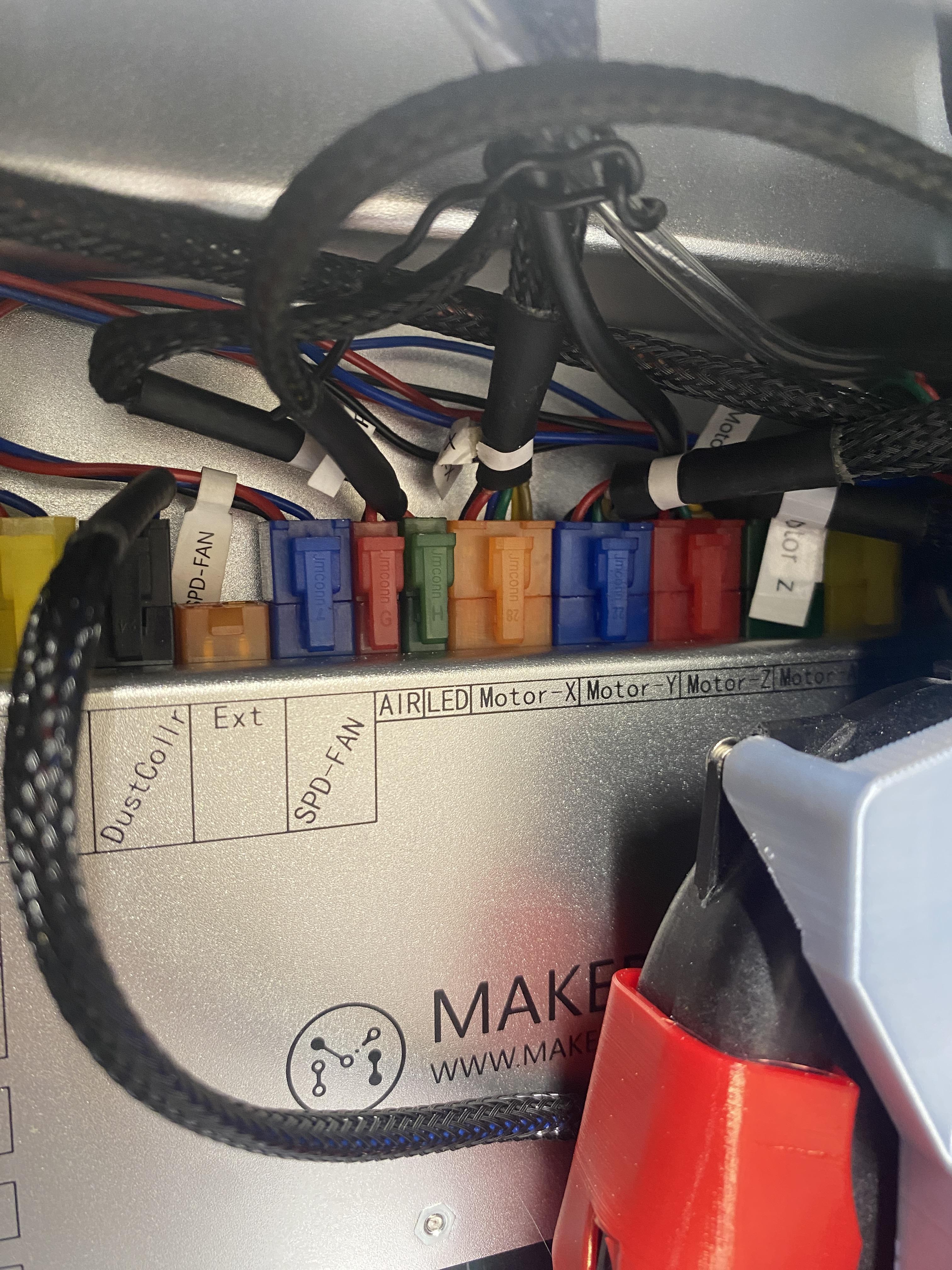
Find all wires going through the hole above the circuit board and disconnect them. Then press them through the hole in the top of the machine. Make sure to take plenty of pictures of the wiring in your machine to make sure it all goes back to the original setup.
Remove Door
Unplug and release the lights cable from the main board. Make sure it is free to move and cut any zip ties holding it down.
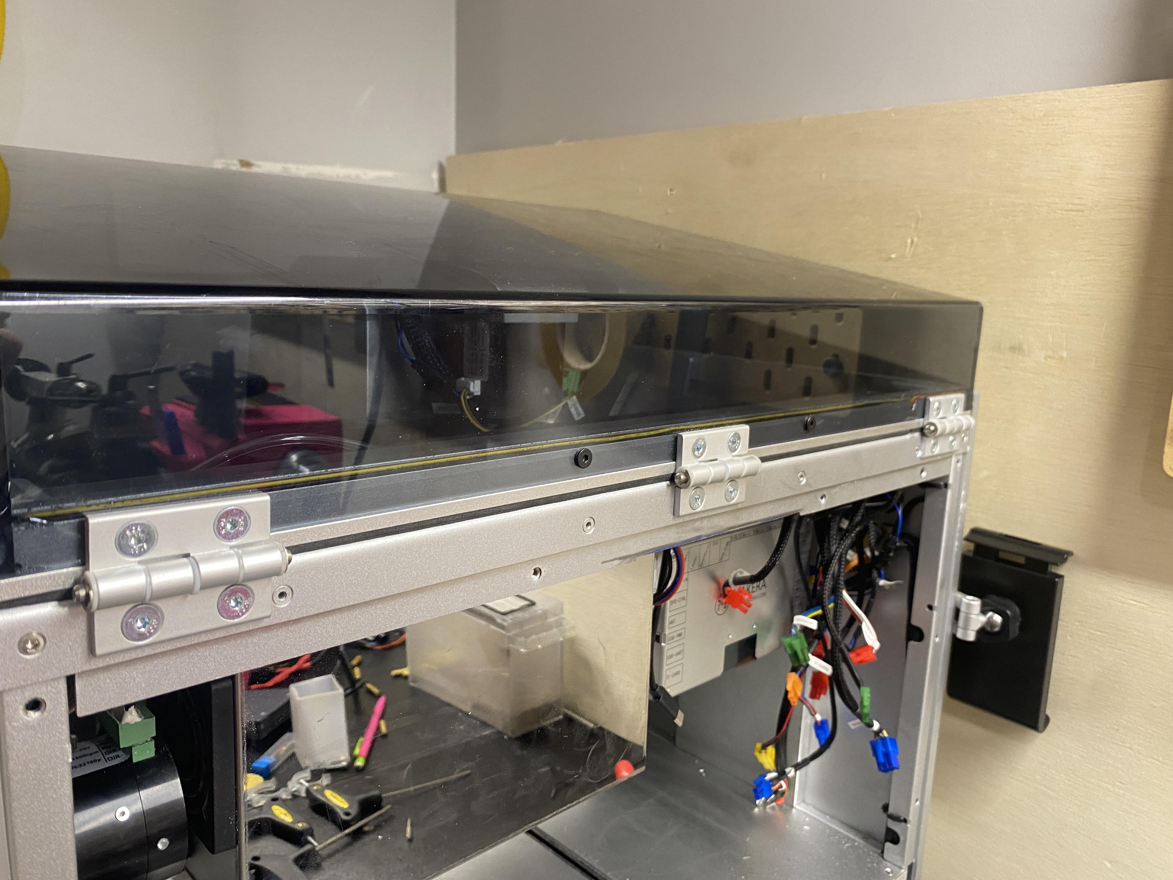
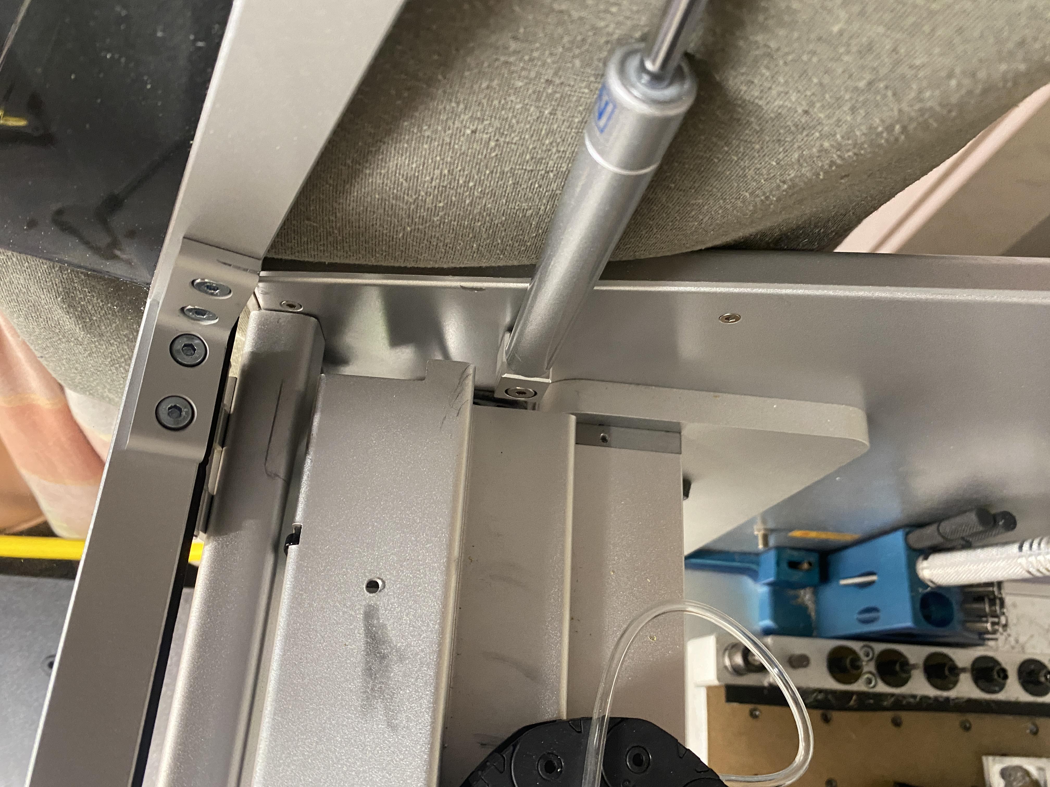
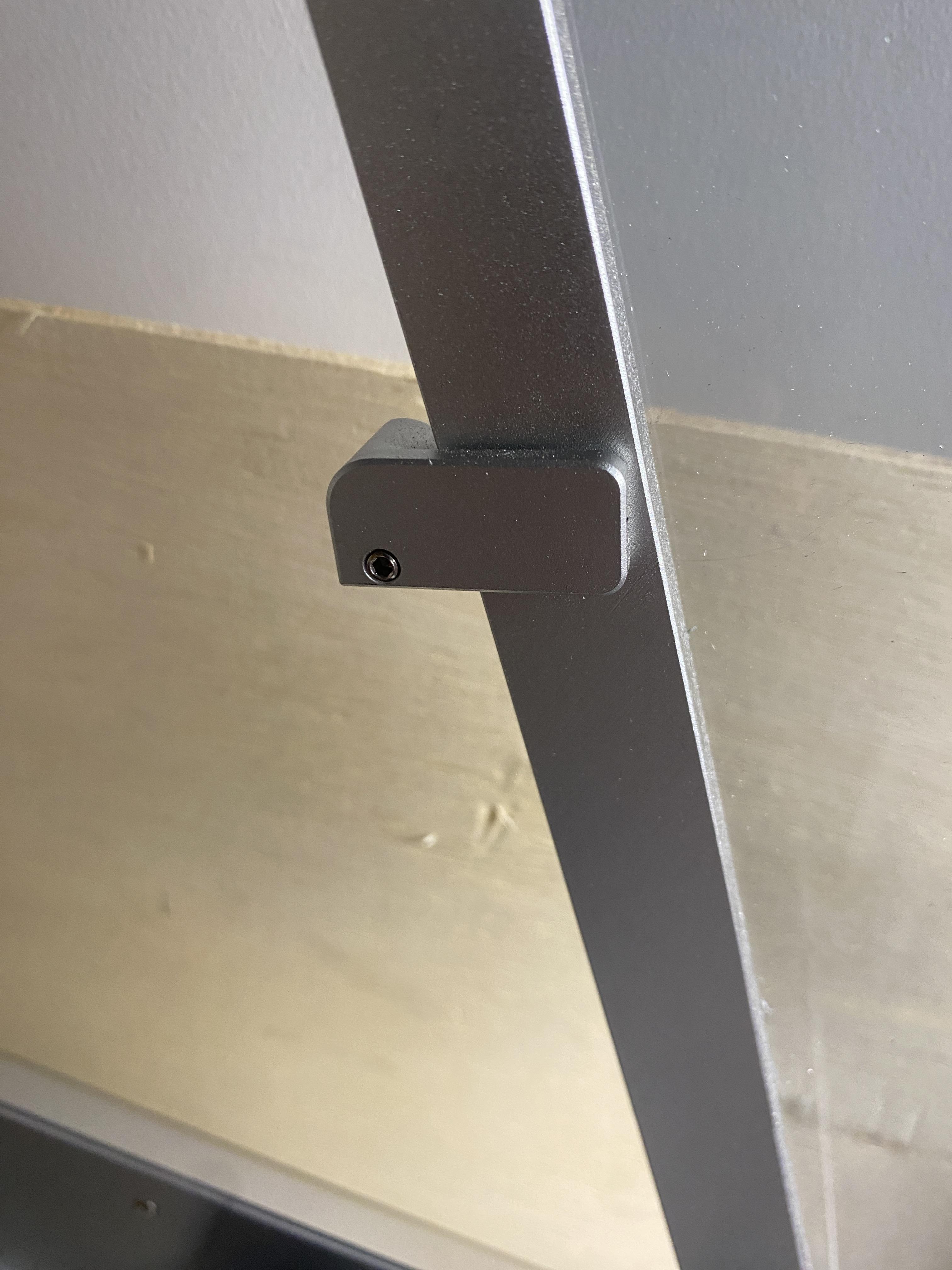
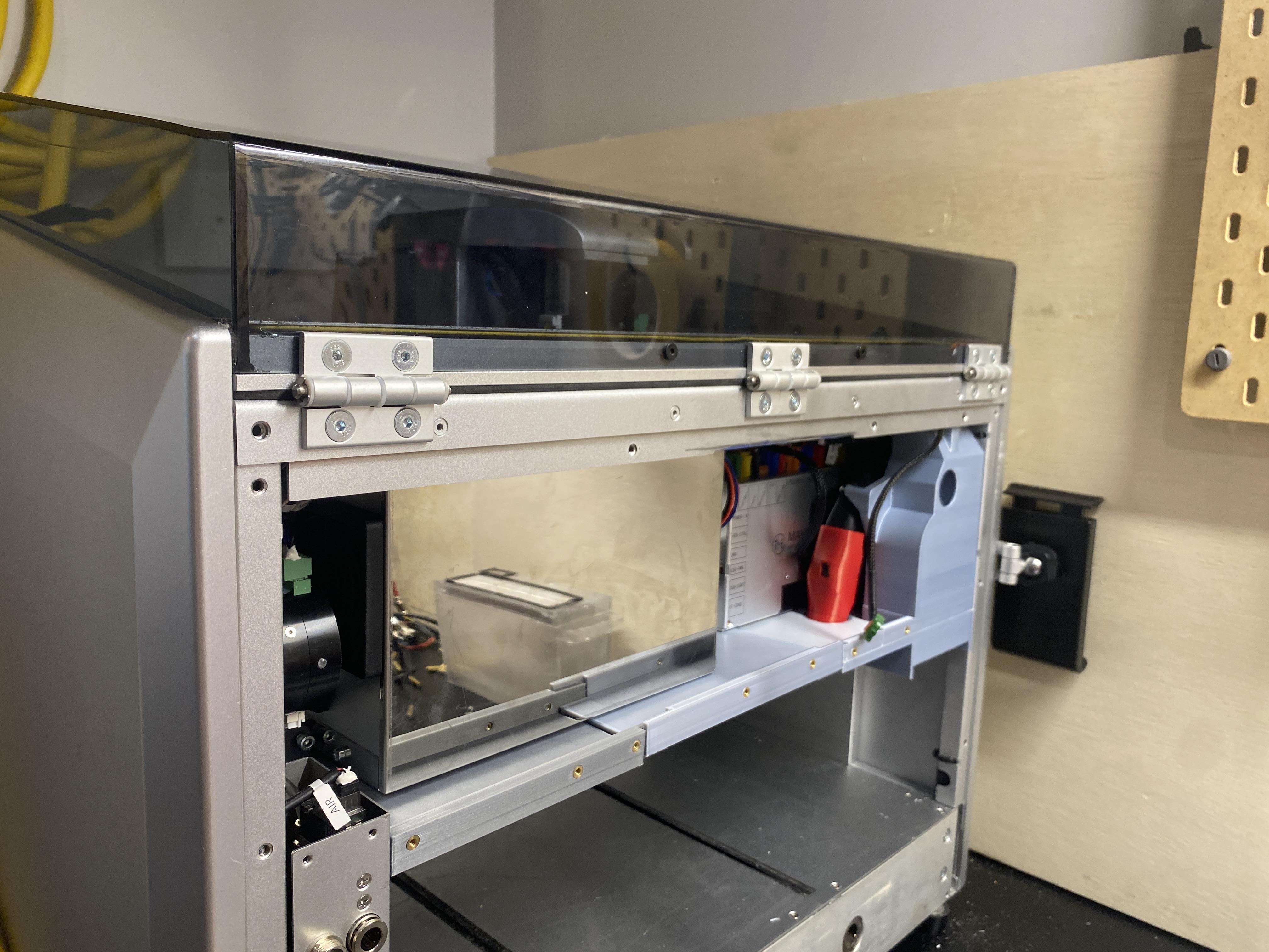
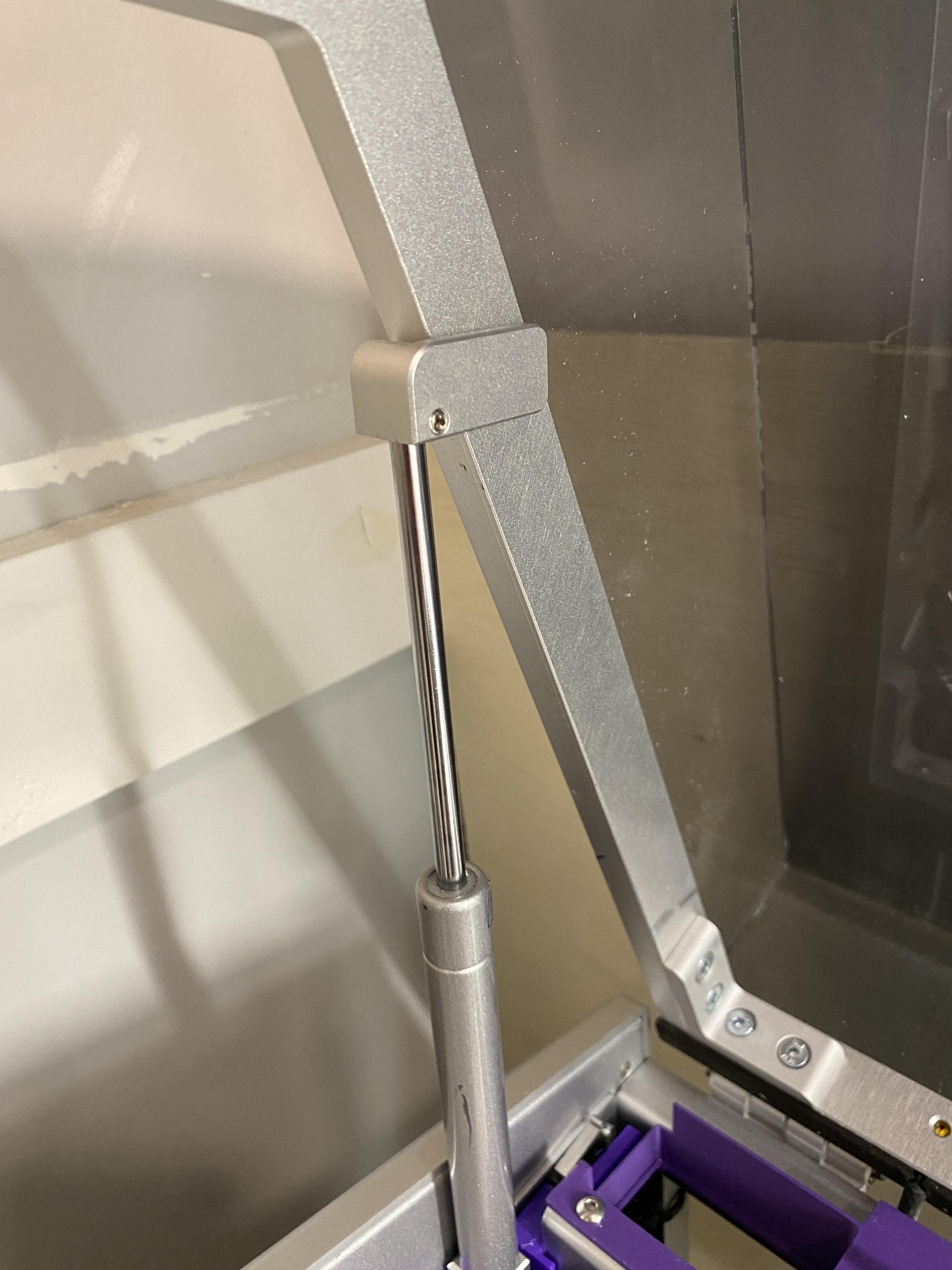
Remove the gas struts holding up the lid on both sides by removing the bolt at the bottom and loosening the set screw at the top.
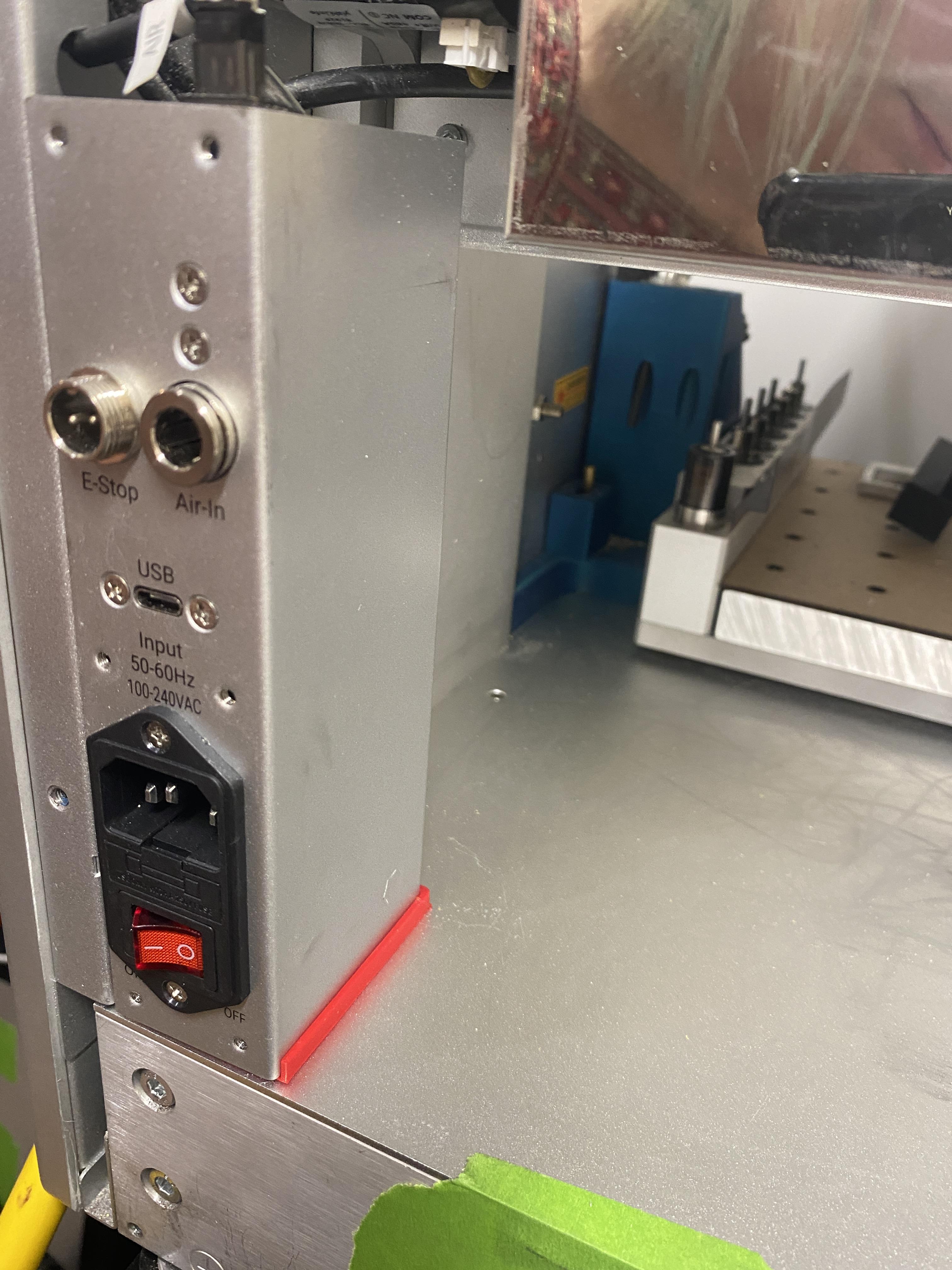
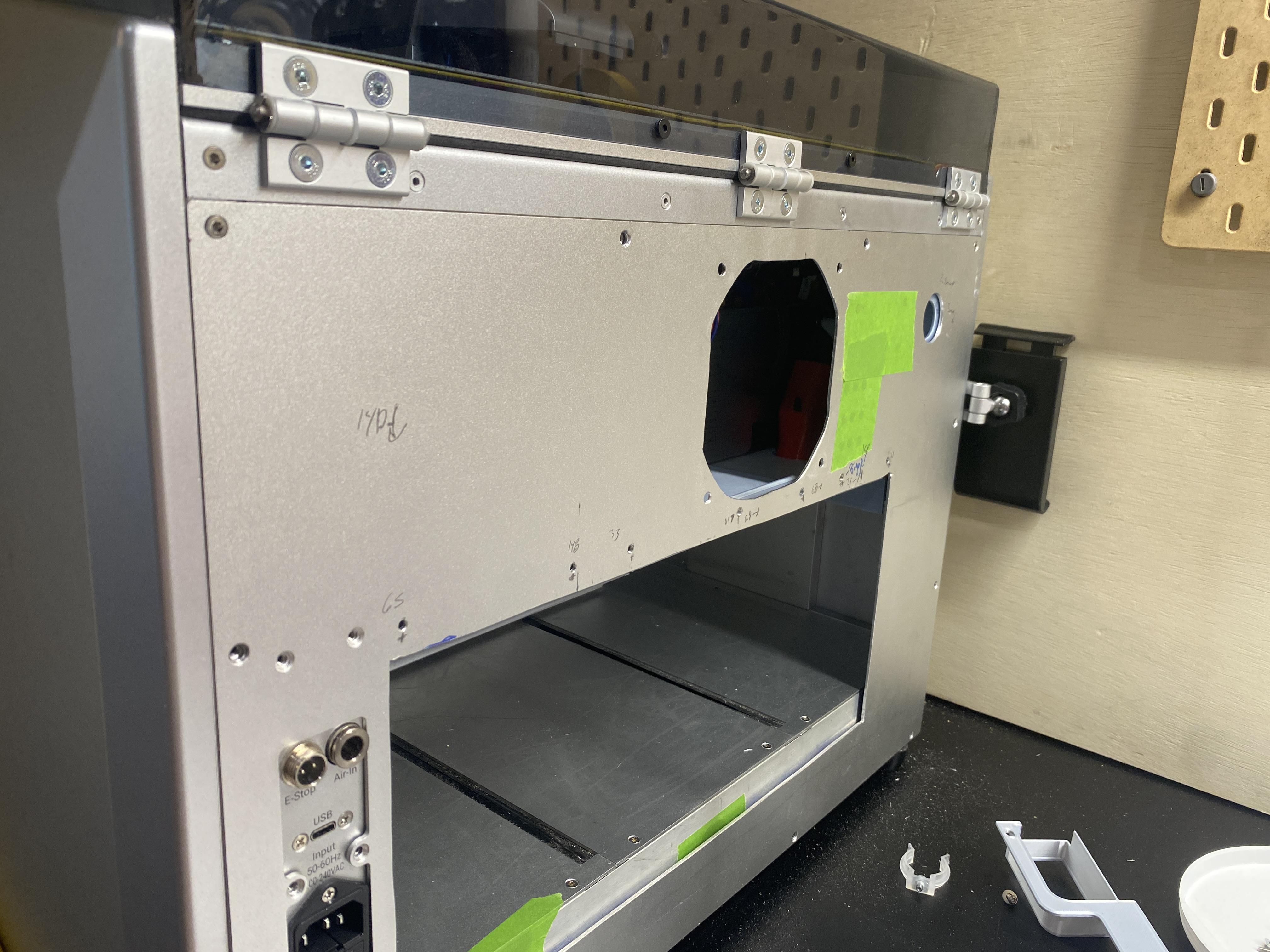
Unscrew the two bolts holding the lid onto the back of the machine. The bolts are marked in red in the image
Lift the lid straight up off the machine.
Install Wire Grommet
.JPG)
.JPG)
.JPG)
.JPG)
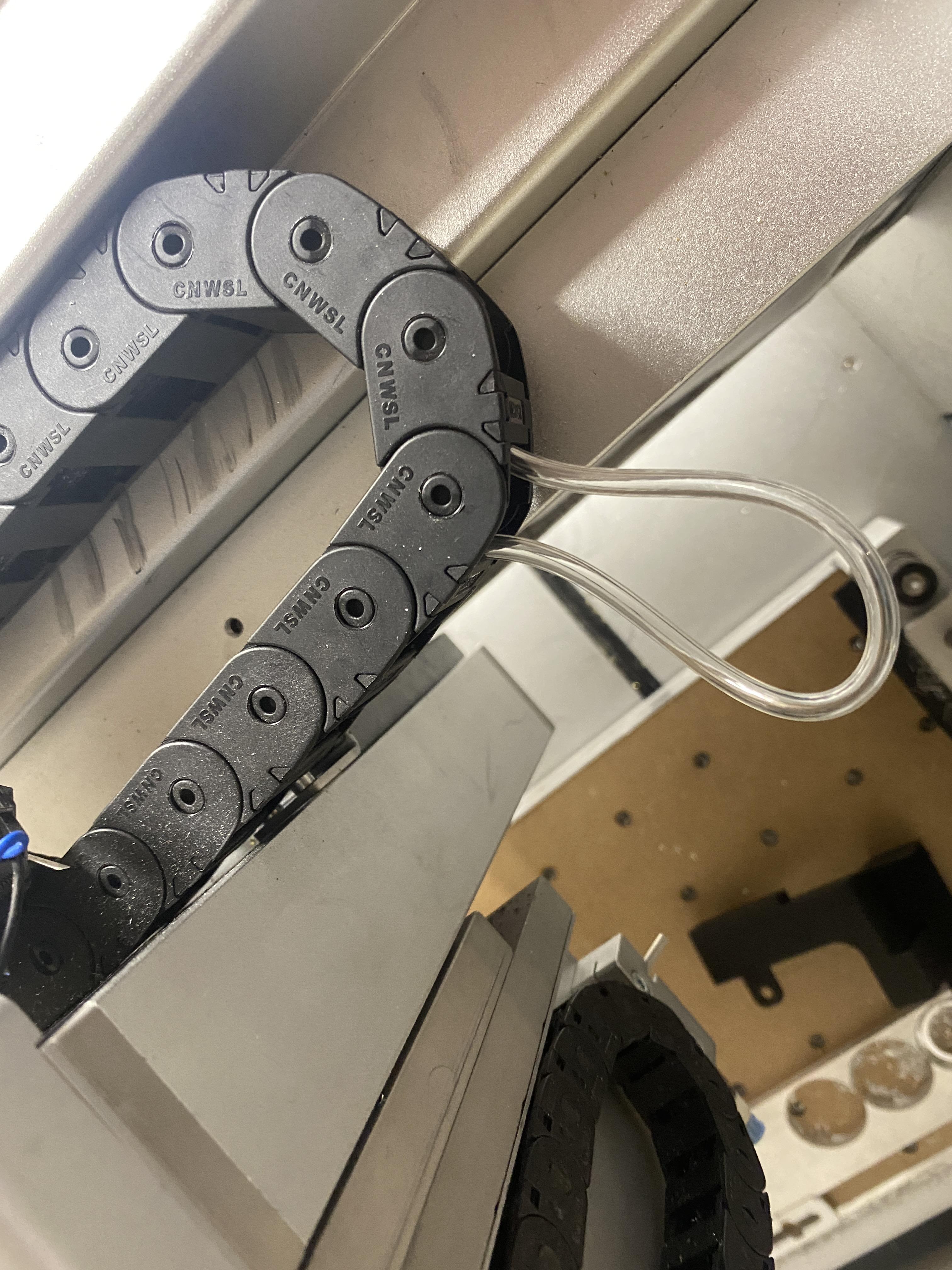
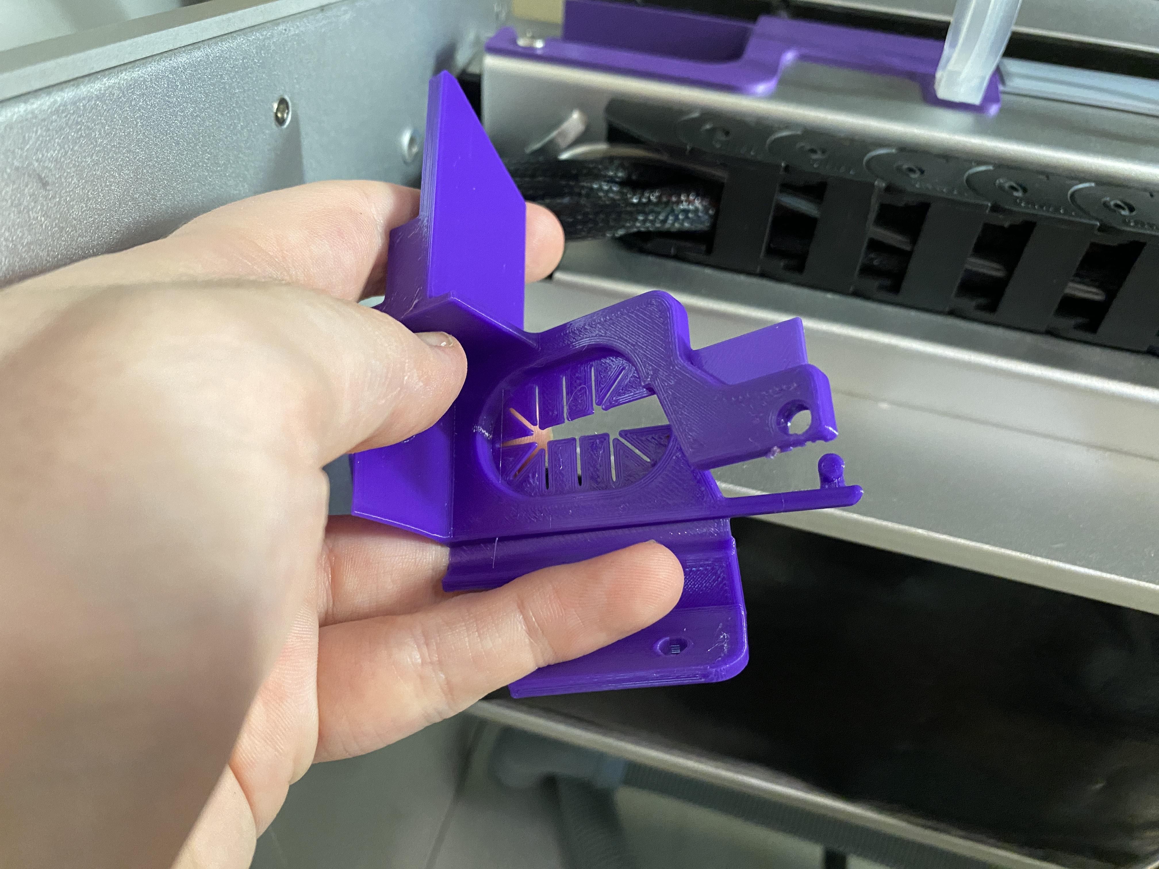
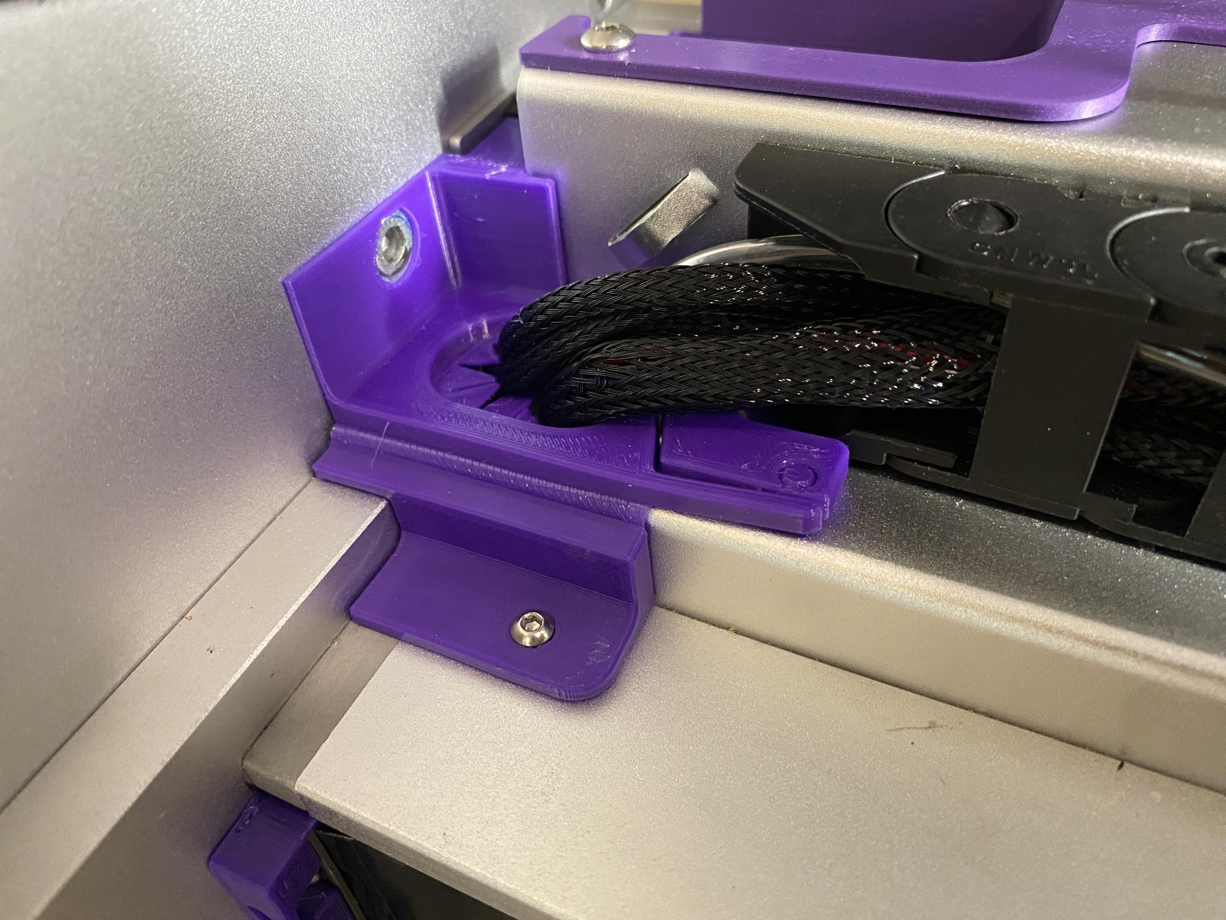
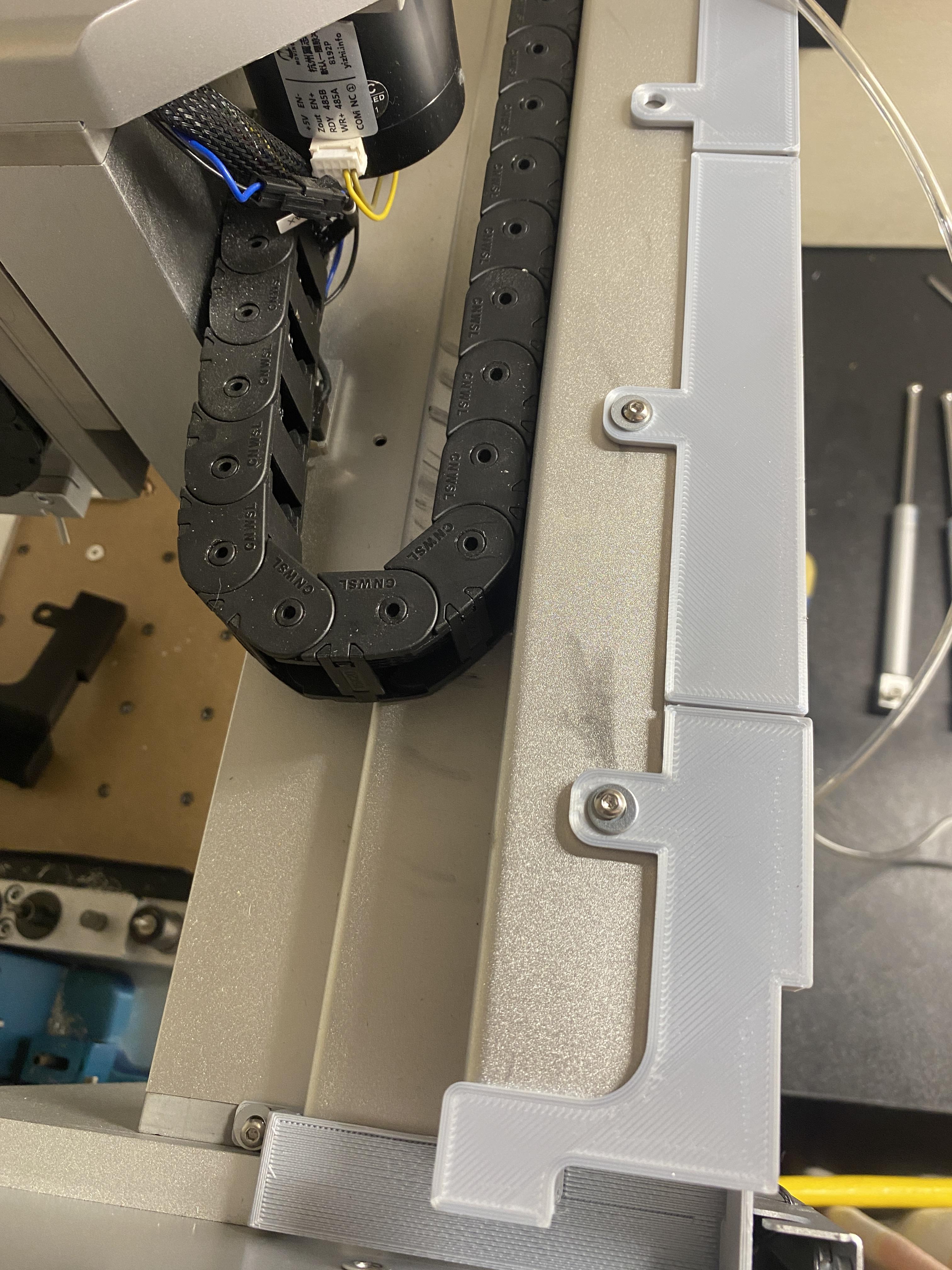
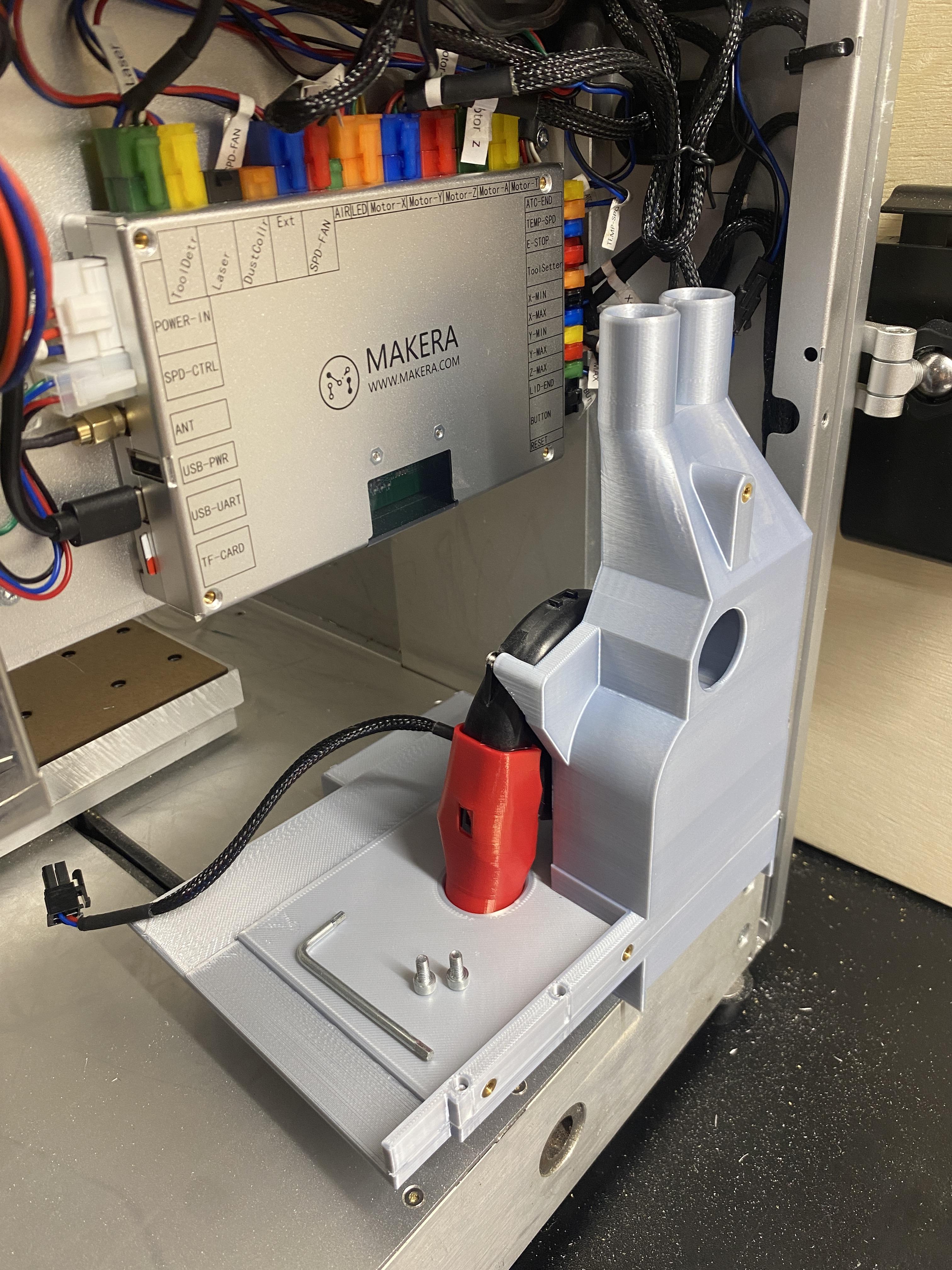
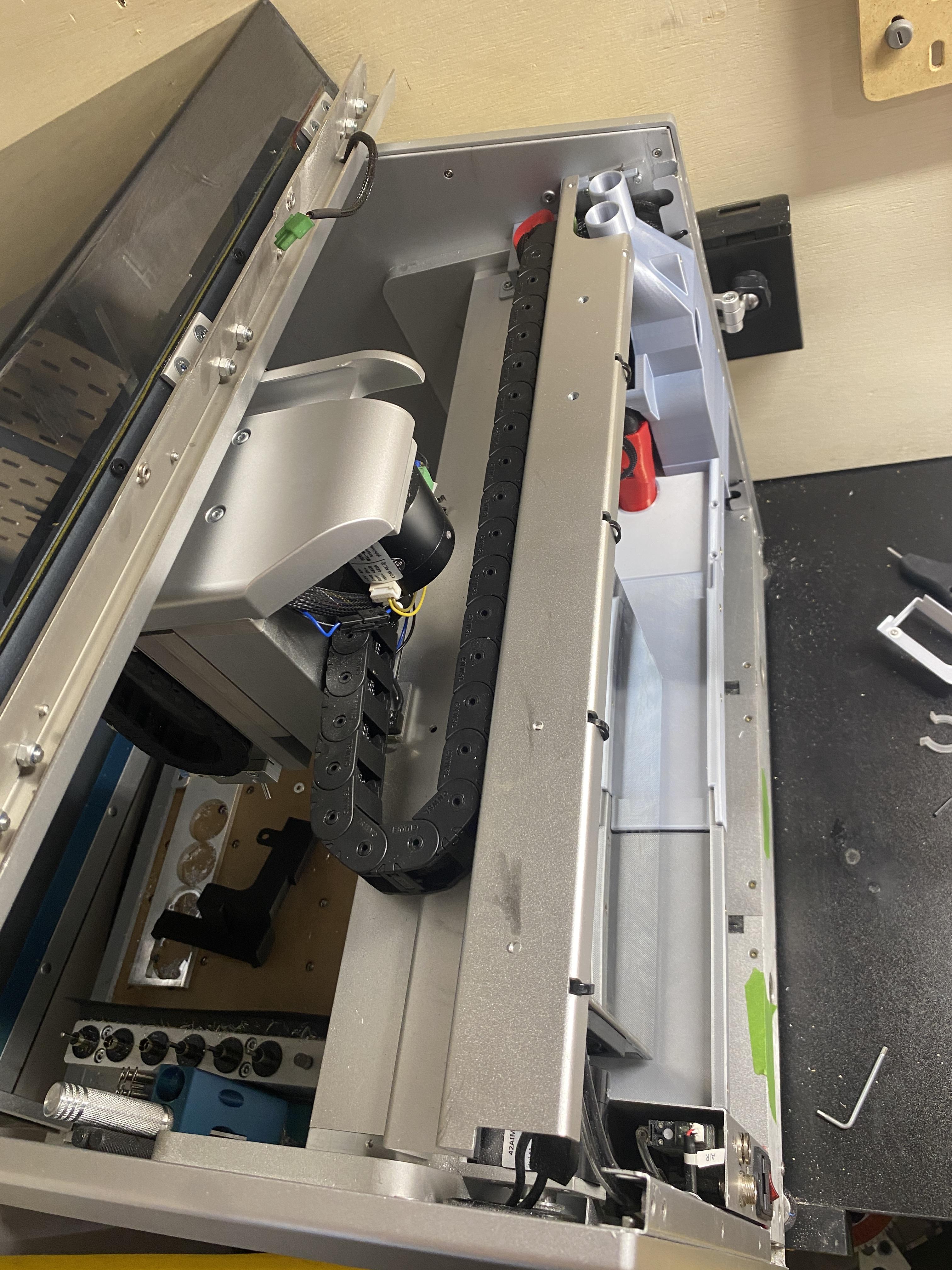
Open the cable grommet as shown in the first image
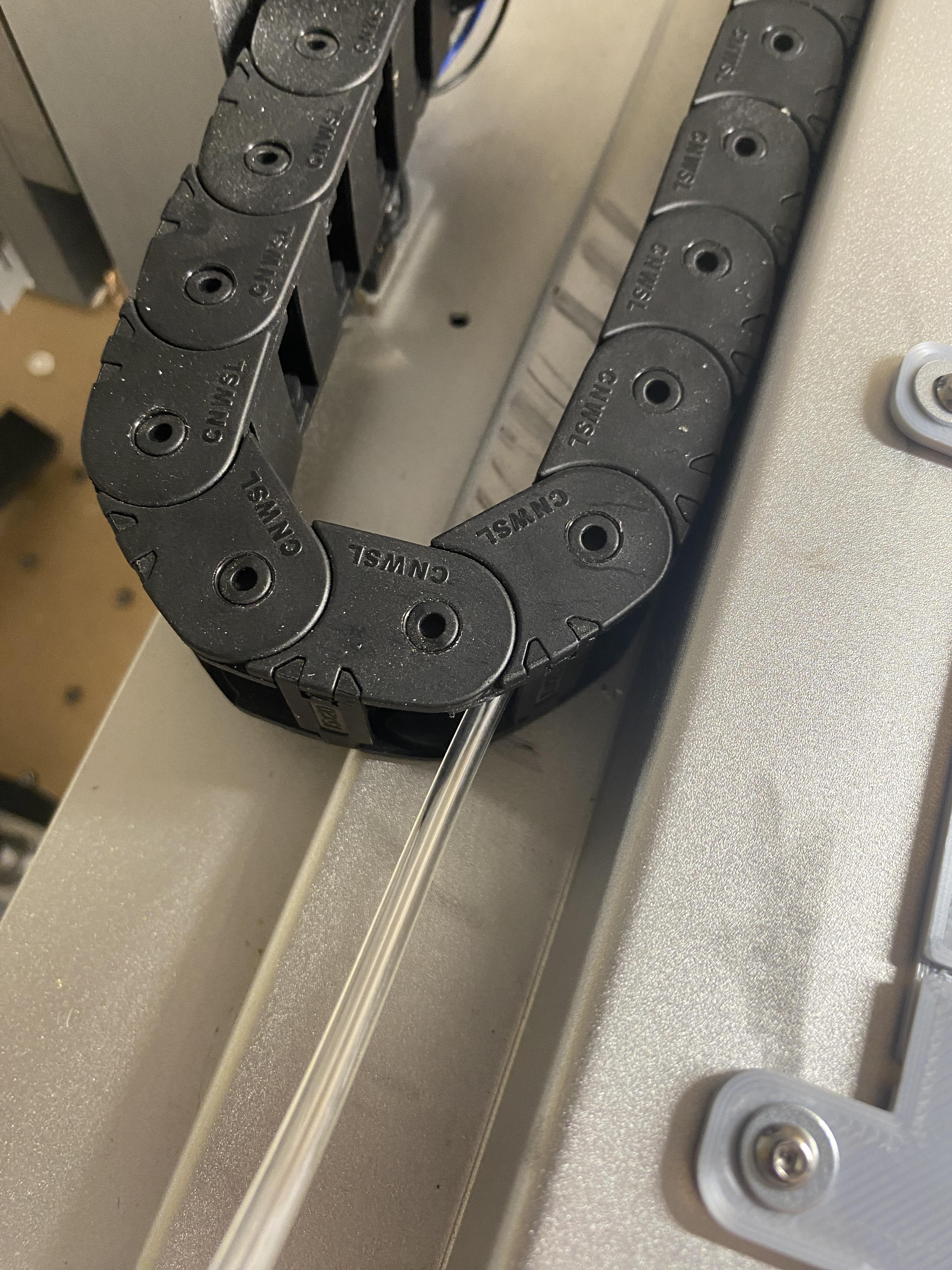
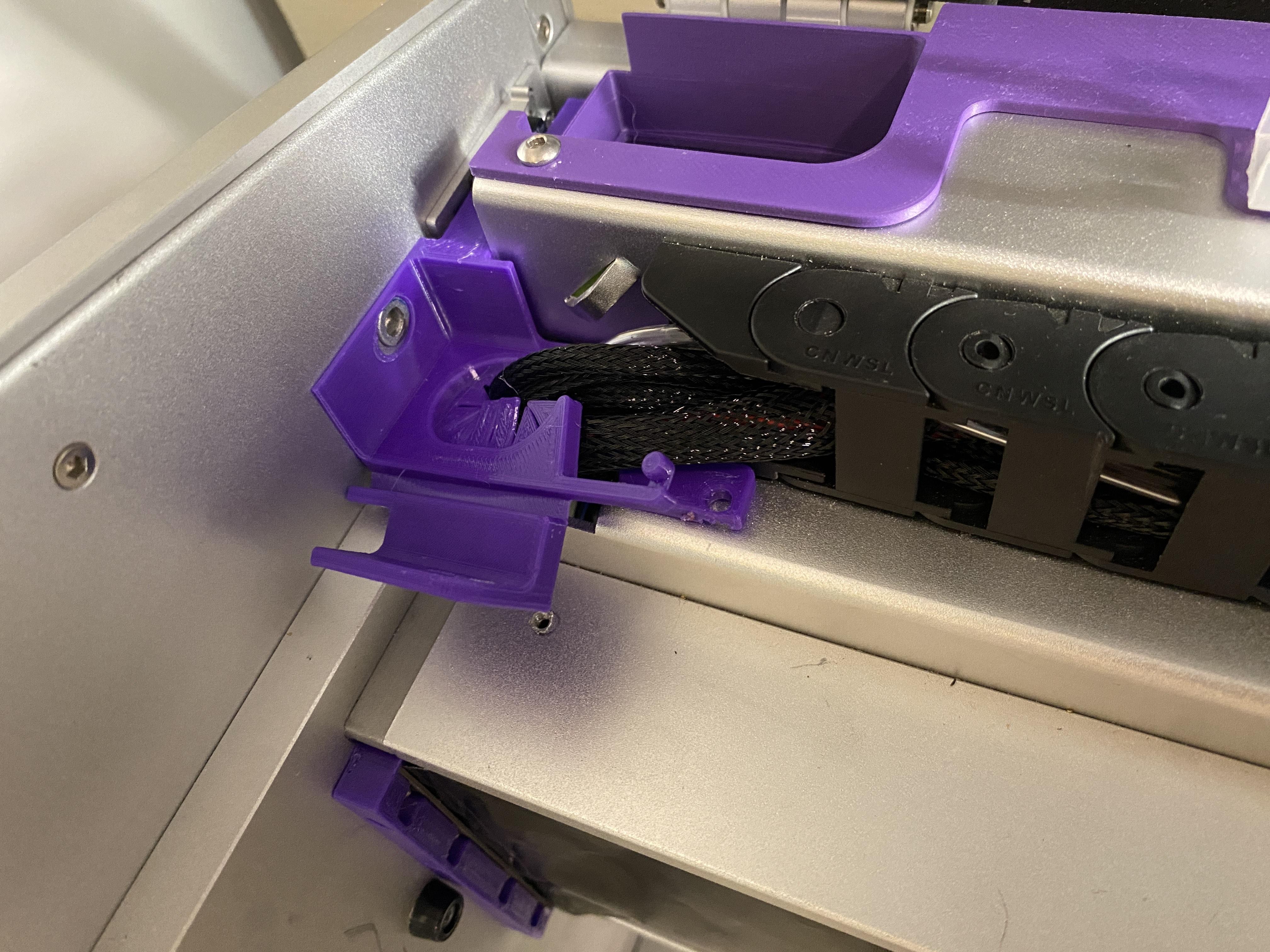
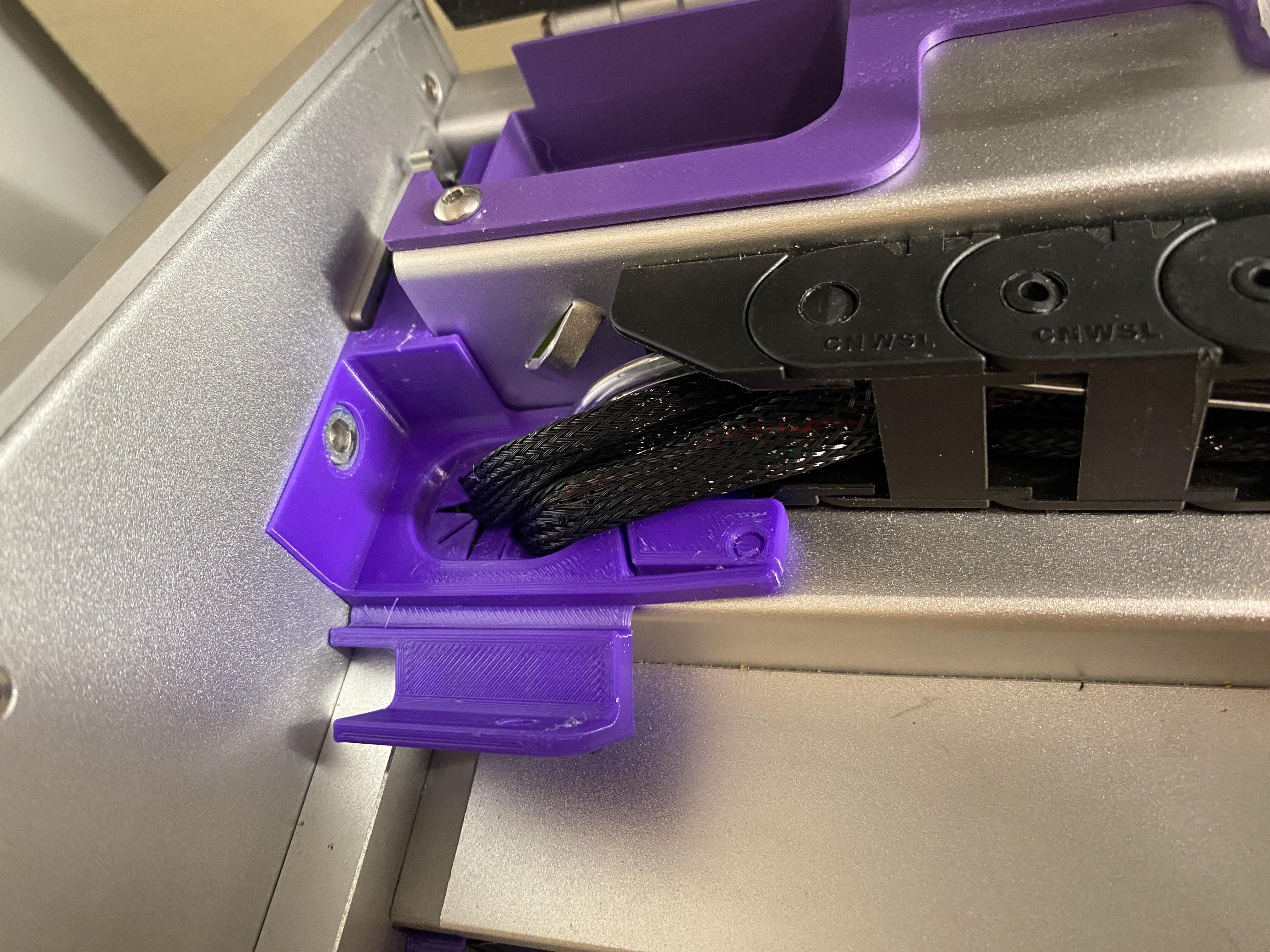
Slip the grommet behind the cable wrap. You will have to press down the fingers around the cable to make sure it lies flat and there is a small piece that goes under the cable chain to hold it in place.
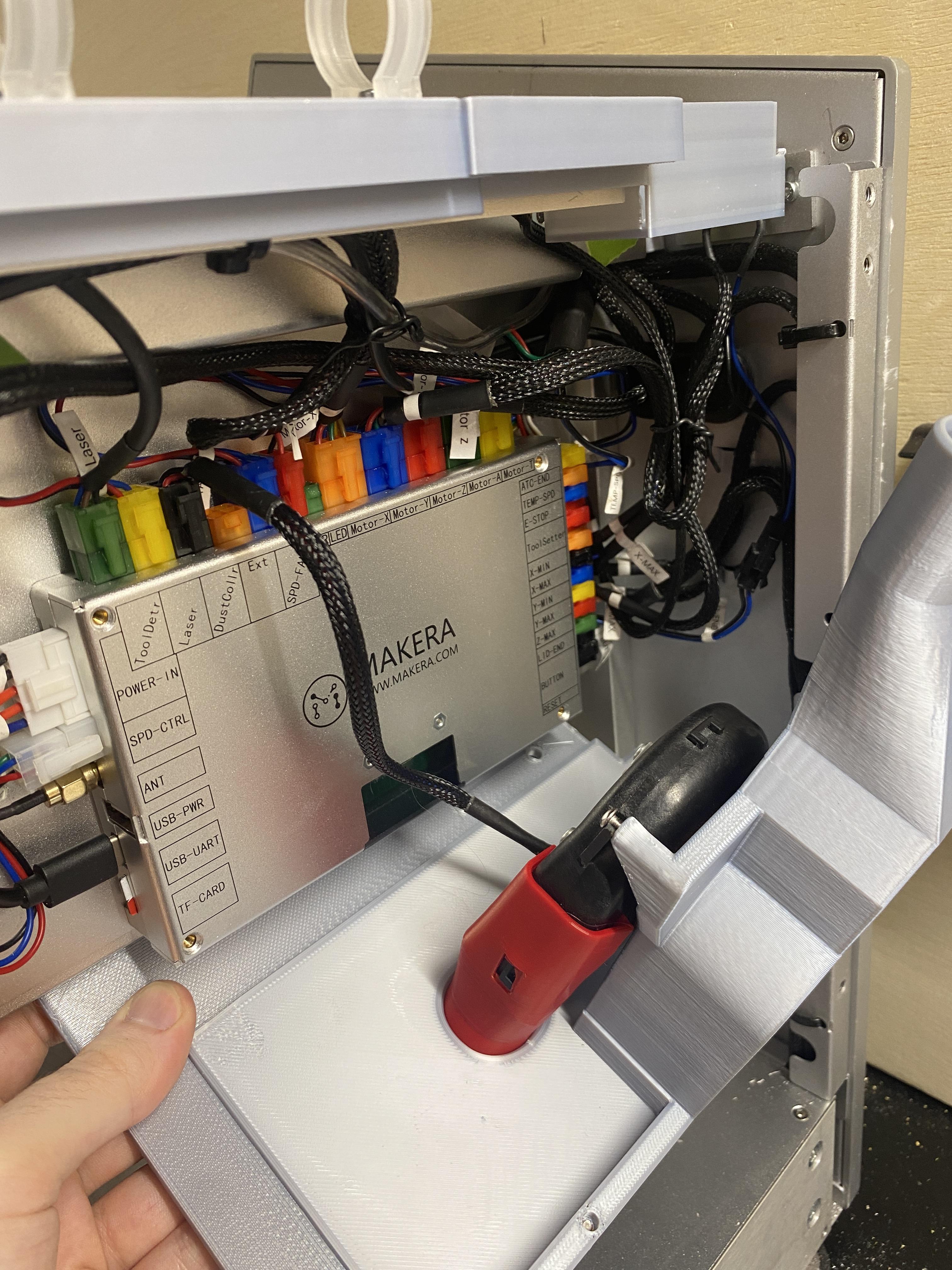
Connect the two sides of the cable grommet as shown and make sure the whole piece is laying as flat as possible
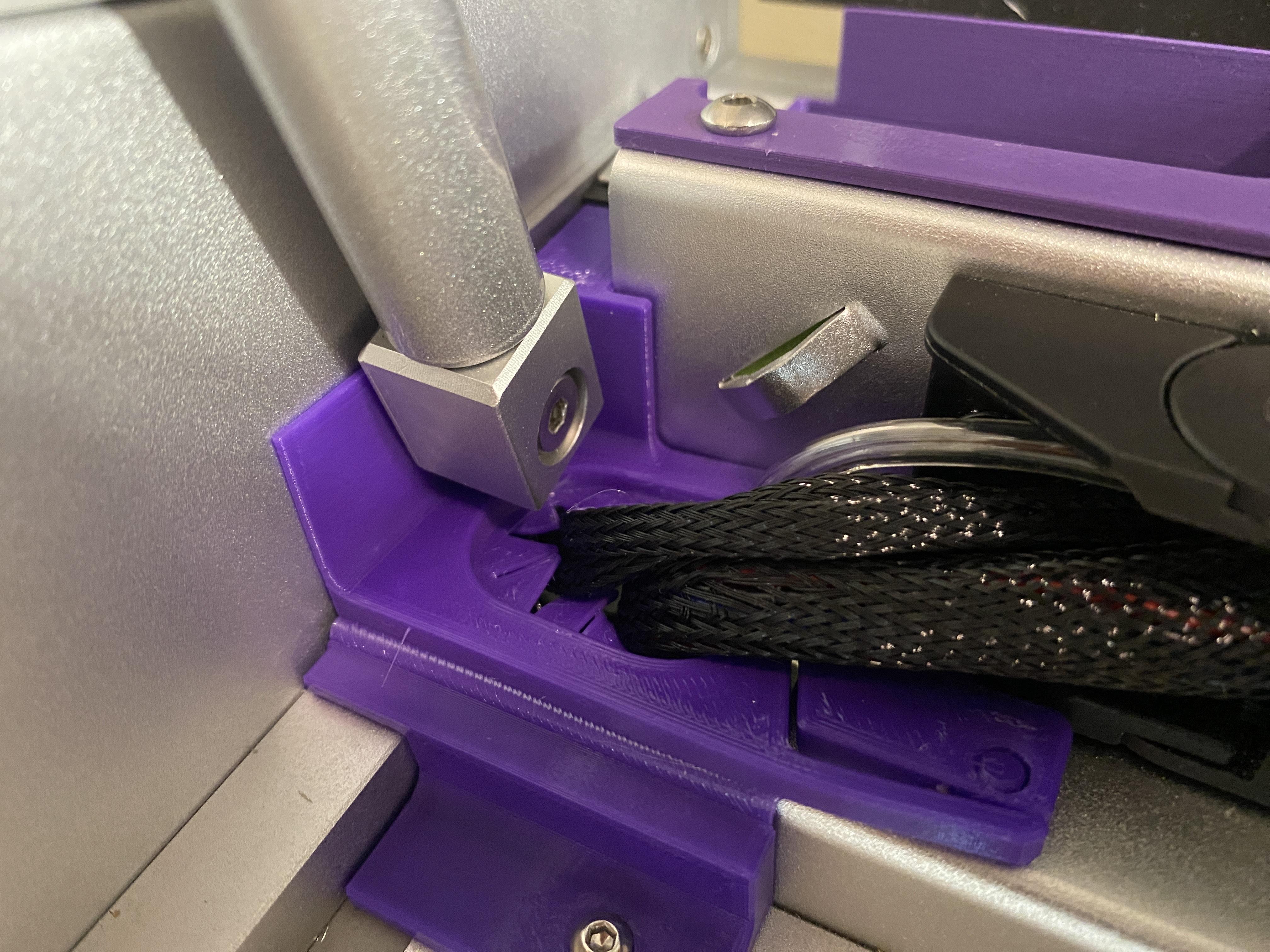
Press the bendable arm down, mark and drill/tap the single screw hole for M3. As you are drilling the hole, check to make sure you wont drill through anything important (removing the x axis cover is helpful in this process)
Make sure the hole is lined up with the gas piston mounting point and reinstall the lower part of the gas piston. We will install the upper section of the gas piston later.
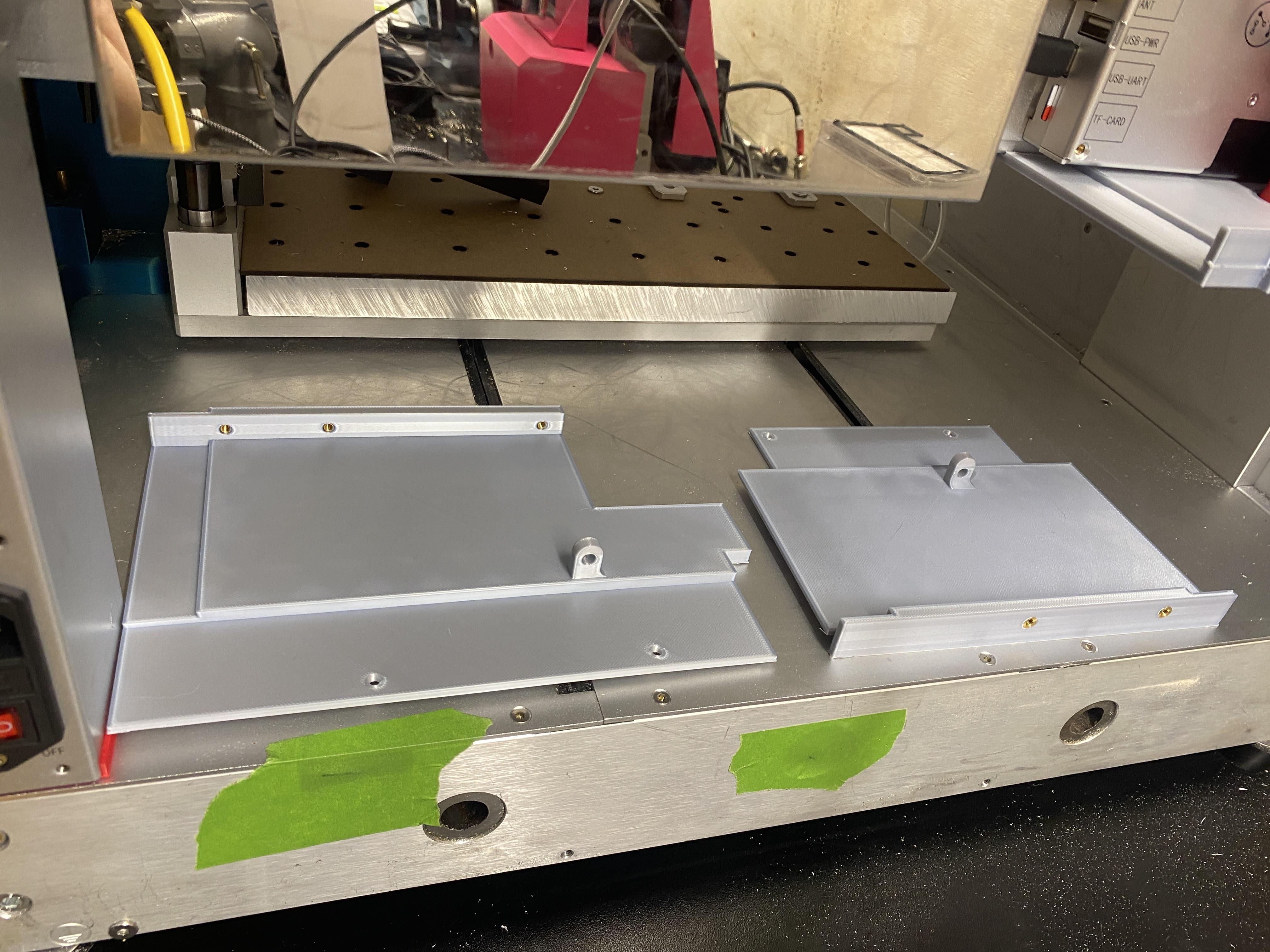
Install Top Cover Pieces
.JPG)
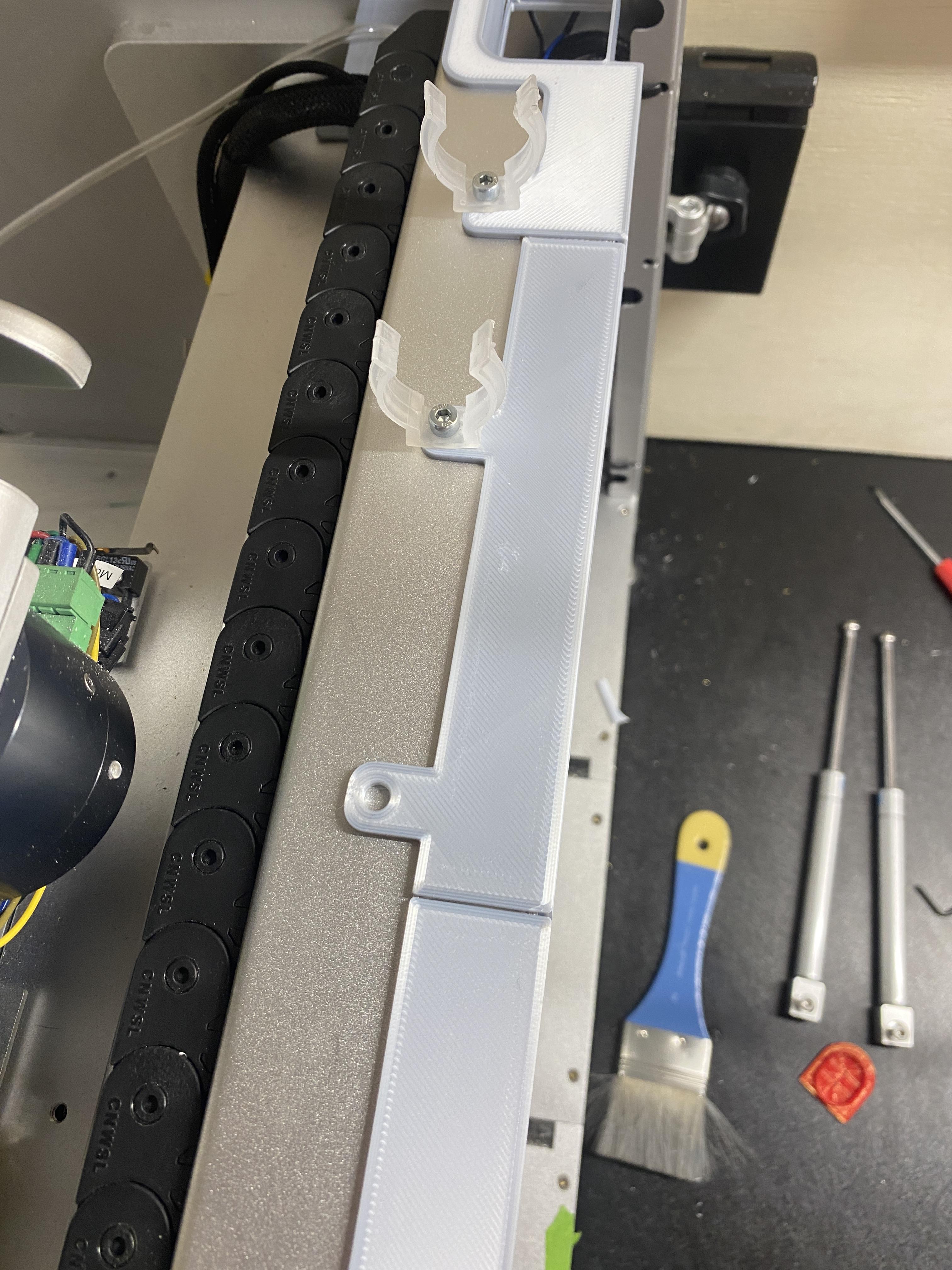
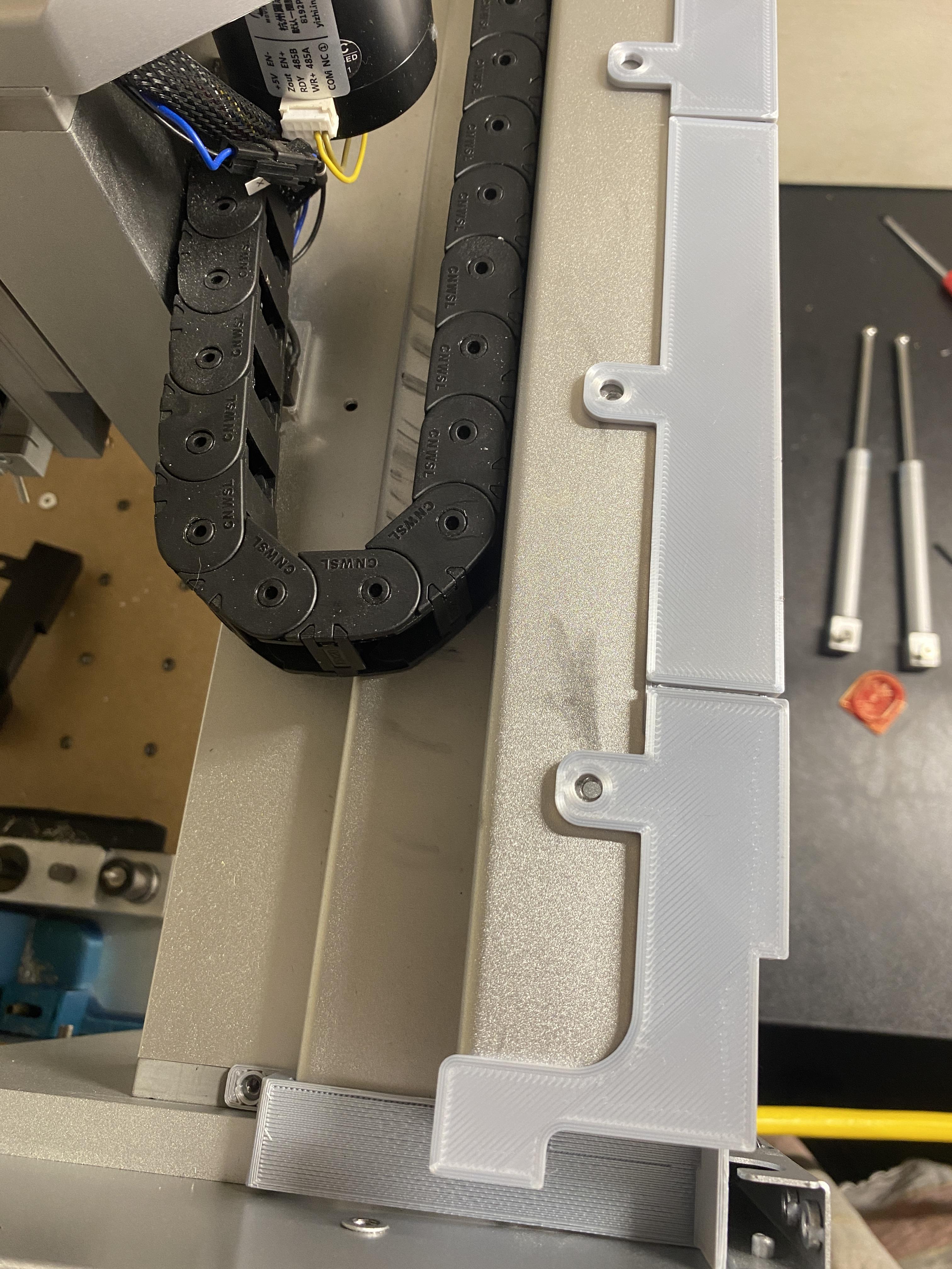
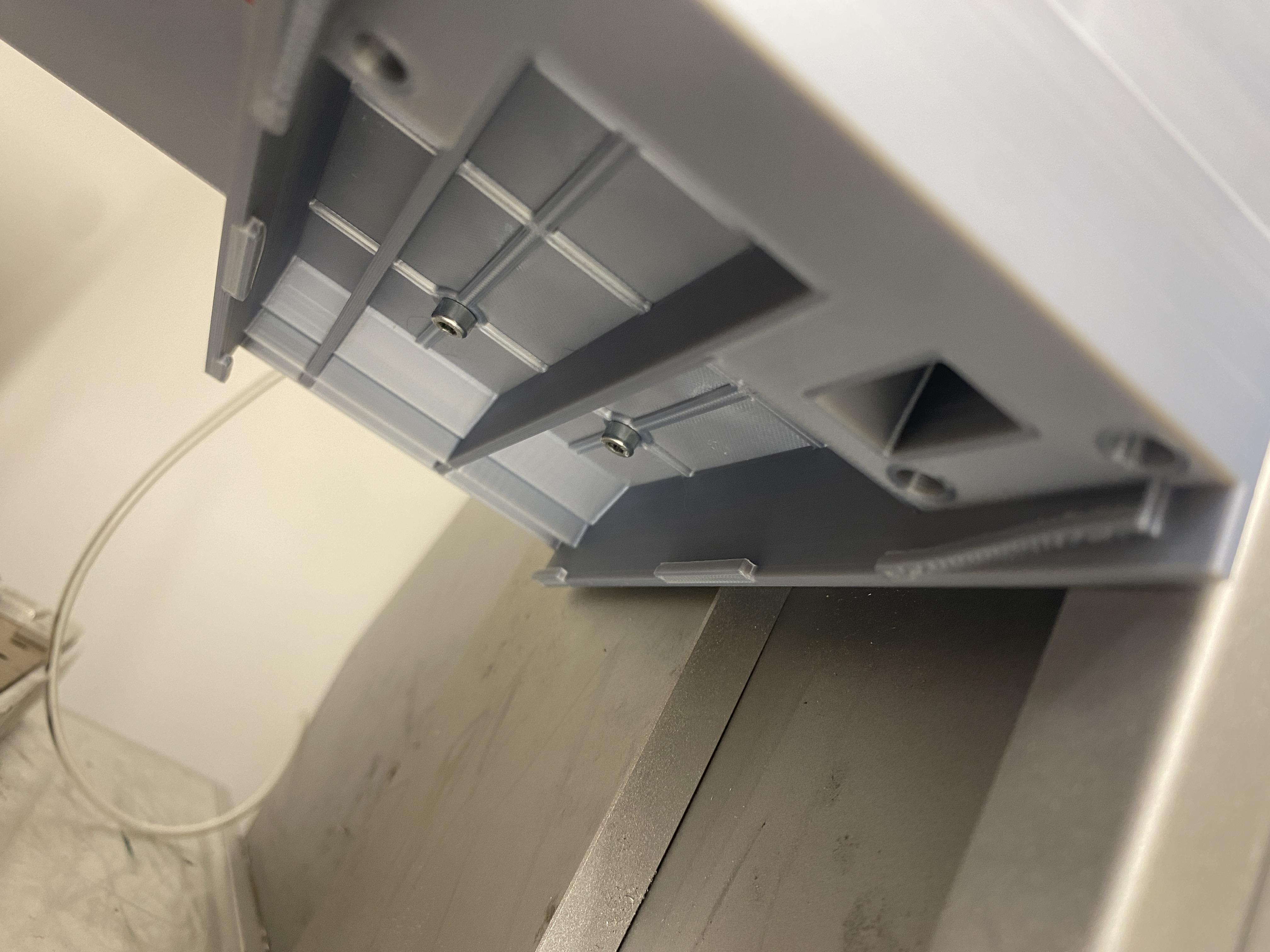
Line up the top cover pieces. Top Piece1 and one of the top center connection pieces will use the vacuum hose clip mounting pieces to hold them in place. Mark and drill/tap the mounting positions for M3. Again, make sure to check what is below where you are drilling to prevent drilling into any wires/internal bits on the machine.
Install the pieces with M3 button head screws, using the washers as needed.
Reinstall Wiring
Reinstall any wiring you removed in earlier steps.
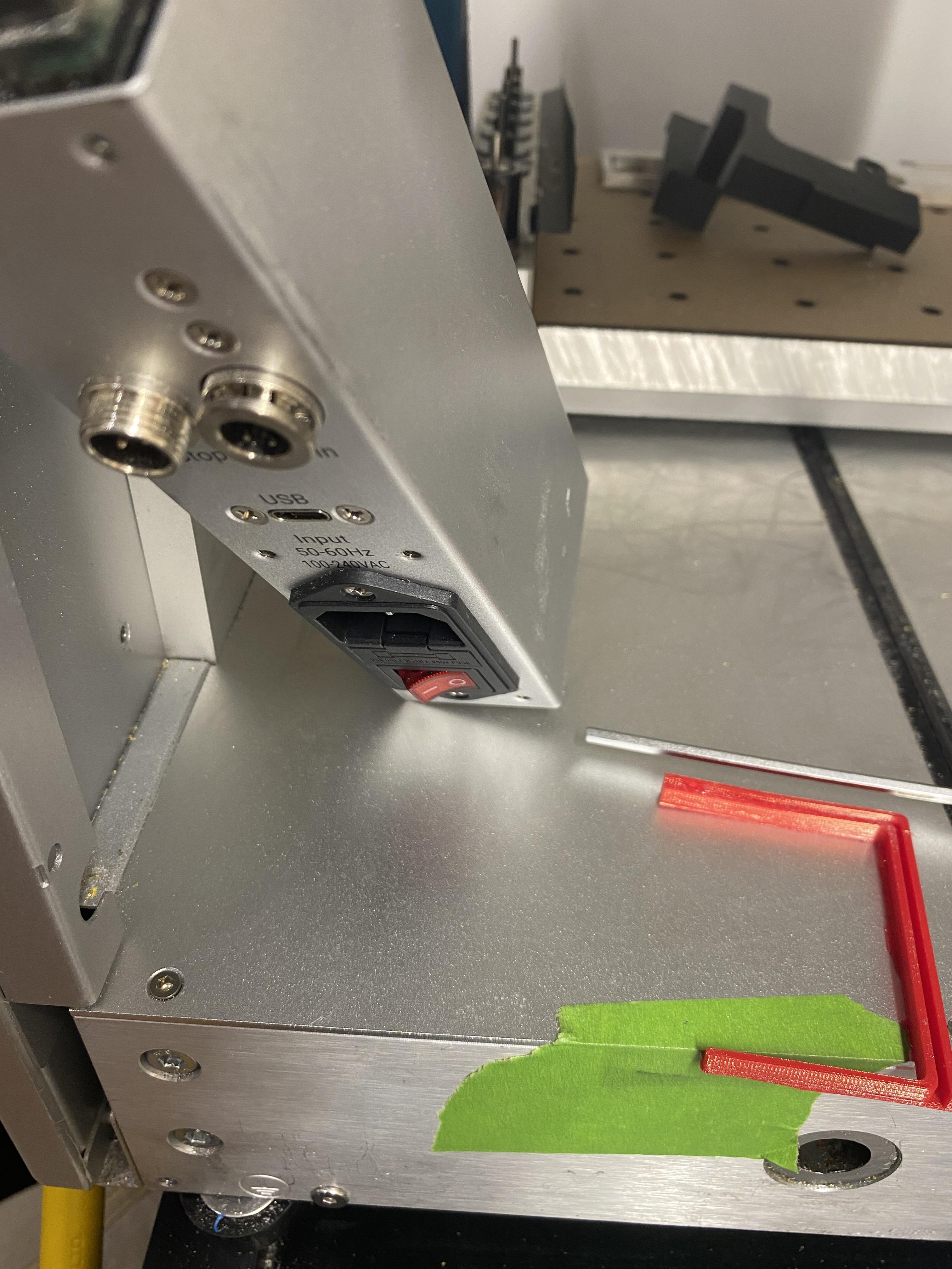
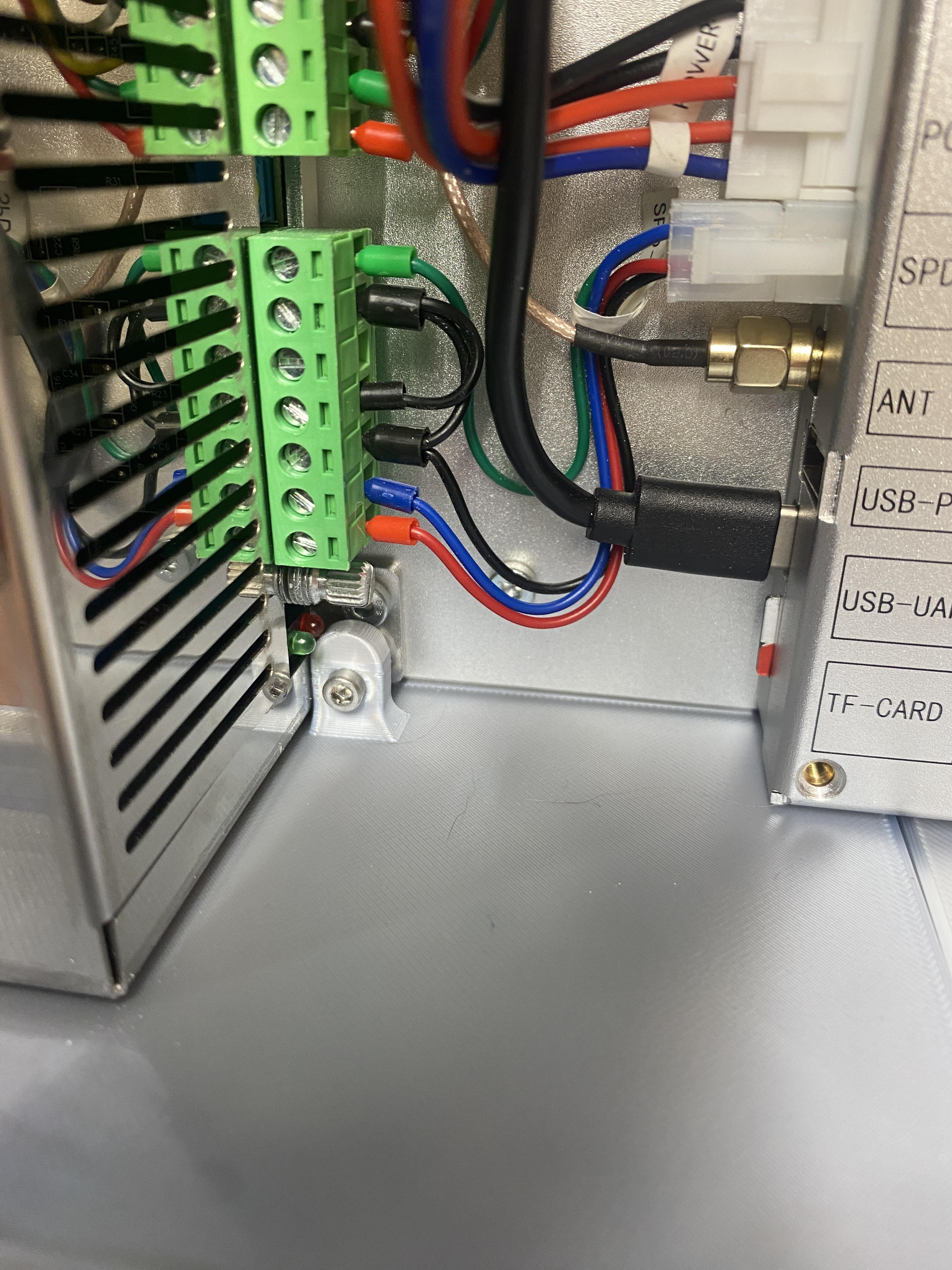
Install Power Side Grommet
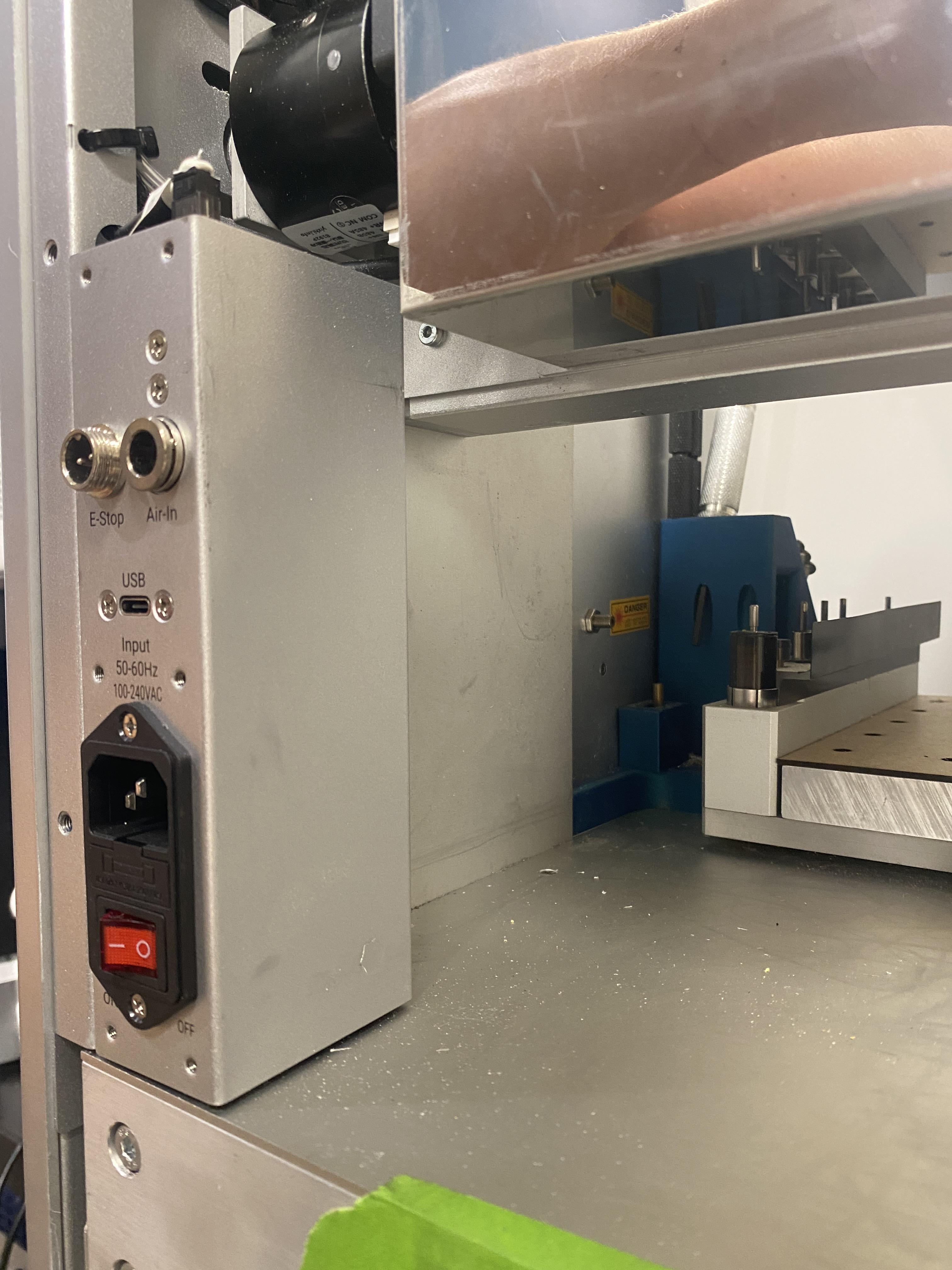
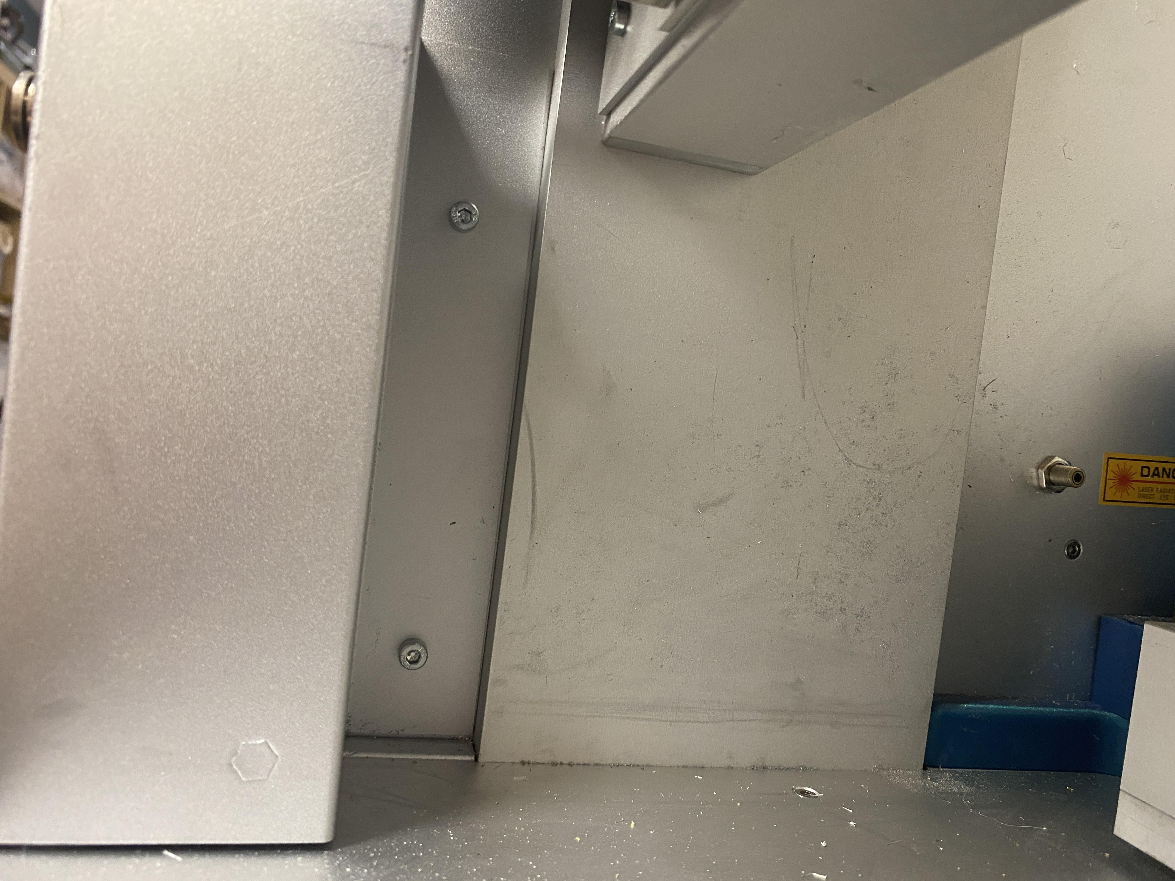
Remove the power connection panel with the two bolts hidden behind the part.
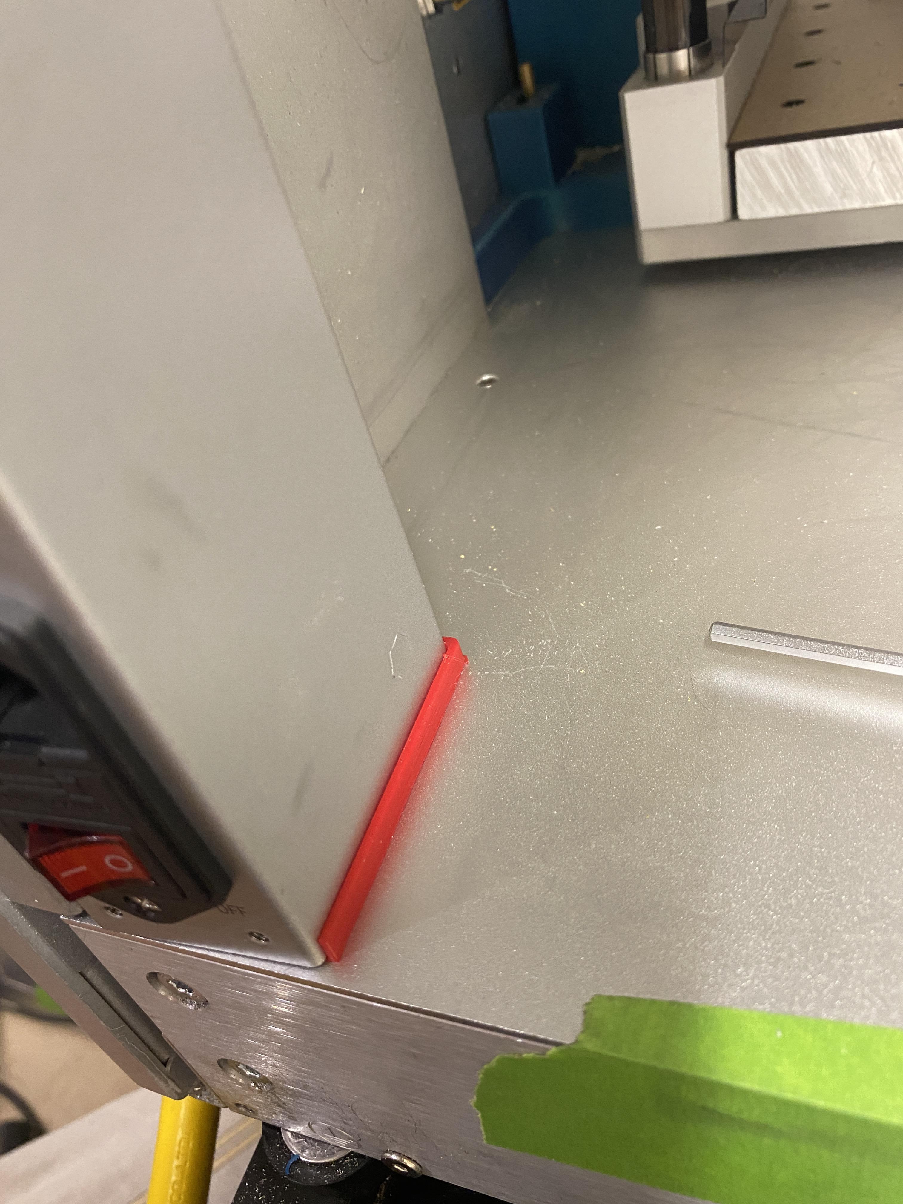
Slide on the power side grommet, it should fit over the bottom of the part nicely
Reinstall the power connection panel, pressing it down into the grommet.
Install Vacuum Chamber and Back Isolation Pieces

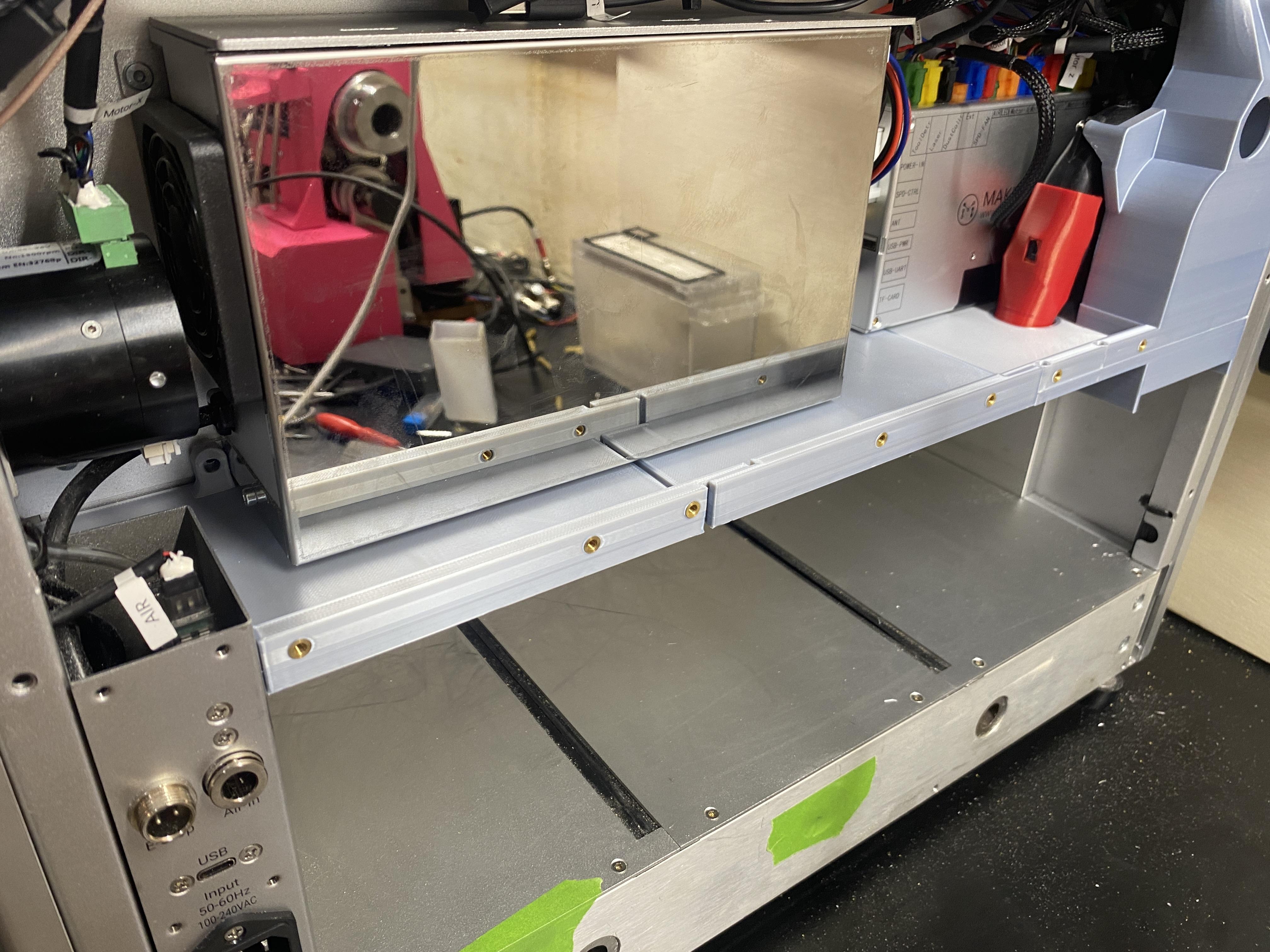
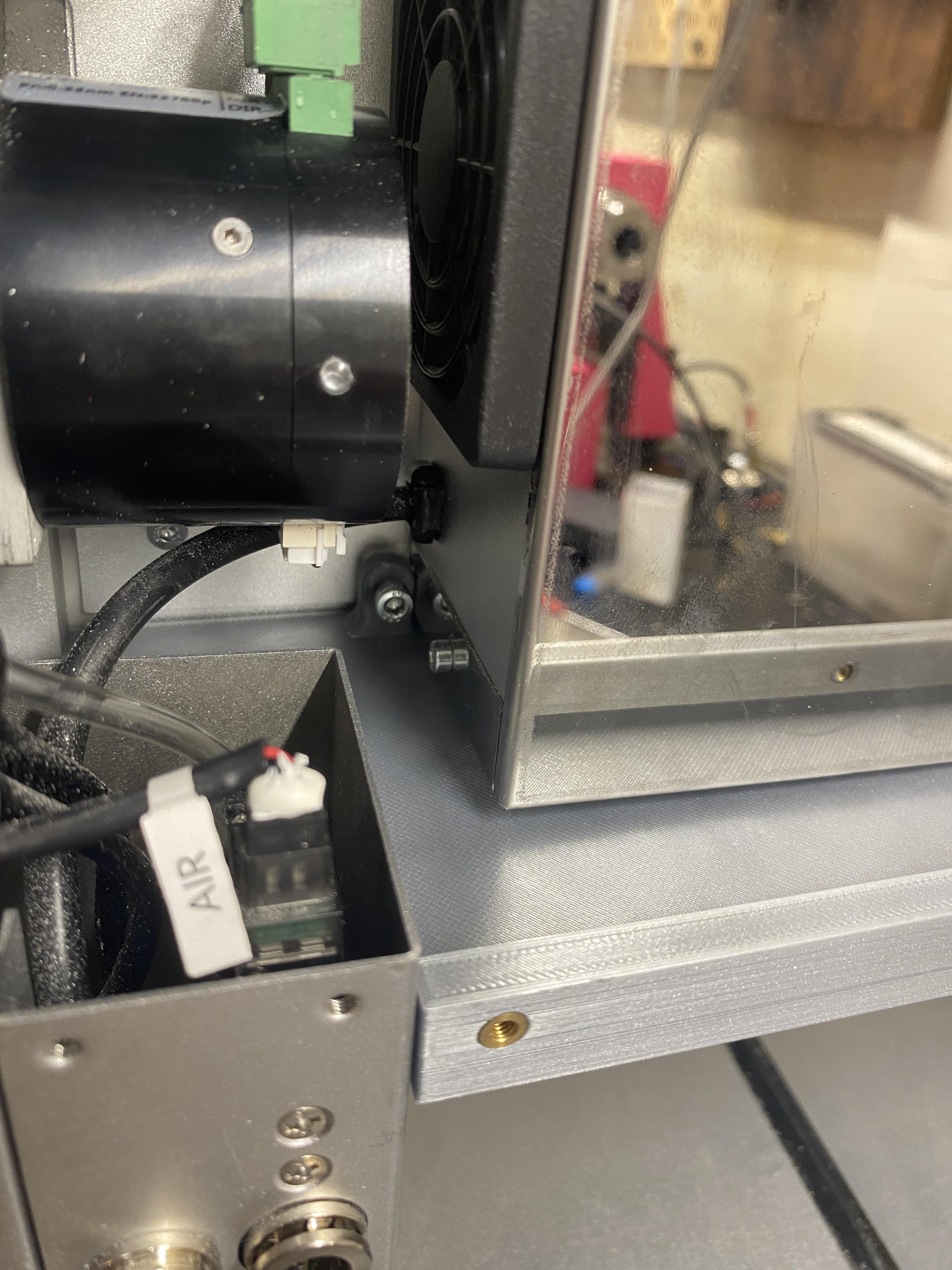


Install the vac chamber by plugging it into the main board, sliding it into position and using the three existing mounting hole positions to secure it in place.
Slot the Electronics protection panel pieces together lift them into place. The center piece will go above the vac chamber bottom piece.
Use the two power supply mounting positions to lock the pieces into place.
Something I have found helpful is to use some double sided tape along the front edge of the cover pieces where the connect to the bottom of the x axis gantry. They will hold in place fine without it, but the double sided tape provides a further attachment point.
Reinstall the Lid
.JPG)
Reverse the process of uninstalling the lid by gently placing it in the close position, making sure to align the aluminum hinge piece with the top of the machine. Install the two bolts then open the lid and install the gas pistons by attaching them at the base, lifting the lid past the normal open position, placing the ball end into the holder and tightening down the set screw gently.
Then plug the lights cable back into the main board.
Drill and Reinstall Back Panel
Drilling holes is not strictly necessary, but it will provide a better seal and help prevent any potential drooping of the printed parts over time.
Follow the attached drill guide to drill 4.3mm holes (4-4.5mm holes are fine) into the back panel.
reinstall the back panel with all the bolts removed at the very start of this process and use some M3 button head screws to attach the back panel to the isolation pieces.
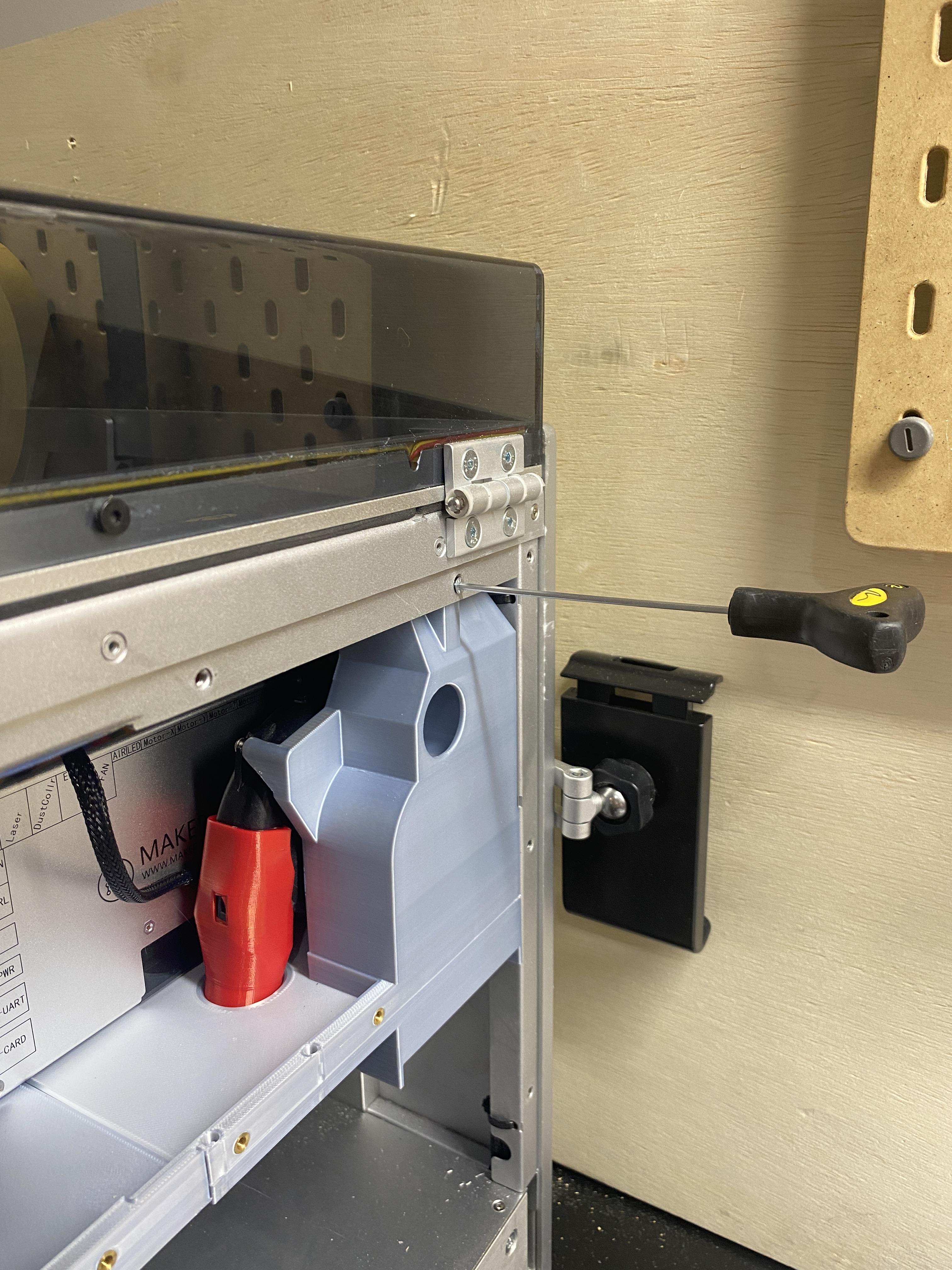
Install Vacuum Grommet and Vac Hose
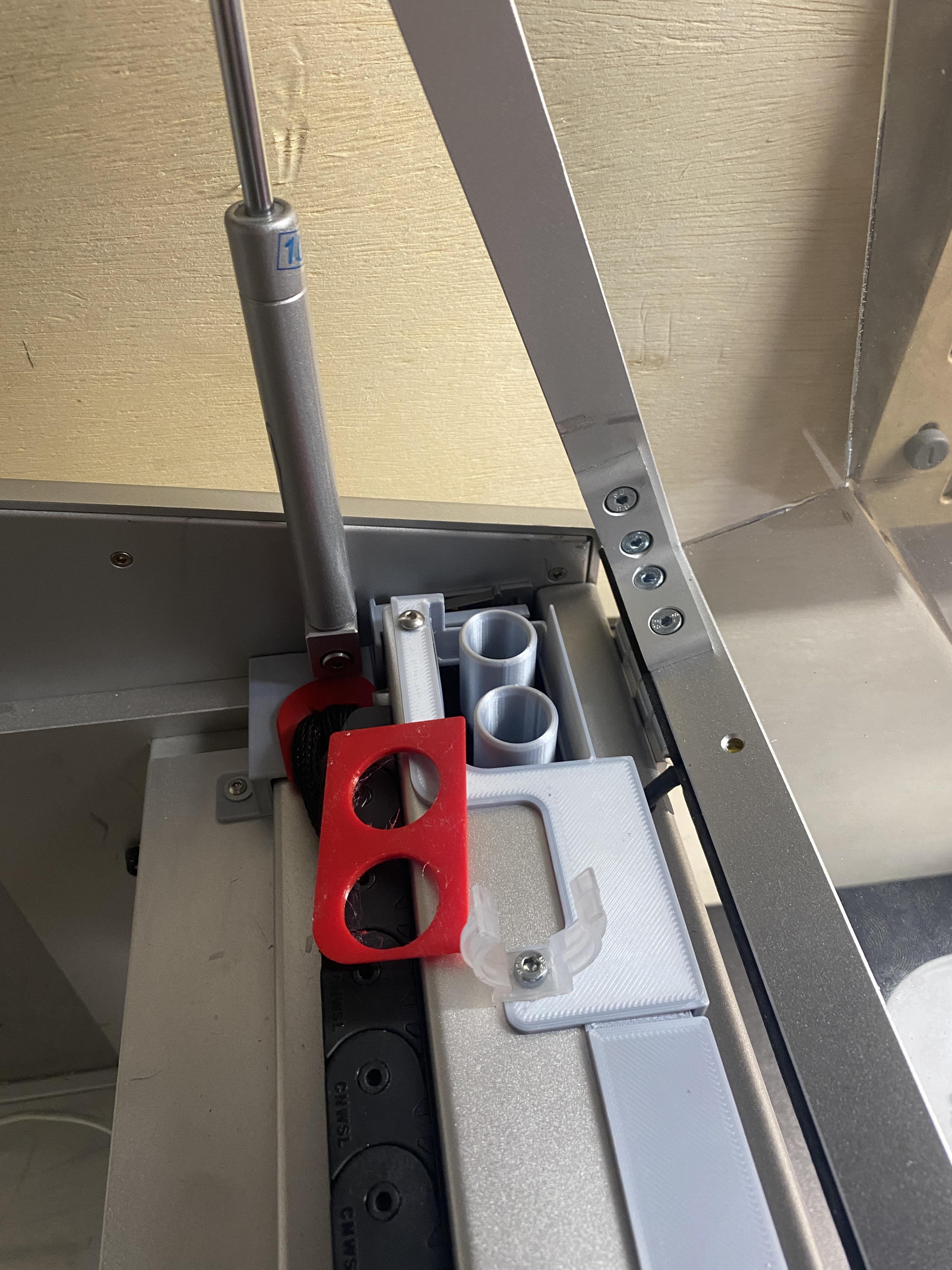
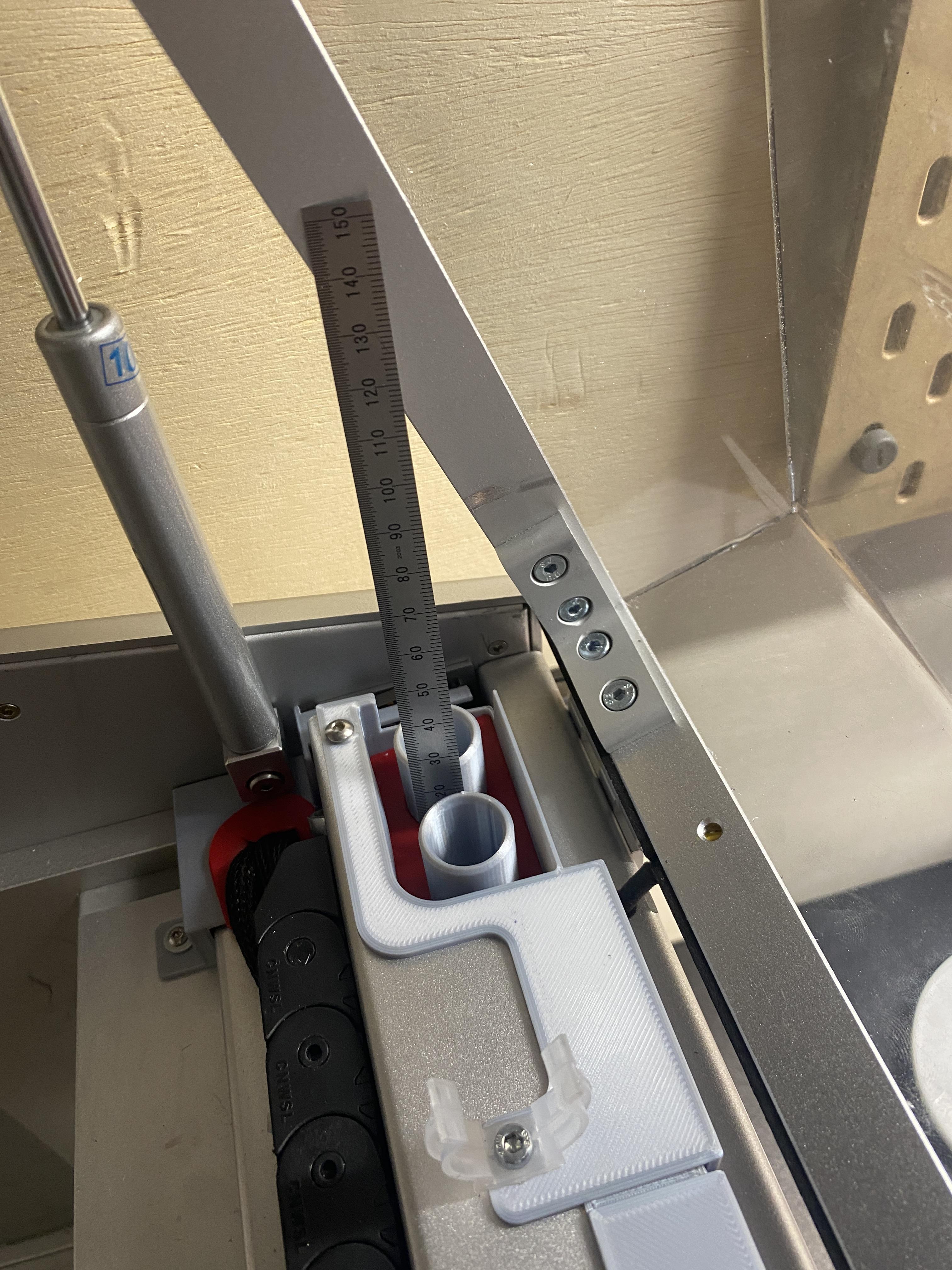
On the top of the machine, install the vacuum grommet with the smaller stepped side down. I find a machinist's scale useful to press it all the way down to the bottom of the printed part.
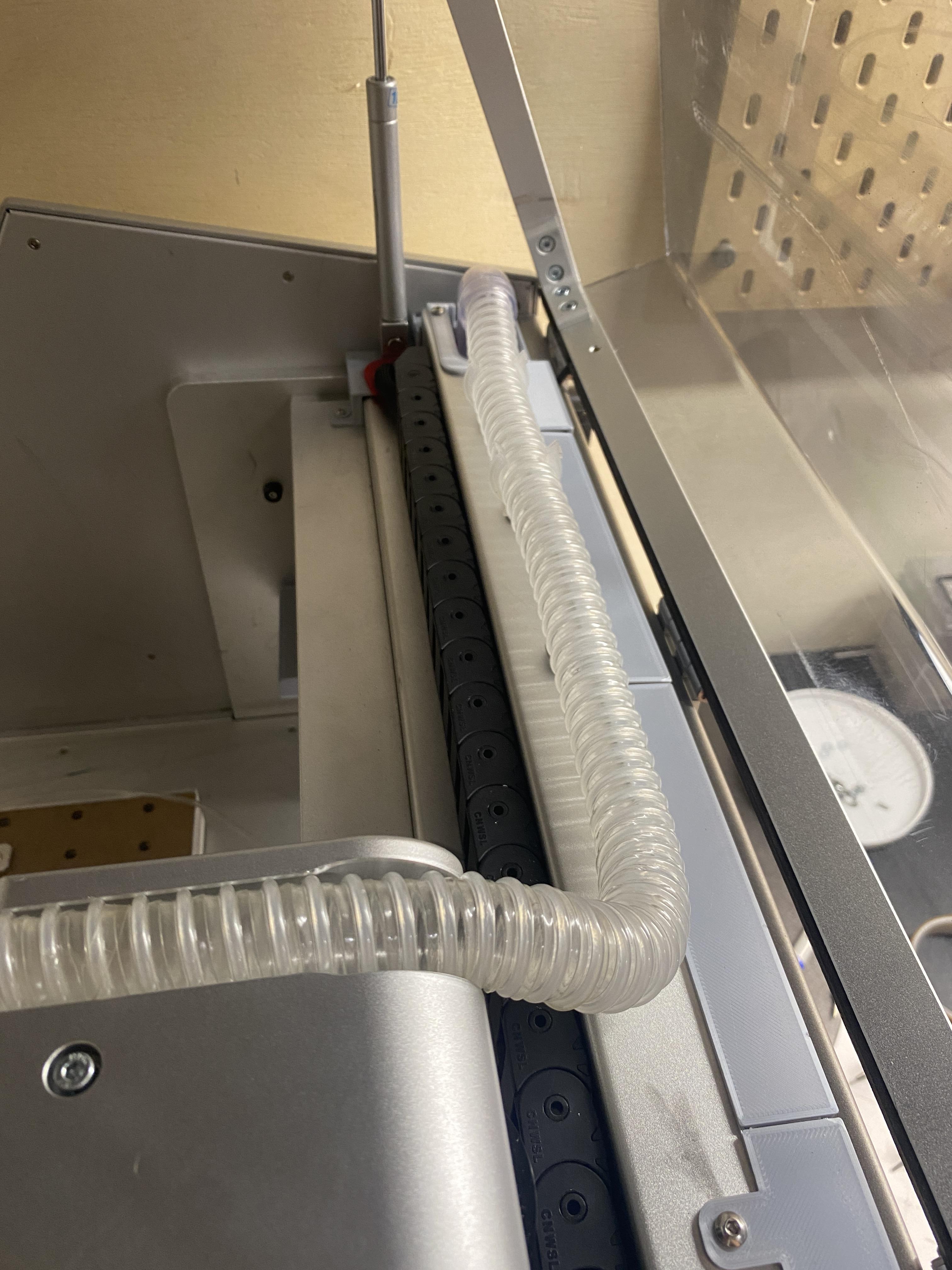
Reinstall the vacuum hose as it was originally installed
Install X Axis TPU Pieces
.JPG)
.JPG)
.JPG)
.JPG)
.JPG)
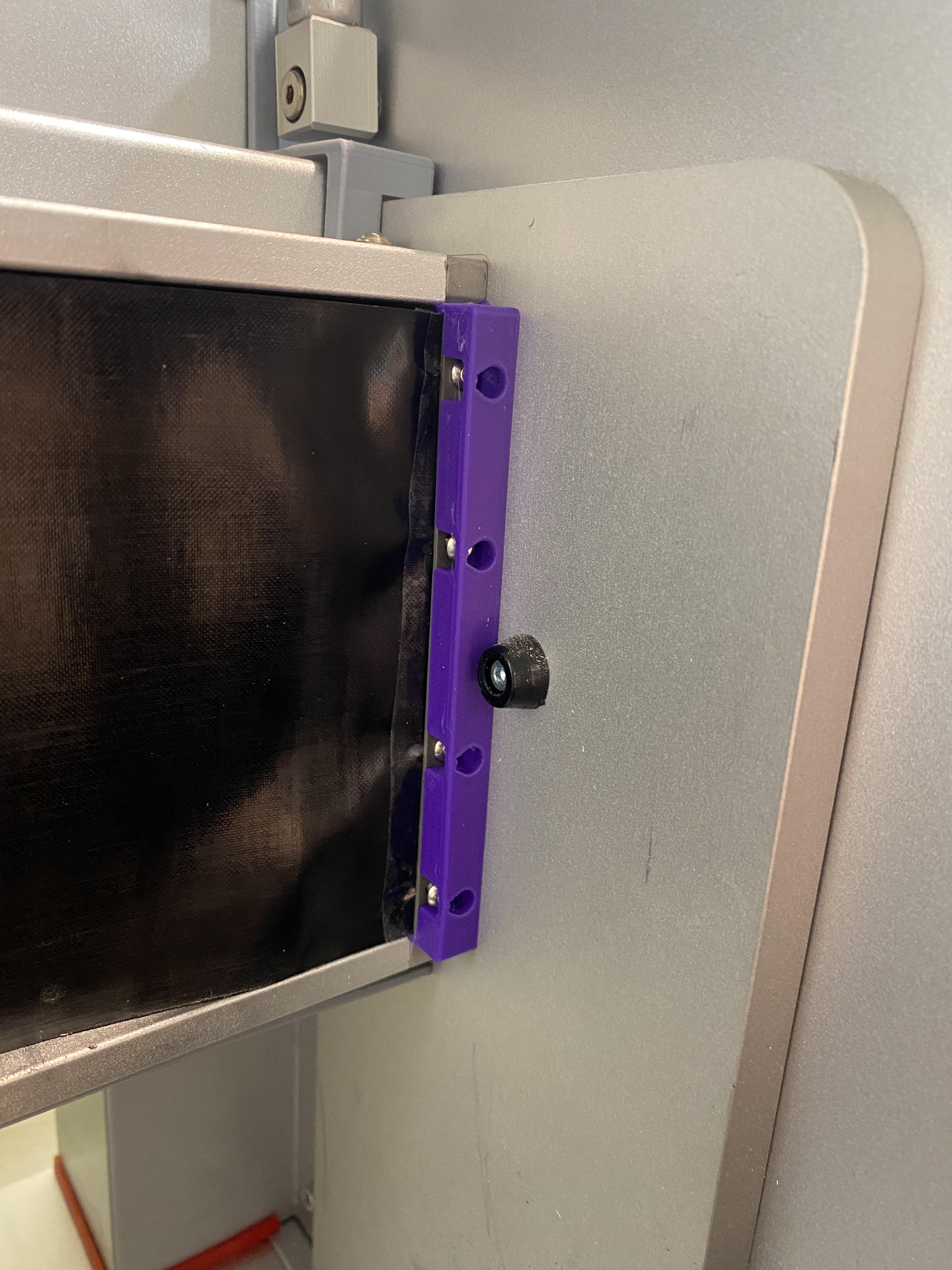
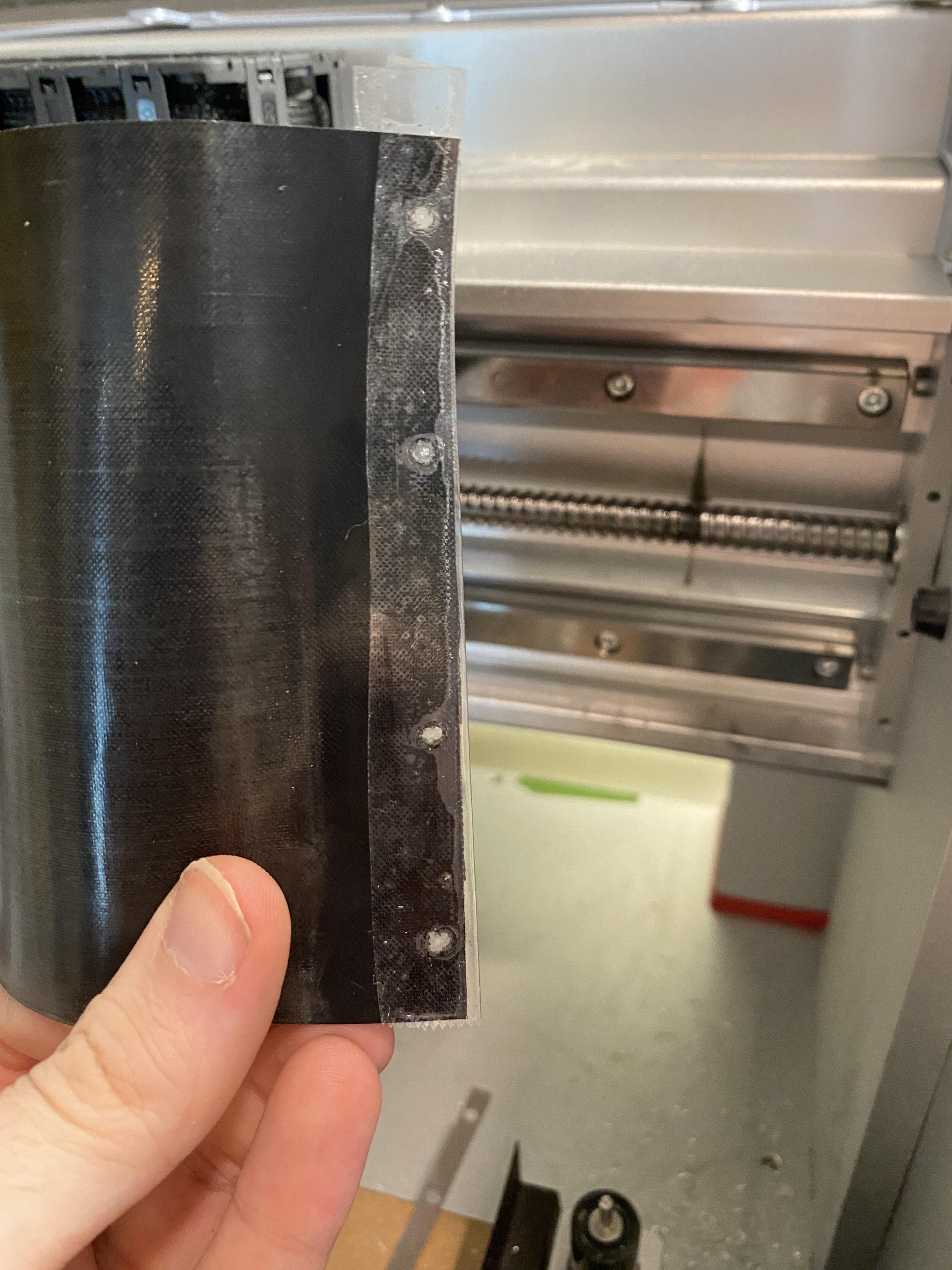
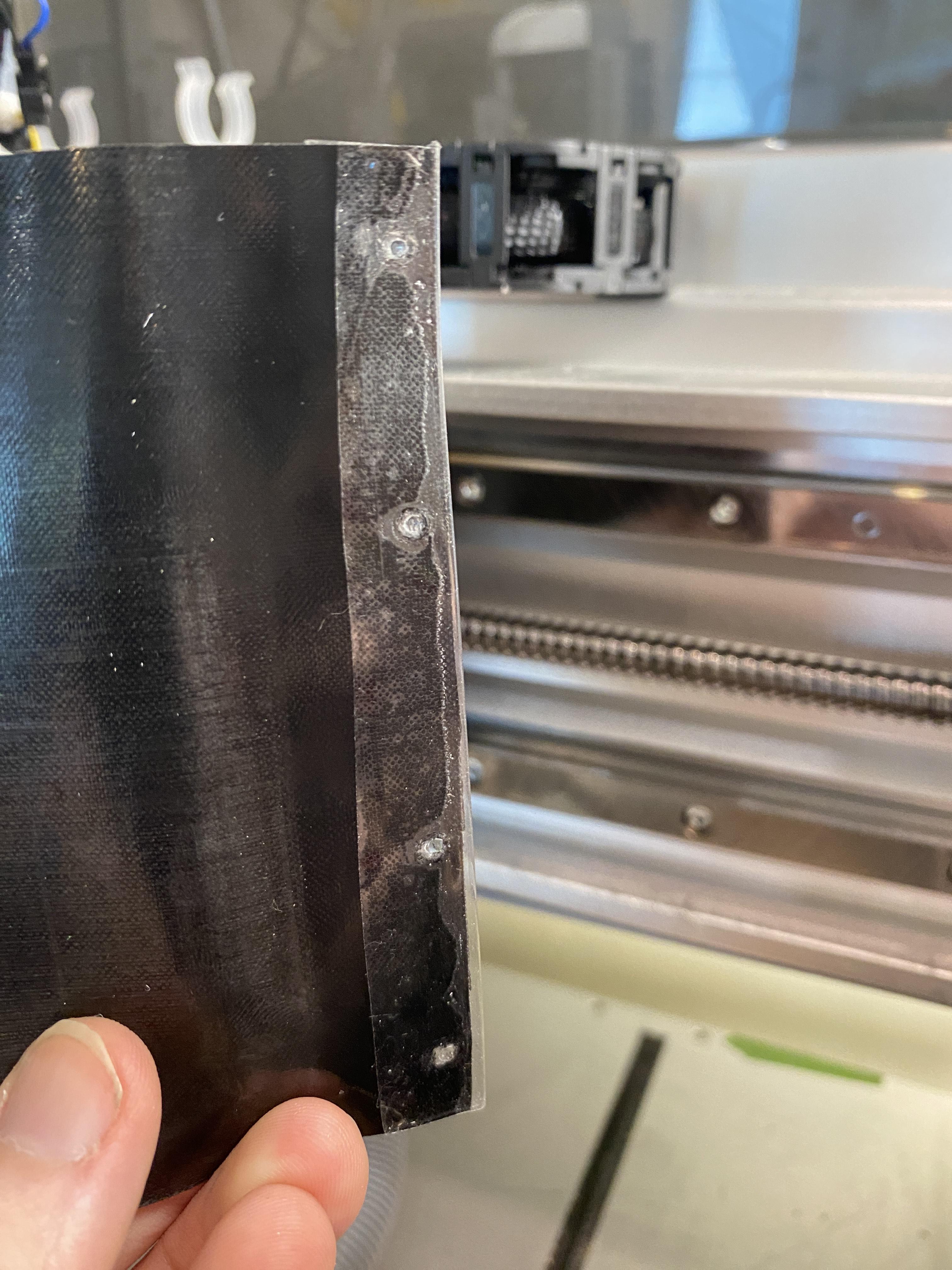
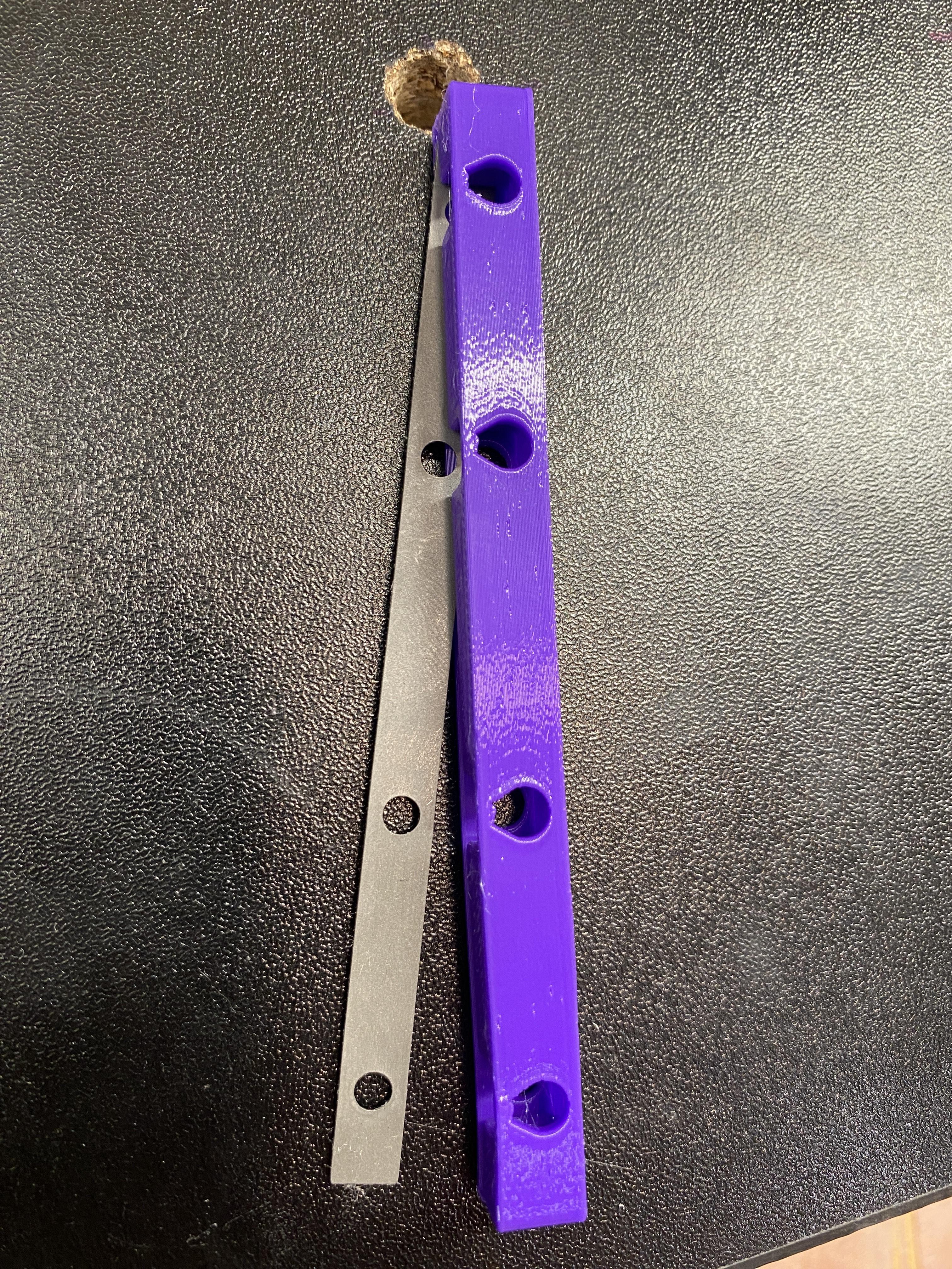
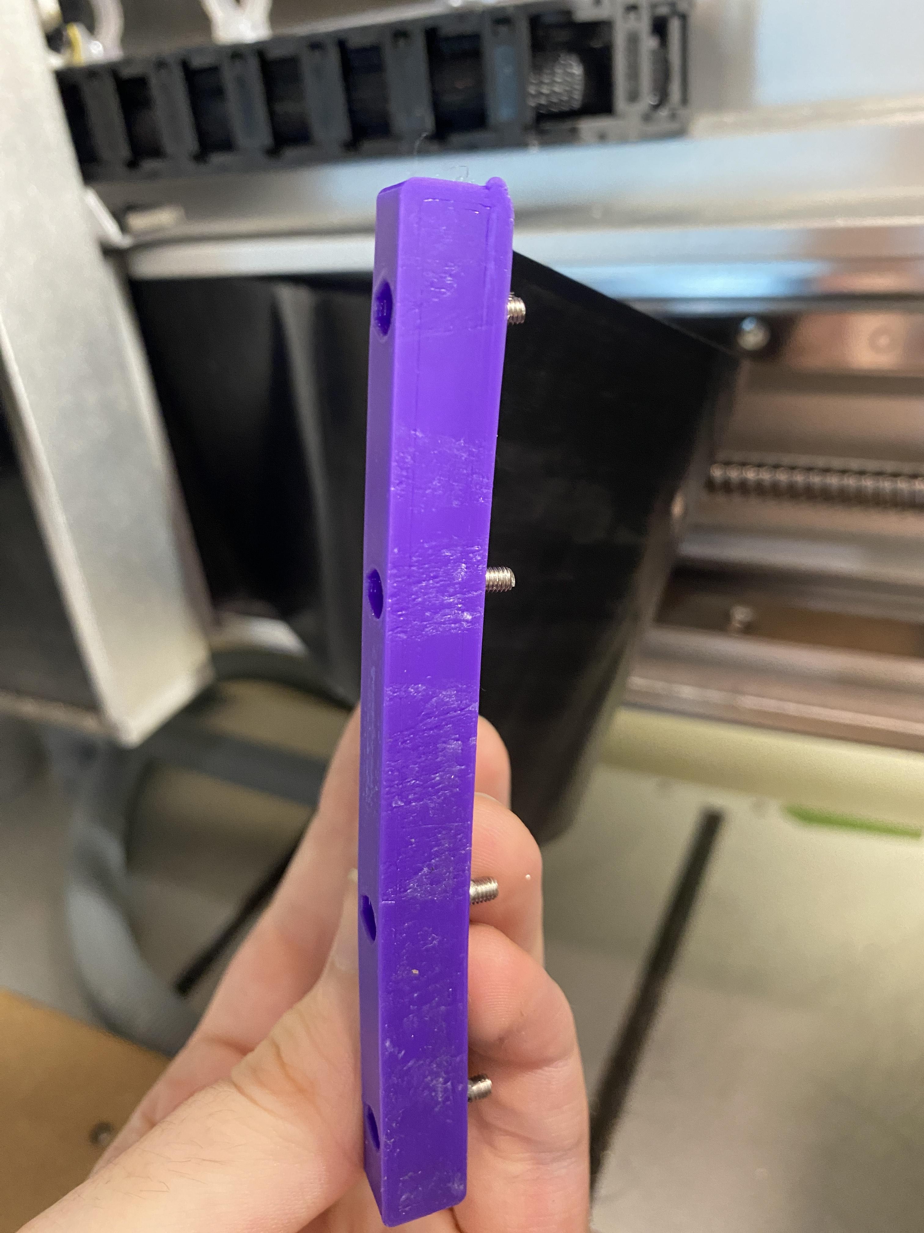
Uninstall the side cover for the x axis. I reinforced the ends of this part with shipping tape and a small hole punch as mine was fraying around the screw holes.
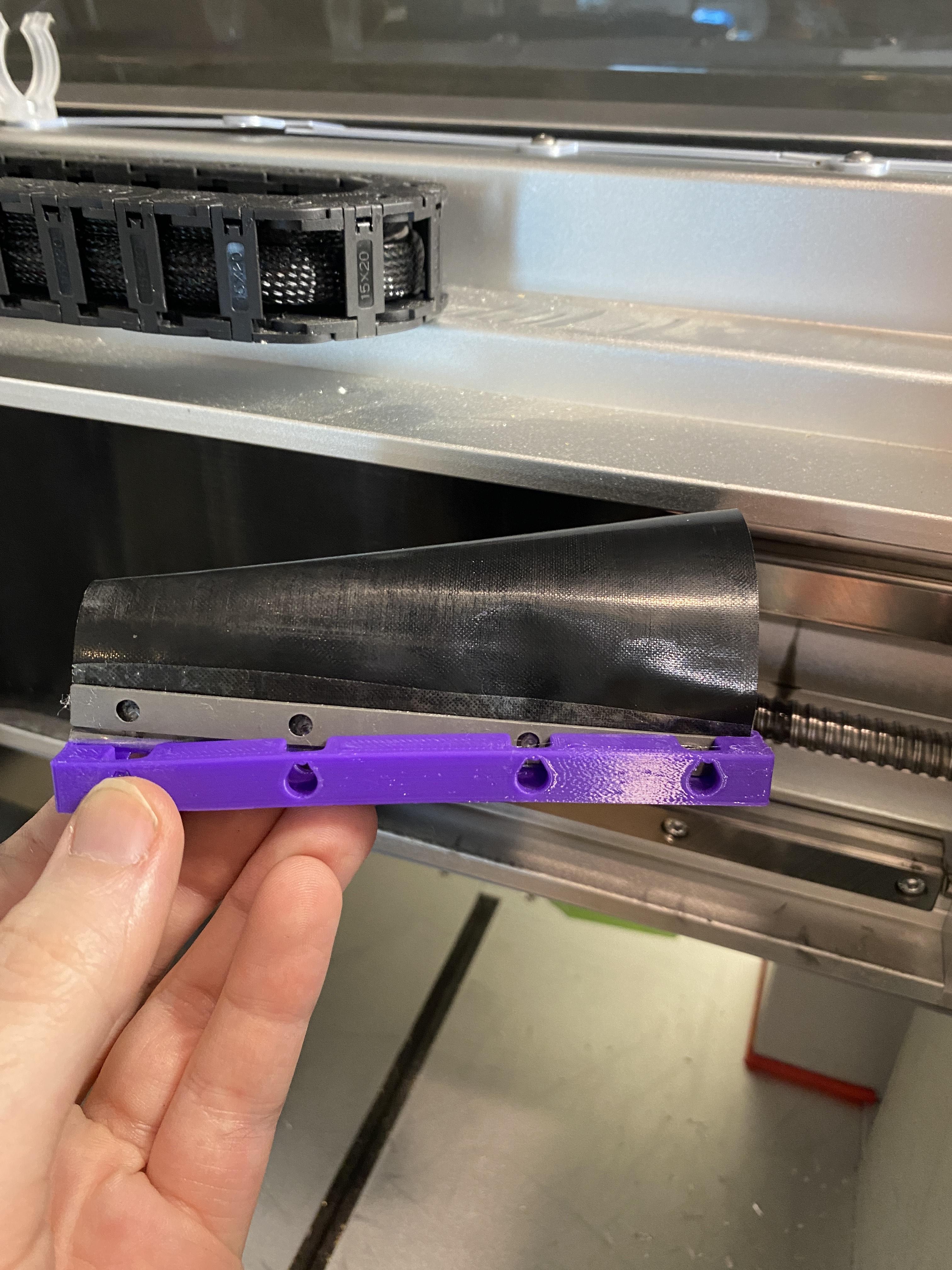
Using the metal piece from the cover to help, press the end of the x axis cover into the small slot on the 3d printed piece. You want the cover on the thin side
Press 4 m3 button head screws through the holes on the top of the part and through the metal and cover piece. They should hold in place
Reinstall the part onto the machine. Now when you remove the x axis cover the bolts are captive and the cover is much less likely to fray.