Carve Custom Wooden Game Pieces! ♘♖♕ ($12 CNC Upgrade)
14111 Views, 115 Favorites, 0 Comments
Carve Custom Wooden Game Pieces! ♘♖♕ ($12 CNC Upgrade)

Hi, I'm Caleb, I'm a student at the University of Texas @ Austin studying Mechanical Engineering.
Almost 2 years ago now I built my CNC (MPCNC) for about $600 dollars. It has been a super great experience that I highly recommend for any aspiring engineers like myself. I have racked up 1000's of hours cutting time over a 100's of projects. It has served me well and allowed me to do many wood projects that I never expected I would be able to do.
Recently I have wanted to expand the capabilities of my CNC router even more to be able to do projects around a rotary axis. My main inspiration for this project was to make a custom set of chess pieces for my brother. In this instructables I will show you my budget hardware as well as the process I invented to carve rotary objects with basic, free CAM software.
What You Need
)
Tools: CNC machine, Lathe (a normal wood lathe is nice for preparing stock), 3D printer (for printing parts)
Hardware: Nema17 stepper motor (with wire), Coupler adapter
Software: Fusion360, Blender, Scorchworks gcode ripper (not really needed)
Consumables: Wood (maple and mahogany)
Impoverished-Man's Rotary Axis
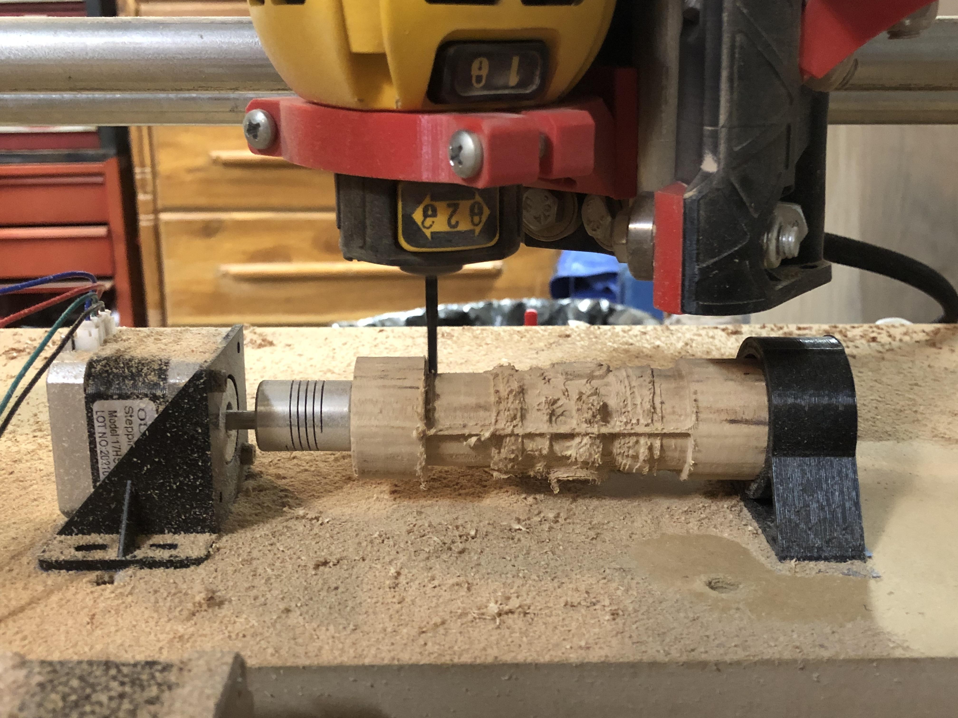
As you can see above, I didn't want this project to be too expensive so I made all my cuts with a setup that was only about $12. All you need is a spare nema stepper motor and a coupler, both of which I actually already had laying around from other projects.
In this version it is still a 3-axis machine where instead of the y-axis I have a rotary axis. While an actual 4th axis is achievable physically and in firmware, it is not necessary for things such as busts or chess pieces.
To my understanding, this rotational axis is called a "rotary axis" because is not meant to spin at a high constant rpm. While CNC lathes also spin, they use lathe tools from the side while rotary axis uses endmills and cut from the top. Anyway, I will call this a rotary axis.
Rotary axis are not a new thing even for hobby CNC machines. There is some information online such as from this link from the V1 (MPCNC) forum. However, the hard part of adding another axis is the gcode generation. The method I use to create gcode using blender and Fusion360 is something I have never seen done before online! (although I could be wrong). Using this method you can make complicated objects such as chess pieces without any expensive software!
Hardware (lets Not Break the Bank)
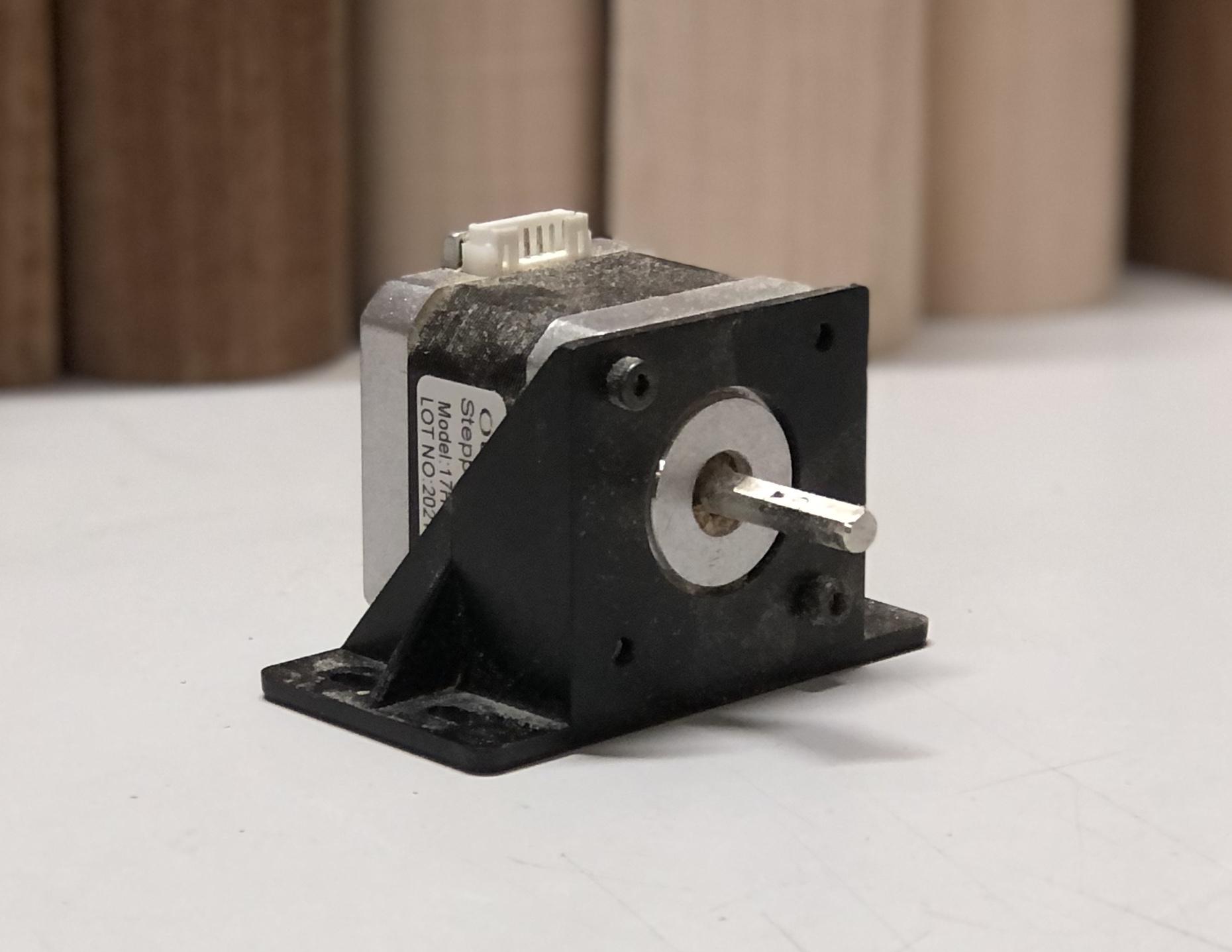
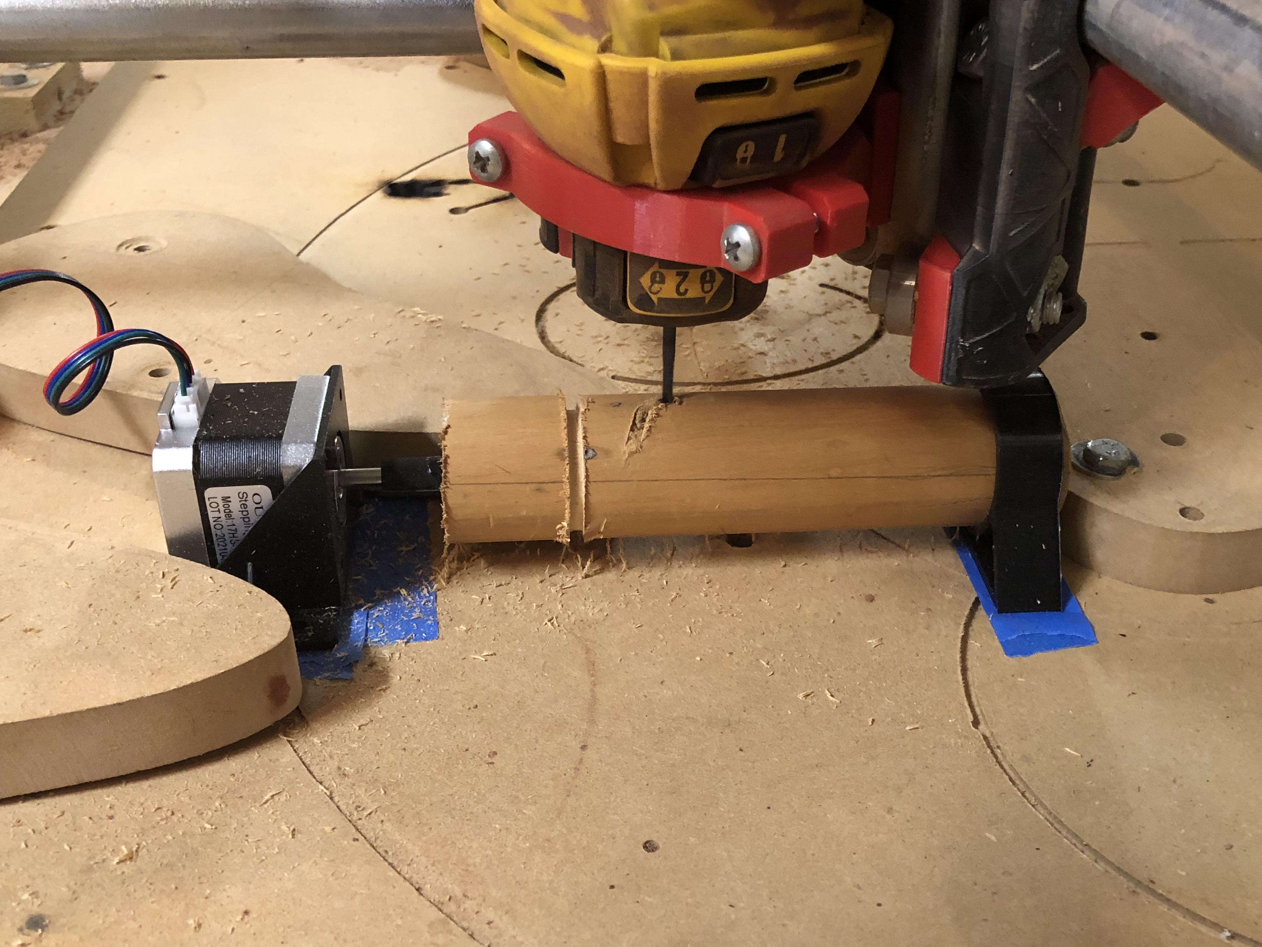
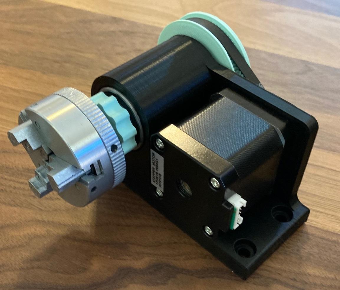
This is really pretty easy, you just need to find a way to attach the motor in a secure way to your CNC. There are many ways to do this; start with mounting your motor on something. The particular motor I had came with a mount but you could easily 3D print one.
Next you need to attach it to the table, for my impermanent version I just used blue tape and super glue. With some extra clamps this was rigid enough to get the results you see. A better way to do this would be to use screws or bolts or even just better toe clamps.
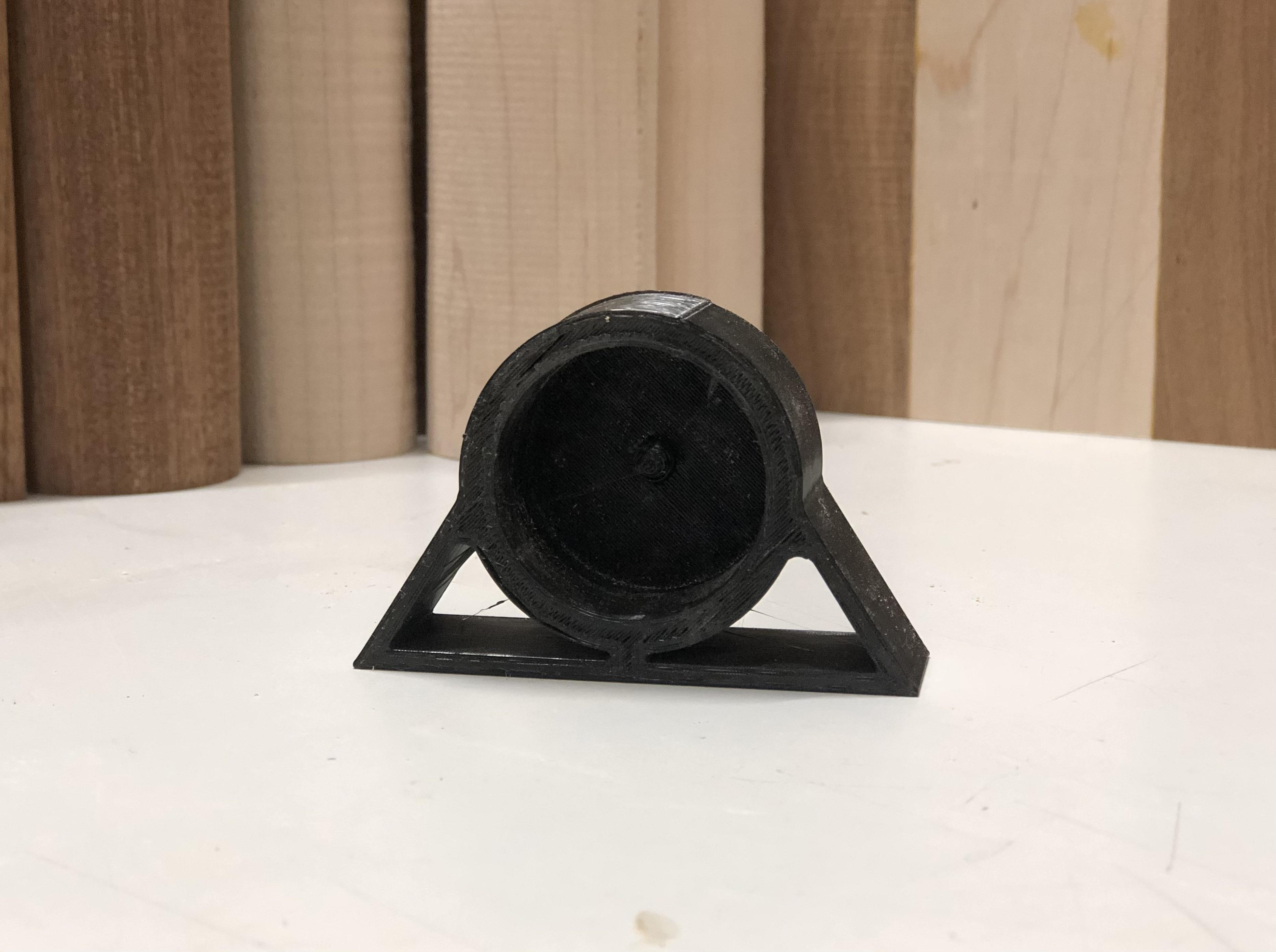
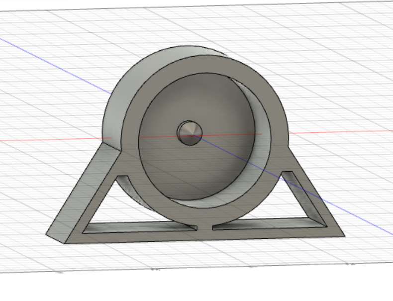
***Almost as important as the motor is the tailstock.*** The tailstock is the piece on the other side of the stock that keeps the wood straight and prevents it from deflecting. I just 3D printed a quick tailstock with the center height being the same height as the center of the motor. I also added A POINT ON THE MIDDLE of the tail stock to push into the wood. This point was really useful and worked much better than when I used a tailstock without it. Again, I used blue tape and superglue to attach it to my spoil-board.
Attach Wood
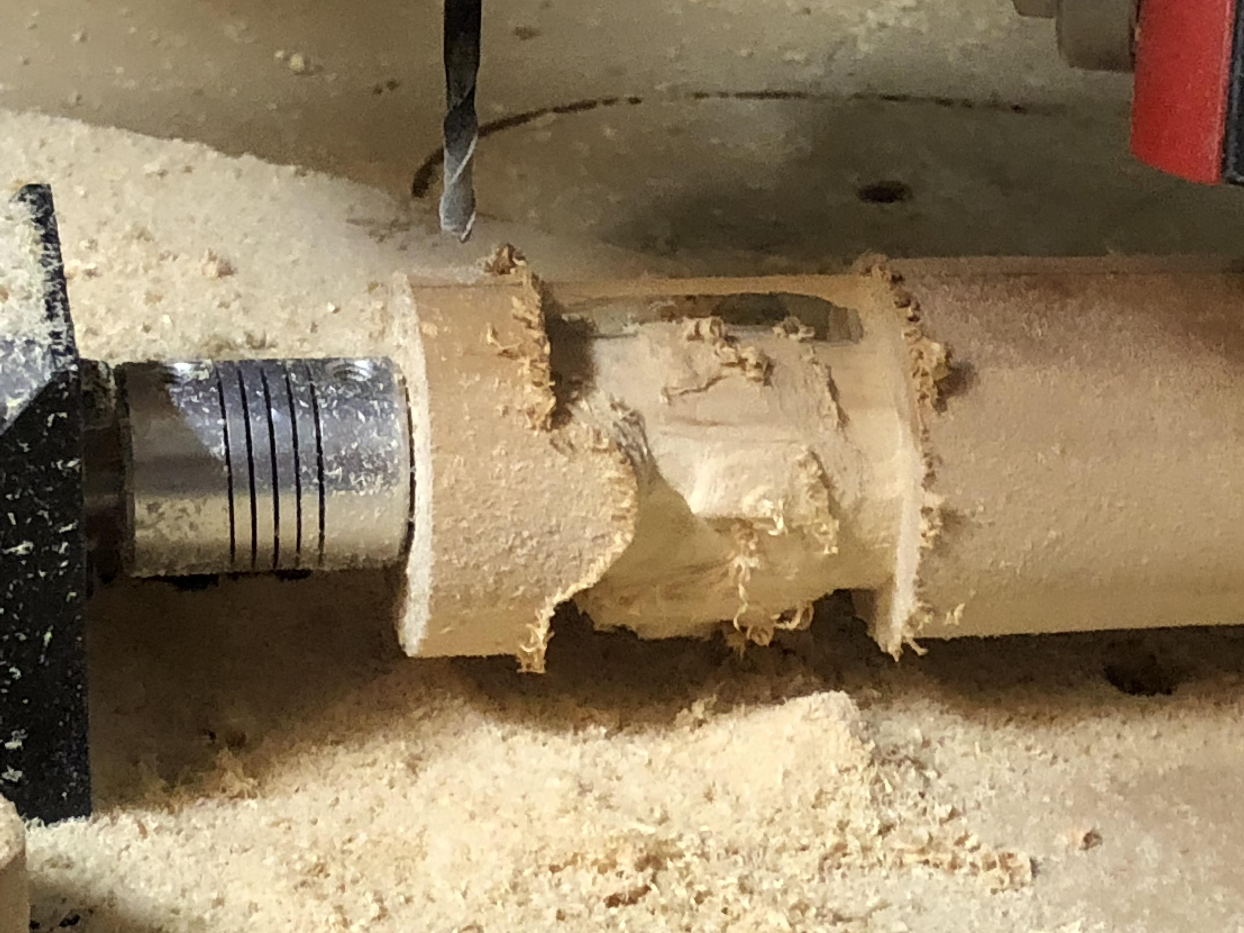
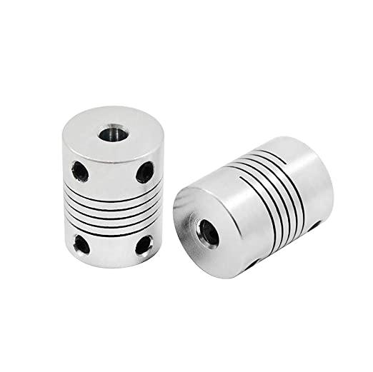
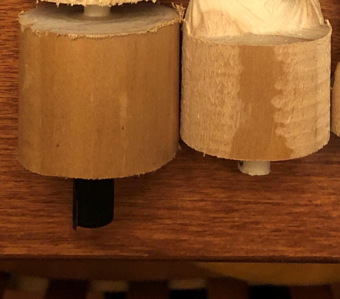
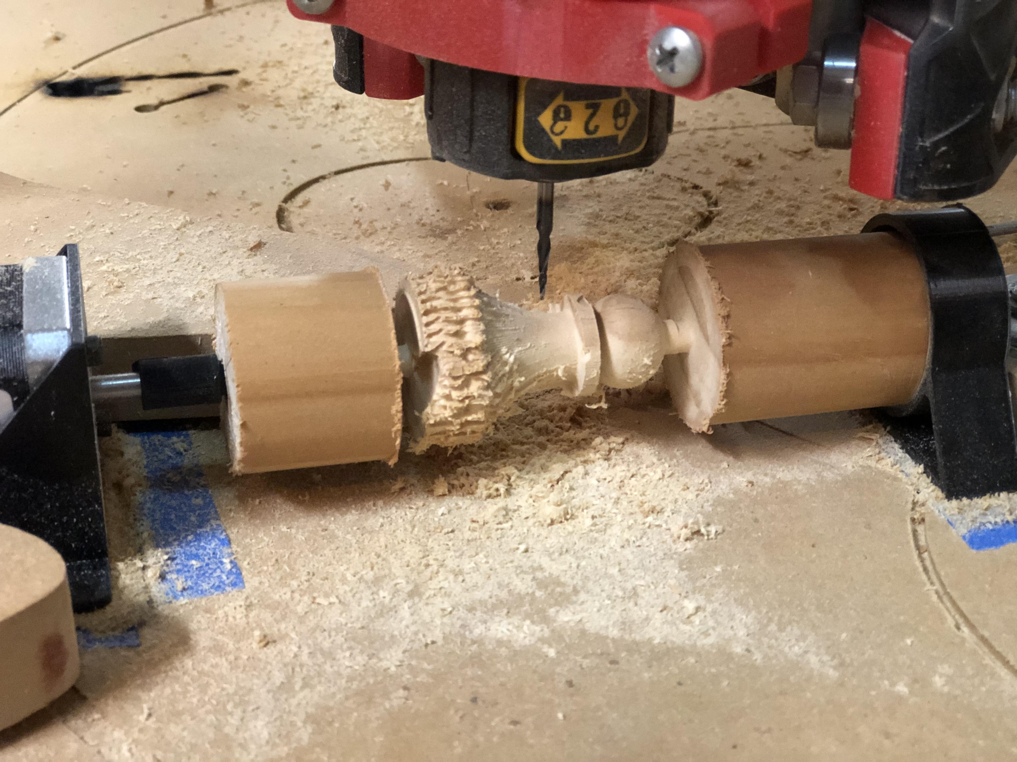
Next, I needed a way to attach wood to the motor. I tried a few different methods but the one that worked the best for me was using a coupler with grub screws like you would see in between a motor and a lead screw.
The main limitation with this method is the need for the stock to have a tenon. There are a couple ways of adding a tenon onto the end of wood. I have access to a lathe which I used to turn the tenon but it would also be possible to drill into the end and glue a bolt or dowel. Whatever method you go with it just has to be the right size to fit into the coupler and be strong enough to not flex or break under some force.
(ALTERNATE Hardware + Drop Table)
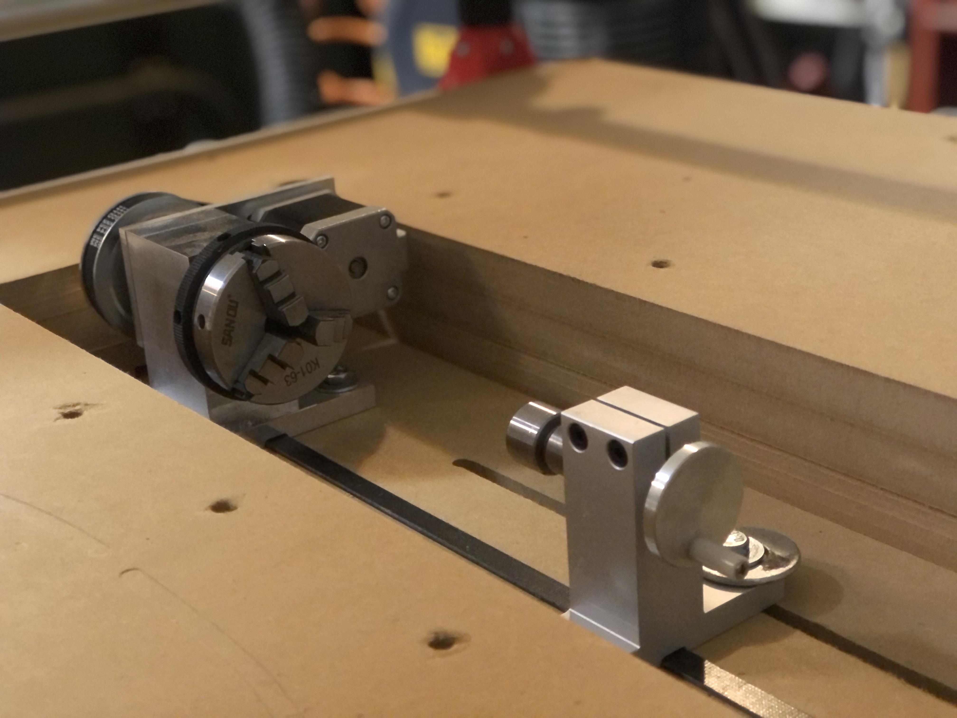
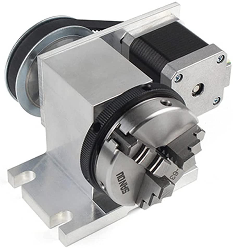
After making this project I will admit that I invested some time and money into a SLIGHTLY less janky setup. I bought the setup with a tailstock for about $160 that has a couple benefits. It's rigid because it is metal. Its 4:1 gear ratio belt provides for extra torque. It has a real chuck for more versatile stock holding. It has real tailstock with reach.
In order to make this work on my table with just a few inches of z-axis travel I also decided to add a drop table. Using my CNC to make sure everything was square I cut out a hole in my main board with countersunk bolt holes and an alignment groove along the (to be disconnected) y-axis.
If you want a slightly better setup without shelling out the money to buy a rotary axis there are also 3D printable options such as this or this. Personally, I don't think these are worth the time when they would likely still cost at least $50 to make and lack some rigidity for routing.
Electrical Connections
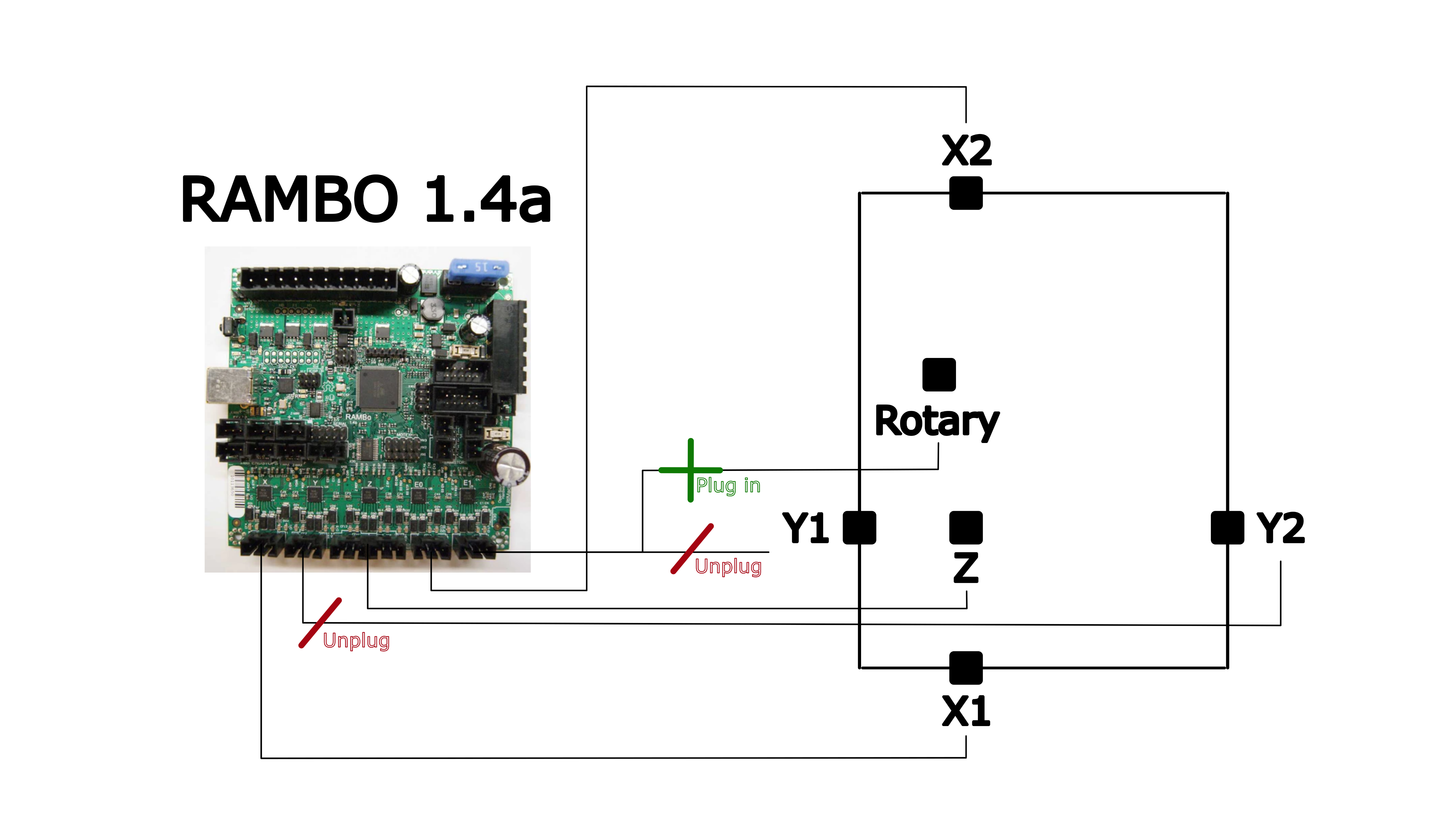
Since I'm just replacing the y-axis there is really not a lot of need to modify things electronically. I made no changes to the firmware. The only thing I am going to do is unplug both y-axis steppers and plug in my rotary axis stepper instead. Make sure everything is POWERED DOWN for this. Unplugging the steppers while the board is powered can burn out the stepper drivers. (I have burned out five a4988 drivers in the last couple weeks, they're very fragile!)
If you wanted to add a real fourth axis this would totally be possible! It would require adding an additional motor controller and making some changes to add the axis into the firmware. A project for another instructable!
Software Nightmare
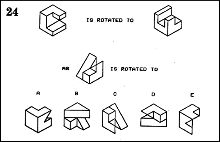
Congratulations! The hardware was the first half, now time to do harder stuff :) Thinking in 3 dimensions can be pretty challenging, take the quiz in the picture above for example. Likewise, thinking about the toolpaths even for a 3-axis machine can be complicated, and now we have a rotary axis.
The main difficulty in this project is generating gcode to use this beast. The problem is that most CAM software capable of generating 4 dimensional toolpaths is really expensive. For a hobbyist and a student like myself I tried to avoid paying for any extra software. Although a bit complicated, I did find a way to solve this problem using blender (open-source software) to assist.
Since the problem is the radial axis, my method involves converting the radial axis into a linear axis. By unwrapping the model around it's axis of rotation we can then generate flat toolpaths that essentially remap any movement in the y direction to movement in the rotary direction. After that there is just a short but crucial process of reassigning the steps/mm number in your firmware using a line of code in your gcode file. In the next few steps I am going to include more information detailing the process. If videos are more your speed I also do my best to explain my solution in the video at the top of this instructable.
Creating/Unwrapping Model

The process begins by actually unwrapping a 3D model around it's center and laying it flat. For this I use blender— the king of all 3D manipulation. Blender is free but it has a bit of a learning curve, watch my video with key-logger if you get stuck.
Import your model. Rotate and scale so that the back of where you are unwrapping is in the positive y-axis. Move the object so that the center is on the world origin (3d cursor). Dissolve faces from the bottom and top of the model if the geometry looks messy. Apply scale, rotation, and location. Open the text editor and make a new script copying the following code. Run the script in edit mode with one of the outer-most vertices selected.
import bpy
import bmesh
from mathutils import Vector
from math import copysign, pi

context = bpy.context

ob = context.object
me = ob.data

bm = bmesh.from_edit_mesh(me)
#bm.from_mesh(me)

v_r = bm.select_history.active
r = v_r.co.xy.length

assert(isinstance(v_r, bmesh.types.BMVert), "Select a Vert")
cut = bmesh.ops.bisect_plane(
        bm,
        geom=[f for f in bm.faces if all(v.co.y > 0 for v in f.verts)] + [e for e in bm.edges if all(v.co.y > 0 for v in e.verts)] + [v for v in bm.verts if v.co > 0],
        plane_no=(1, 0, 0),
        )["geom_cut"]

for g in cut:
    g.select = True


bmesh.ops.split_edges(
        bm,
        edges=[e for e in cut if isinstance(e, bmesh.types.BMEdge)],
        verts=[v for v in cut if isinstance(v, bmesh.types.BMVert)],
        use_verts=True
        )


# now "unfurl"

up = Vector((0, -1))
for v in bm.verts:
    co = v.co.copy()
    angle = -up.angle_signed(v.co.xy)
    if 1 + up.dot(v.co.xy.normalized()) < 1e-4:
        # meridian
        fv = sum((f.calc_center_median().x
            for f in v.link_faces)
                 ) / len(v.link_faces)
        v.select_set(True)
        angle = copysign(angle, fv)
    v.co.y = co.z
    v.co.z = co.xy.length - r
    v.co.x = angle * r


bmesh.update_edit_mesh(me)
Export the stl making sure to export the "selection only".
If the script above gives you an error, make sure that all of your faces on the top and bottom are dissolved. Then try offsetting the center of the object by a hair and applying scale before trying again. Last you can try to use the other method/code mentioned on the above forum after boolean subtracting a small cylindrical and rectangular cutout from the center of the model. You got this!
Generating Gcode (Fusion 360)
Now that you have the flattened model you need to generate gcode for it. Once again do this in whatever software you would like but I am going to use Fusion360.
Before we start the toolpaths though we have to import the model and scale and rotate it appropriately. You will want to position the model so that a move in the y direction correlates to the desired rotation (assuming your rotary axis is parallel with the x-axis). Scale it proportionally to the dimensions you would like that will fit in your stock.
Then, scale the model in the y direction to the length that corresponds with the outer circumference of your virtual stock. For example, if you set your origin 10mm above the center of your motor then the circumference at that point is 20π (C=2πr). So, you would scale your mesh in the y direction until it is ~62.83mm long.
It is a good idea to also make a box as virtual stock, this will help for visualization as well as setting the origin. Its z dimension should be how many mm above the center of the rotary axis you will set the origin and start the machine. This may just be the radius of the stock or you might want to leave some extra room for slop in the chucking of the wood and set it higher.
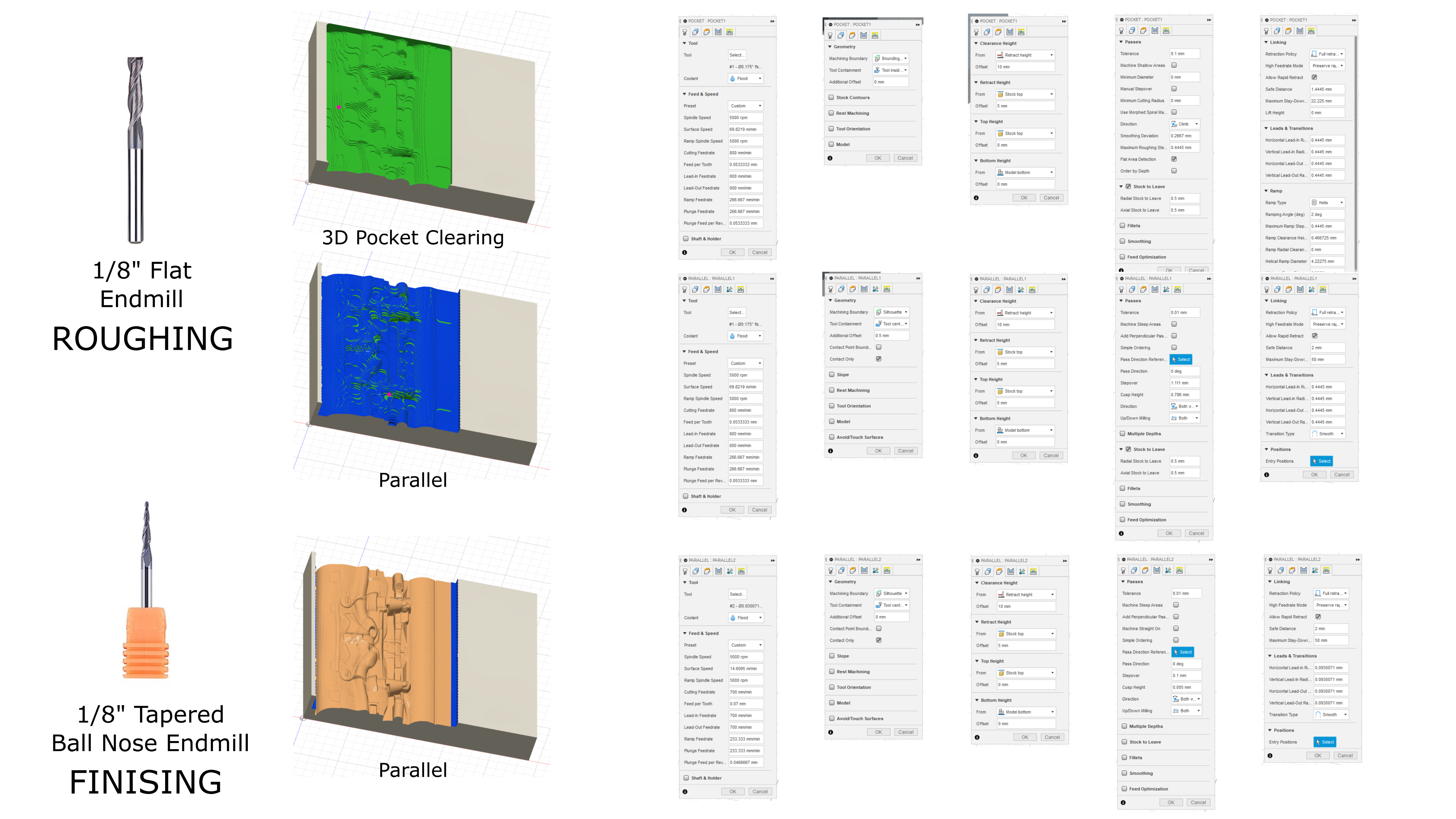
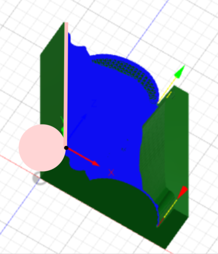
After you have made the mesh and virtual stock you need to generate gcode in the manufacturing tab. Do this as you usually would. For most bas-relieve-esque models personally I use a 3D adaptive or 3D pocket and parallel paths using an 1/8" or 1/4" flat endmill and an 1/8" tapered ball nose endmill. Above is a picture of my setup and settings if it's helpful. Make sure to put the origin at the top of the virtual stock the distance above the center of your motor that you are going to set the X0 Y0 Z0.
Making Gcode Usable
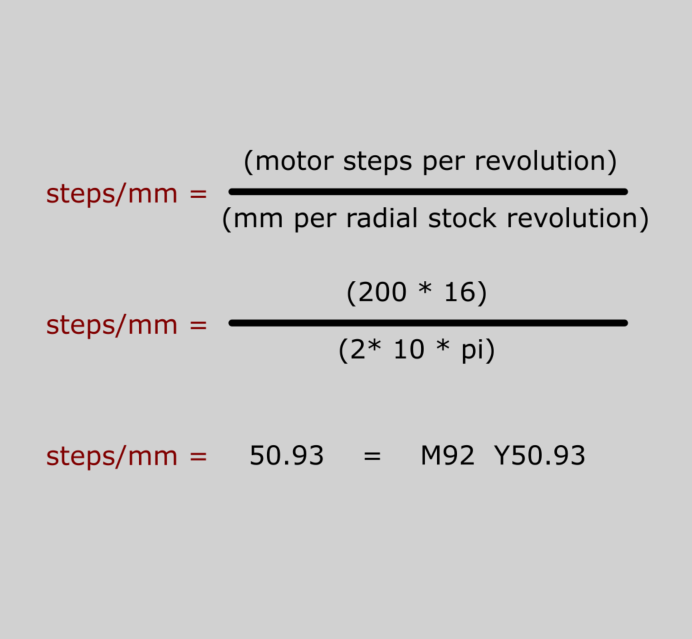
We are very nearly done but we still have one crucial step to make it work. We need a command to change how much the rotary (y) axis moves with each step. This is important for mapping linear movement on to round stock. If you can imagine, when the router is at the top of the stock, at its origin, it needs to know how many steps one revolution is.
In your firmware there is a setting that tells the motors how many steps (microsteps) to move a physical millimeter. We are going to override this in the gcode file.
Most stepper motors are 200 steps per revolution. Most steppers will probably have 16 microsteps enabled per step. If the circumference of 5mm radius stock is 10π then I would do (200*16)/10π. That gets us ~101.86 meaning there are ~101.86 microsteps (steps) for every millimeter traveled. To commit this change to your file just add a M92 command at the beginning of your gcode that looks like this: "M92 Y101.86".
Once you add in this line to the gcode file it never hurts to check that this is indeed correct for your setup. You can run a gcode file with just a straight line along the rotary (y) axis that should be the circumference of the stock and make sure that it makes exactly one rotation.
This is all pretty confusing so don't worry if it doesn't make sense, but, this does work.
After that it's a walk in the park! Just add this line into any of the flattened mesh gcode files that you would like to print. Attach your stock, set the home at the stock height above the center of the motor, cut, and beep-bop-boop you're all done, you have an actual part.
Thanks for Reading!
Congratulations! I hope this could help you out in some way either for specific details or for inspiration for any number of things! If you enjoyed you can support me morally by cheering me on in the comments or by donating to help offset the very expensive $12 cost of this project $$$. Thanks for reading!