Carnivorous Plant
This instructable was created in fulfillment of the project requirement of the Makecourse at the University of South Florida (www.makecourse.com)
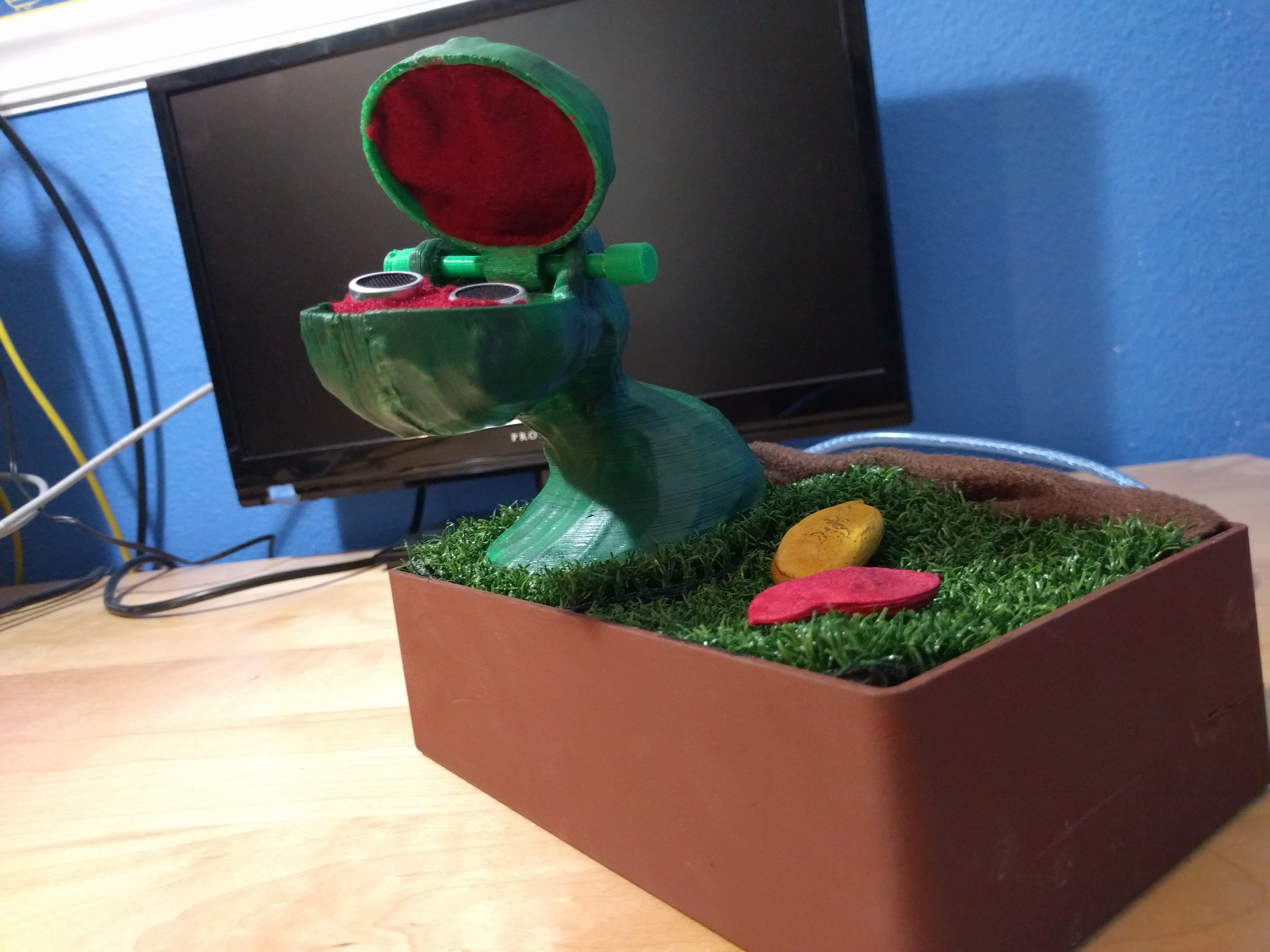
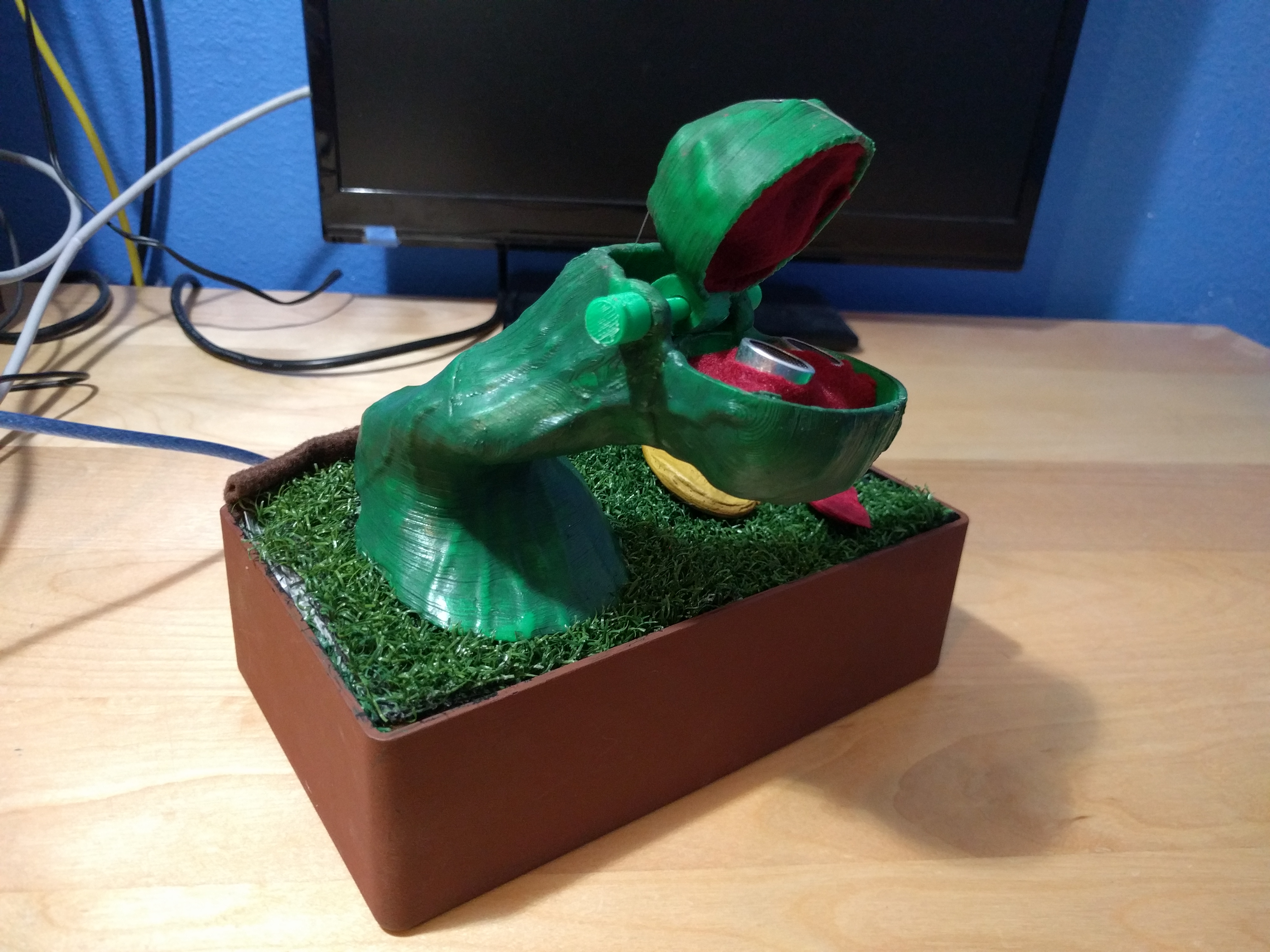
This Instructable will show how to make a carnivorous style plant out of 3D printed parts and electronics.
Gather Materials
3D Printer Materials:
- A 3D printer or access to one
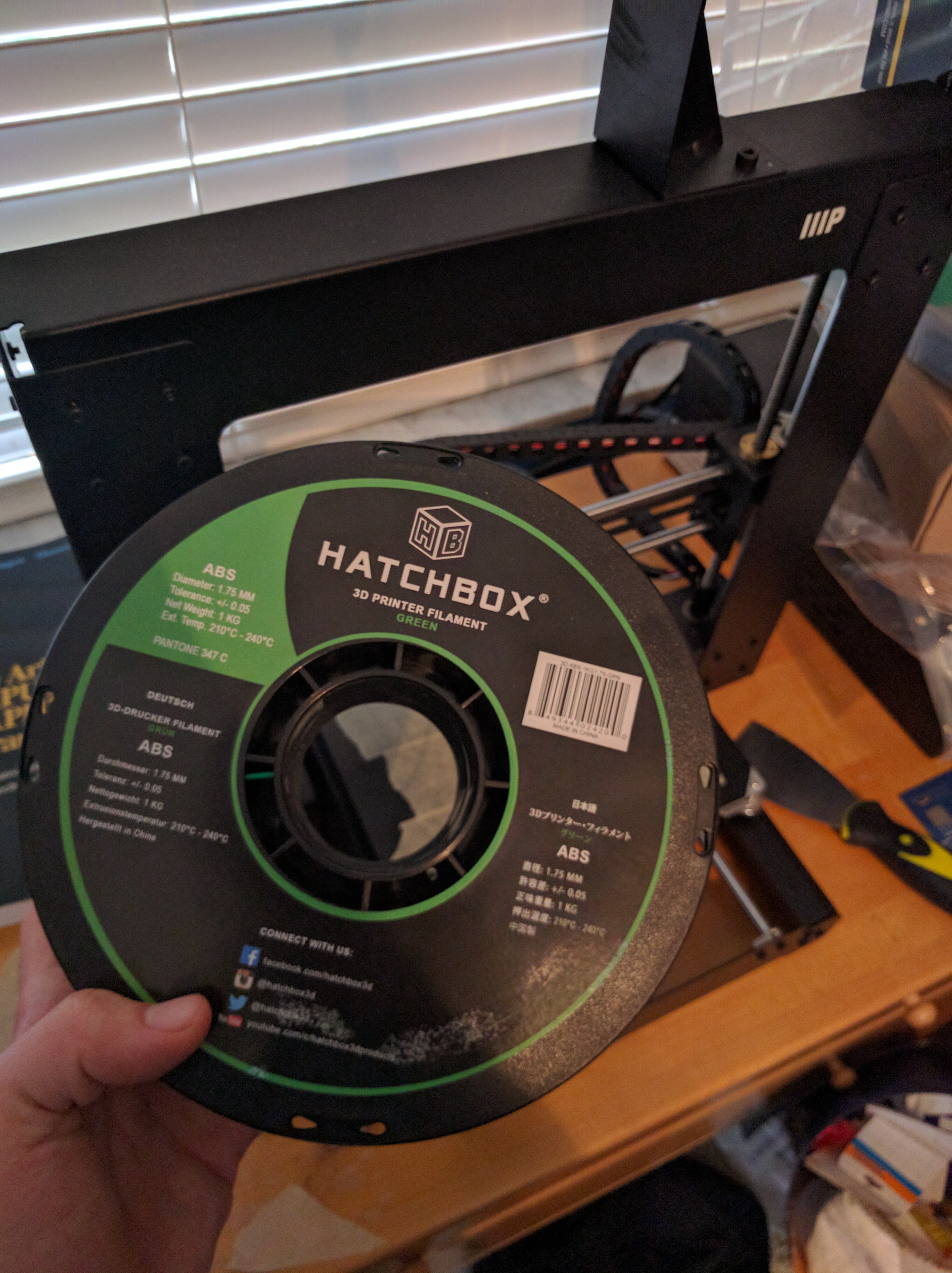
- Hatchbox Green ABS Filament
Electronics:
- Arduino Uno Rev3
- Breadboard and 10 pin male/female connectors
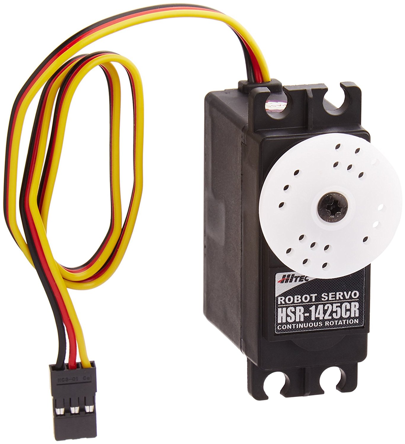
- Hitec 31425CR HS-1425CR Continuous Rotation Dual Ball Bearings Servo
Hardware
- Fishing Line
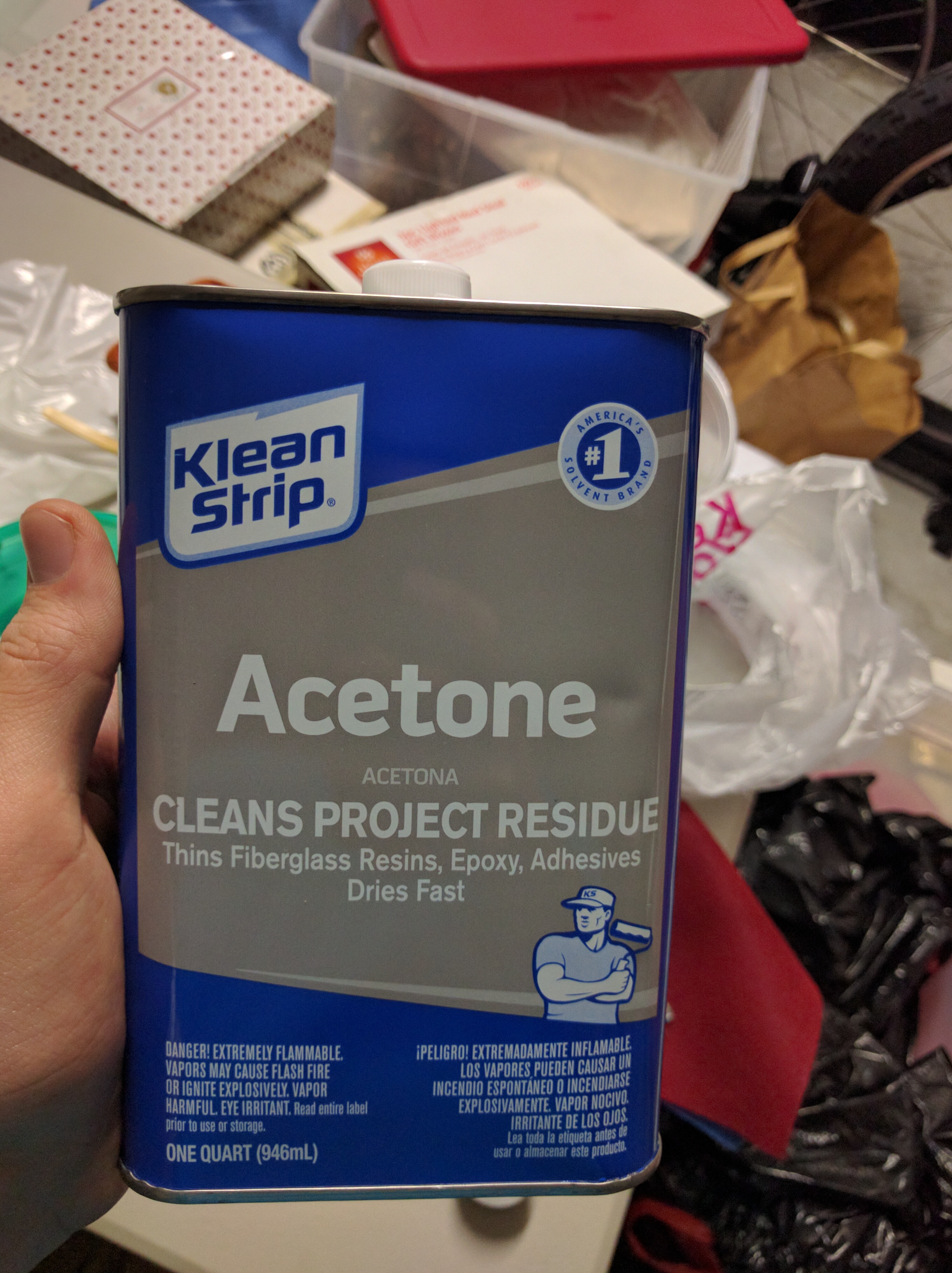
- Acetone
- Loctite Plastic Adhesive
- Sandpaper (high grit, 600+)
- Acrylic paints and brushes/sponges
- DC-47P DC Series Heavy Duty Electronics Enclosures
- Artificial Grass (free swatches at local hardware store's flooring dept)
- Duct Tape
- 1x 1/2 inch PVC cap
- Short section of 1/2 inch PVC pipe
Print All 3D Printable Parts
The plant is broken into four main parts, plus a peg and some stoppers. It will be assembled with the Plant Base on the bottom, the two Bottom Jaw + Top Stem halves glued together and then glued to the Plant Base, the peg will go through the hole at the top, and the Top Jaw will be raised by the peg. The stoppers will keep the peg from sliding out.
The parts in this Instructable were printed using a Monoprice Maker Select (rebranded Wanhao Duplicator I3). I printed mine with Hatchbox Green ABS 1.75mm thickness, but the exact material isn't incredibly important as long as it prints right. This Instructable uses acetone to help bond the parts which is not something you can do with PLA, so keep this in mind if you decide to deviate because you will need other glues.
I sliced the .stl files in Cura, but in whichever slicer you use, you must use a 1.1x scaling multiplier minimum. This is an unfortunate artifact of realizing that the housing of the bottom jaw was just slightly too small for the proximity sensor, but as long as this multiplier is used everything should print smoothly.
Make sure to print the Top Jaw and the two Bottom Jaw + Top Stem files with the flat sides down, this will allow for a much easier cleanup process.
Assemble 3D Parts
First, check that everything fits correctly. Make sure the proximity sensor fits nicely inside the bottom jaw, that the peg fits through everything right, that the three big parts line up right. If the proximity sensor does not fit in correctly, reprint at a slightly larger scaling and try again (it's best to print the two bottom jaw parts first in case of this scenario).
Clean up any rough parts with sand paper, and then glue the three large stem pieces together. If everything printed perfectly flat, you should just be able to use acetone which will melt down the ABS plastic allowing you to bond the parts easily. However, if any parts did not print perfectly flat (lifted up during the printing process like my parts), you will need to roughly glue them together. It will look awful at first, but you will be able to fill in the gaps by melting down your support parts in acetone and using that molten plastic mixture to fill in the cracks. After sanding and painting, this will be barely noticeable.
Let the glue dry as you work on your enclosure.
Assemble Enclosure
Unscrew the lid of the enclosure, and set aside.
Decide which side of the box you will have the plant be above, and which side it will not. The side it will be above will have the servo, and the side it will not will have the Arduino. Place the Arduino on that side, and decide which direction you want the power cord facing out of. Mark that spot on the box, remove all electronics, and drill out a hole on that spot. If you want, test the drill on the lid of the enclosure first since we will not be using that. Clean up the hole and make sure the power cord fits through.
The carnivorous plant is going to utilize a servo and a fishing line to wind up and drop the top jaw of the plant. Therefore, we need to create a "spool" of sorts protruding from the servo so it can wind in this manner. Take your fishing line and wrap it tightly with duct tape along the PVC pipe, then bring the tape over an open flame to melt the fishing line inside of the tape. This will ensure the fishing line is bound to the spool stronger than the servo is capable of pulling.
Attach the cap to the pipe, and glue the other end of the pipe to the face of the servo. Glue the servo to the corner of the enclosure you plan to place the plant on, and let everything dry. Tie the other end of the fishing line length to a paper clip or some other small object, this will make it easier to snake up the center of the plant later on.
You now have a servo in one corner of the box, and the Arduino in the other. In the end there will be a small breadboard laying on top of the Arduino, so the rest of the space in the box is unused. Take several small sections of PVC pipe and glue them in the unused areas to be used as supports.
As everything dries, assemble your electronics.
Assemble Electronics
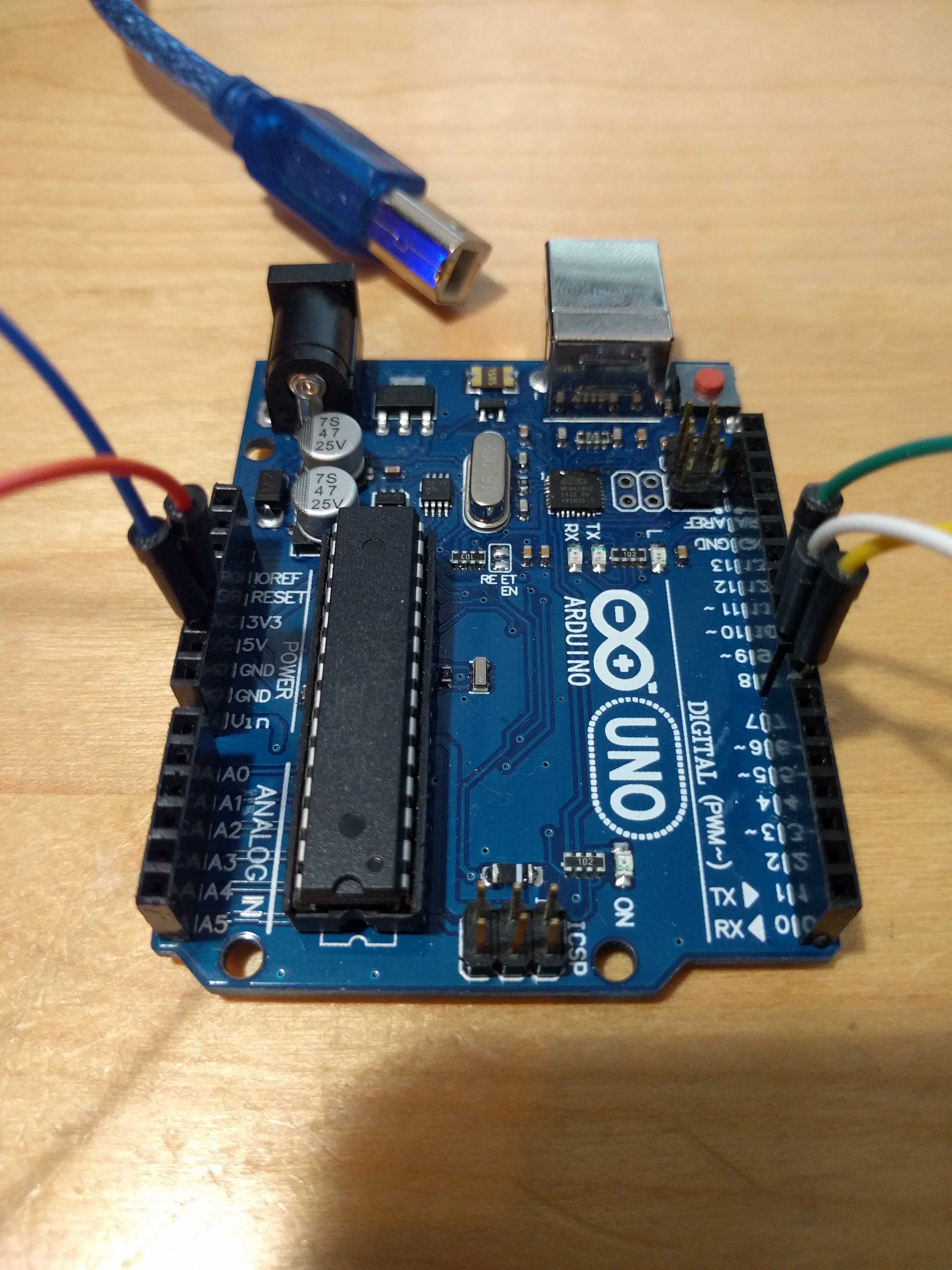
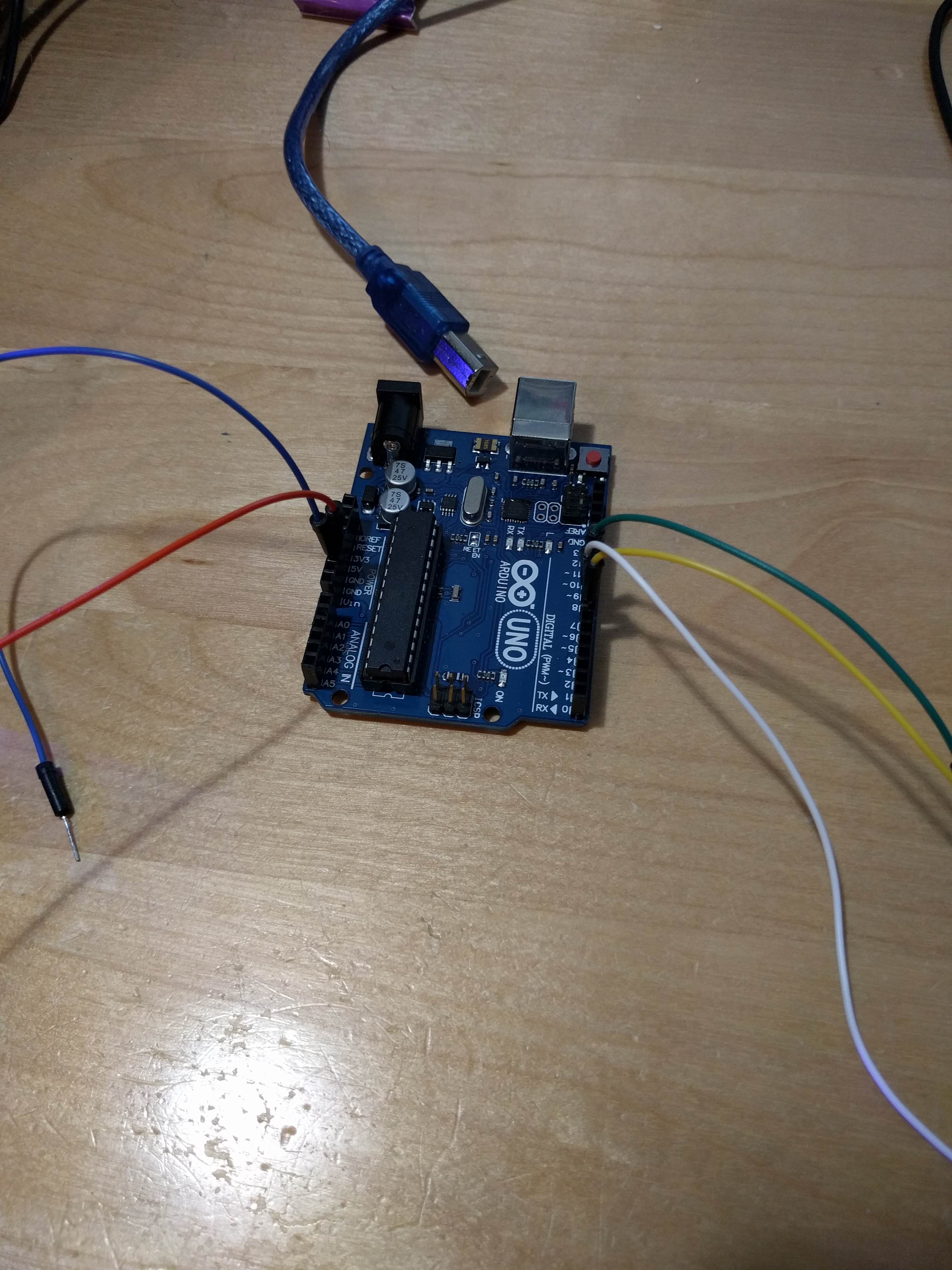
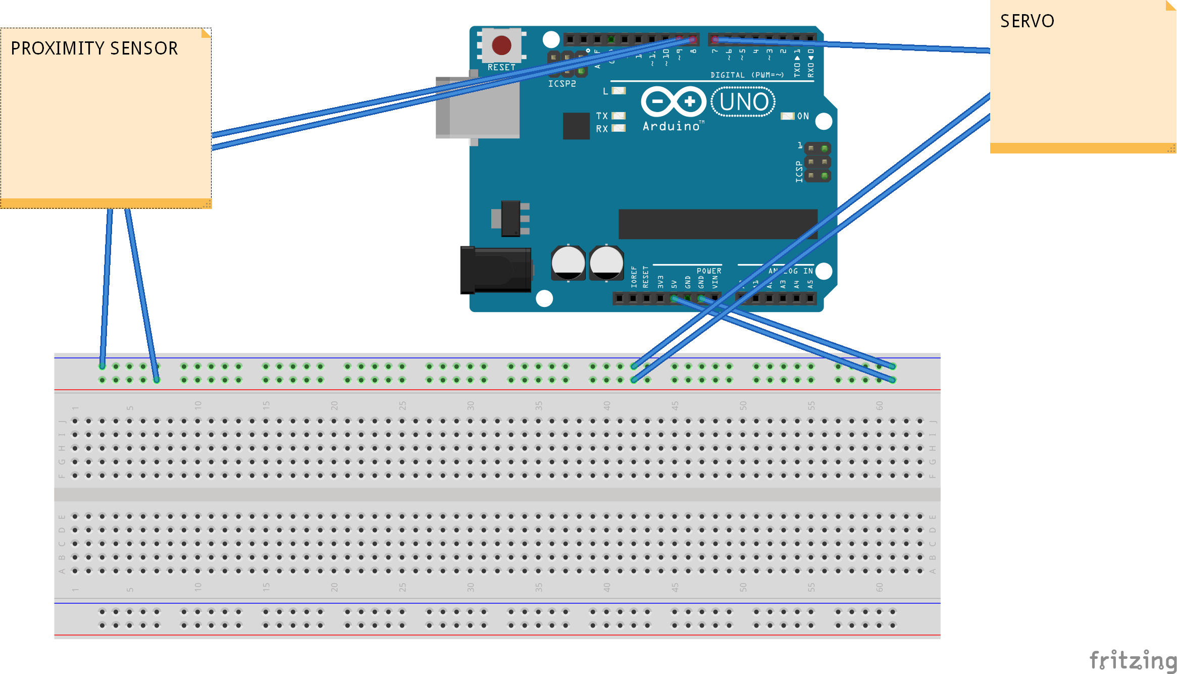
The proximity sensor has an output of four male pins (Power, Ground, Echo, Trigger), and the servo has an output of three female pins (Power, Ground, Control). In total we have seven pins we need to worry about, two are power, two are ground, three are specialty.
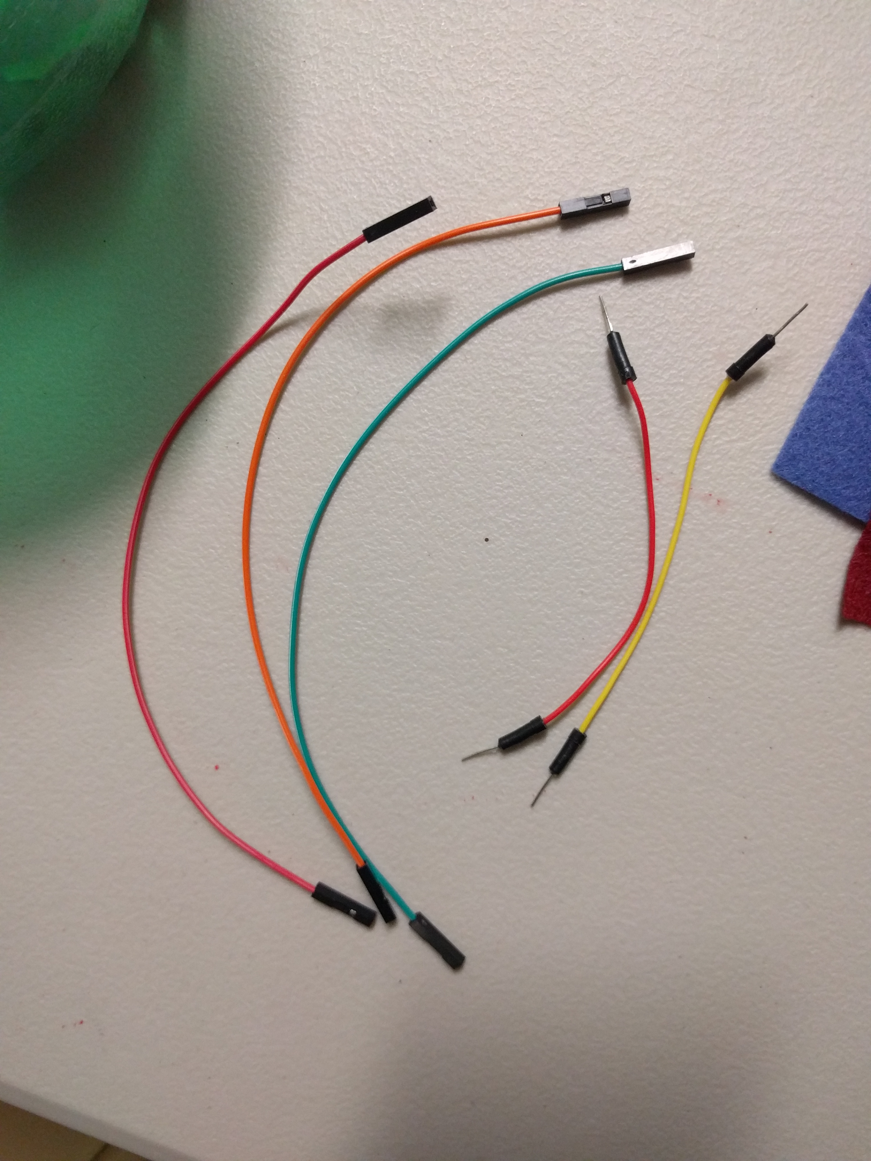
Take three male pins, and place them in digital pins 7, 8, and 9 on the Arduino. Pin 7 will be connecting to the control pin of the servo, this tells the servo how to move. Pins 8 and 9 will connect to the Echo and Trigger pins on the proximity sensor, this tells the Arduino how far away incoming objects are. Attach two female pins to the Echo and Trigger pins coming out of 8 and 9, and you are done. The male pin coming out of 7 will now go directly into the servo, and the male + female pins coming out of 8 and 9 will now go directly into the proximity sensor.
Take your breadboard and place three red male pins into the power line (red strip on either side). Two of these will connect to the servo and proximity sensor, and the third will go directly into the Arduino's 5V pin. Pick the one you want going to the proximity sensor, and attach a female pin into it.
Do exactly the same with the ground wires, take three blue male pins and place them into the breadboard's ground line, two will go to the servo and proximity sensor, and the third will go to the GND (ground) pin on the Arduino (any of them will do). Pick the one you want going to the proximity sensor, and attach a female pin to it.
Your Pin 7, Power, and Ground pins for the servo can be immediately plugged in. Gather the four female pins for the proximity sensor and temporarily plug them into the sensor so we can test the code and make sure everything is plugged in correctly.
Compile Code and Test
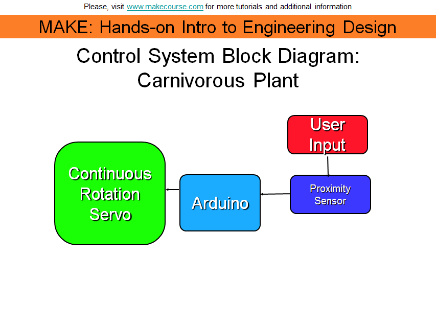
Plug the Arduino's cord into a computer, place the HCSR04 files into your Arduino's library folder, and compile the attached code "deliverable" onto it.
The HCSR04.cpp file has three functions: A constructor (creates the object), a readSensor() function, and a getLastValue() function. The constructor receives two values for which pins you are using as Echo and Trigger, and creates a proximity sensor object for the Arduino around that.
The readSensor() function converts the data received from the proximity sensor into a centimeter value that the user can use in calculations.
The getLastValue() function sends back how far away something was from the proximity sensor the last time it was calculated (this is not used in this sketch).
In the deliverable.ino file, we include this proximity sensor library along with a build in library for the servo. We define which pins we're using for the servo and proximity sensor, and create the servo/proximity objects. The setup() function starts a Serial line that can be used for debugging.
In the loop() function, we constantly check to see if something is within 5 centimeters of the proximity sensor. If it is, the IF statement begins, and power is connected to the servo. Now with this particular brand of servo, when the attach() function of the servo library is used, it tells the servo to start moving immediately, and it will not stop moving until it's detached. This does differ from other servos. So in this case, the amount we want to move must be controlled using delay() functions, we tell it how long we want it to move instead of how far. So we tell it to move for half a second, detach power, delay of two seconds of it staying closed, then reconnect power and wind it back up the opposite direction for half a second. Then we detach power again and give it a five second delay so it doesn't immediately chomp down on whatever it just let go of, and the loop restarts.
Now, once the code compiles, we must make sure it's working properly. We are looking for two things here.
First, we want to make sure everything responds correctly. When an object (your hand, a piece of paper) goes over the sensor within 5 cm, the Serial Monitor on the computer should record it as such, and the servo should move. If this is not happening, double check all of the wiring, make sure everything is grounded, make sure you did not accidentally attach the powerline to any of the specialty pins, and try turning it off and on again.
Once everything is responding correctly, we want to take note of which direction the servo is turning. Give the fishing line an extra wrap around the spool in the direction you taped it, and see if the moving servo is pulling it in more or pushing it out. Our end goal for the plant is that when the proximity sensor activates, the servo will spin to release fishing line so that the top jaw will drop under its own weight. Check to make sure that when the servo first moves, it's giving the fishing line slack. If it is not, then in the coding of the Arduino program, for the two myservo.write( ) commands, replace the 1 with a 180 and the 180 with a 1 on lines 29 and 34. This will change the direction the servo turns, allowing it to work properly.
Once everything is working right, unplug the Arduino, unplug the proximity sensor (because we need to connect it at the top of the plant), and proceed to the next step after all the glue has dried.
Decoration
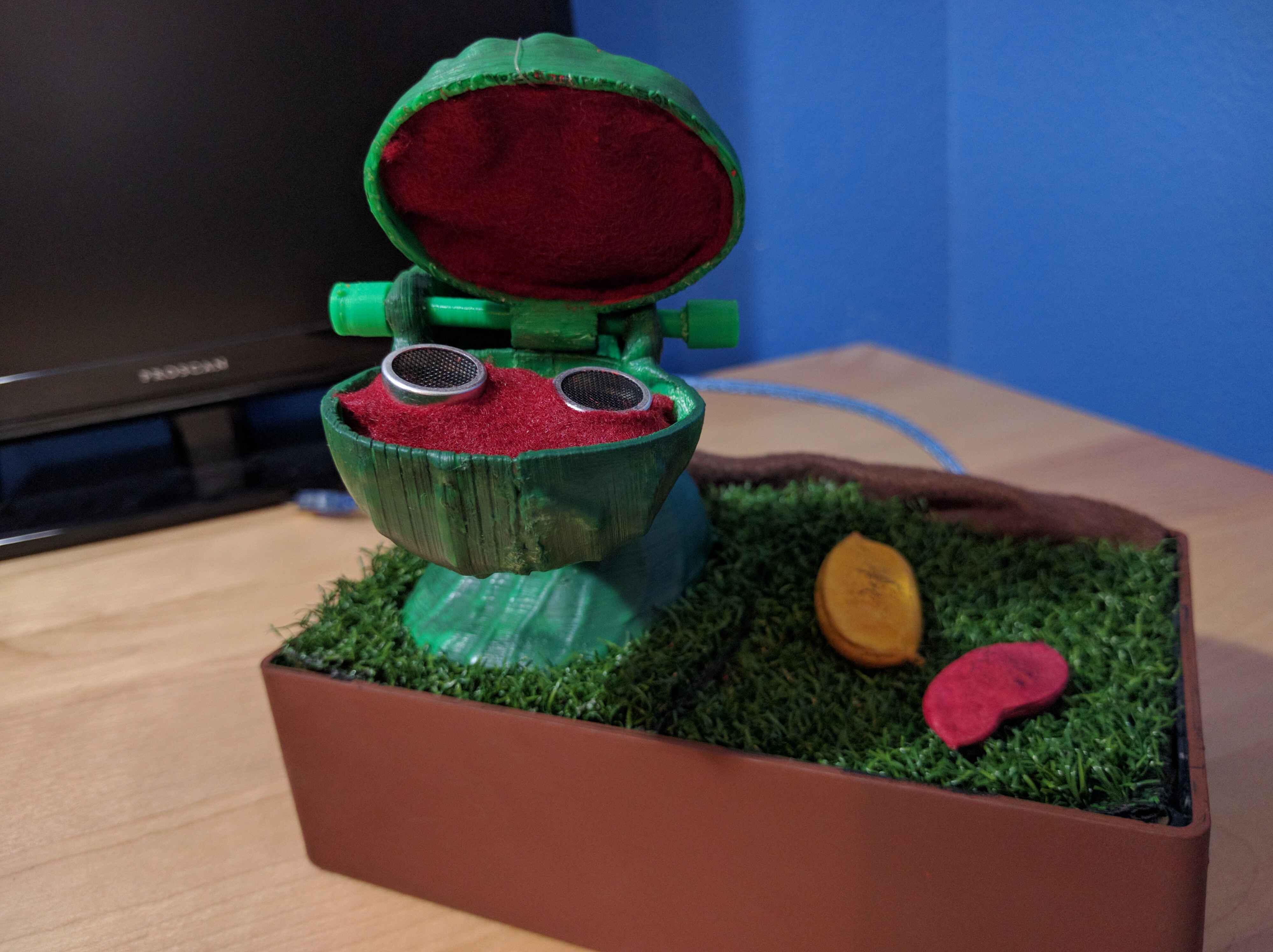
Here is where you can be creative with what you do with my project. These are the steps I took with mine:
I painted the box several times over with a mixture of 3:1 brown to red acrylic paint until the black plastic no longer showed on the box, this gave it a clay pot feel. I suppose you could use an actual clay pot for this instead, but the class I designed this in required us to use the enclosure as a constraint so that's what I did.
Once the printed parts were glued together, I painted them over with a very light coating of acetone. Acetone will melt ABS plastic, so I only left it on for a few seconds before dabbing it off. This gave it a nice shiny look to it. I was extra liberal with it on the seams of where everything glued together, and allowing it to melt more on those areas masked the fact that this multiple parts glued into one.
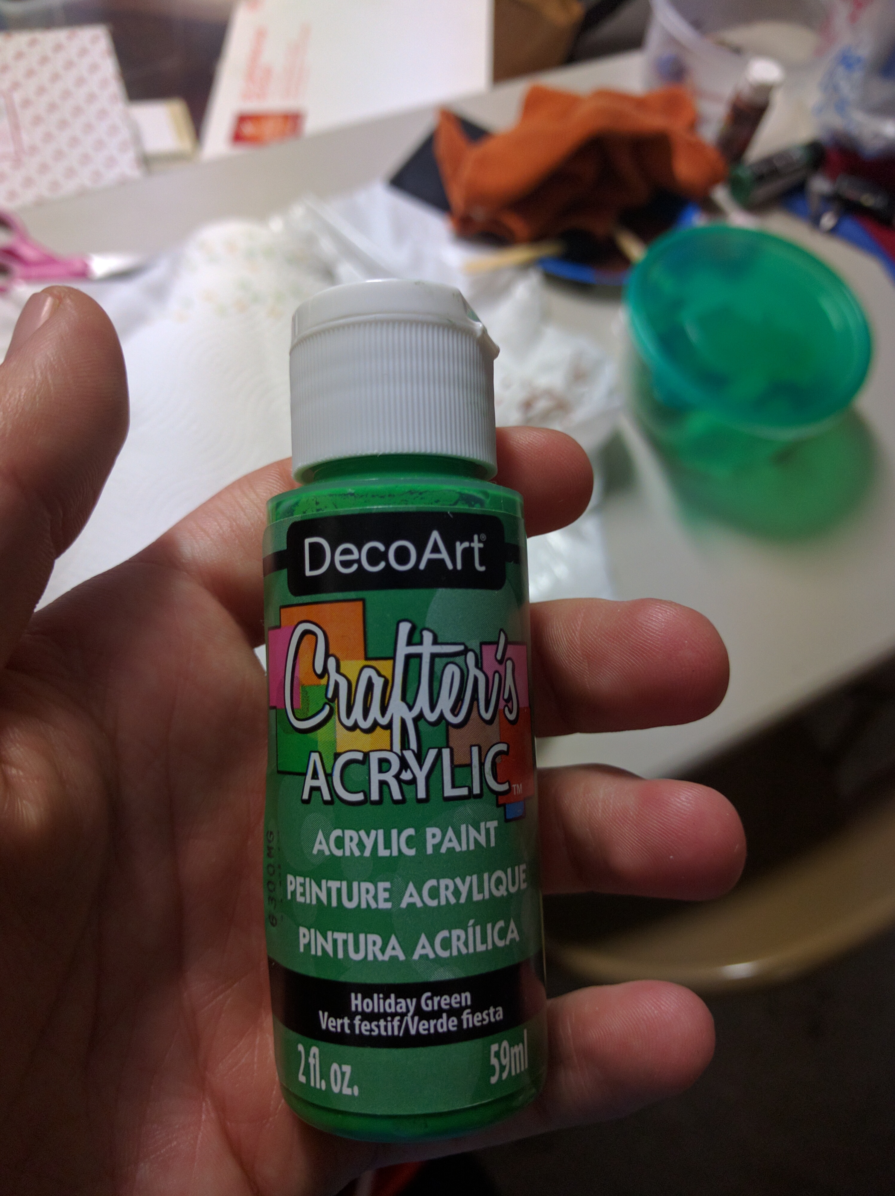
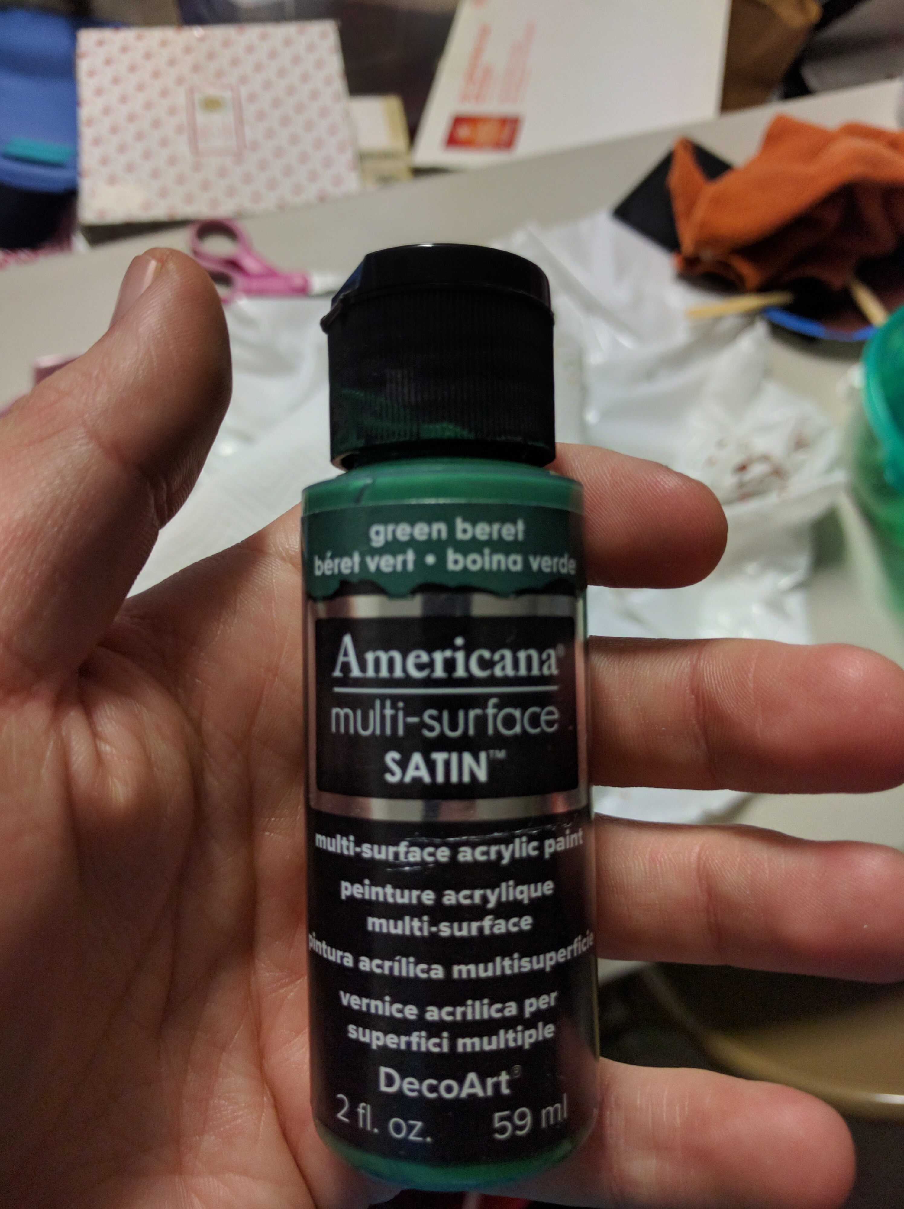
After the acetone was all dried off, I painted my bright green parts with a VERY dark green (something like 5:1 black to green) with just a single layer, giving it black streaks all over the part. I then coated it several times with the shade of green I actually wanted for it, and this blended the black streaks and the greens nicely for a multidimensional color scheme. I then again lightly and quickly dabbed the entire thing in acetone and immediately removed it again, and this let some of the plastic's original bright green to come through while leaving the colors I'd added and giving it a shiny appearance.
I took two samples of artificial grass from the Flooring section of my local hardware store, and cut a hole in the bottom of one to match the hole in the bottom of the carnivorous plant stem. I then "trimmed" the grass in the same shape of the stem, so that the plant could nestle into that bare portion rather seamlessly. In the final assembly, you will glue the plant to this trimmed part, so get it as close to the bottom as you can. Tape and cut the grass sections until it fits the box nicely.
Additionally, I found in the clearance section of Joann's some fake leaves and glued them onto the other end of the grass so it wasn't so barren there. Any kind of natural looking potpourri would do.
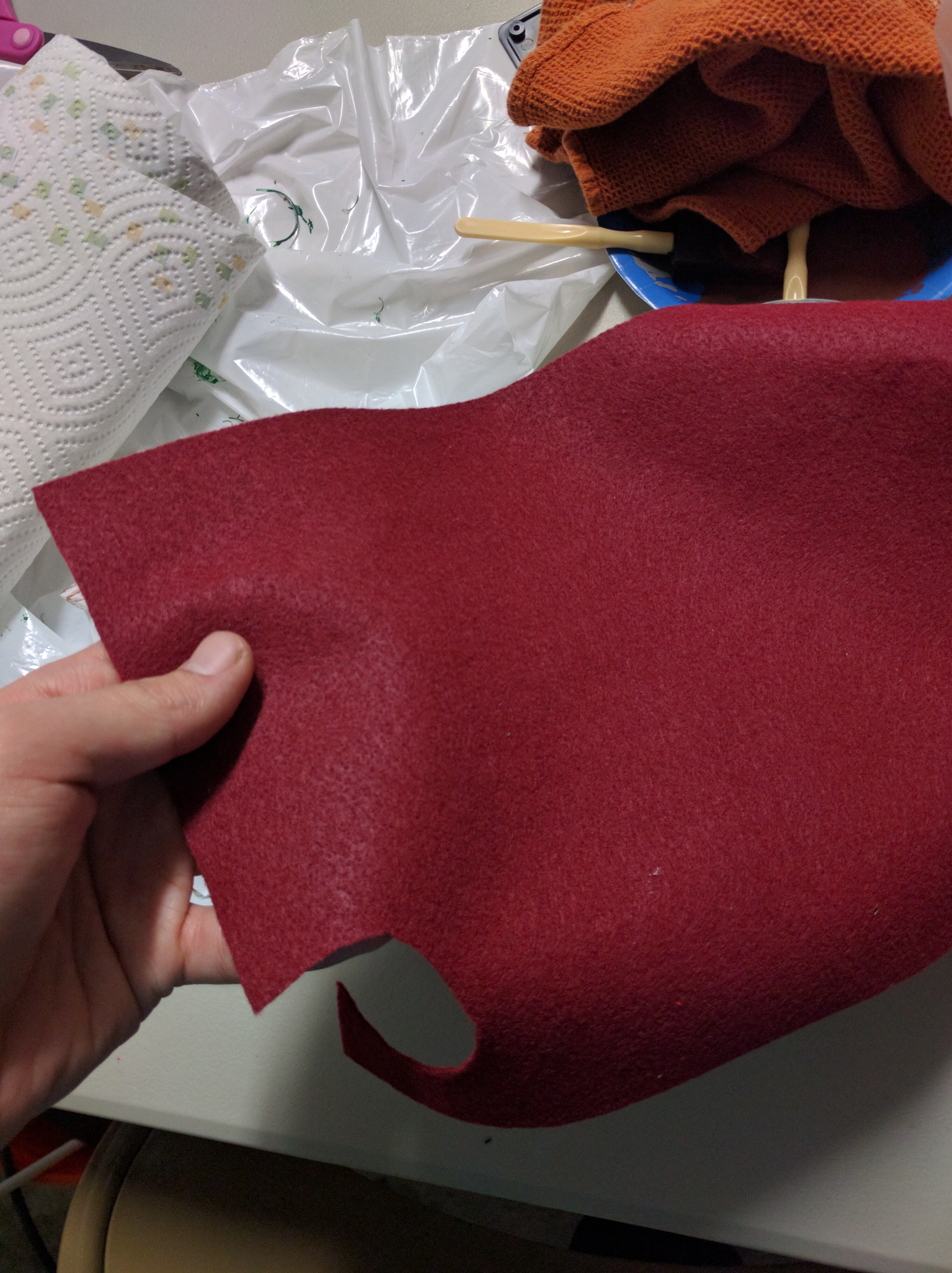
Cut some small sections of dark red felt fabric to fit the bottom and top jaws, this will give it a "tongue" or "mouth" appearance. You will later cut two small holes in the one for the bottom jaw for the proximity sensor's two bits to fit through, worry about this later.
Final Assembly of Parts
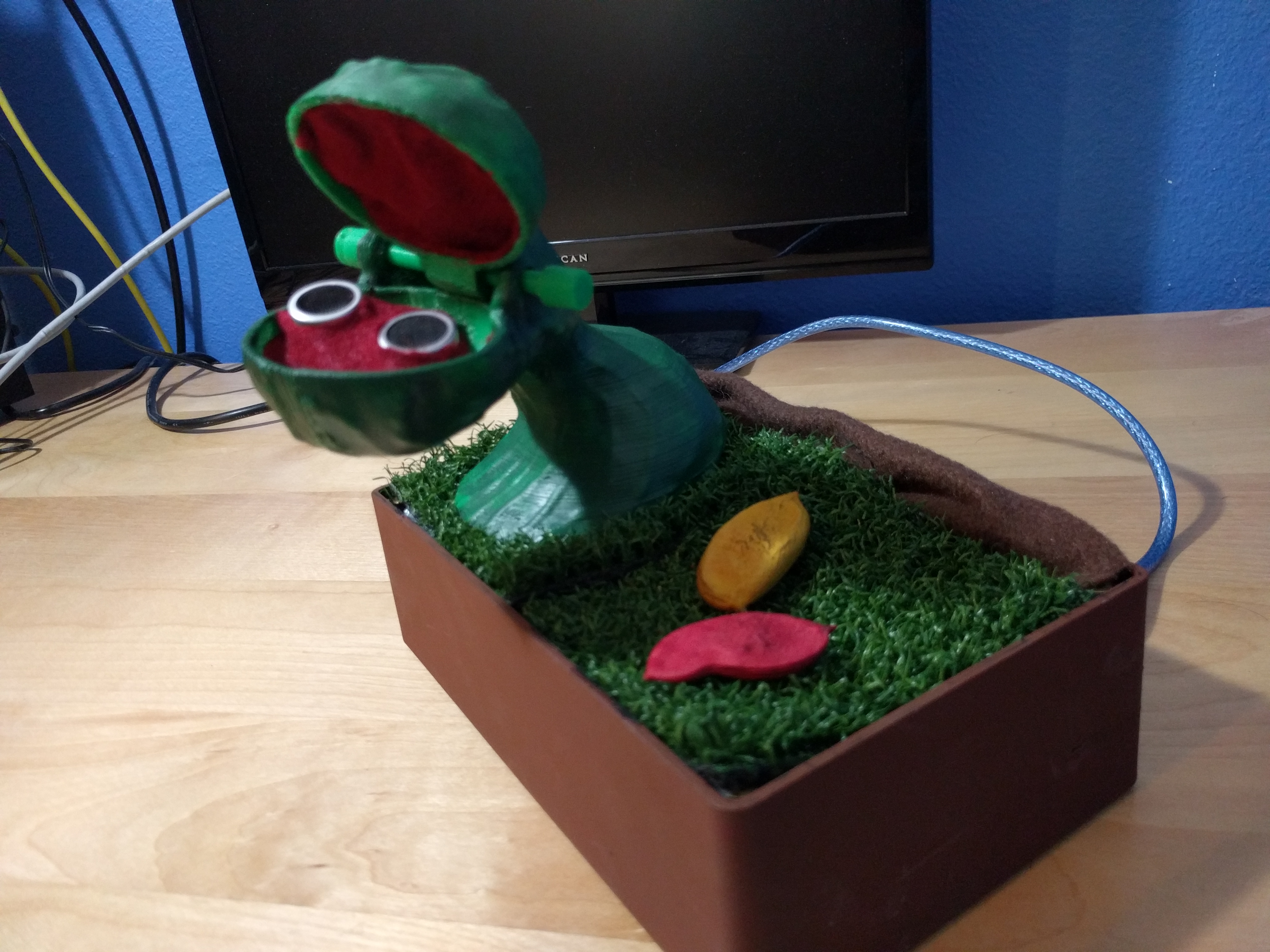
Once all decoration is finished, glue the plant base onto the grass and let dry. Snake the fishing line and proximity sensor wires up the plant. Plug in all proximity sensor wires, and plug in the Arduino and confirm they work properly. Make sure all electronic components are working fine at this point because opening up the enclosure after this point is messy.
Make sure your fishing line is affixed to something (paper clip, large object) so it does not get yanked back down into the enclosure. If you lose your fishing line past this point, it is incredibly difficult to get it back in.
Put glue on all PVC supports inside enclosure, and place grass top onto the supports. To any corners that protrude or stick out, attach strips of duct tape the bottom side and press firmly until the grass nearly seamlessly fits into the box. In my case, the grass swatches weren't long enough and I had a long strip of open area along the box, I placed some brown felt in here with duct tape for a "dirt" effect.
Once everything is dried and settled, slip the top jaw and peg into place. Depending on how the peg and peg stops printed, you may need to glue the stops in. If you have to glue the peg stops in, only glue one in (on the end that gets pulled in by gravity) so you can remove it if need be while you're calibrating the fishing line. Make sure the top jaw opens and closes smoothly, and that it does so without grating against the bottom jaw as it turns. If it does that, it will be difficult for it to smoothly drop down with gravity, take it out and sand it down until it no longer does that.
Take one of your felt pieces and cut holes in it so it will fit over the proximity sensor like a fingerless glove.
At this point, the plant should be nearly fully assembled. The box should be painted and decorated, your electronics are functional and in the right places, your three glued parts should be combined and decorated, your slip-on parts are all assembled. The only thing left is to calibrate the fishing line, and the plant will be functional.
Calibration of Fishing Line
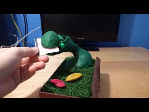
This entire project hinges on the idea that the top jaw will drop down by gravity. For this to work, the fishing line must be calibrated right so that when it pulls up, the jaw will be at an angle just far enough that it would fall without the support of the line, but not so far that it triggers the proximity sensor on its own. This is a tricky balance.
Take your fishing line coming out of the plant and bring it along the top of the jaw. Pull it into the internal cavity, and find a point on the inside you want to affix it to. Adjust the top jaw until you are at that point where you feel it will fall under gravity but not trigger the sensor. Loosely tape it to this point, make sure it stays, and turn on the Arduino. If it activates, you need to bring it up more. If it doesn't, you're fine. Turn it off, and FIRMLY affix it to that point. Duct tape it hard in and melt it to that point, and use tons of glue.
For weight, I used clay, packed it in tightly over the tape, and then placed my final piece of felt on. Turn on the Arduino, make sure it works correctly. The fishing line should not be pulling out of the top jaw, if it is then you did not affix it in strongly