Cardboard Bender
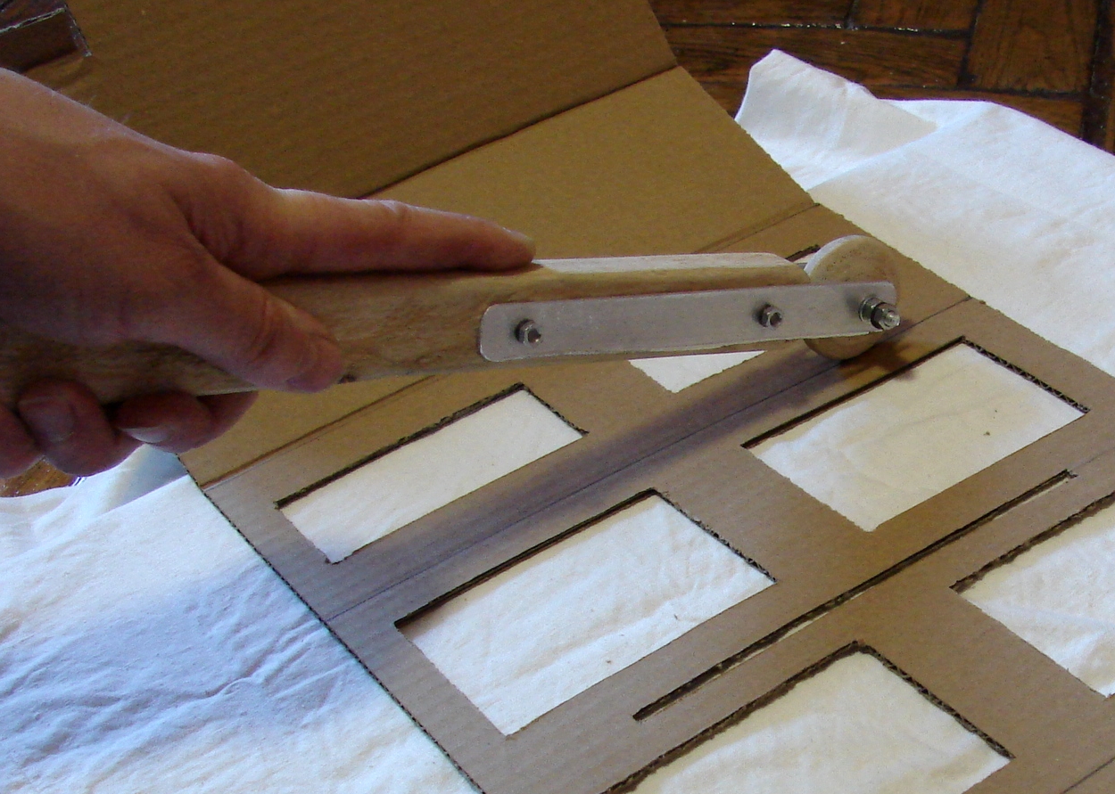
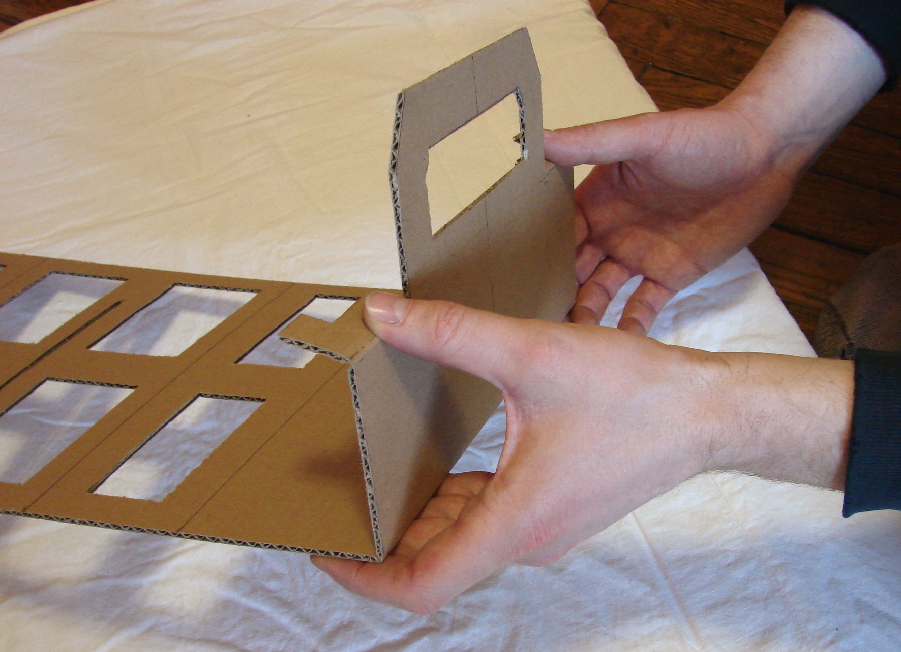
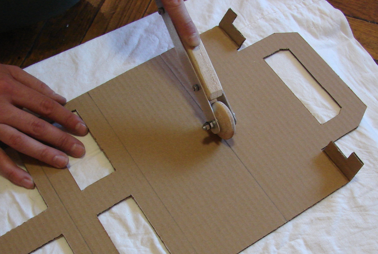
A tool is something that makes life easier and more convenient. I have got a rather huge mass of cardboard (a cause of a new furnishings :-)) and appropriate number of ideas to make something with it (Bag for Containers). One problem is bend operations. Cardboard plates have a multiply layer (as usual) so I get clumsy splits during bending. To prevent such behavior I decided to flatten cardboard according the bend line. At this moment we get situation for a ... NEW TOOL. How to make flattening along the path? Certainly, using a one of the ancient inventions – the Wheel. We need only move the wheel (roller) along the path on cardboard surface with giving insignificant pressure. This principle we use in home preservation to connect bank and cover (or let's remember about the roller-machine for road construction). Concept of a tool is very simple: roller (wheel) and handle – nothing more.
Materials and Tools
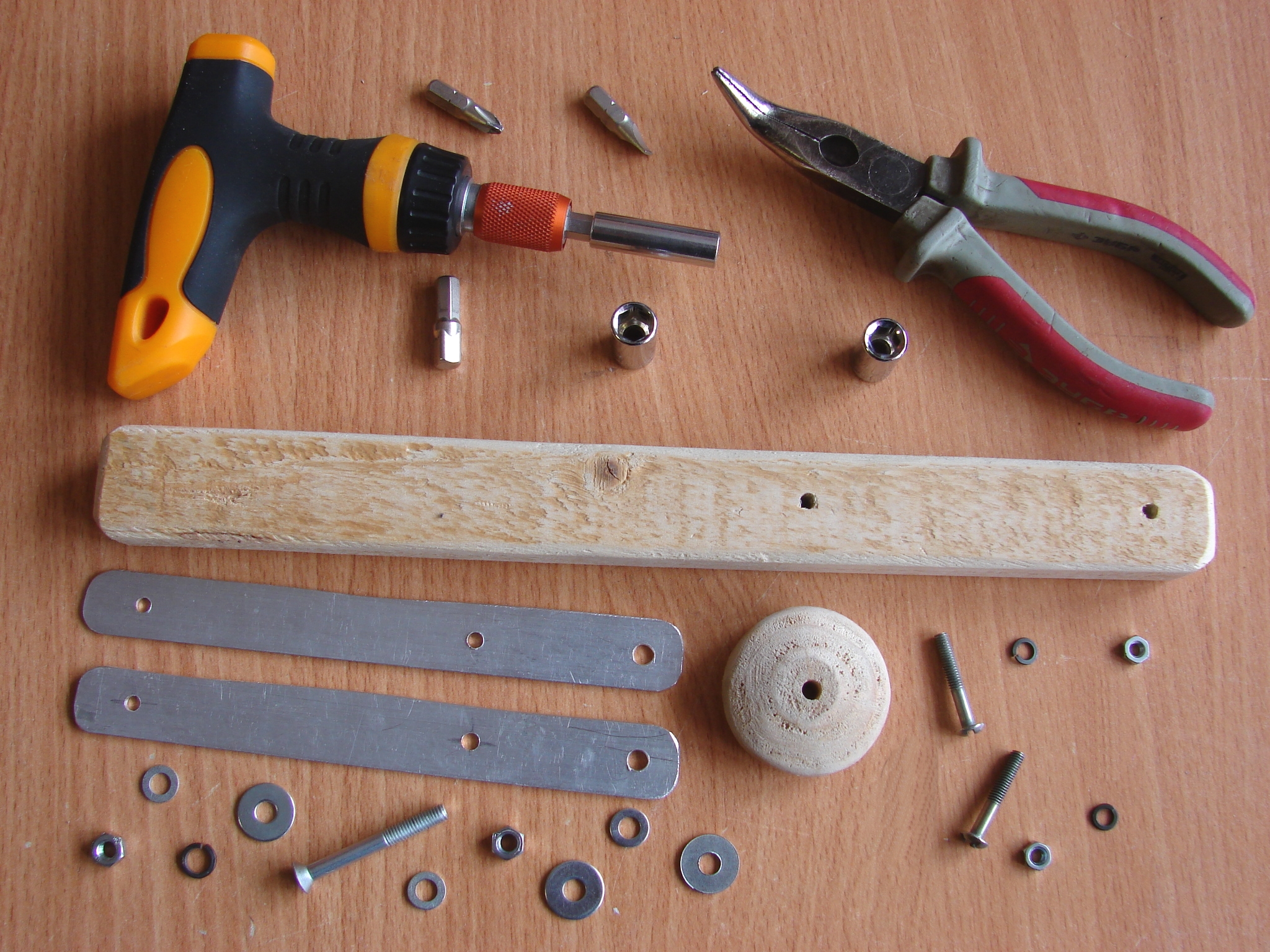
Materials:
- 1 wooden slat (300x30x20 mm) for a Handle;
- 2 aluminum plates (150x20x1 mm) for a Bracket;
- 1 wooden cylinder (D45xH16) for a Roller;
- 1 screw M5x40;
- 2 screws M4x30;
- 1 spring washers M5;
- 2 spring washers M4;
- 3 plane washers M5 (D15);
- 3 plane washers M5 (D10);
- 2 hexagon nuts M5;
- 2 hexagon nuts M4.
Tools:
- screwdriver with a bit set;
- combination pliers;
- drill, hacksaw, rasp, file, sandpaper (to prepare parts).
Parts Preparation
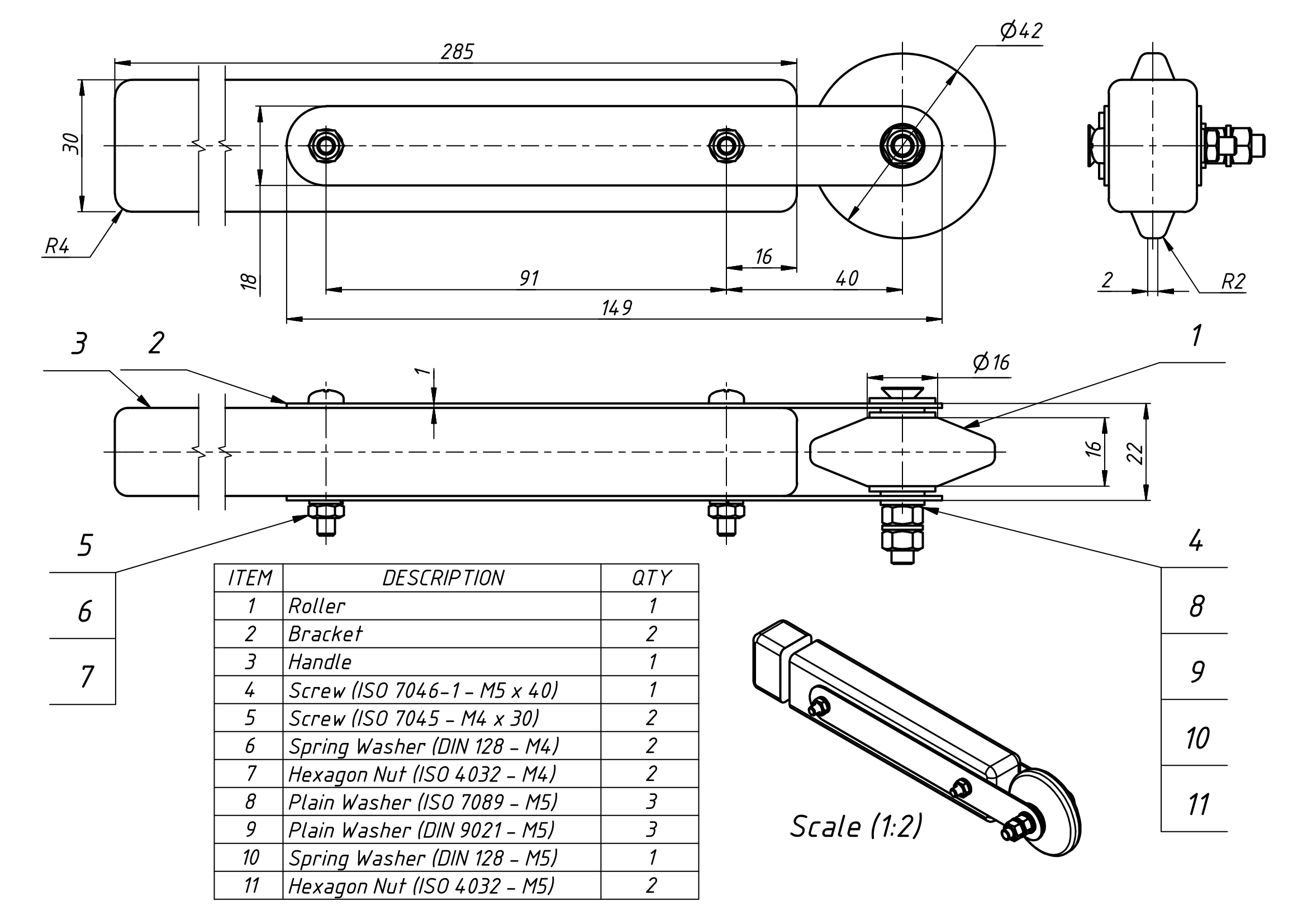
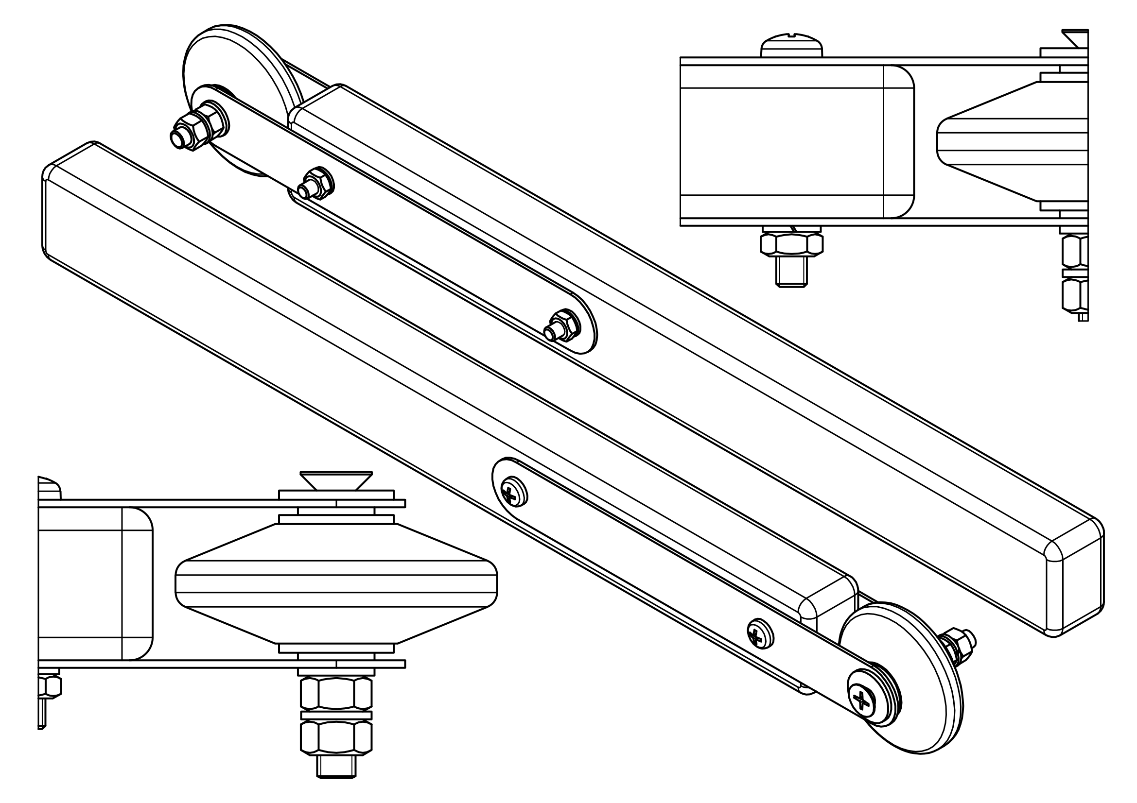
According to design drawing the "hand-made" parts are: the Roller, the Handle and two Brackets (link1 (google drive), link2 (yandex drive)). The main part is a Roller. You can make it from a wooden cylinder using a turning lathe (or hand rasp ;-)). Keep in mind that outside working surface of a Roller need to have appropriate width (no more then 4-5 mm) and shape (rounded edges). For a Brackets you can use appropriate aluminum or steel plates. I made these elements using a piece of standard aluminum angle profile by cutting it along the corner edge. The Handle is any wooden slat with appropriate geometry. What about screws, nuts, washers ... Certainly you can see the parts list in the design drawing and on Step 1. But perhaps you find analogical elements into your "home workshop". So, we have prepared all parts. Let's start assembling.
Downloads
Assembly …
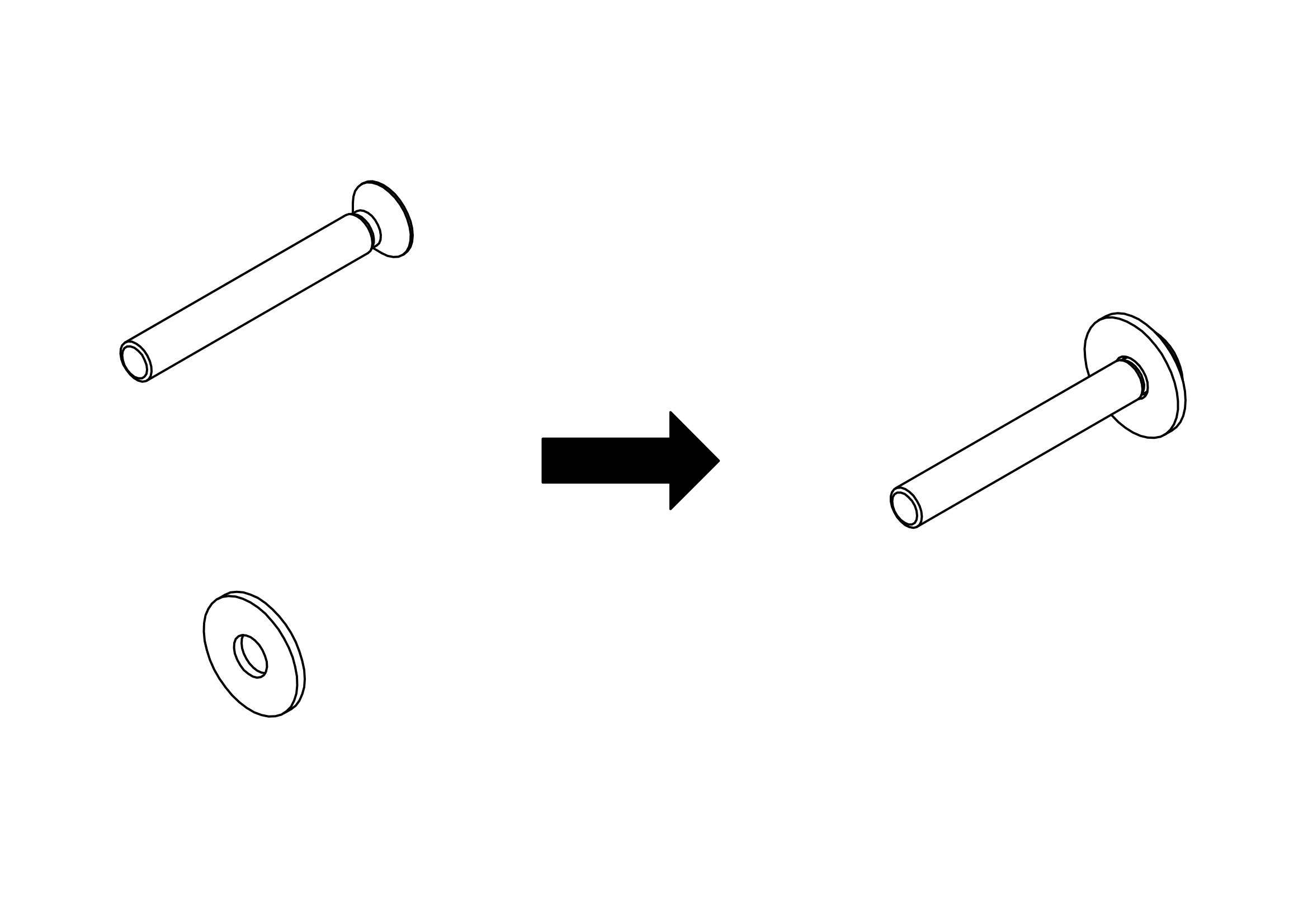
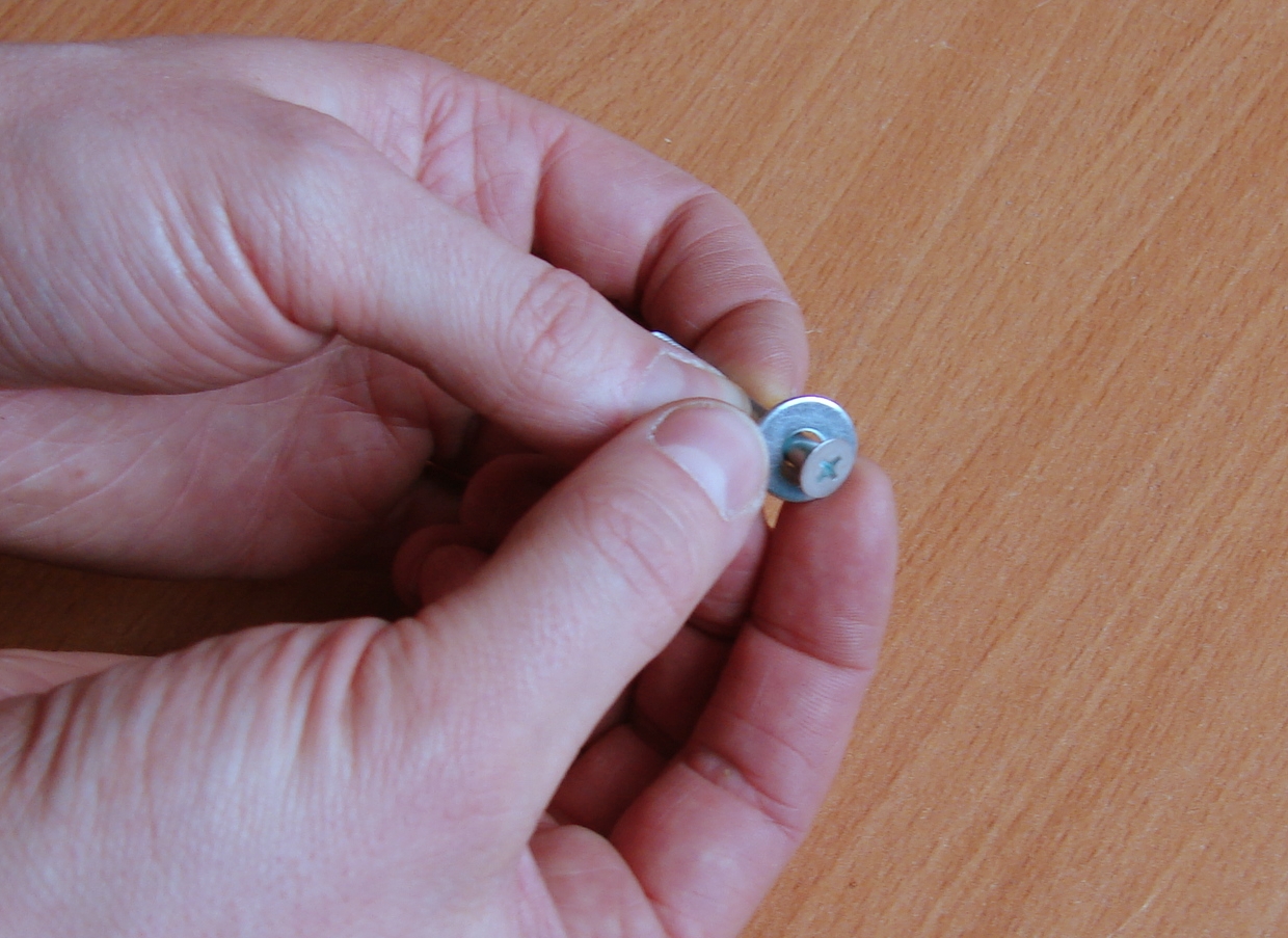
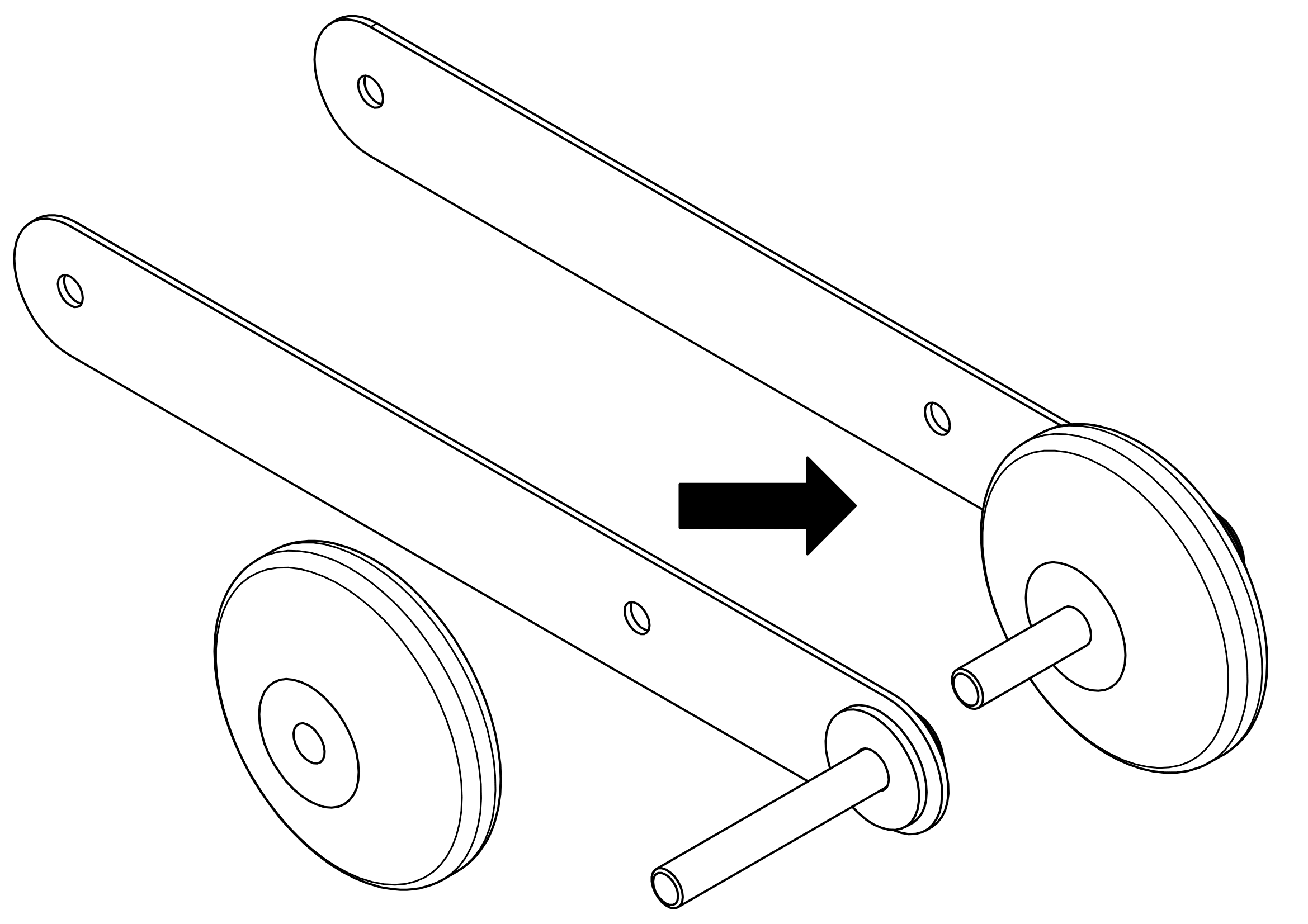
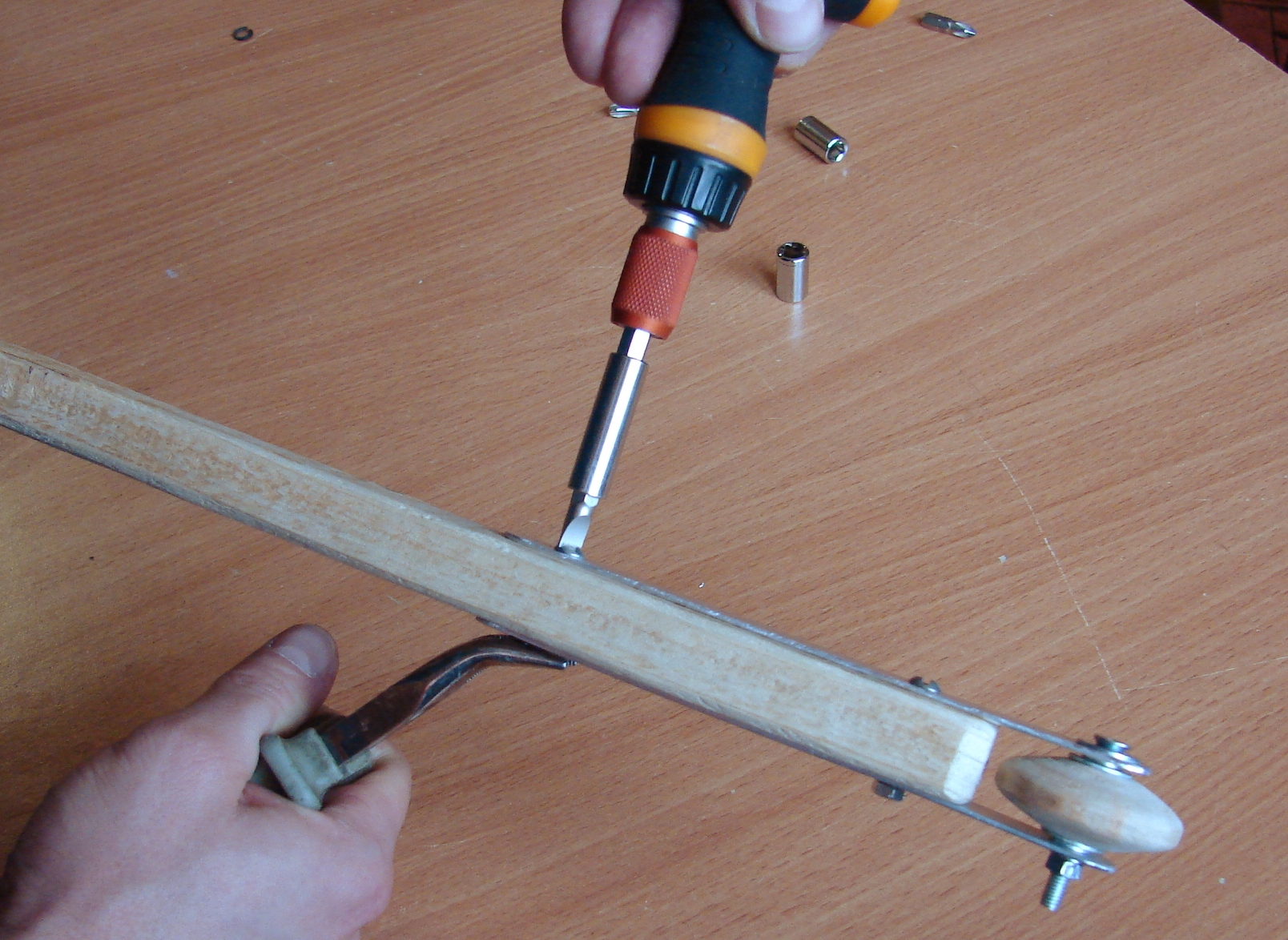
The base of assembly is a Roller axis.
Assembly …
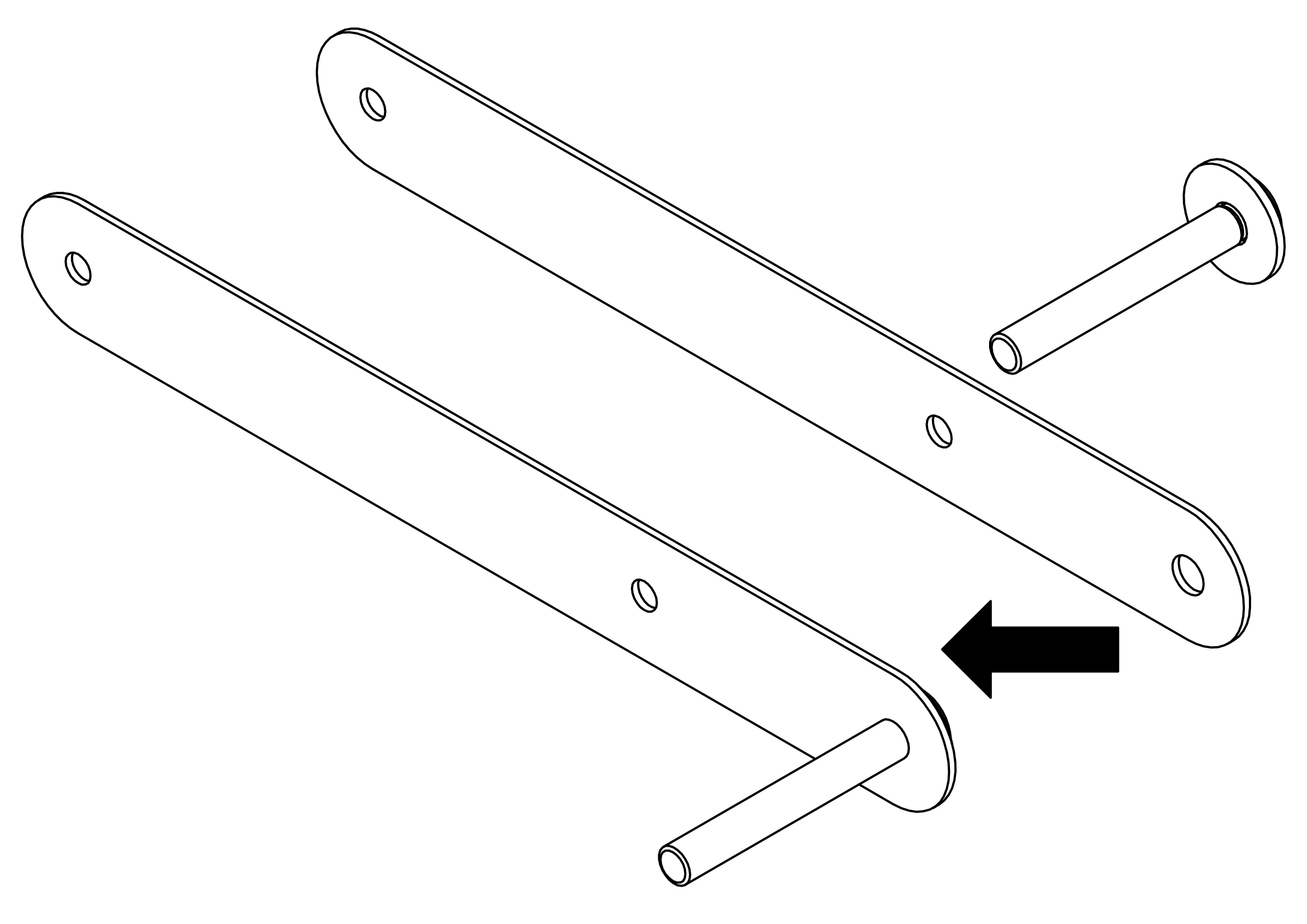
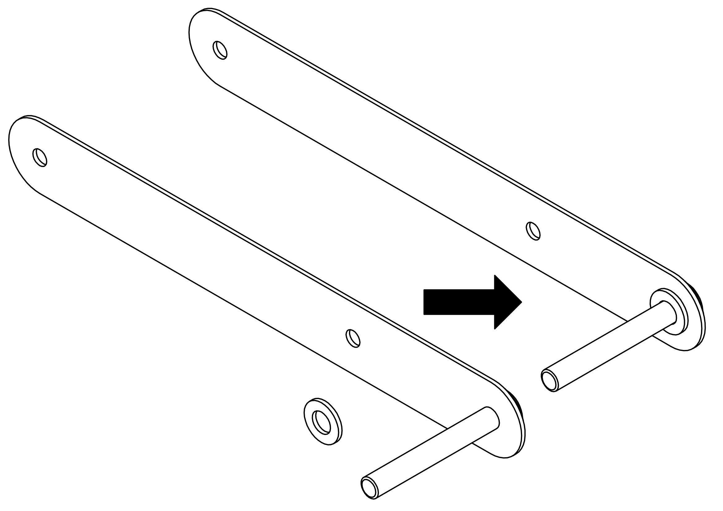
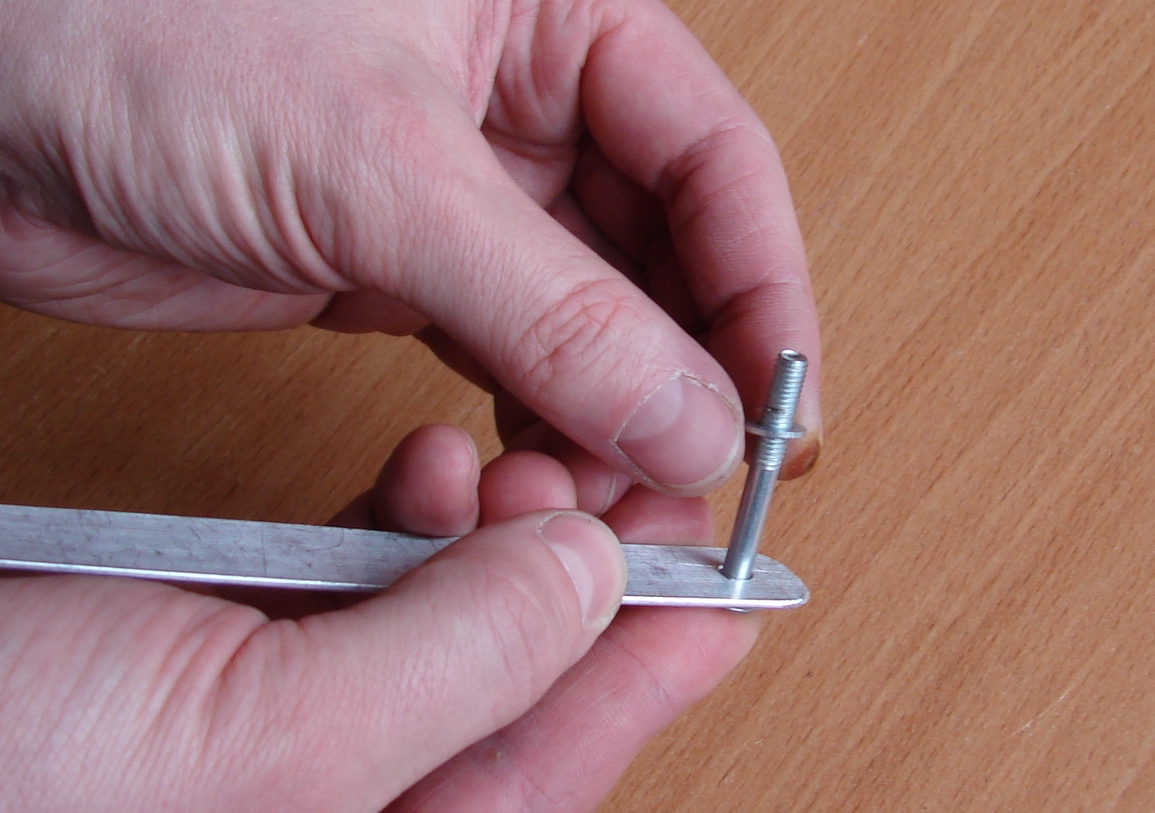
Put the first Bracket on the axis.
Assembly …
Assembly …
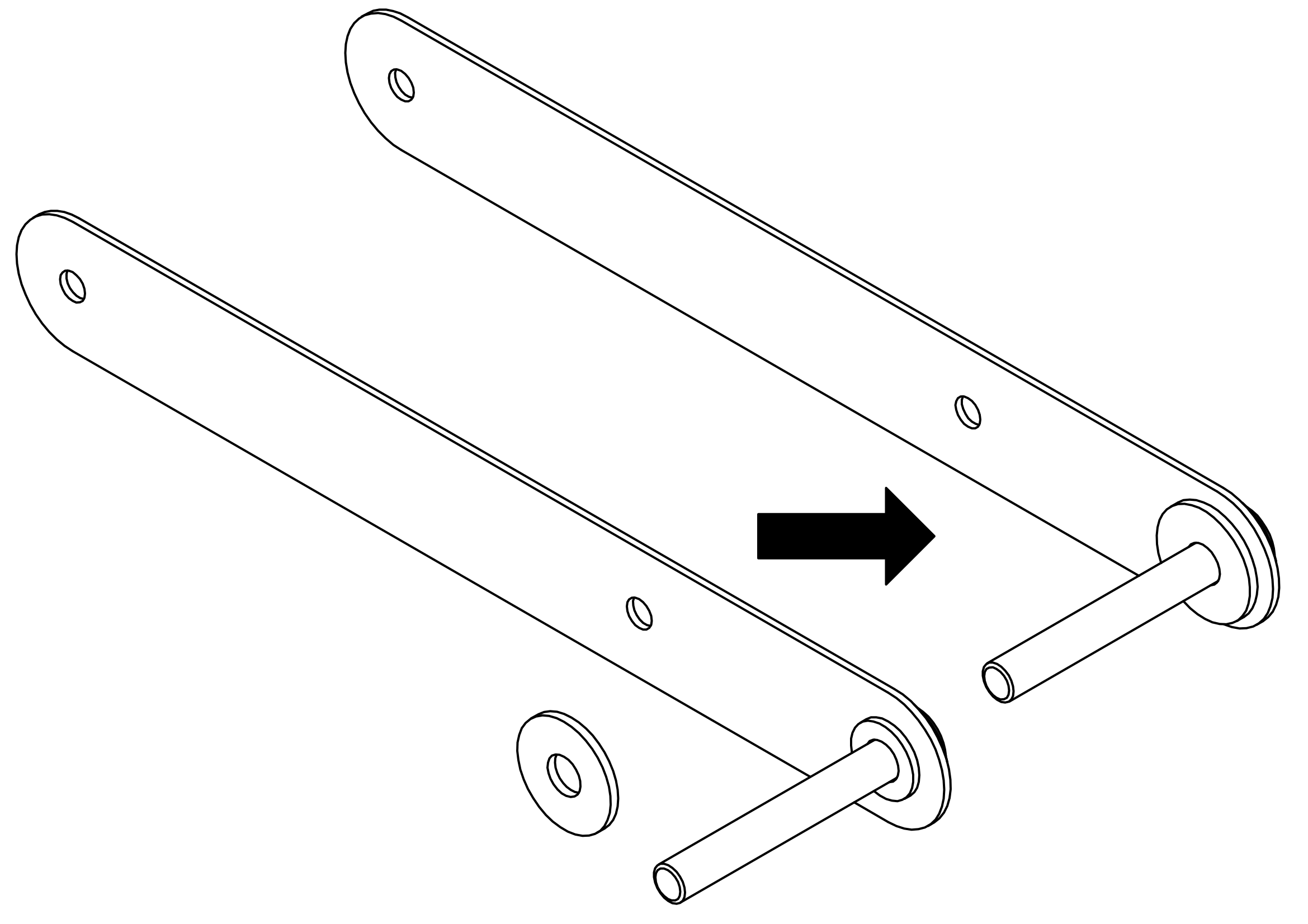
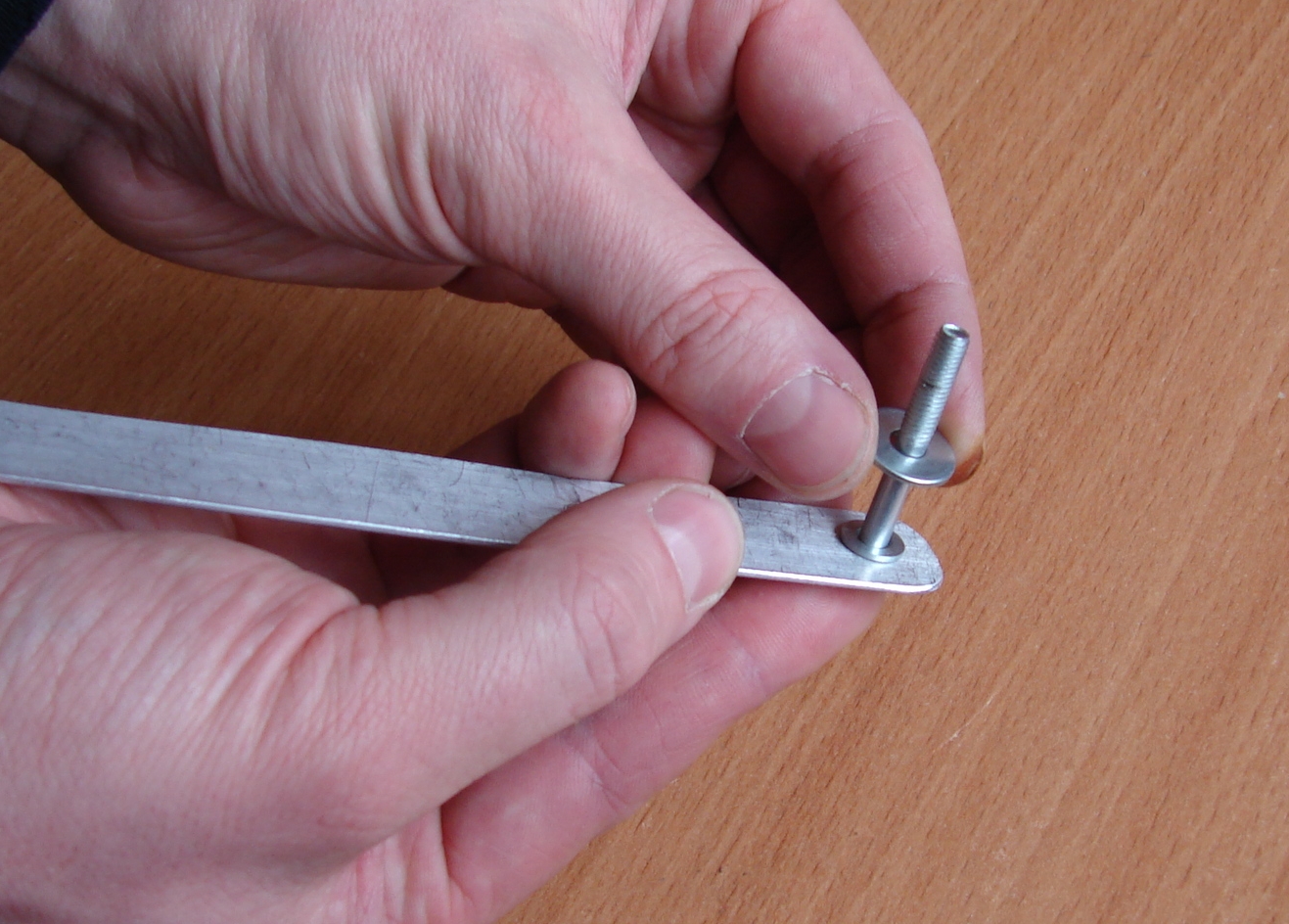
We will use two washers for each side of Roller as a slide bearings.
Assembly …
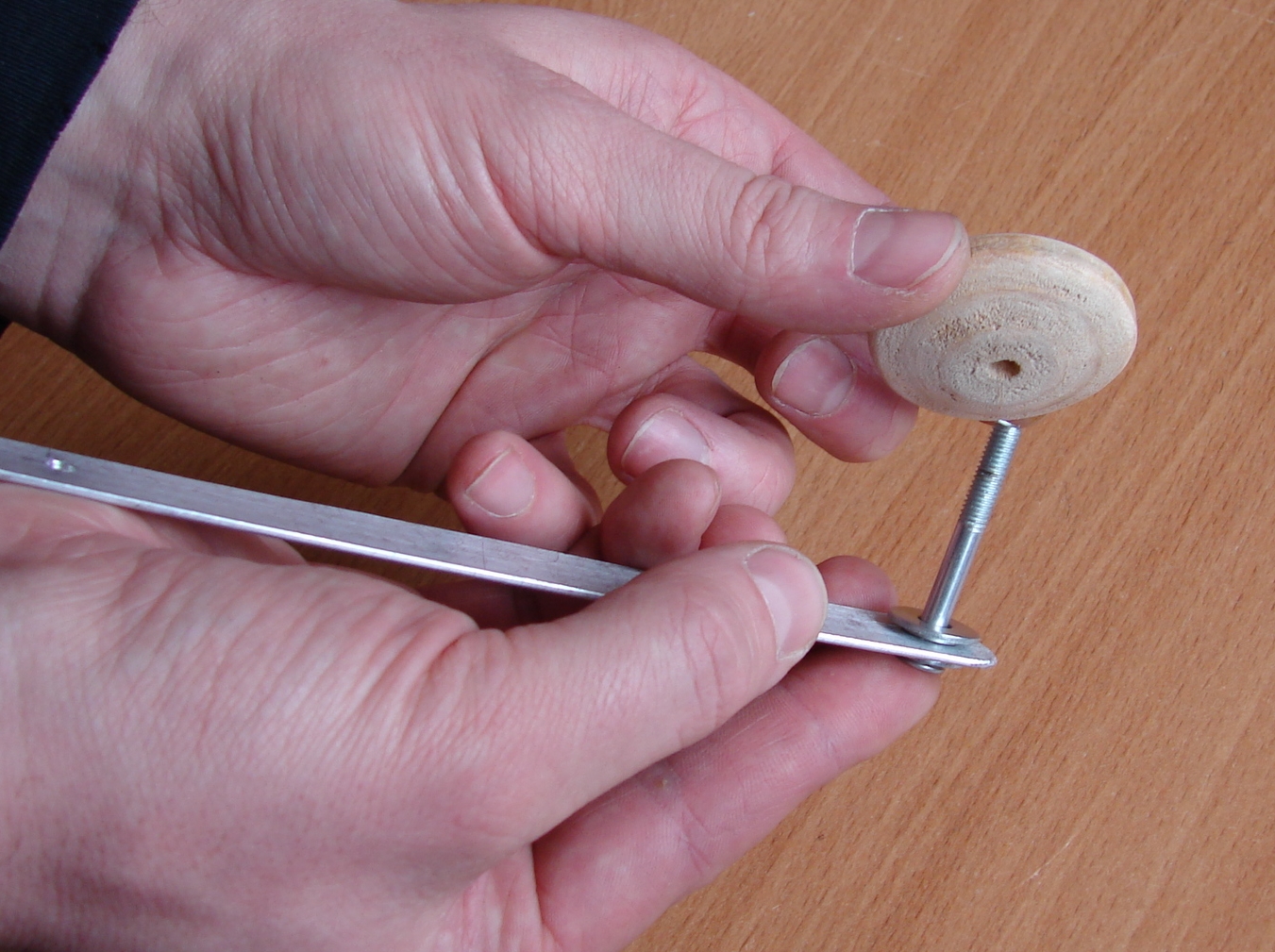
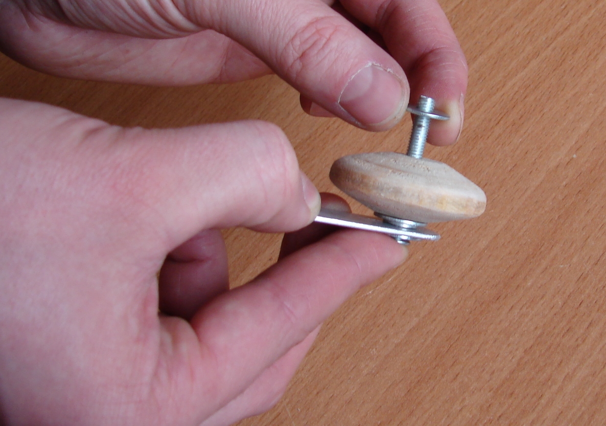
Put the Roller on the axis.
Assembly …
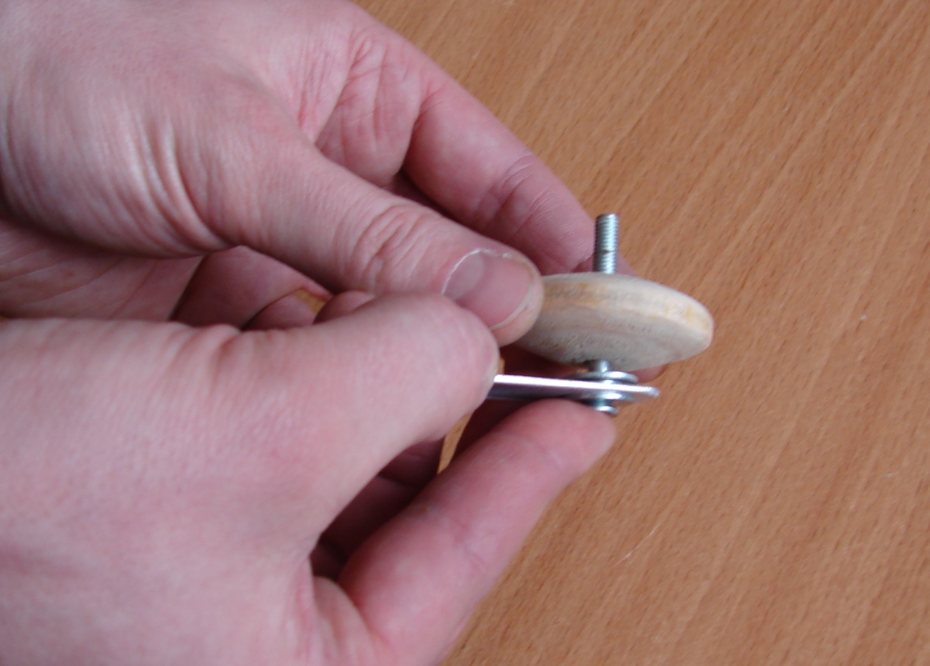
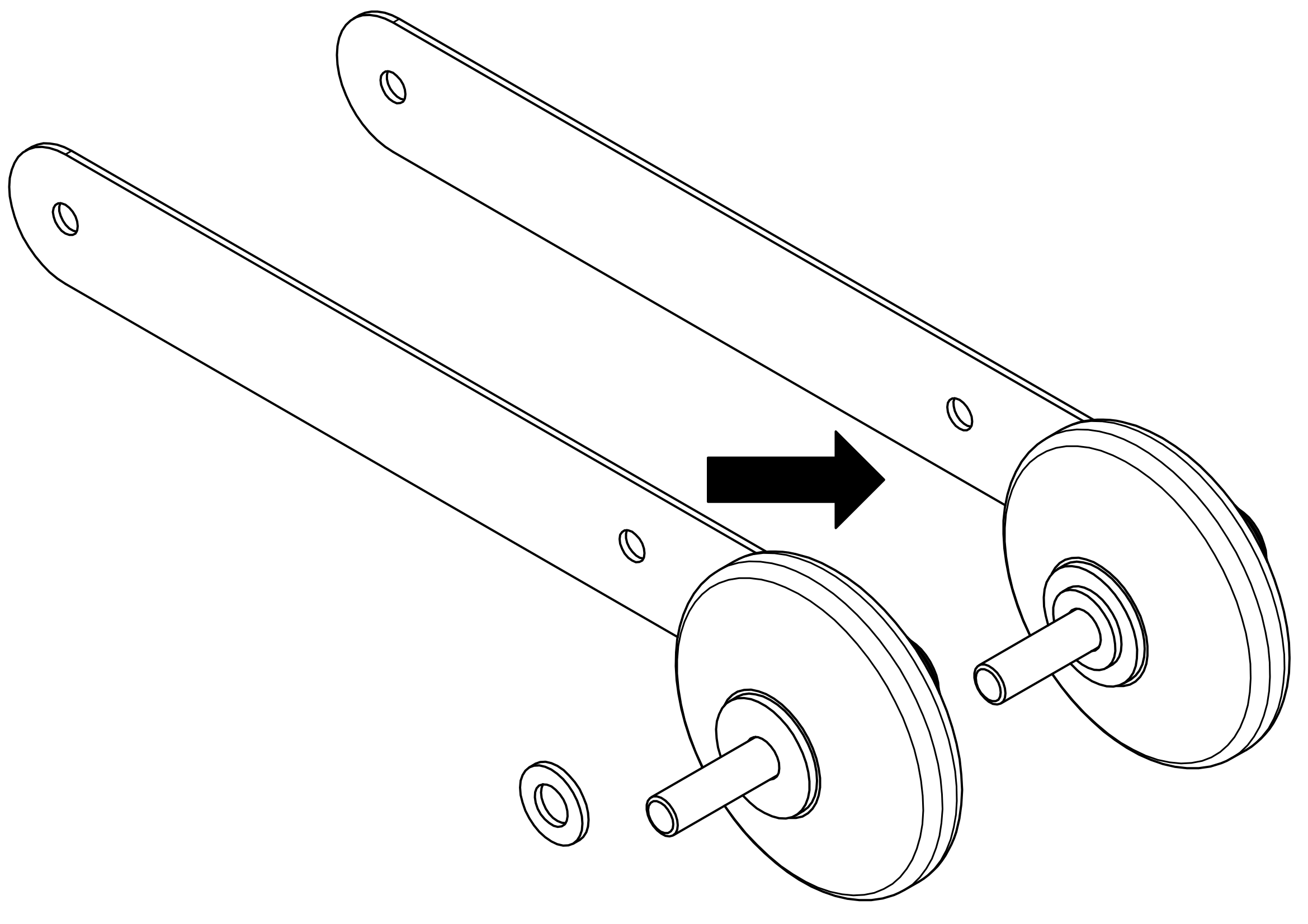
Put two washers on the other side of Roller.
Assembly …
Assembly …
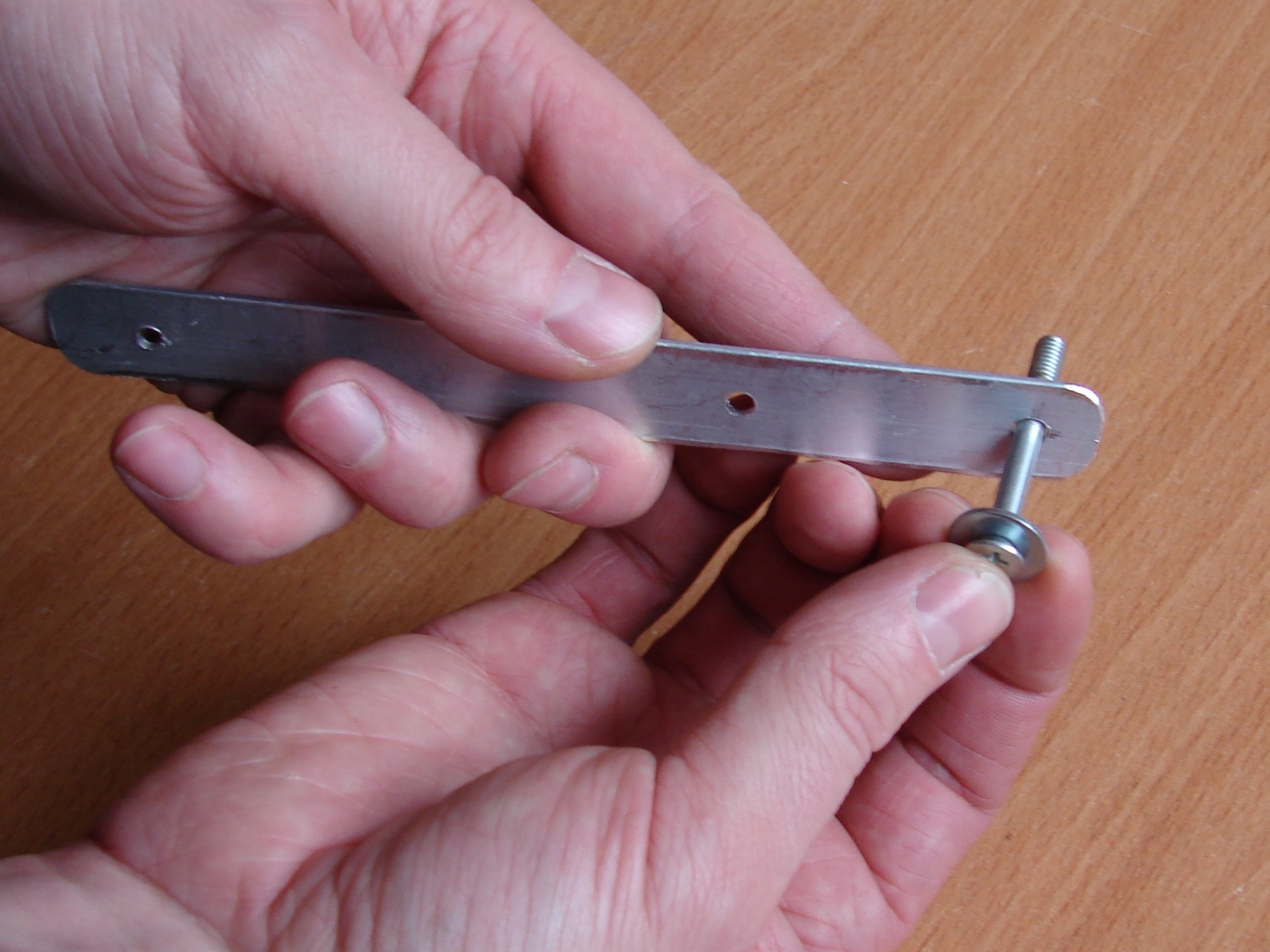
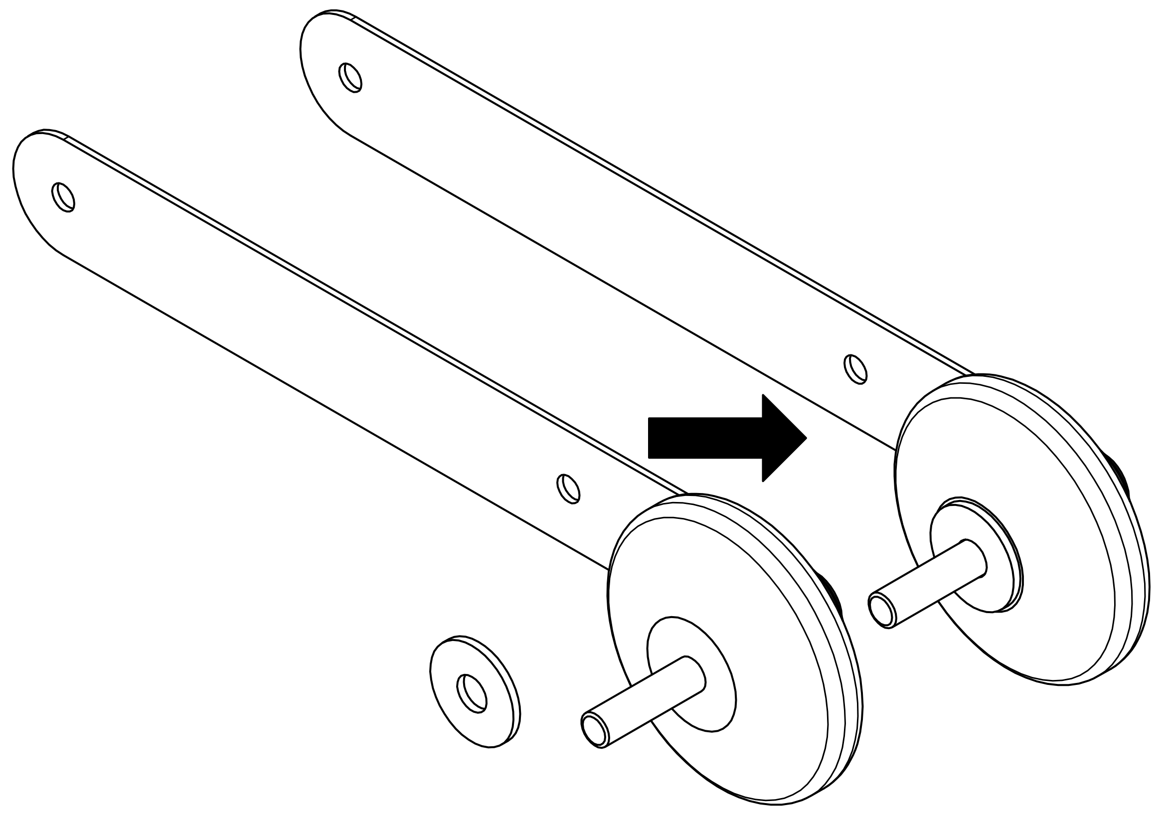
Put the second Bracket on the axis.
Assembly …
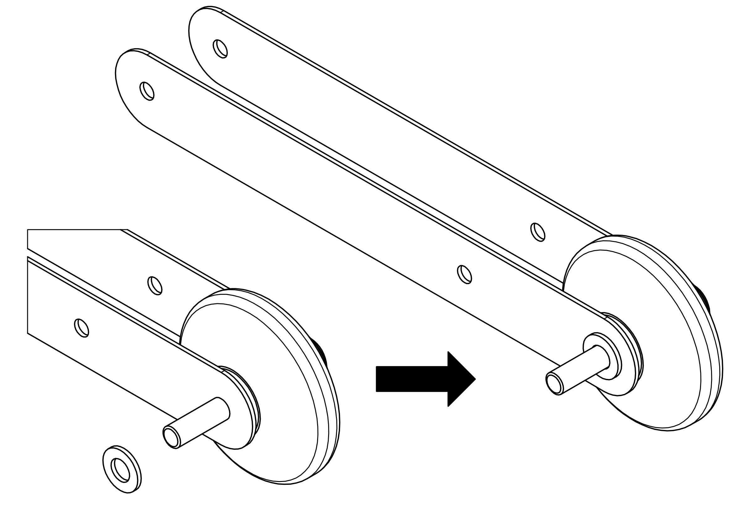
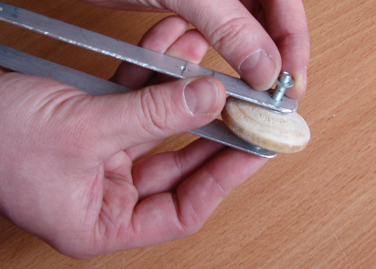
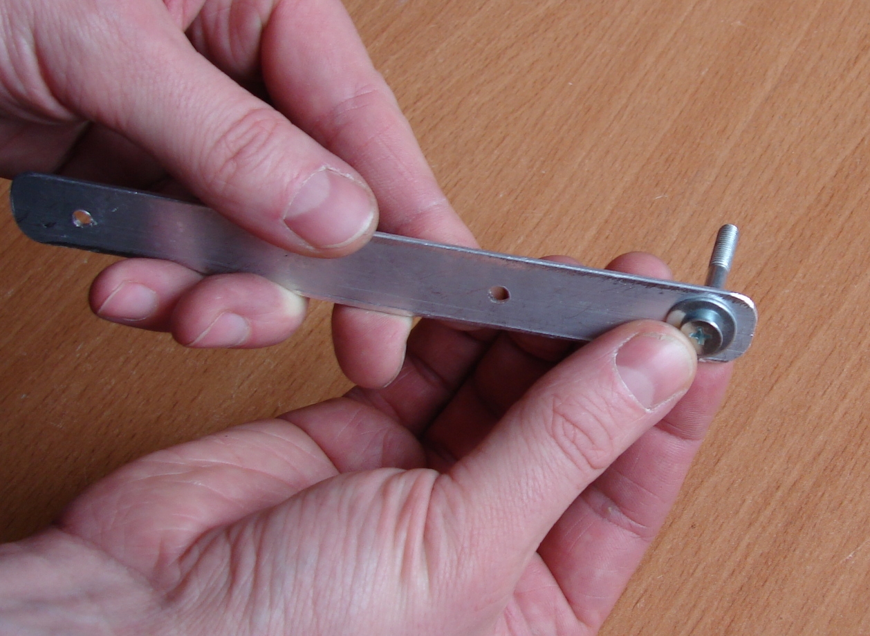
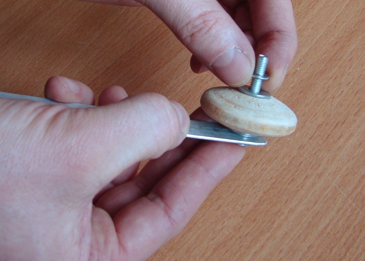
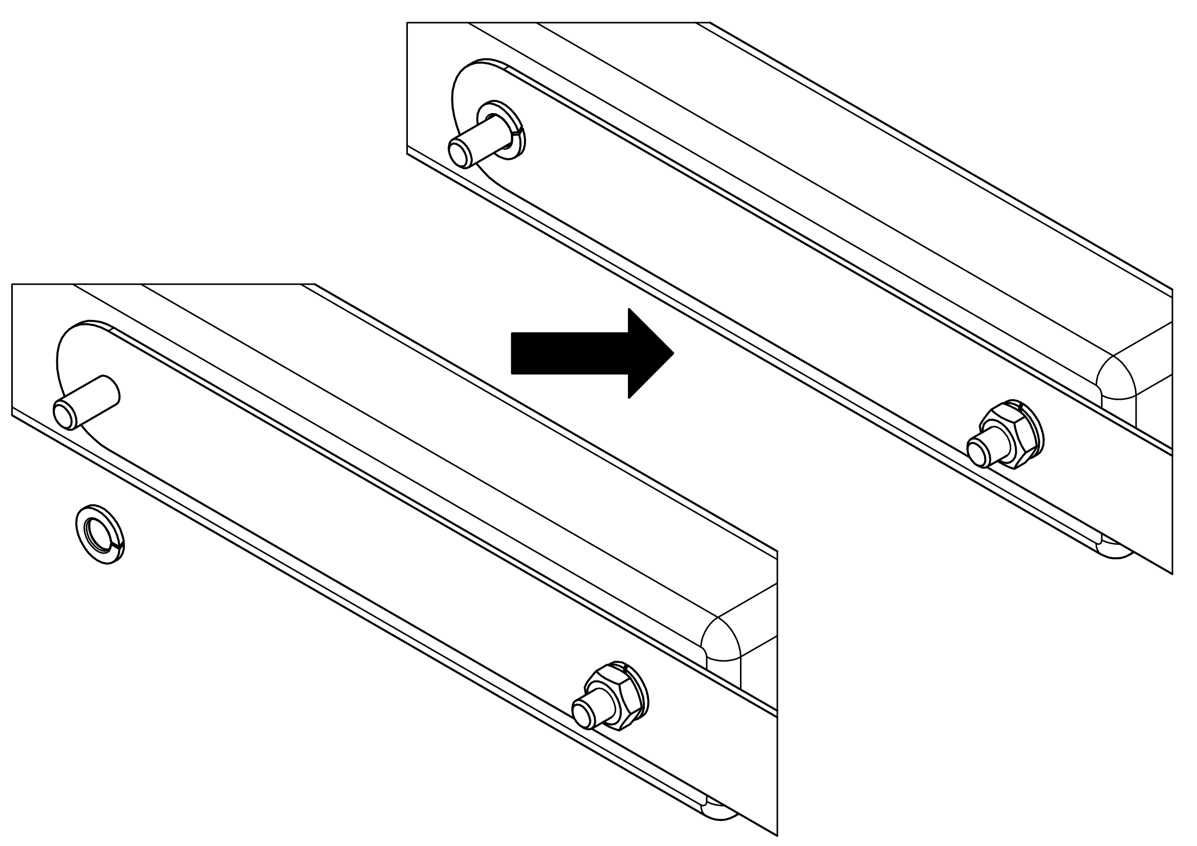
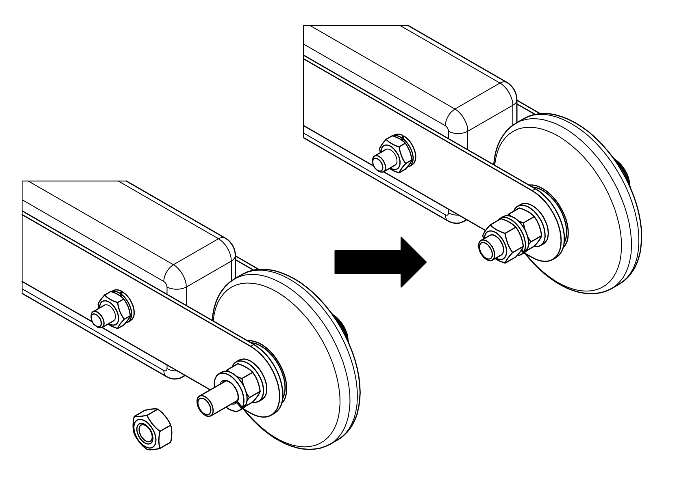
Put the additional washer on the outside surface of the second Bracket.
Assembly …
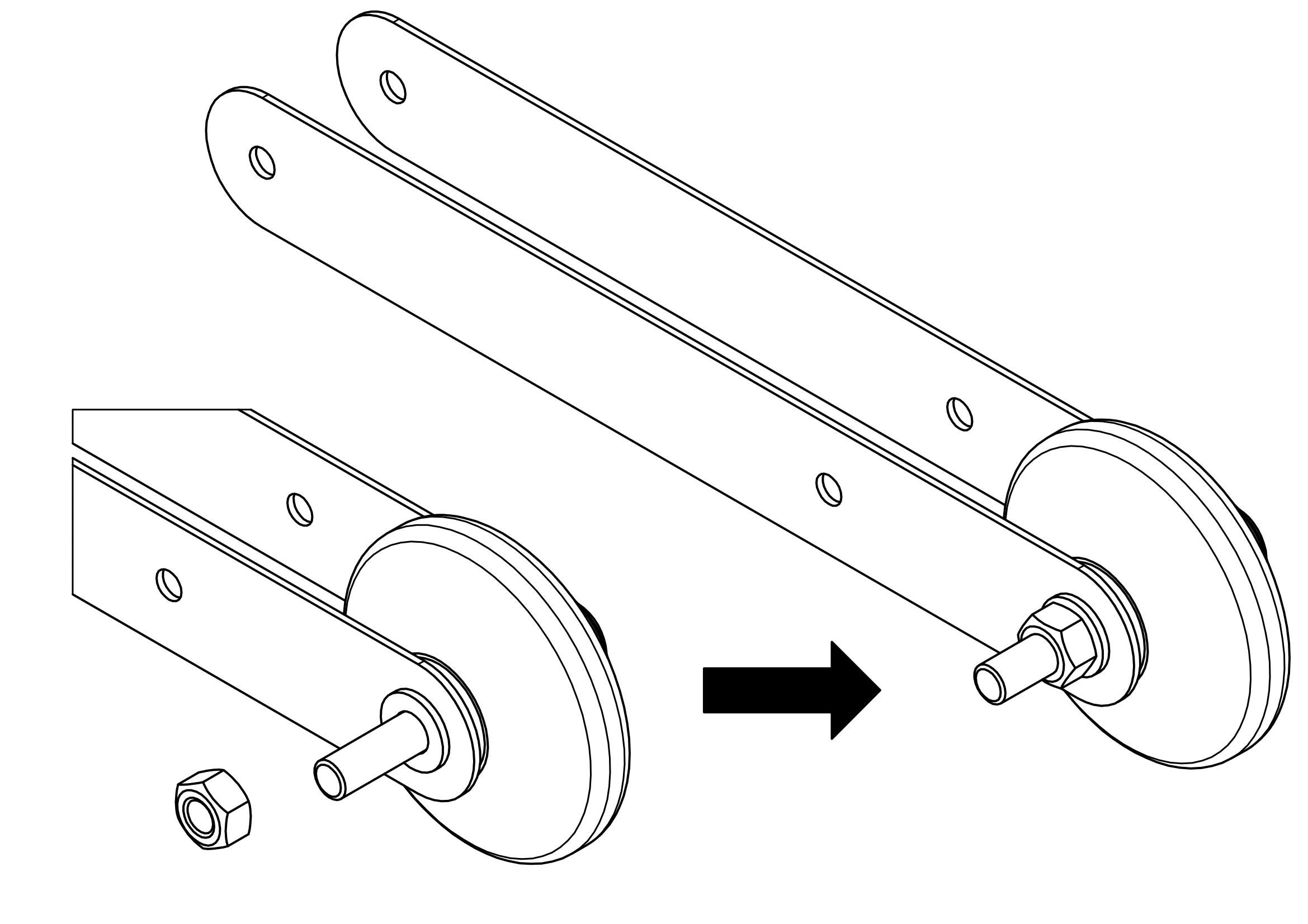
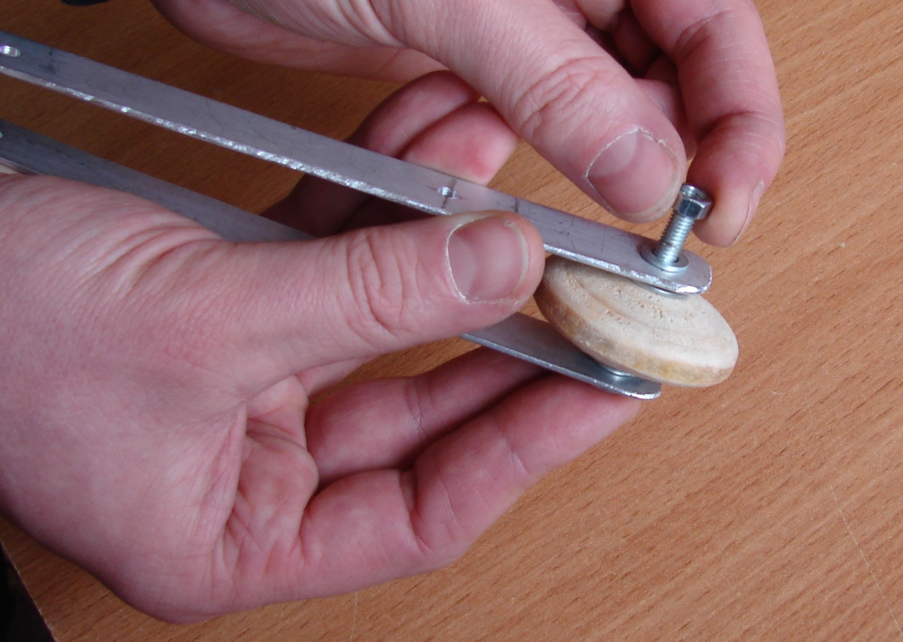
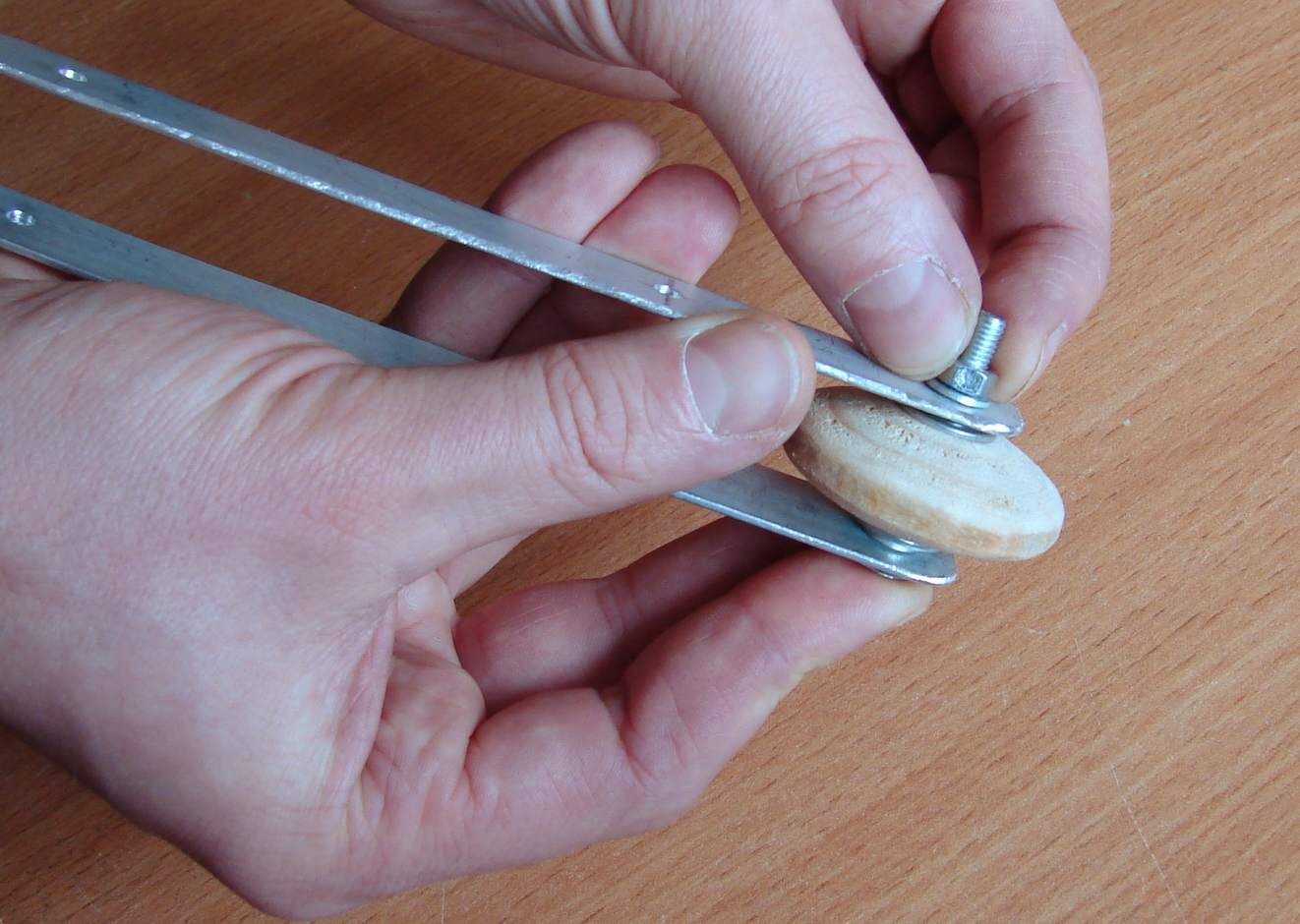
We use only one nut until the final fixation.
Assembly …
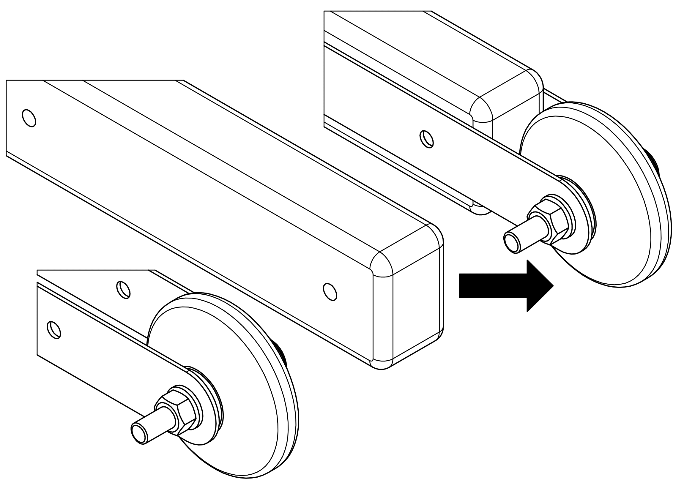
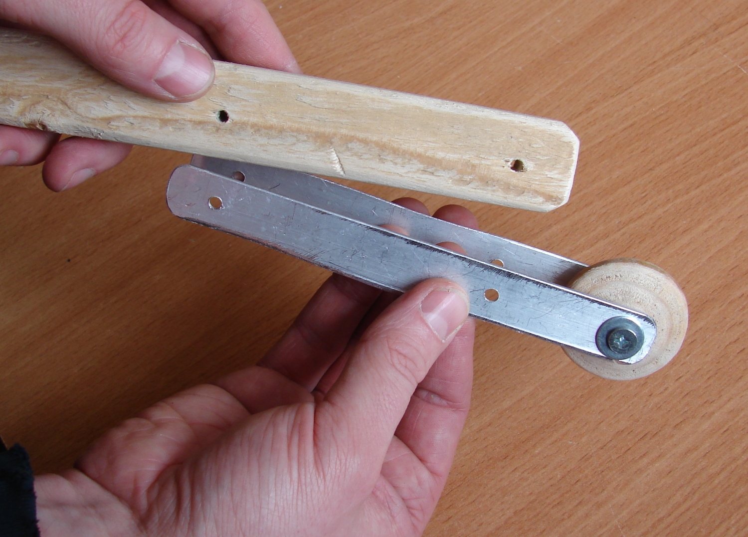
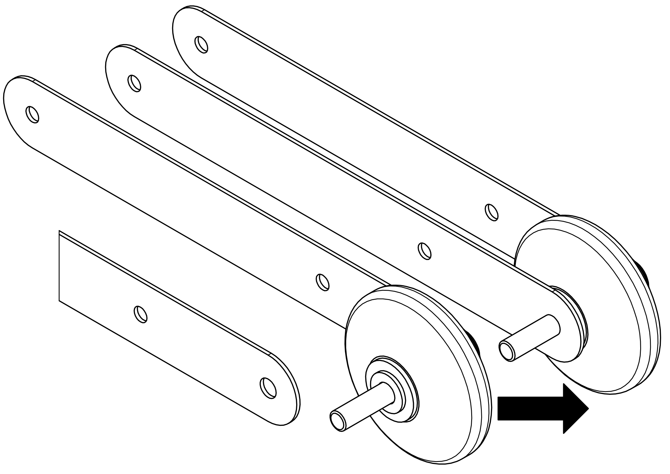
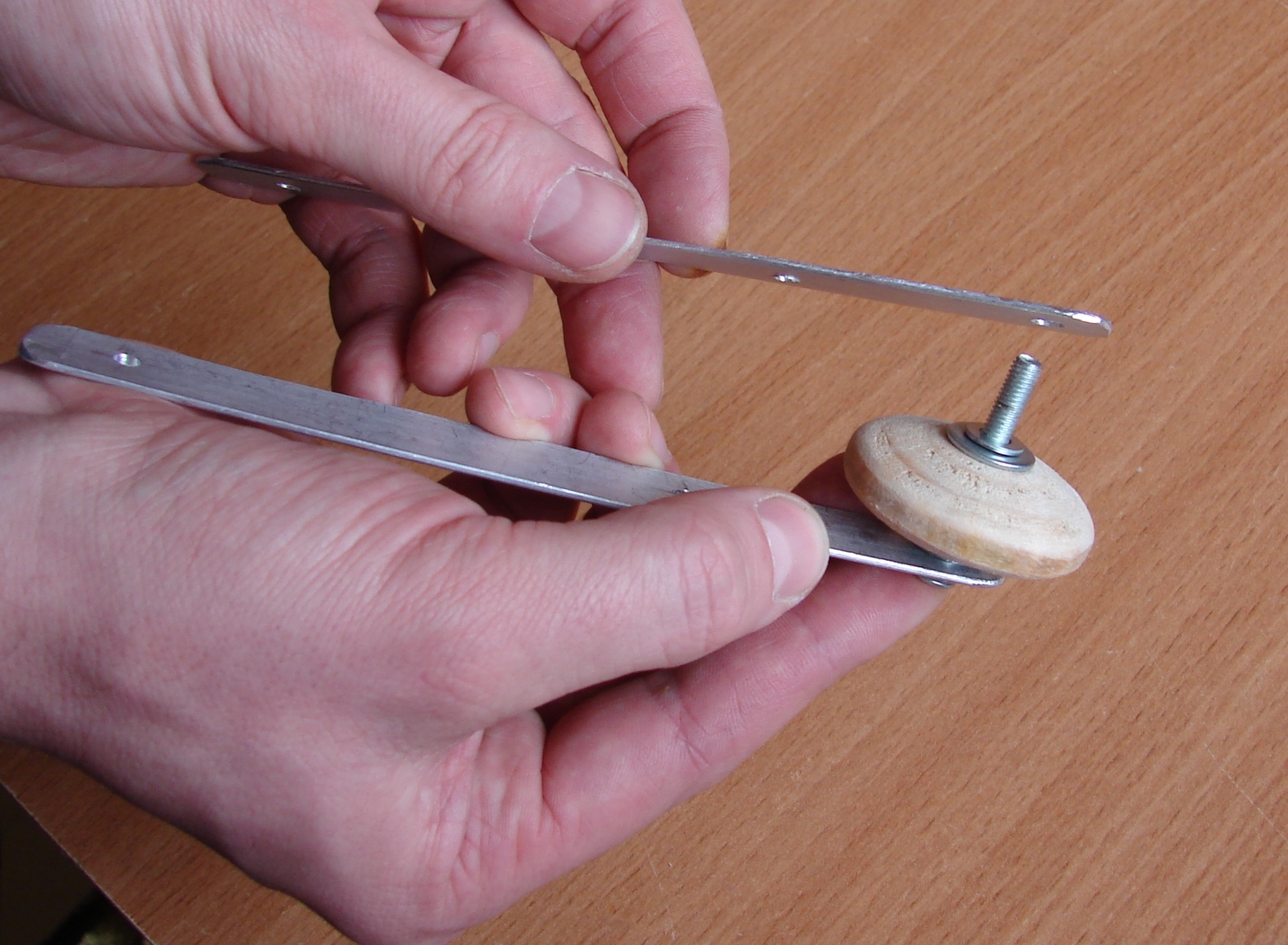
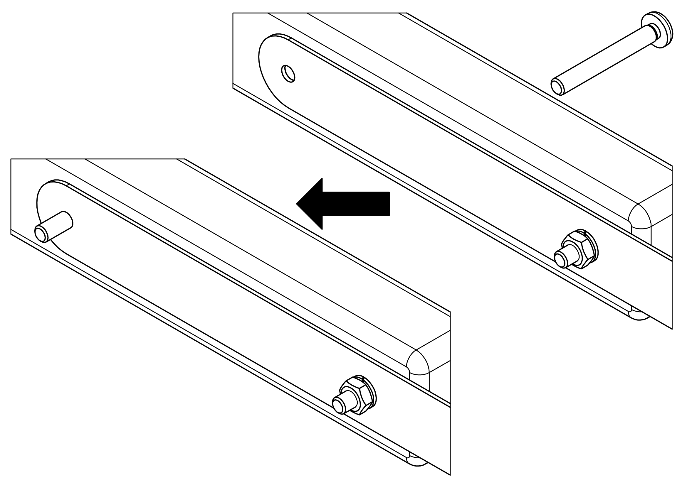
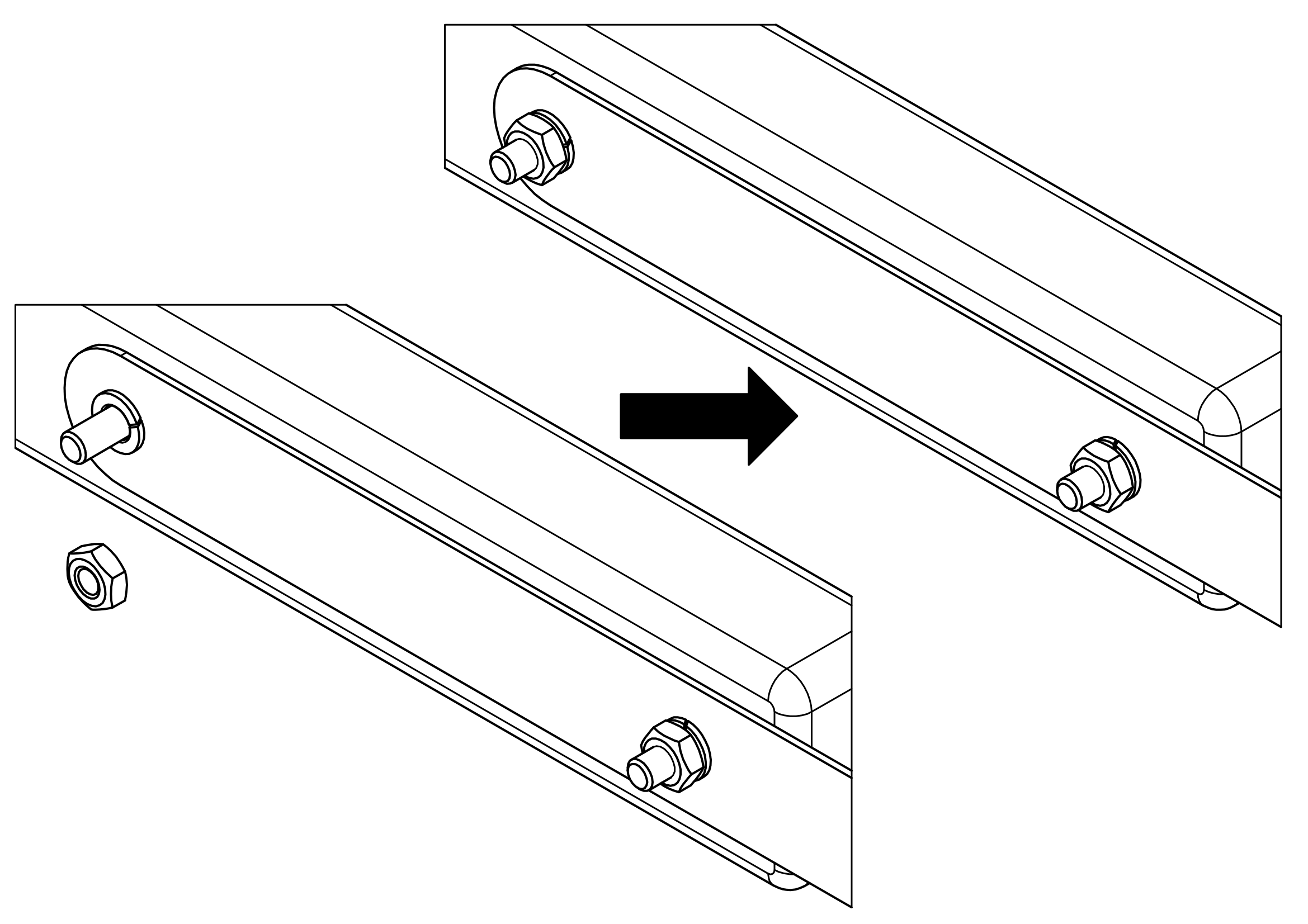
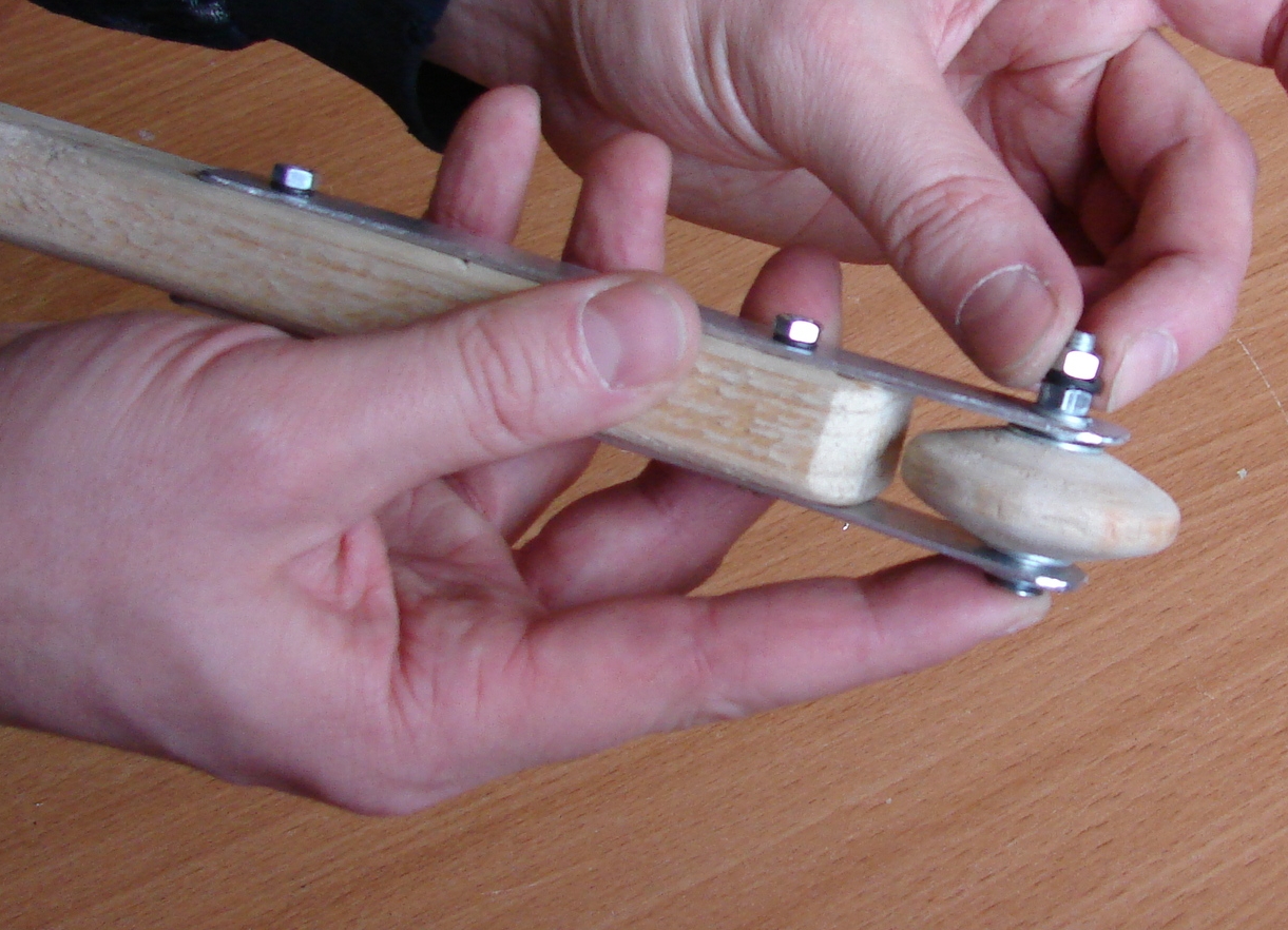
Put the Handle between Brackets.
Assembly …
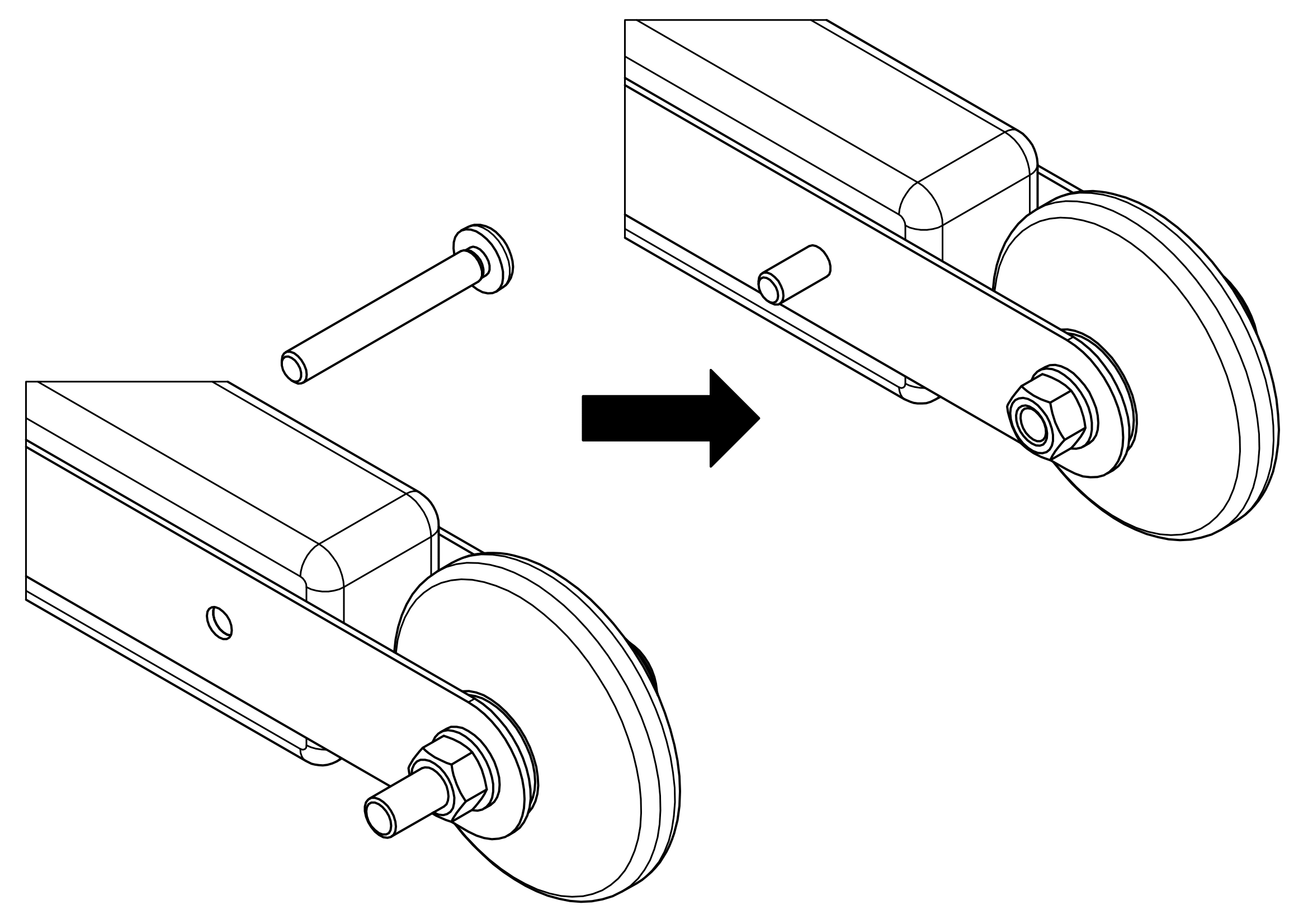
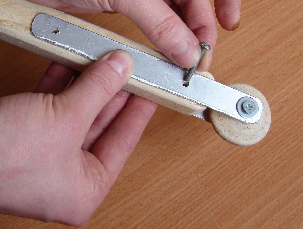
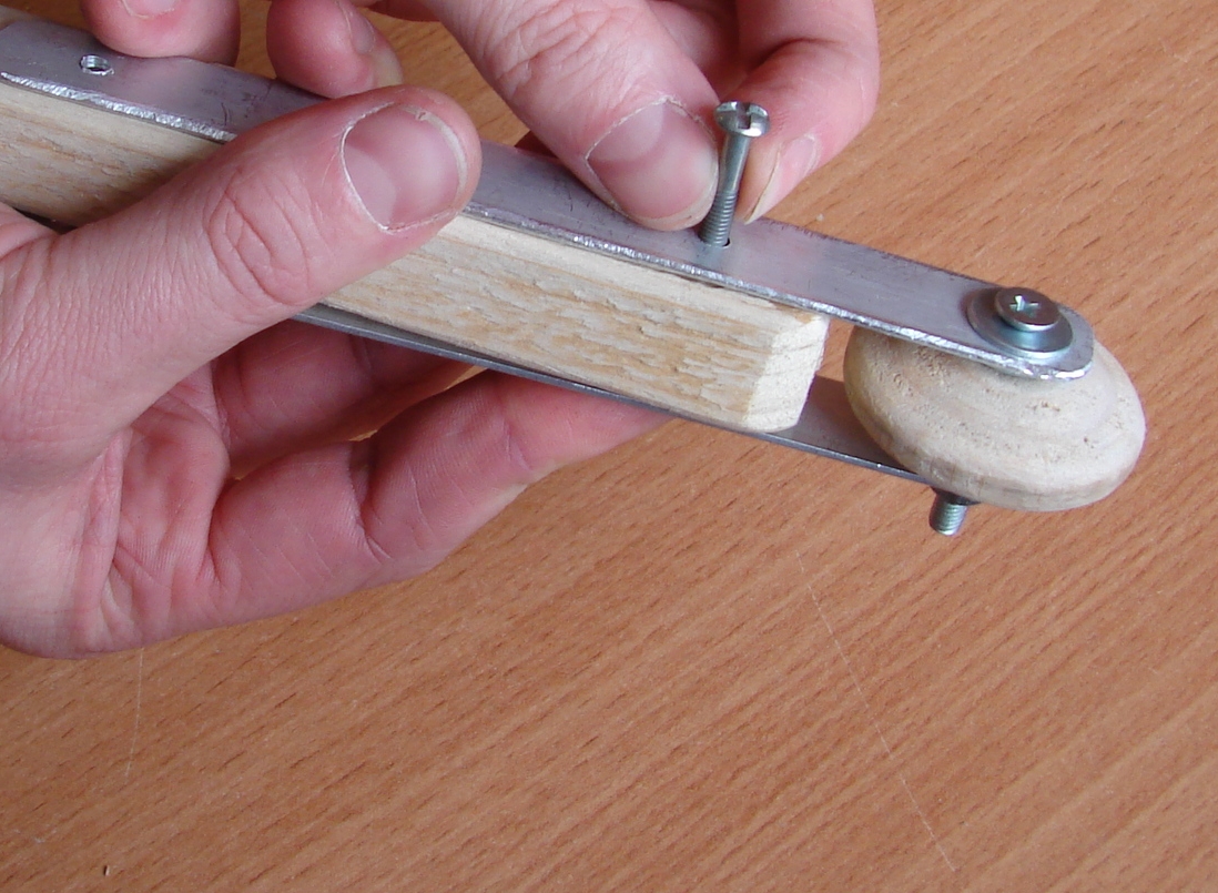
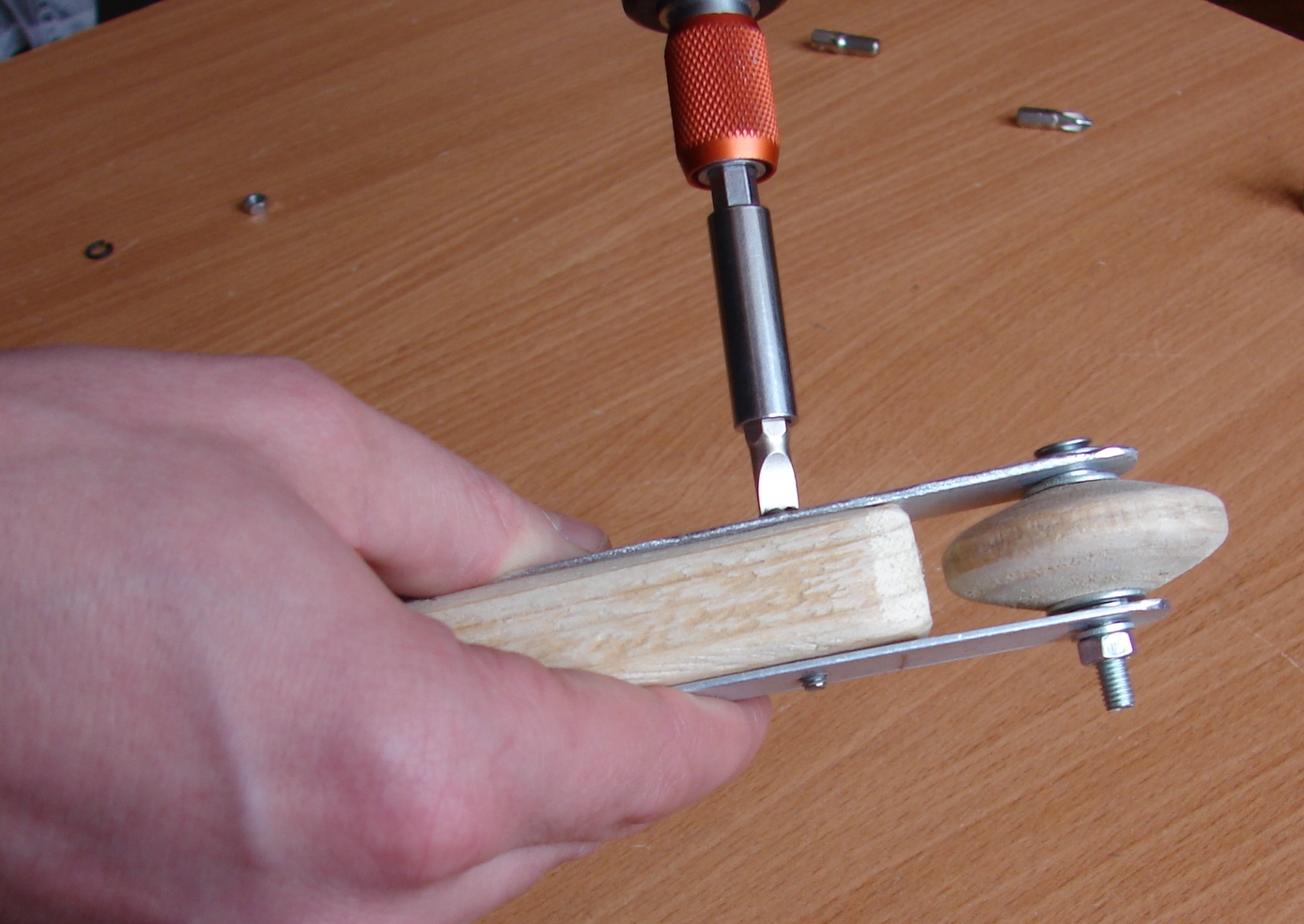
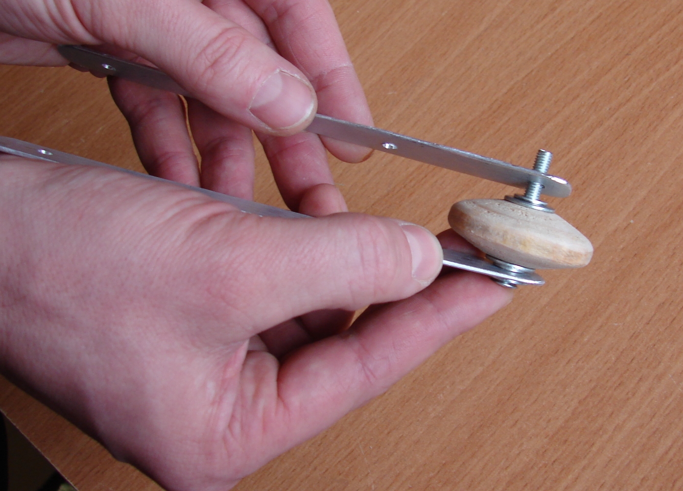
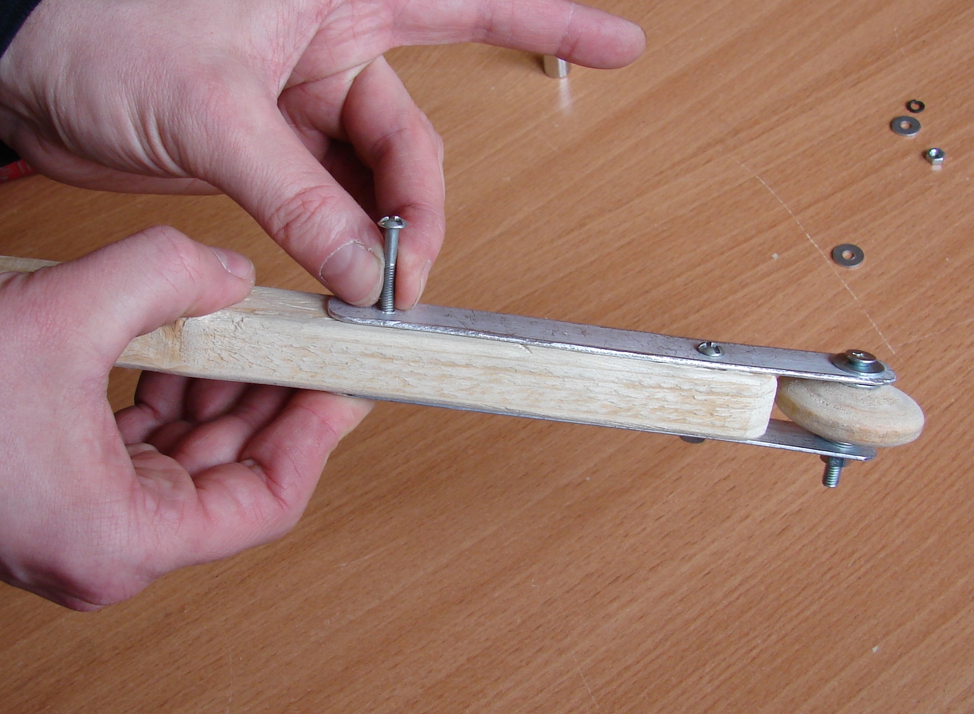
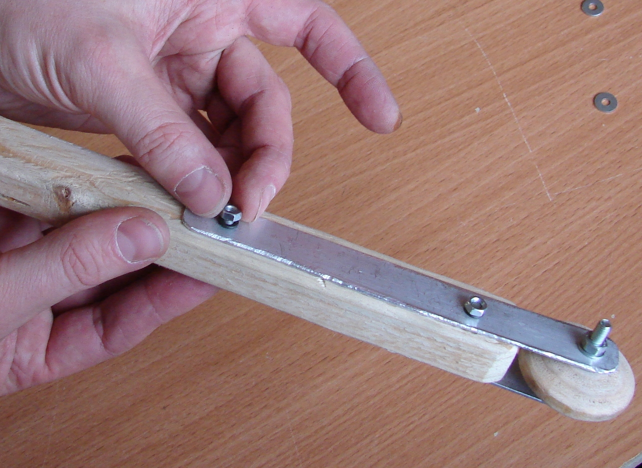
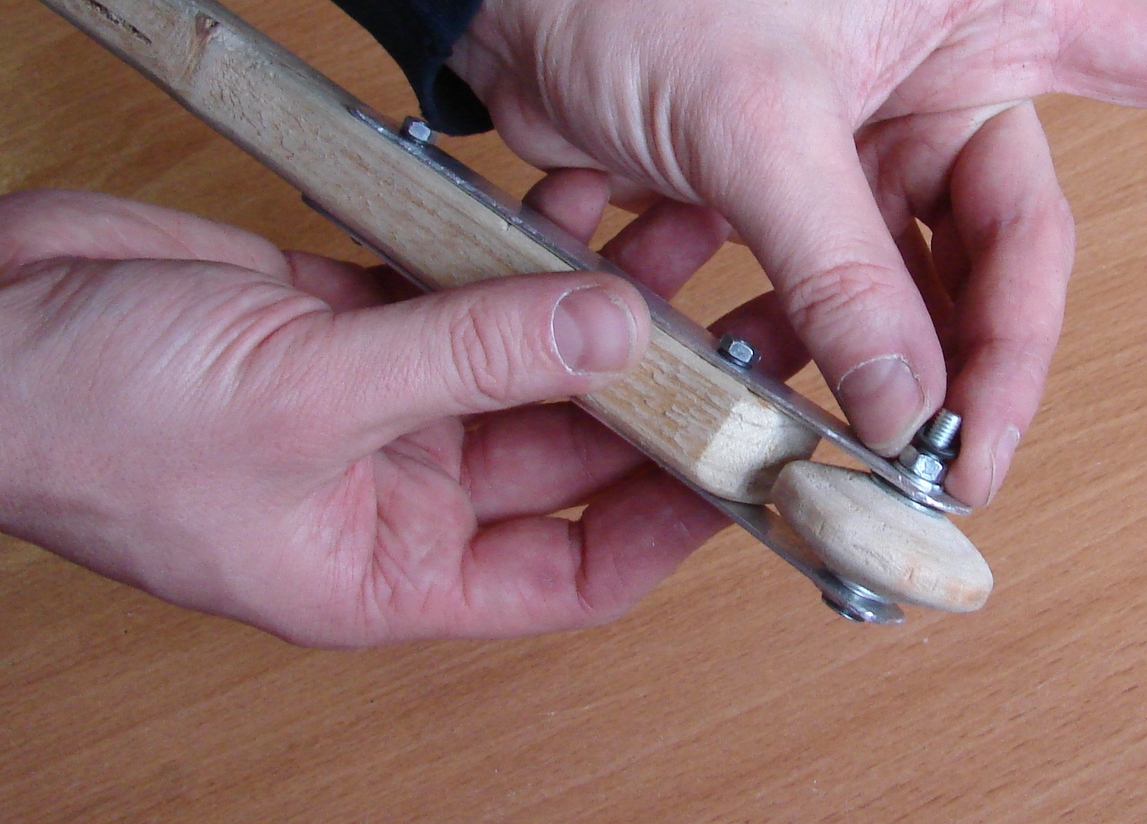
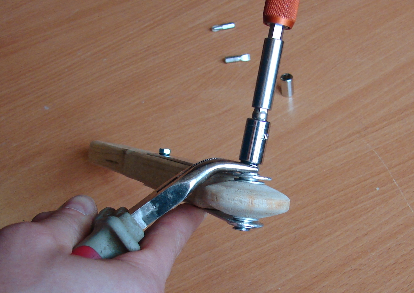
Put the first screw to fix Handle in Brackets.
Assembly …
Use the spring washer to prevent auto disassembly.
Assembly …
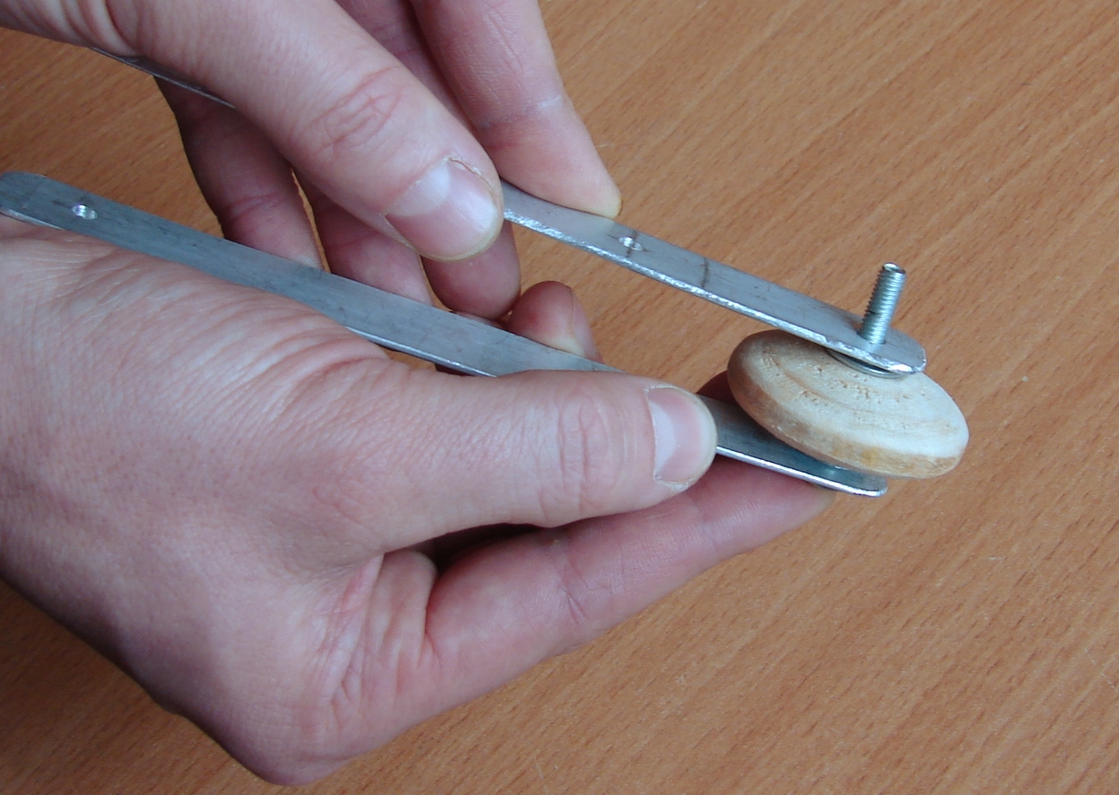
Put the fixing nut for a Handle.
Assembly …
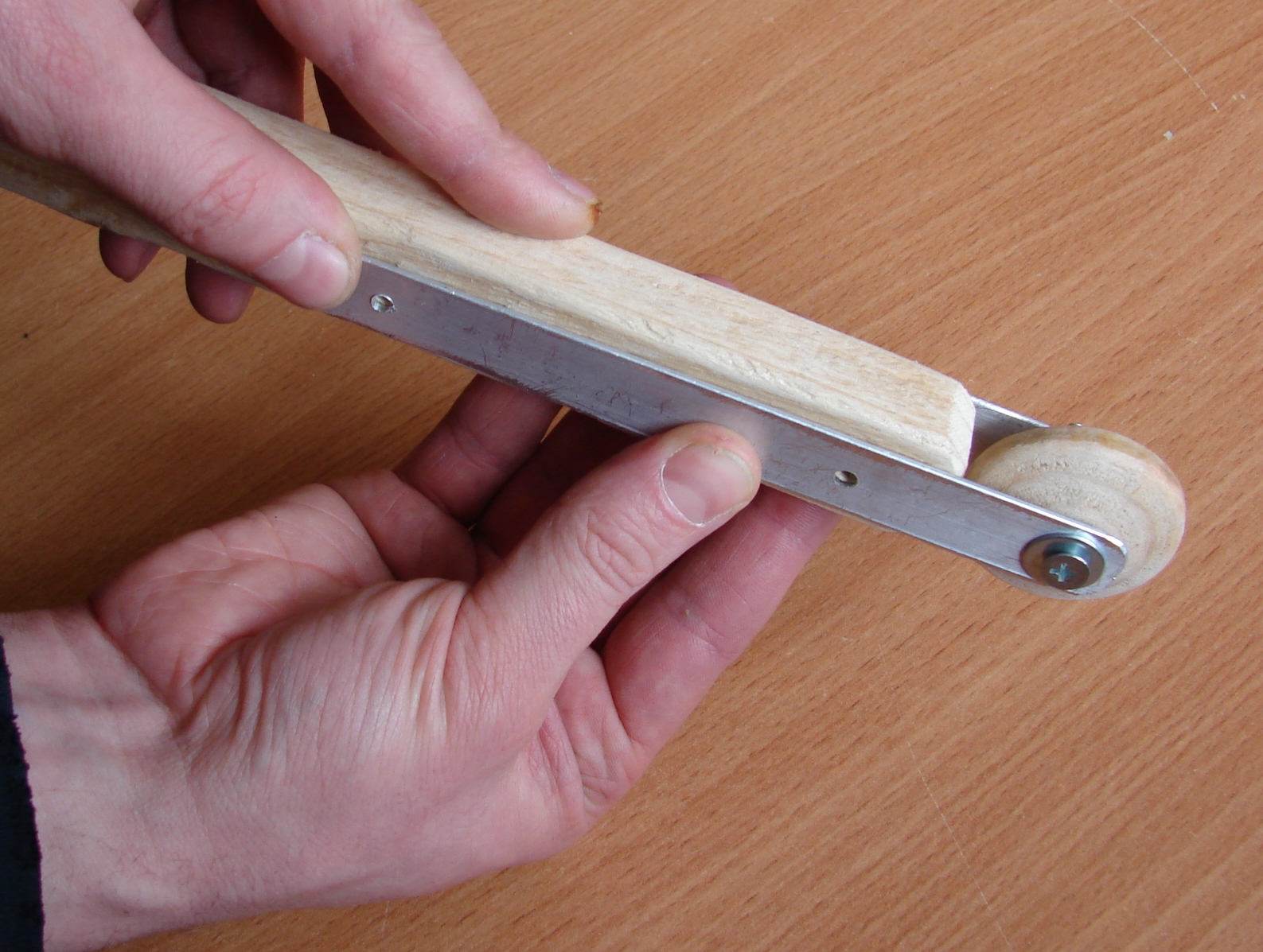
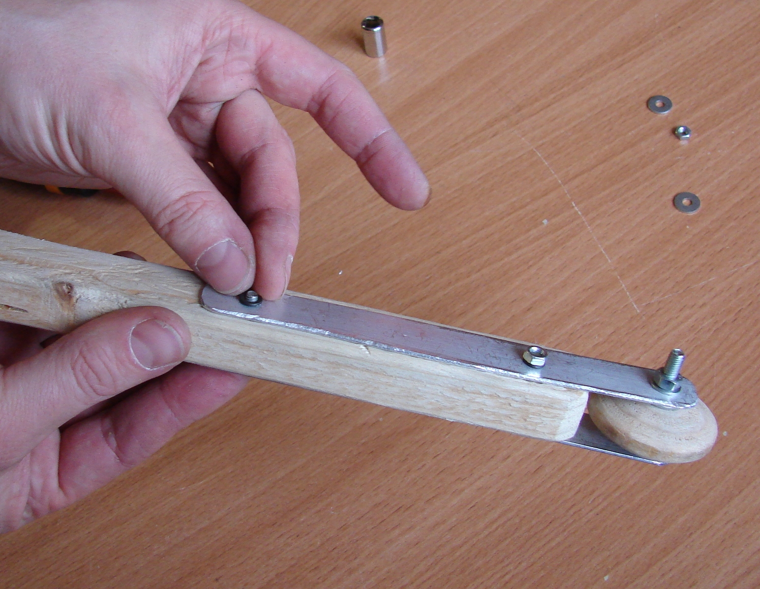
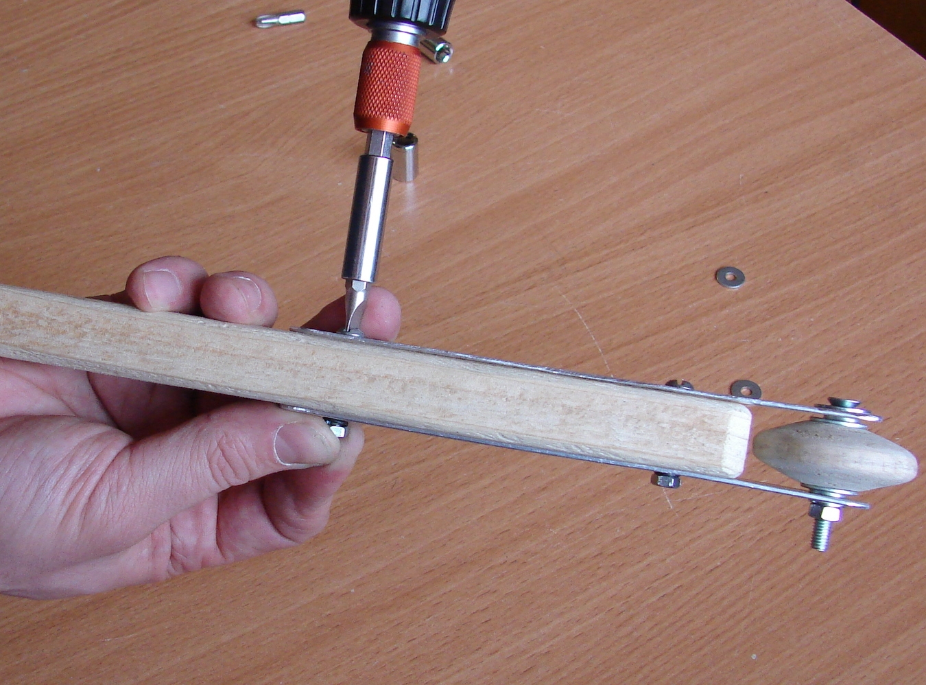
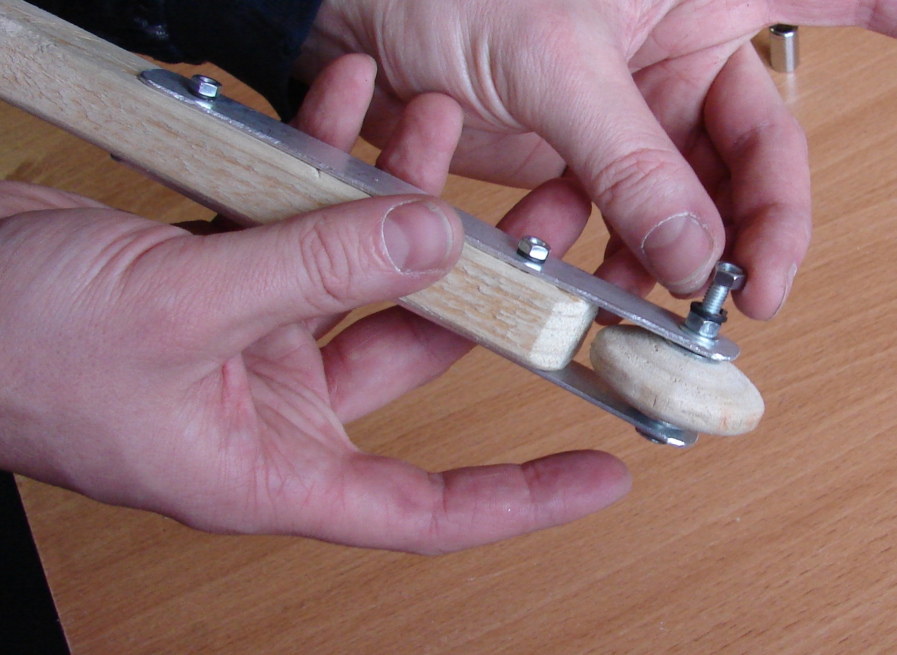
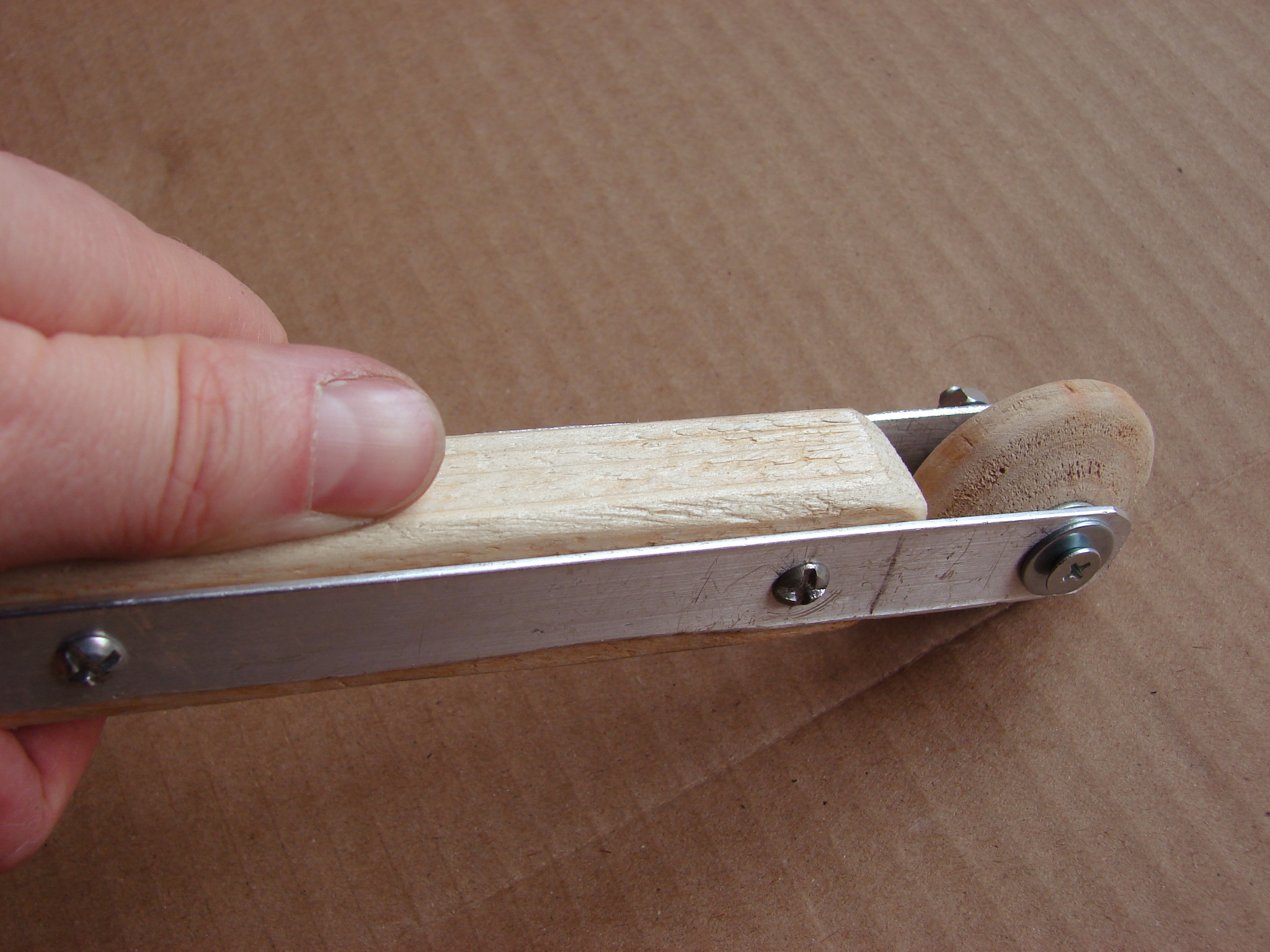
Make the same operations for the second mounting "screw-nut" subassembly on the Handle.
Assembly …
Assembly …
Assembly …
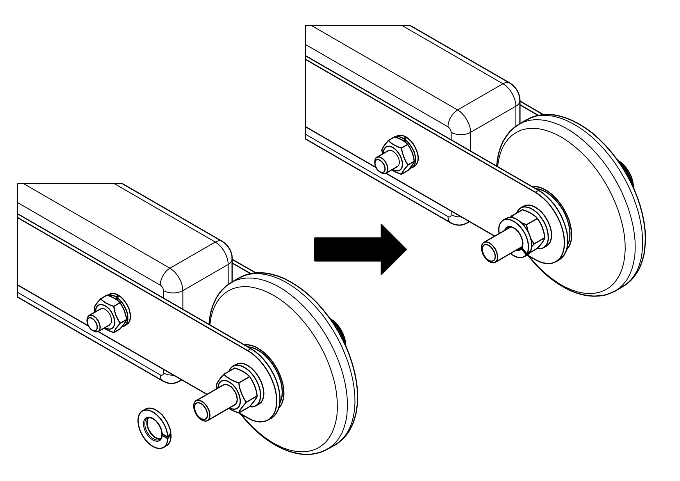
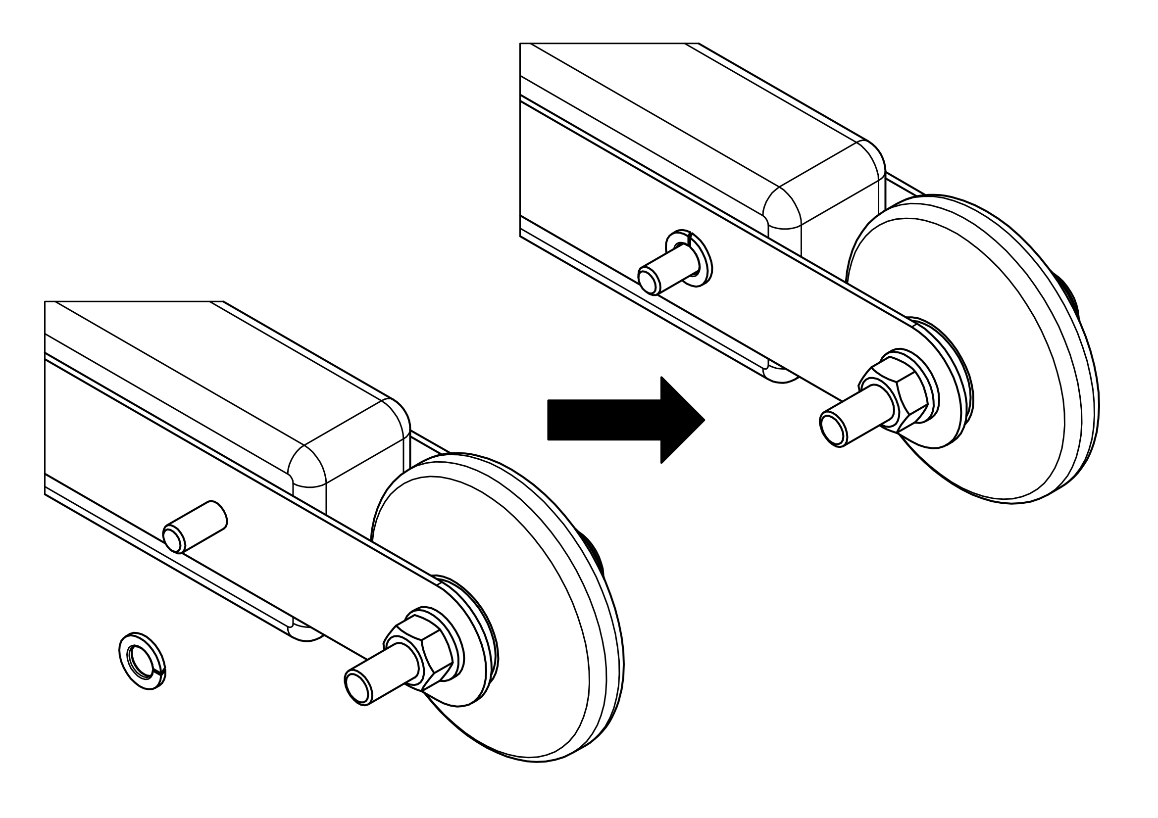
Put spring washer on the Roller axis.
Assembly …
Put the second fixing nut on the Roller axis.
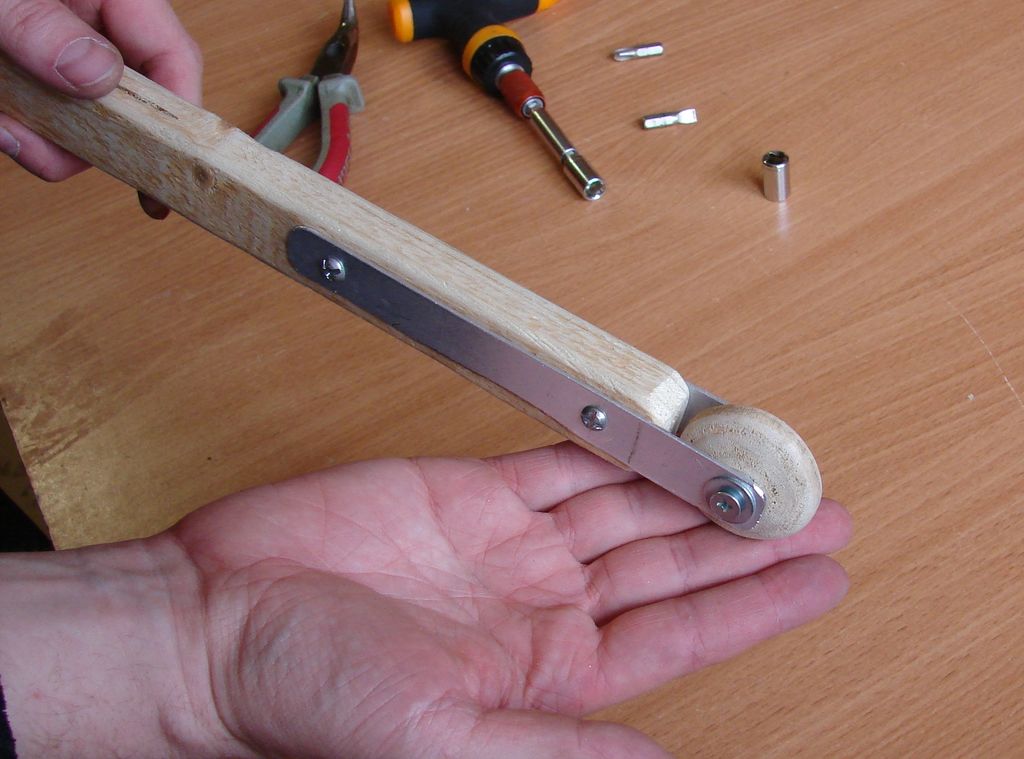
Finish
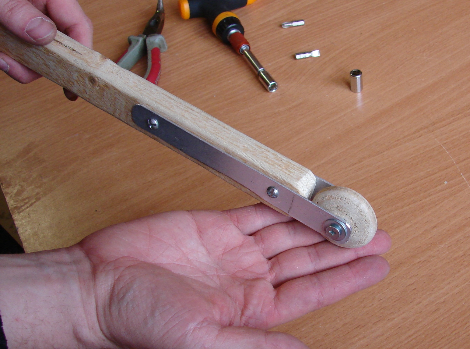
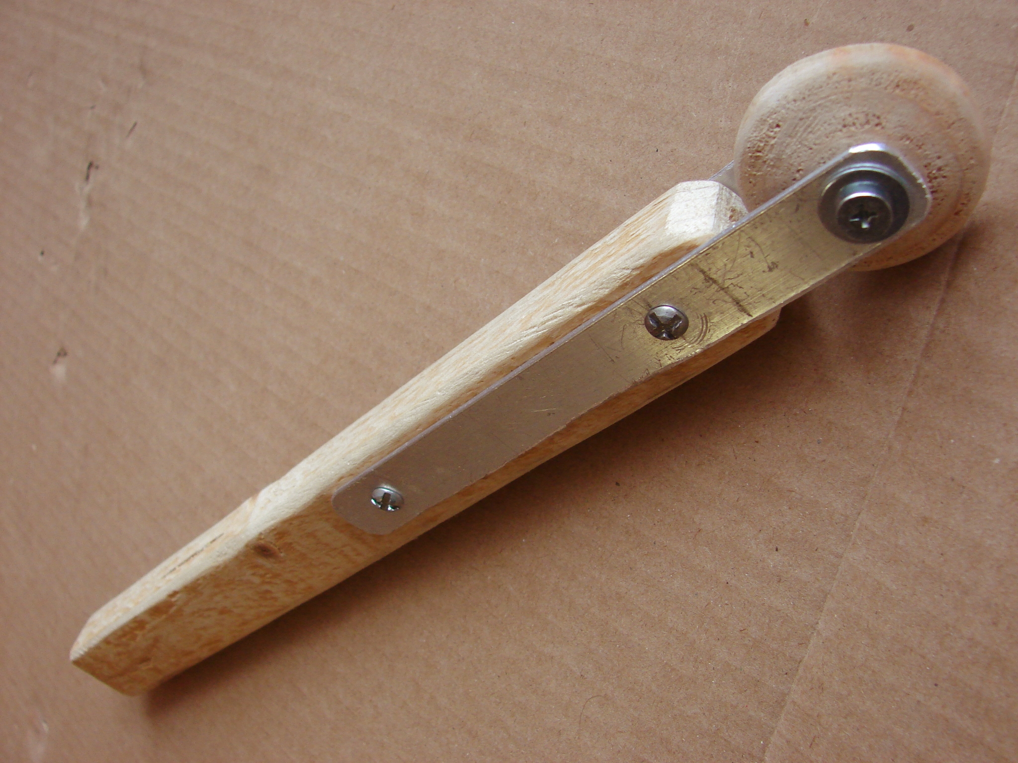
Test our new device in action.