CardVision: AI Powered Blackjack Table
by maxHowest in Circuits > Raspberry Pi
351 Views, 4 Favorites, 0 Comments
CardVision: AI Powered Blackjack Table
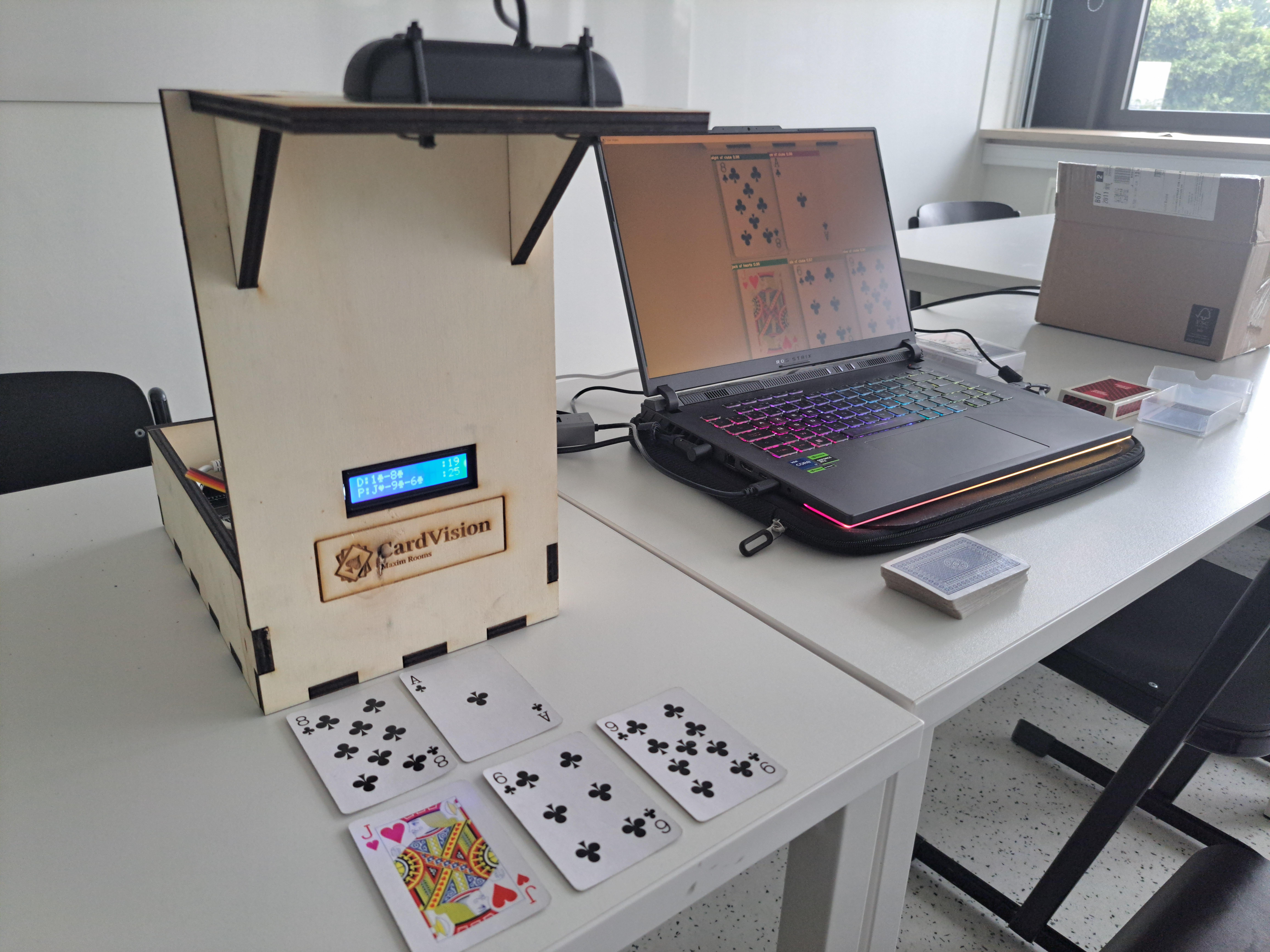
I created this project for my first year at Howest in the bachelor Creative Tech and Artificial Intelligence. The project contains a frame which holds a camera and an LCD powered by a Raspberry Pi. An AI computer vision neural network runs on a separate laptop which determines the cards at play on the table and feeds this information to the Raspberry Pi which displays it on the LCD screen.
Supplies
The Freenove FNK0054 developer kit for Raspberry Pi(not included) provides necessary interfacing and easy compatibility between the Raspberry Pi's GPIO pins and the LCD screen(included in the kit). For this project I used a Raspberry Pi 5 with 8gb of memory, a generic 1080p USB webcam and a laptop with a preferably powerful graphical processing unit from Nvidia and an ethernet cable to enable LAN communication between the Raspberry Pi and the laptop. The frame is laser cut out of 8mm thick plywood (600 by 450mm sheet) and glued together with wood glue, then the lcd is screwed into the back and the camera is attached with zip ties. Depending on the laptop all of these supplies should cost upward of €1500. Attached is a full bill of materials and costs made for the final project with links to suppliers.
Enabling AI Computervision in Python
First of all we need to be able to run the computer vision neural network on our laptop, using out graphics card to get real-time results. To do this we need the right software to handle our YoloV8 model training and running in python. The software I used is: Visual Studio Code (IDE for python), Anaconda (python kernel with GPU interface) and Cuda (Nvidia AI toolkit). When installing Anaconda don't forget to add it to the path environment variable as this will be important later.
With all of this installed we just need the right libraries installed for the Anaconda python kernel to enable the AI model to work. Depending on the version of CUDA installed you will need different versions of the libraries. These can be found here. The following code is a guideline for what installing these libraries should look like in Anaconda prompt.
# CUDA 11.8
conda install pytorch==2.3.0 torchvision==0.18.0 torchaudio==2.3.0 pytorch-cuda=11.8 -c pytorch -c nvidia
# CUDA 12.1
conda install pytorch==2.3.0 torchvision==0.18.0 torchaudio==2.3.0 pytorch-cuda=12.1 -c pytorch -c nvidia
# CPU Only
conda install pytorch==2.3.0 torchvision==0.18.0 torchaudio==2.3.0 cpuonly -c pytorch
Only one of the above lines should be entered into the Anaconda command prompt, these above include some of the most recent examples, including how to install it for a CPU only laptop (no Nvidia GPU present).
The following line installs libraries for python for loading our dataset, running our AI model and managing images and video input for the model.
pip install roboflow ultralytics opencv-python
Now the only thing you need to do to work in this kernel when running our python script is to select the anaconda3 python kernel in Visual Studio Code.
Gathering Data and Labeling
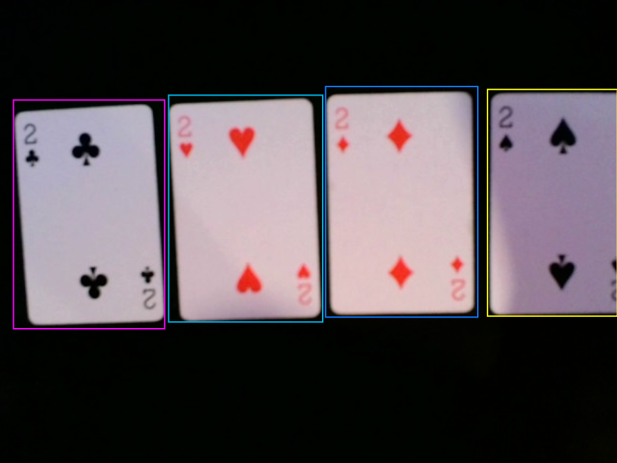
The easiest and most straightforward way to gather usable data to train our model is to take images of the objects we wish to detect and label them in Roboflow. In case of this project we need images of playing cards we wish to be able to detect with the model. To gather images you can take these manually with the USB camera for the project by pointing it at playing cards laid out on the table and taking pictures with the camera app in Windows. To speed up this process you can write a simple python program that takes pictures using the camera feed through the CV2 library. Don't worry if the resolution isn't that great or differs from picture to picture, they will all be resized in Roboflow for our final dataset.
If you have a Roboflow account you can make a new project for your dataset and upload your pictures. Next is the most arduous and time consuming part of this project, the labeling. Your uploaded pictures still need annotations telling the model where the card is and what type it is so it can learn to recognize them. Annotating in Roboflow is as simple as drawing a box around the card and typing out the class of the card(for example: "Ace of spades").
It is important to gather enough images and also have different real-world scenarios for the cards. This includes taking pictures when it's darker or when it's brighter in the room at all kinds of different angles. The quality and wide range of pictures in the dataset will determine the performance of the detection model.
Downloading Dataset and Training Model
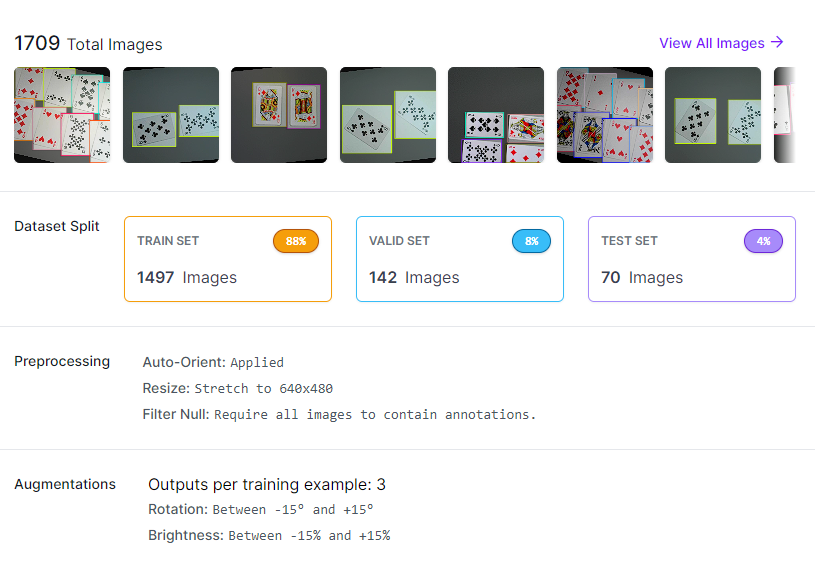
To be able to download the dataset we need to create a version in Roboflow. There you can choose how to alter the images and filter out any empty images, as well as applying augmentations to images to create a more robust dataset.
The default image size for yolov8 models is 640x640 pixels, so I chose to stretch the images to the closest resolution while staying close to the original aspect ratio. For augmentation I went with a slight rotation (+-15°) and a slight darkening or brightening of the image (+-15%) to make the dataset more robust in cases when cards aren't perfectly aligned vertically and when the lighting is different.
Once the dataset version has been created you can export it from Roboflow and get the download code to copy paste into your python or Jupyter notebook script. This will download the dataset to your current working directory.
To begin training the model is as simple as modifying and running the following code snippet:*
from ultralytics import YOLO
import os
# Training model

def main():
    base_dir = os.getcwd() # Current working directory
    # Construct the path to the dataset configuration file
    dataset_path = os.path.join(base_dir, "dataset_folder?", "dataset_name", "data.yaml")

    model = YOLO(model="yolov8m.pt")
    # In case of slow training you can use yolov8s instead of m to reduce complexity of the neural network
    model.train(data=dataset_path, epochs=100, imgsz=640, verbose=True, batch=-1)
    model.val()
    model.export()

if __name__ == '__main__':
    main()
This will train the model using the dataset we created in Roboflow and export the results such as validation, metrics and the weights for the neural network to a folder called runs(the file path is printed when the model finishes training).
*Training can take up to a couple hours depending on the hardware at your disposal. (My medium model finished training 100 epochs with 640p pictures in a little over an hour on an RTX4060)
Loading and Running the Model for Live Detection
When you have your trained model you can check out its performance and evolution through training in the runs>train folder through the confusion_matrix_normalized.png. This is a matrix that shows how many of the predictions made by the model in testing were correct. If the largest amount of predictions lie on the diagonal of the matrix that means the predictions were mostly correct and the model is working correctly.
The following code snippet will load in the model to be used in a separate script.
# Loading model
import os
from ultralytics import YOLO
# Setting directory for weights
base_dir = os.getcwd()

# Construct the path to the best.pt weights saved from the trained model
weights_path = os.path.join(base_dir, "runs", "train", "weights", "best.pt")

# Loading best model
model = YOLO(weights_path)
The next step is to use this model to apply prediction to an image in python.
# Make a prediction

path = r"test_image.jpg" # Change this path to link to a static image
result = model.predict(path)
result = result[0] if isinstance(result, list) else result
result.save("pred_img.jpg")

from IPython.display import Image
Image("pred_img.jpg")
This code snippet will apply the model to a static image and show the resulting predictions in python.
If we can predict correctly on an image we can start reading live camera images from our webcam and feed it through our model continuously.
This code is more complicated because I manually extracted values from the predictions made by the model and created a function to draw the bounding boxes with label(class + certainty%) from the resulting prediction.
I attached this script to this step to be available for download, you can manually alter the confidence threshold before the prediction is shown on the image (meaning the model has to be x% certain of the classification).
Running this script uses a live feed from your webcam opened with the CV2 library and resizes it to 1920x1080p, applies prediction on the live imaging and shows them as soon as the prediction finishes. There is an fps counter included in the top left corner to show how many frames are handled per second.
Downloads
The Connection With the Raspberry Pi
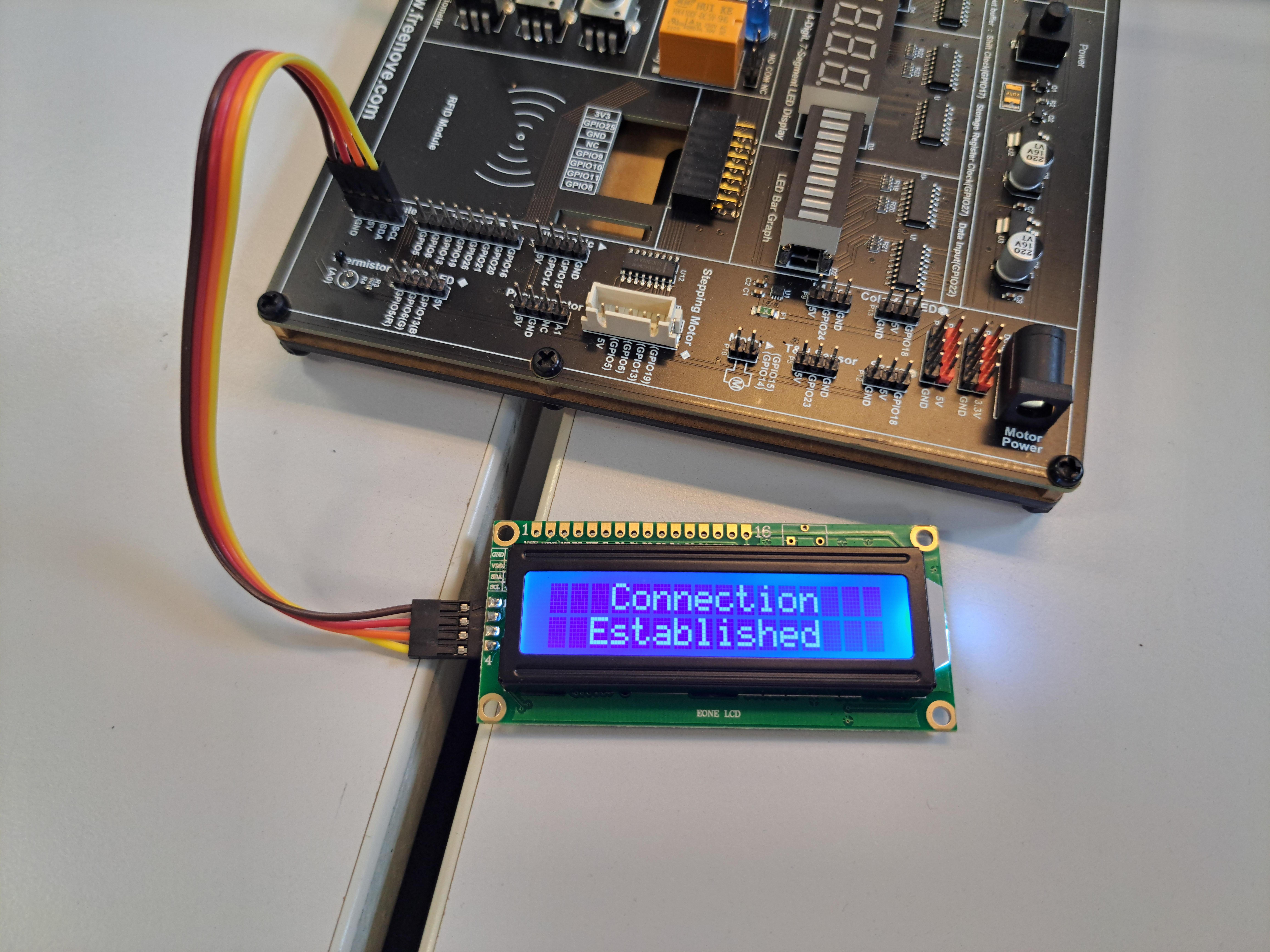
Our AI model is working fine on our personal computer, now we just need to pass this data to the Raspberry Pi to display it on the LCD.
The first thing to do is to have a Raspberry Pi with the right image installed on it (Linux-based raspbian).
You can find the imaging tool here. Download the right version for your operating system and run the imaging tool to install the operating system image for the Raspberry Pi on a micro-SD card. Once the installation is complete you can install the SD card into the Raspberry Pi and boot it up for the first time. When you are able to boot to the Raspberry Pi desktop you can set a static-IP to connect via LAN (SSH and socket connection) to the Raspberry Pi. A tutorial for setting a static IP can be found here. You need an IP on the same network as your personal computer, so I recommend using 192.168.168.x with x being any number you choose between 1 and 254(remember this IP!).
Once you have a static IP on the Raspberry Pi, you need to also set a static IP on your personal computer. On Windows this is fairly easily done in the ethernet settings menu by changing the IP assignment to manual and changing the IPv4 address to 192.168.168.y with y being a different number than x between 1 and 254.
If this is set up we can initialize communication between your PC and the RPI through an ethernet cable connection between the two. To open this connection we can use the Remote - SSH extension in Visual Studio Code, which you can install from the extension tab.
Now when you open a new remote connection you should be able to connect to 192.168.168.x using your set username and password on the RPI.
This step is complete once you can successfully enter the files on the Raspberry Pi and start adding programming files in its directory from your PC in Visual Studio Code.
Socket Communication to RPI and Display
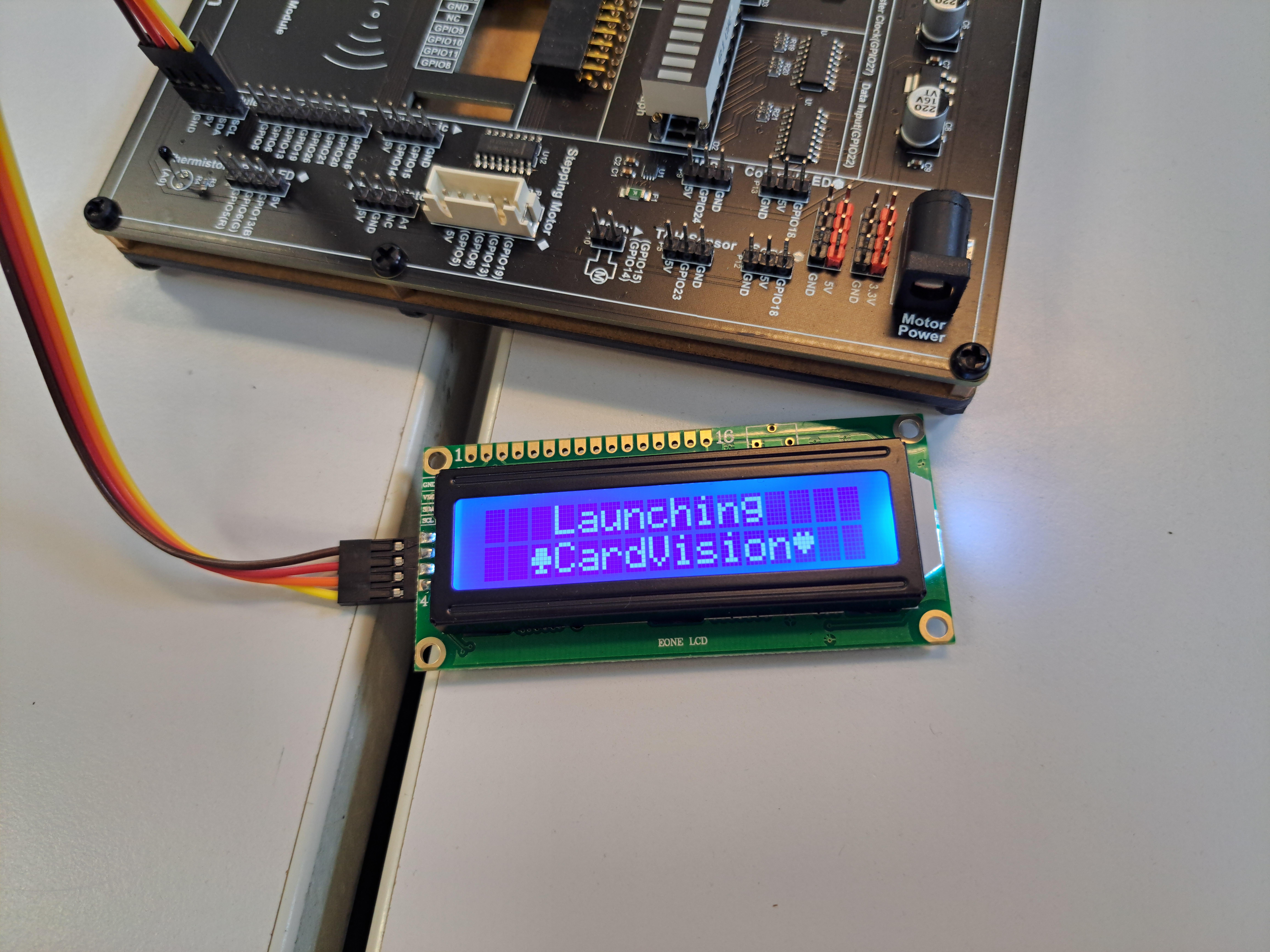
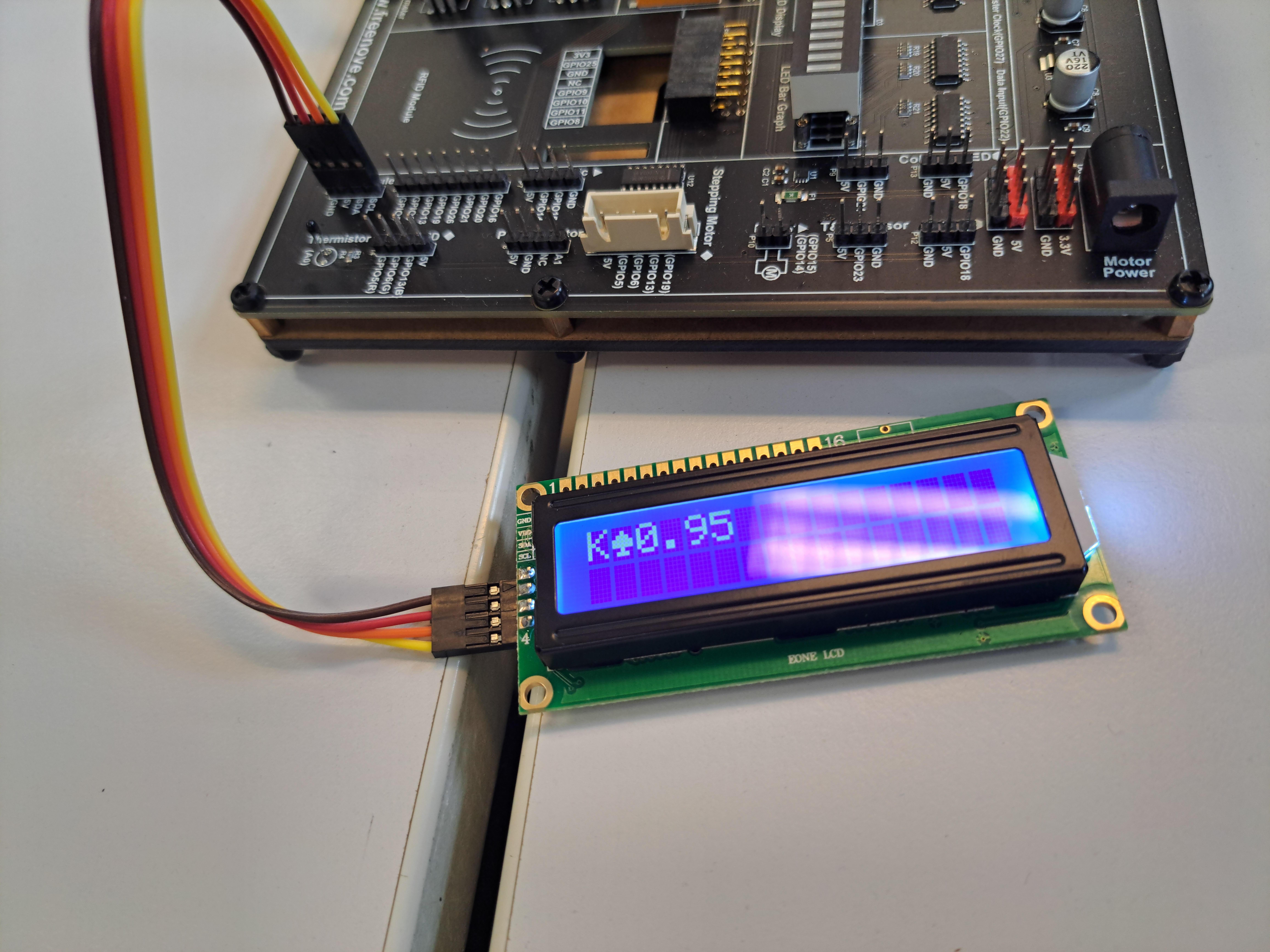
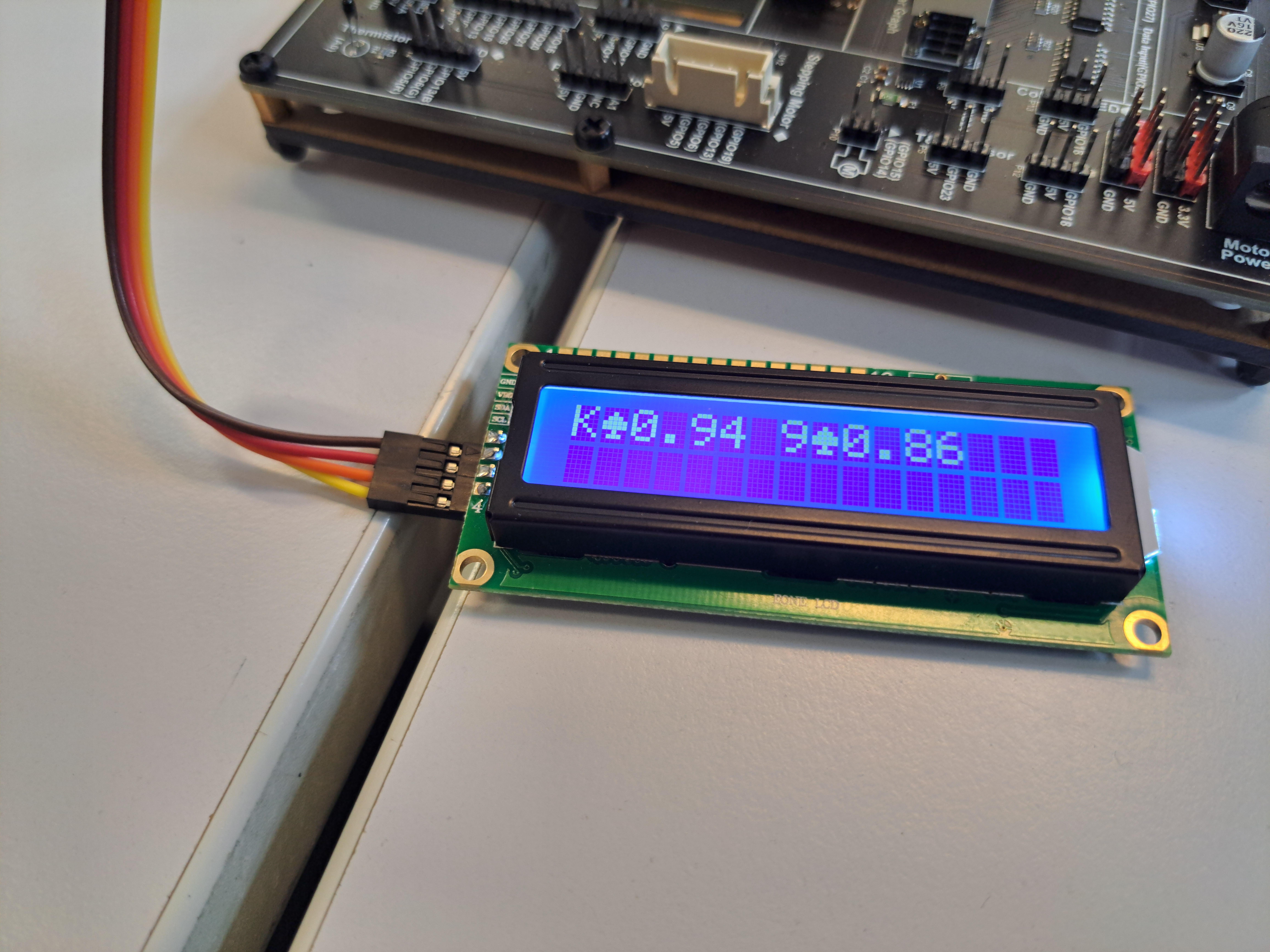
Now that we have a communication between the PC and the RPI we can add code to start a socket connection between the two to send data encoded over ethernet from the AI model to display on our LCD screen.
Using a dictionary in python we can save the prediction values from the model and the JSON library allows us to stringify and parse this data respectively before and after encoding for transmission.
# Added to PC code
import json
output = json.dumps(dictionary_detections)
socket.sendall(output.encode())

# Added to RPI code
import json
input = json.loads(received_data.decode())
dictionary_detections = json.loads(input)
Now we have a way to convert our data for transmission to the Raspberry Pi and convert it back into its usable form for python.
To enable this communication we need a socket connection set up between a client and server. In my case I use the RPI as the server and the PC as the client. An official guide for this method can be found here. Remember to use the static IP you set up in step 5 to connect the sockets.
When you can send and receive the data over the socket connection we just need to connect the LCD to the Freenove kit pins and connect the Freenove kit to the GPIO pins of the RPI and add code to display the received data on the LCD.
The code for the Freenove kit can be found in the tutorial pdf of the Freenove projects Github page, the part on the LCD starts on page 254 and includes images to guide you with the wiring and a code example for python starts at page 263. Don't forget to enable I2C communication on the RPI in the settings page.
Making the Case and Setting Up
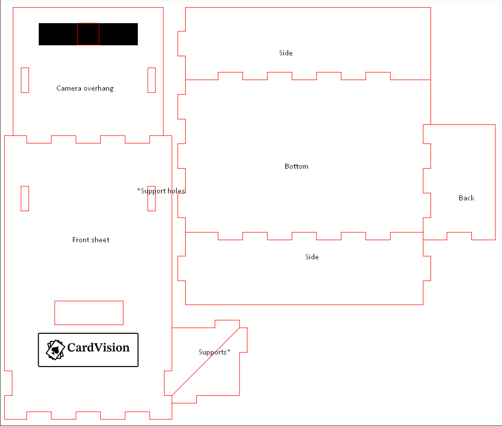
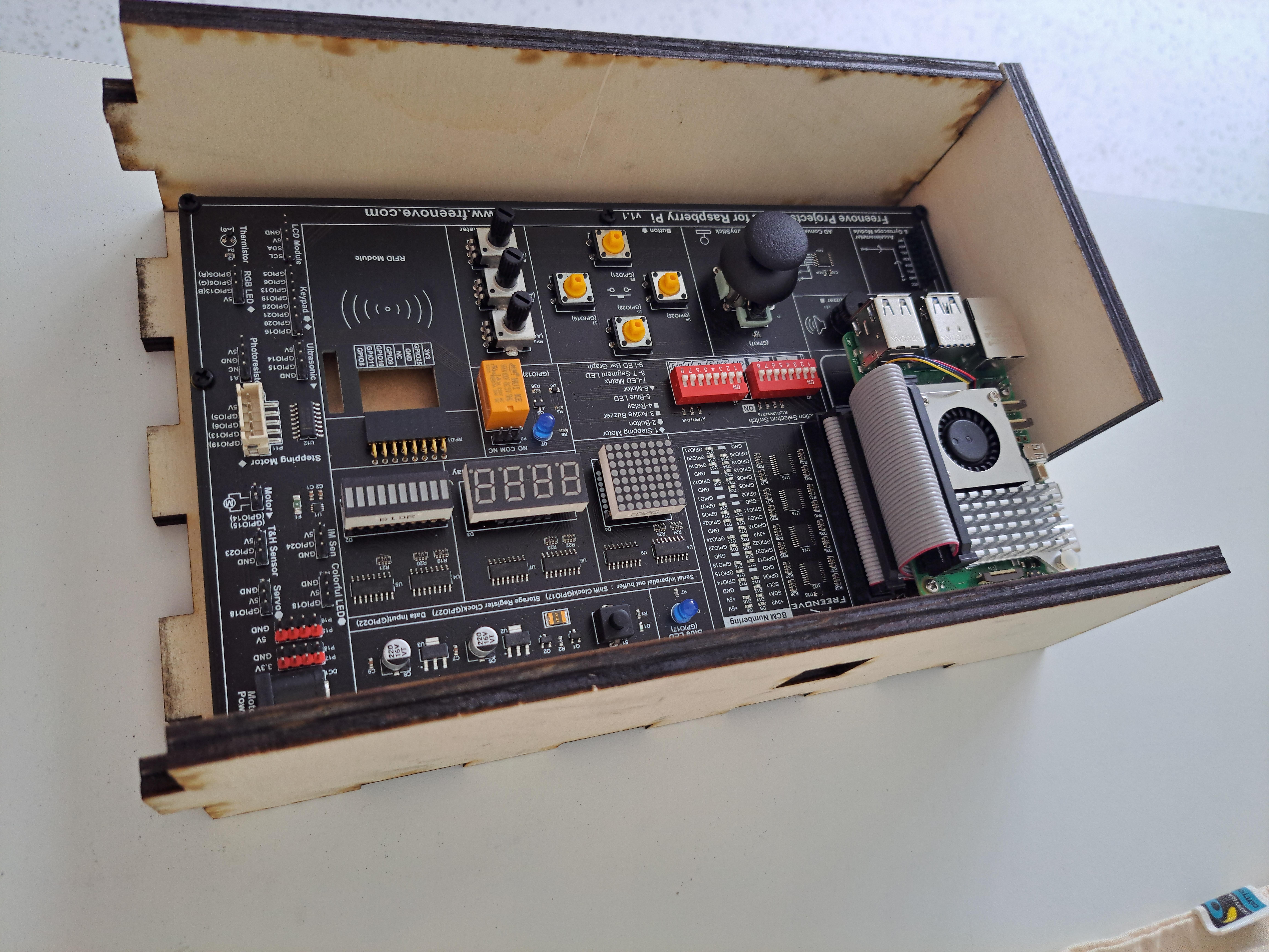
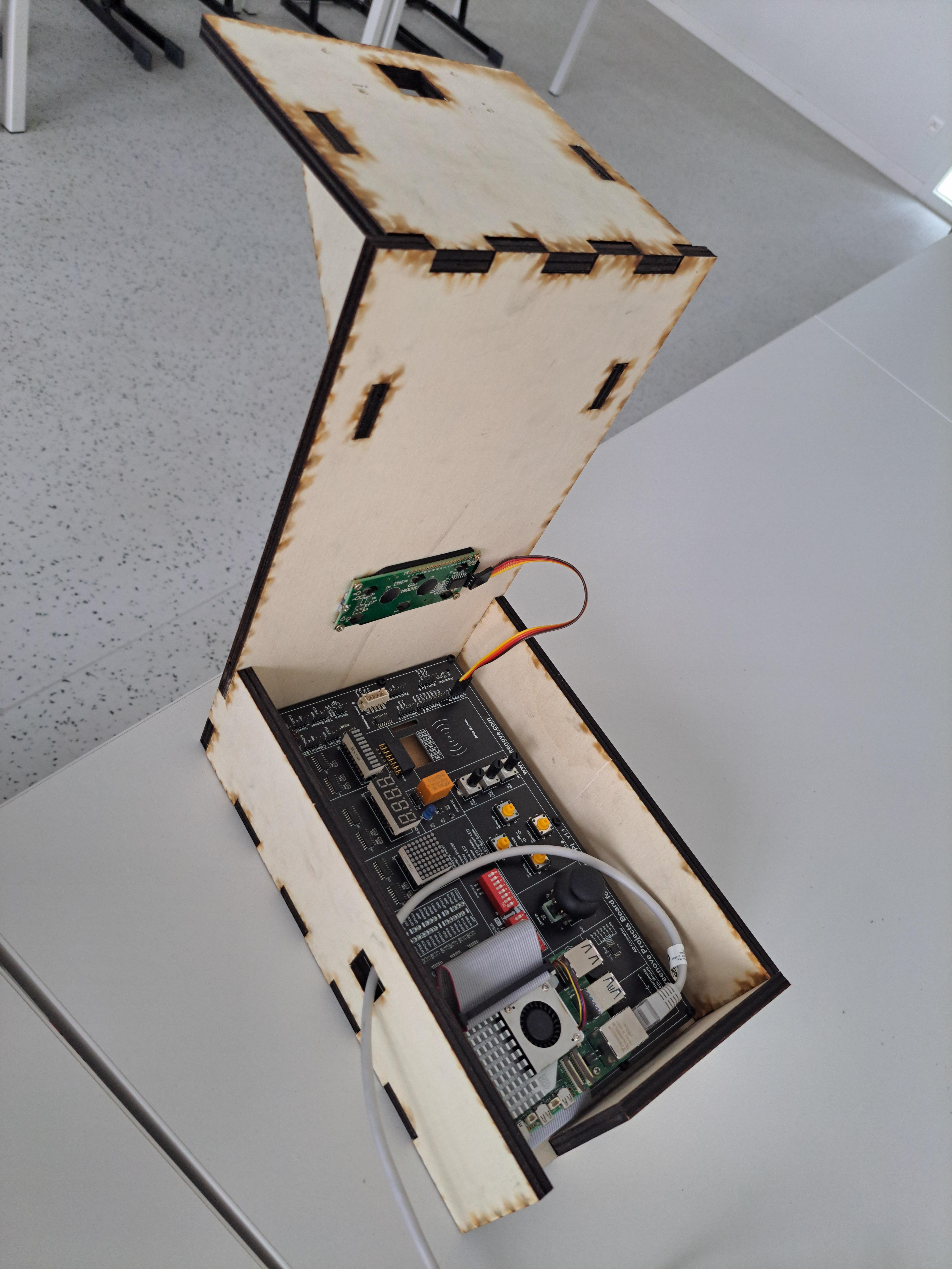
Now that our code is all complete and we can detect the cards and send the data to our Raspberry Pi and display it on the LCD screen we just need a case to tie it all together and make it look presentable.
I chose for a box design with a longer front sheet and an overhang to hold the camera and LCD cut out of plywood.
For the design you can begin with a basic box with finger joints from makercase. Simply enter the measurements on the page of your Freenove Kit which will have to fit nicely into the box. Remember to leave a small margin around the edges and to calculate in the width of the plywood in the dimensions. The inner dimensions should be a little larger than the dimensions of the Freenove kit with the Raspberry Pi installed. If you are using a lasercutter remember to use the right colors and line width for your lasercutter. (ask about it if you are using someone else's or look it up!)
You can alter the output svg in Adobe illustrator to add a little extra like engravings, a logo or cable routing holes.
If you don't want the hassle of plywood or figuring out where and how to use a lasercutter you can always create the design in tough cardboard. If you do make the case with plywood, make sure it's structurally sound (you can take inspiration from my attached design image) and glued together using some sort of wood or diy glue. For the LCD I used 3mm wood screws to screw it into the back of the plywood with a stress reducing material in between such as rubber or plastic. The camera is attached on top with zip-ties to keep it in place.
With the case all shaped and put together we can add in our kit and raspberry pi inside and connect everything up.
Start by running the socket server code on the raspberry pi, then you can start the AI detection model with the socket client code on your laptop and when everything's up and running correctly you can put cards on the table in view of the camera. The laptop will show live detection of the cards and send it to the Raspberry Pi, which will display it on the LCD display in the front.