Capture the Box
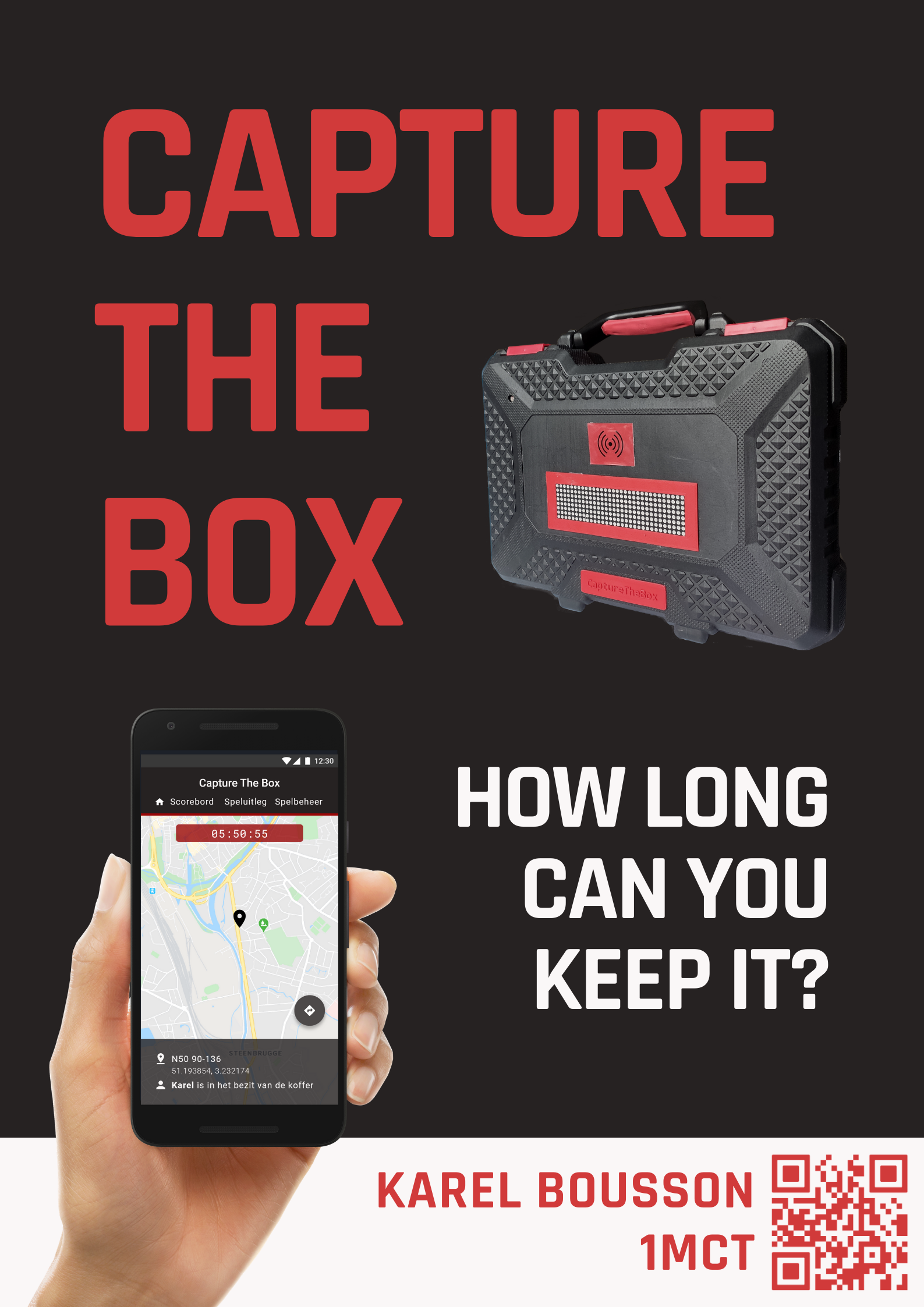
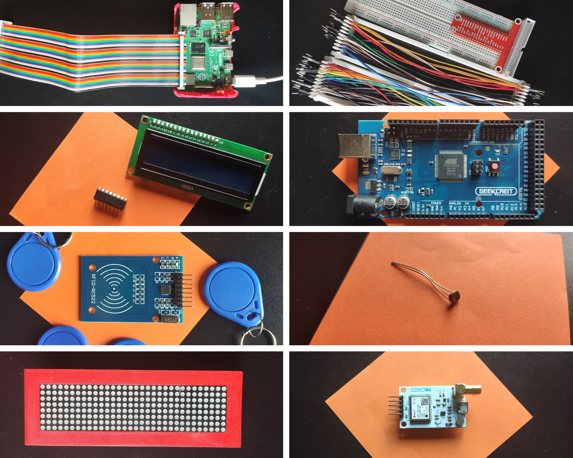
Capture The Box is a teambuilding game you can play with friends in your neighbourhood.
The goal is to capture the box and keep it in your possession for as long as possible whilst other players try to go and sneak it away from your porch or front garden.
This game uses GPS to locate the box and RFID tags to identify the players. An optional LDR can be added to match the intensity of the dot matrix display with the percentage of light in the area.
Downloads
Supplies
Microcontrollers and computers
- Raspberry Pi
- Arduino (Mega)
I chose an Arduino Mega over a normal Uno, because it has a lot more pins. This is necessary because we're using a Dragino LoRa shield, which would leave us with too little digital pins when using an UNO.
TIP: It's best to use a genuine one, because the Chinese clones don't always work as expected.
Sensors and modules
- 4 MAX7219 Dot Matrix Modules
Connect DOUT to DIN, CS to CS, CLK to CLK... - Light Dependent Resistor (10K) + Resistor (10K)
- NEO-7M (or similar) GPS Module
I'm using the VMA430 from Velleman - RC522 RFID Module
+ some RFID badges/cards
For using LoRa (wireless technology)
- Dragino Lora Shield
Optional sensors and modules
- An LCD display
To display the IP address of the Raspberry Pi
For making a test setup
- A breadboard and Dupont Cables (Male-Male
Optional (casing)
- Soldering iron
- An old tool case
- Materials for 3D printing
- Some thin wooden planks
- Some bolts and nuts (that can fit in Arduino holes).
My screws have a diameter of around 3mm.
An estimated price can be found in the BOM (Bill of Materials), included below.
Setting Up the Raspberry Pi
The Raspberry Pi is the heart of the Project.
It will run the frontend, backend and database. It will also be responsible for communication between the backend and the Arduino.
In order for us to use the Raspberry Pi, we will need to do the following:
Part 1: Install Raspbian on a Raspberry Pi
A tutorial on how to do that can be found here:
https://thepi.io/how-to-install-raspbian-on-the-ra...
Part 2: Install Raspbian on a Raspberry Pi
Setting up your home WiFi.
This can be done using
wpa_passphrase "YourNetwork" "YourSSID" >> /etc/wpa_supplicant/wpa_supplicant.conf
Reboot the Pi and you should see an IP address when typing in ifconfig
Part 3: Install the webserver and database
Once you have your Pi up and running, it's best to change your password.
This can be done with the command passwd.
Once that's done, go ahead and install Apache, PHP, MariaDB and PHPMyAdmin.
Apache, PHP
sudo apt install apache2 -y
sudo apt install php libapache2-mod-php -y
MariaDB
sudo apt install mariadb-server mariadb-client -y
sudo apt install php-mysql -y
sudo systemctl restart apache2.service
PHPMyAdmin
sudo apt install phpmyadmin -y
Don't forget to set a secure MySQL password.
Part 4: Installing the necessary Python libraries
For the backend, we will need some libraries. These can be installed using the pip3 command.
pip3 install mysql-connector-python
pip3 install flask-socketio
pip3 install flask-cors
pip3 install gevent
pip3 install gevent-websocket
pip3 install ttn
Laying Out the Electronics
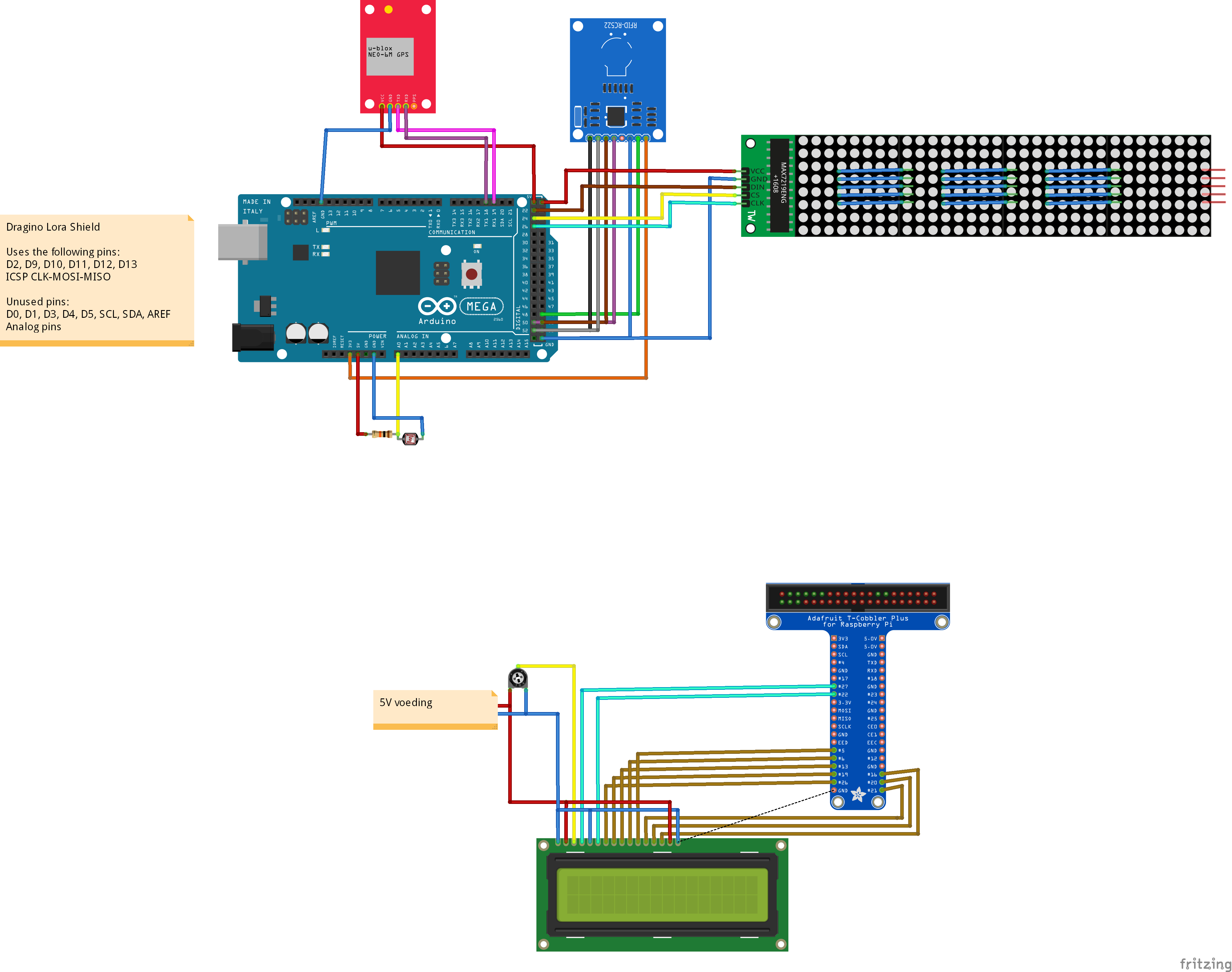
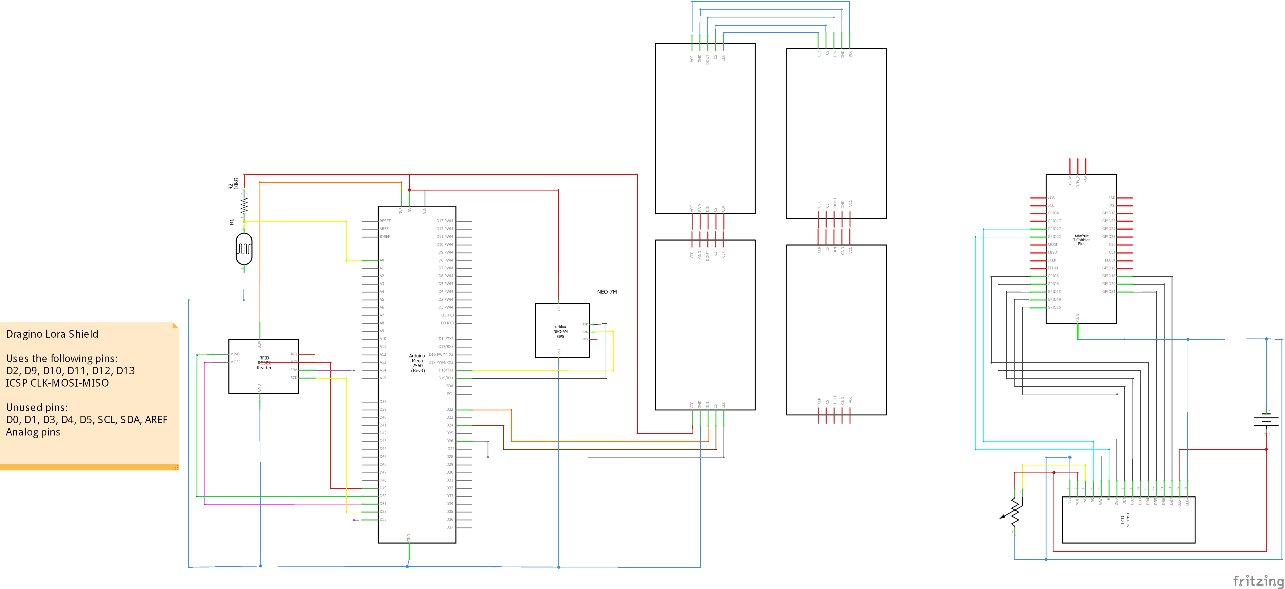
To make this Project work, we need to connect all the electronics.
The LoRa shield can be easily put into place. Just align the pins with the pins on your Arduino.
The other connections are described in my Fritzing scheme. Which can be downloaded here:
Downloads
Designing the Database
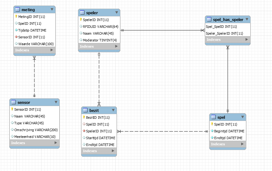
To be able to store all the game and sensors data, I made a few tables:
meting and sensor
The measurements from the sensors, found in the sensor tables.
It contains a reference to the sensor, the value of the measurement (e.g. coördinates: 51.123456; 3.123456) and an optional game id (if a game was active during the measurement).
speler
The player names and the UID of their RFID badge. An optional field moderator is added, this person can modify the game (e.g. stopping it before time).
spel
The game info (start and endtime).
spel_has_speler
The relation between spel and speler. This is where players are assigned to a game.
bezit
In this table, the score is saved. It contains the game id, player id, the time he stole the box and the time he lost it (when someone else steals it or when the game ends). By subtracting the begin time from the end time, you can calculate the score he got from that capture.
An export of the database can be found on my GitHub (https://github.com/BoussonKarel/CaptureTheBox)
Open the sql in PHPMyAdmin / MySQL Workbench and run it. The database should now be imported.
Setting Up an Account on TTN
Step 1: Sign up for an account on TTN and create an application.
Sign up for an account on TheThingsNetwork, then go to Console > Add application.
Pick a name for your application and click Add application.
Step 2: Register a device
When you've made your application, go to Register device.
Pick a device id, this can be whatever you want (as long as it's snake case) and click Register.
Click on the Generate icon under Device EUI, so TTN wil generate one for you.
Step 3: Writing down your credentials
Now go to your Device and click on the Code icon next to Device EUI, App EUI and App key. It should now appear as an array of bytes.
Before you copy, click the Switch button and make sure your Dev EUI and App EUI are LSB FIRST.
Your App Key should stay MSB FIRST (don't change that).
You'll need these keys in the next step: Setting up the Arduino.
Step 4: Writing down your Application Acces key
Now we'll need one more key to set up MQTT on our Raspberry Pi.
Go to your Application and scroll down to Acces Keys.
You'll need this in the Backend step.
Setting Up the Arduino
Arduino code can also be found on my GitHub, under Arduino
(https://github.com/BoussonKarel/CaptureTheBox)
This code is split into multiple tabs, to keep it organised.
main.ino
The main code: pin declarations, setup() and loop()
0_LoRa.ino
This code handles the communication using LoRa.
It puts the data of the LDR, GPS and RFID tags in an array of 13 bytes and sends this over to TheThingsNetwork.
1_LDR.ino
Using analogRead(), it measures the amount of voltage over the Light Dependent Resistor.
This is then converted to a percentage of light (0 being nothing, 100 being a cellphone flashlight).
2_GPS.ino
This uses Serial communication using TX1 and RX1 (Serial1).
It uses NMEA messages (the $GPRMC messages to be precise) to find the latitude and longitude of the box.
3_RFID.ino
Using the MFRC522 library, this code scans for new RFID tags.
Whenever one is present, it stores in as RFID_lastUID.
4_DotMatrix.ino
This code is used initialize and set the dot matrix display.
It contains definitions for the loading animation etc...
Setting it up.
Before you can upload this code to your Arduino, you'll need to install a few libraries.
The Arduino-LMIC library by matthijskooijman (https://github.com/matthijskooijman/arduino-lmic)
The MFRC522 library for the RFID reader (https://github.com/miguelbalboa/rfid)
Now, go to main.ino and change the DEVEUI, APPEUI and APPKEY to the ones you copied last step.
Setting Up the Backend
The backend for this Project can be found on my GitHub, under RPI > Backend
(https://github.com/BoussonKarel/CaptureTheBox).
How does it work?
- Every 10 seconds, the code looks for an active game.
If one is found, it is saved in a variable called huidigSpel (currentGame) - If the mode is set to Serial, a cable is used between the Arduino and the Pi.
The Pi polls for the values of the LDR and GPS. The Arduino responds with a JSON format.
RFID tags are sent whenever they are presented.
This mode was solely used for development purposes and is not really necessary anymore. - If the mode is set to LoRa, a MQTT client is created that triggers a callback whenever LoRa data is received by TTN. This contains LDR, GPS and RFID data.
- The frontend can retrieve data using the API endpoints. Most of the data is retrieved using huidigSpel.id.
Data is returned in JSON format using jsonify()
Modify the settings
Go to secrets.py and fill in the name of your LoRa application and your Acces Key (you wrote down earlier).
Go to config.py and fill in your Database credentials (such as password, user...)
Setting it up as a service
Try to run app.py, once you have confirmed this is working, we can use it as a service.
This will automatically start the code in the background when you boot up your pi.
To do this copy ctb_service.service to /etc/systemd/system/ctb_service.service.
sudo cp ctb_service.service /etc/systemd/system/ctb_service.service
Now enable it using systemctl enable ctb_service.service
If you need to make some changes to the code, you can easily stop it using systemctl stop (this will start up again on reboot) or disable is (stop it from automatically starting up) using systemctl disable.
If you need to consult the logs (because of errors), you can use journalctl -u ctb_service.service.
More info on services can be found here: https://www.raspberrypi.org/documentation/linux/us..
Setting Up the Frontend
As usual, frontend can be found on my GitHub, under RPI > Frontend
(https://github.com/BoussonKarel/CaptureTheBox)
Paste this in the /var/html folder of your Raspberry Pi.
This contains all the necessary web pages for the game.
It also contains a script to communicate with the backend (both realtime and using the API endpoints).
Adding a Casing
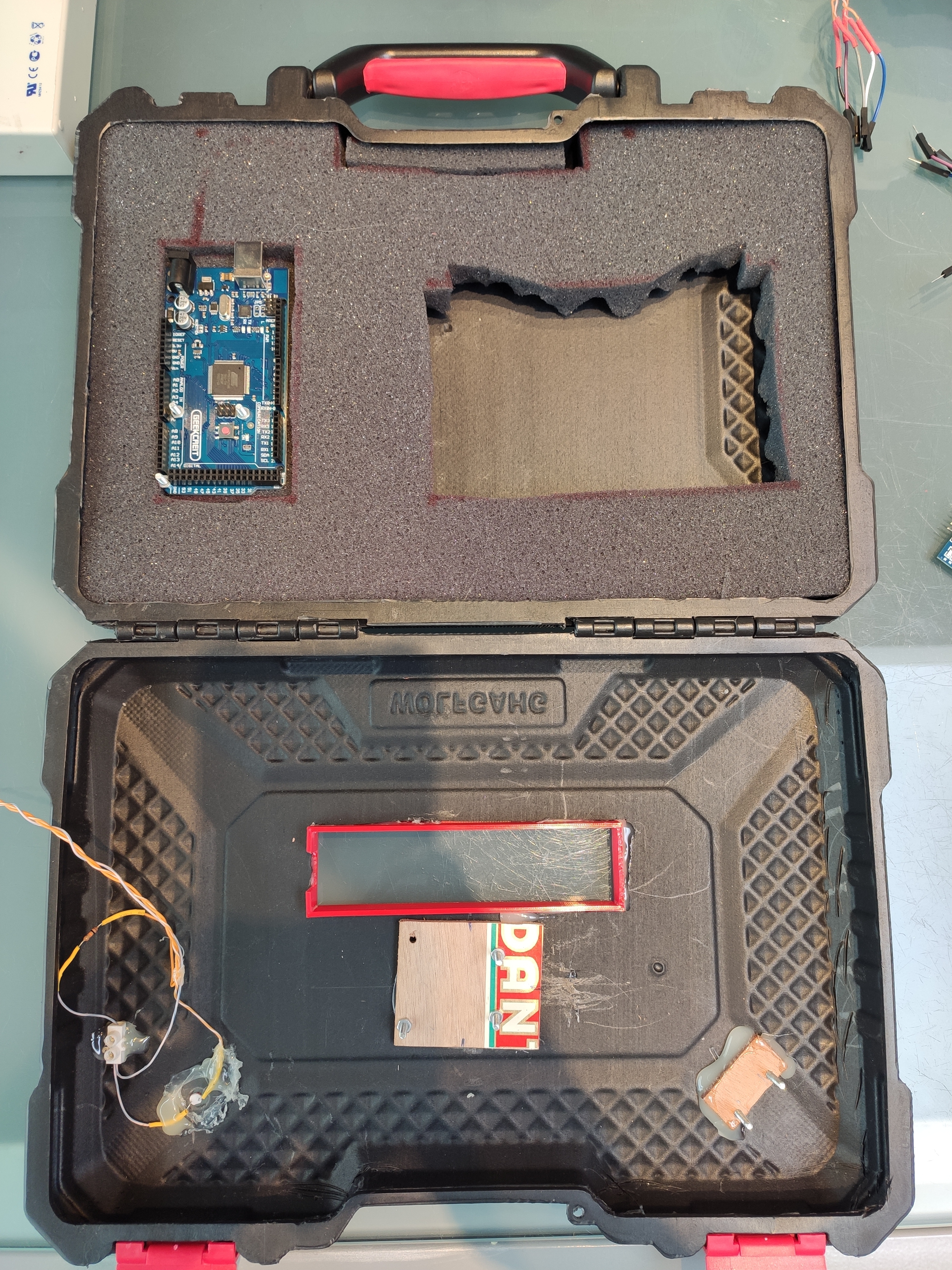
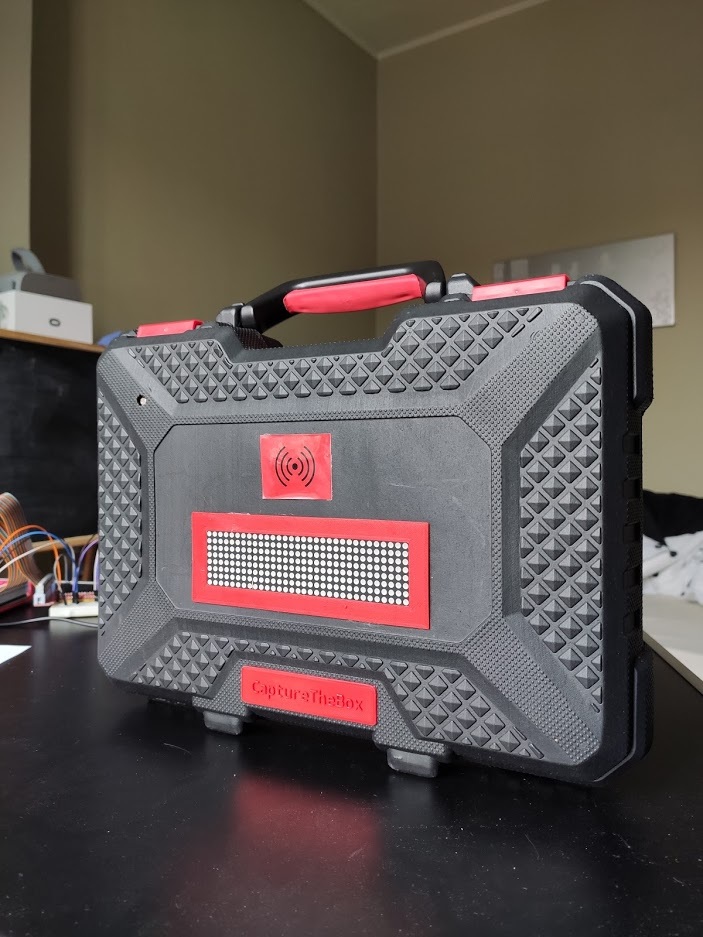
For the case, I used an old tool case, together with the following materials/techniques:
- 3D printing
- Foam for keeping the battery into place
- Recycled wooden planks
- Hot glue
- Screws and nuts
What you do with your case is your choice! I'm going to give you artistic freedom.
For inspiration, I've added some photo's of my (finished) case.