Capacimeter With Arduino

A Capacimeter is an instrument used to measure the capacitance of a capacitor. In this tutorial, we will guide you step by step to build your own Capacimeter using an Arduino board, basic components, and some code.
Electronic components of the project
Arduino Nano

The Arduino Nano is a small, complete, and breadboard-compatible board based on the ATmega328 (Arduino Nano 3.x). It has more or less the same functionality as the Arduino Duemilanove, but in a different package. It lacks only a DC power jack and works with a Mini-B USB cable instead of a standard one.
MicrocontrollerATmega328 ArchitectureAVR Operating Voltage5 V Flash Memory32 KB of which 2 KB used by bootloader SRAM2 KB Clock Speed16 MHz Analog IN Pins8 EEPROM1 KB DC Current per I/O Pin40 mA (I/O Pins) Input Voltage7-12 V Digital I/O Pins22 (6 of which are PWM) PWM Output6 Power Consumption19 mA PCB Size18 x 45 mm Weight7 g
Pin Diagram

An Arduino Socket
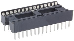
Female Pins

Dupont Female to Male Cables

OLED Display SH1106
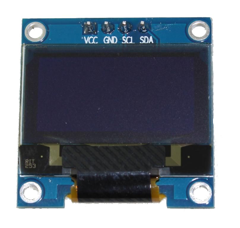
This is a 128x64 dot monochrome OLED display module with I2C interface. It has several advantages compared to LCD displays, including high brightness, very good contrast, a wider viewing angle, and low power consumption. It is compatible with Arduino, Raspberry Pi, and PIC microcontrollers among others. It works with logic levels from 3.3V to 5V, has a viewing angle greater than 160 degrees, and a screen size of 1.3 inches. It is powered by a voltage of 3.3V to 5V and can be used in applications such as smartwatches, MP3 players, thermometers, instruments, and various projects, etc.
Features
- Interface: I2C(3.3V / 5V logic level)
- Resolution: 128 x 64
- Angle of view: >160 degrees
- Display color: Blue
- Display size: 1.3 inch
- Driver IC: SH1106
- Power supply: DC 3.3V~5V
- Operating temperature: -20~70°C
- Application: smart watch, MP3, thermometer, instruments, DIY projects, etc.
KY-004 Button Module

PCB


Electronic diagram of the PCB

Circuit

Source Code
#include <Capacitor.h>
#include <U8glib.h>
#define BUTTON_PIN 4  // Button pin
// Capacitor under test.
// Note that for electrolytic capacitors, the first pin (in this case D7)
// must be positive, and the second (in this case A2) negative.
Capacitor capacitor(7, A2);
// Configure the SH1106 OLED display
U8GLIB_SH1106_128X64 oled(U8G_I2C_OPT_NONE);
void setup() {
  Serial.begin(9600);
  oled.setFont(u8g_font_6x10);  // Set the font for the OLED display
  pinMode(BUTTON_PIN, INPUT_PULLUP);  // Set the button pin as input with pull-up resistor
  // Show initial message on the OLED display
  oled.firstPage();
  do {
    oled.drawStr(0, 20, "Press the button");
    oled.drawStr(0, 40, "to read the capacitor");
  } while (oled.nextPage());
}
void loop() {
  if (digitalRead(BUTTON_PIN) == LOW) {  // If the button is pressed
    float capacitance = capacitor.Measure();  // Measure capacitance (in pF)
    // Convert capacitance to nF and uF
    float capacitance_nF = capacitance / 1000.0;
    float capacitance_uF = capacitance / 1000000.0;
    // Print to Serial Monitor
    Serial.print("Capacitance: ");
    Serial.print(capacitance);
    Serial.print(" pF, ");
    Serial.print(capacitance_nF, 3);
    Serial.print(" nF, ");
    Serial.print(capacitance_uF, 6);
    Serial.println(" uF");
    // Draw on the OLED display
    oled.firstPage();
    do {
      oled.drawStr(0, 10, "Capacitance:");
      // Show in pF
      oled.setPrintPos(0, 30);  // Text position
      oled.print(capacitance);
      oled.print(" pF");
      // Show in nF
      oled.setPrintPos(0, 45);  // Text position
      oled.print(capacitance_nF, 3);
      oled.print(" nF");
      // Show in uF
      oled.setPrintPos(0, 60);  // Text position
      oled.print(capacitance_uF, 6);
      oled.print(" uF");
    } while (oled.nextPage());
    delay(1000);  // Wait 1 second before allowing another reading
  }
}
