Campus Connections
Problem Statement
The end of the semester is often a stressful time of year for the students of Indiana University as they worry over final exams and grades. Indiana University already offers some stress relieving strategies such as Balance at Kelley and Jump into Finals at the SRSC. However, those do not focus on student connectivity. The goal of Campus Connections is to help students spread messages of encouragement and positivity to their peers, reminding students that they are not alone and reduce stress.
System Overview
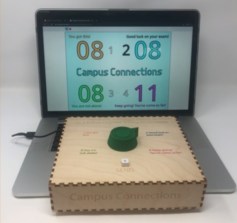
The primary function of Campus Connections is to log and display how many times each of the four given positive messages has been sent. To use Campus Connections, choose one of the four messages on the box and turn the dial to the chosen one. Press the “send” button to lock message--this will add 1 to the corresponding message tally on the display. The background color of the display will also change in correspondence to the color of the messages, signifying the message that was last sent. The Hope Board is our control and adds a physical component that users can interact with along with the code.
Supplies
Campus Connections
- Plywood (⅛” thickness) (25” x 16”) 1x Adafruit Playground Express -- https://www.adafruit.com/product/3333
- 1x Potentiometer -- https://www.adafruit.com/product/4133
- 1x Tactile switch button -- https://www.adafruit.com/product/4133
- 1x USB Standard to USB Micro cable -- https://www.adafruit.com/product/4133
- 5x Alligator clip wire -- https://www.adafruit.com/product/4133
- 3x Short solid-core wire (~3 in. each) -- https://www.adafruit.com/product/4133
- Solder/soldering iron
- Laptop with USB Standard port (to run code and use as a display)
- Wood glue
- Hot glue gun
- Laser cutter
- 3D Printer
Hope Board
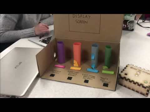
- Poster Board
- Markers
- 4 different-colored stacks of sticky notes
Cut the Box
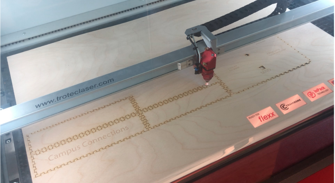
- Download and laser cut the CC_Box.ai file from the Github repository (https://github.com/GavinWhelan/Campus-Connections.git).
- Be sure to use ⅛ inch plywood and watch the laser cutter during the duration of the cut. Make sure to follow all safety protocols and have a University teaching assistant help if necessary.
Construct the Box
Using wood glue, connect each piece, one by one, at the hinges. (This is much easier with two people.) The wood glue will hold the pieces together instantly, but will likely need several hours to dry fully. Remember not to glue the lid (the large, square piece with text on it) to the base, as you will need to be able to open the box to access the electronics.
Print Dial, Button Cover, and Button Seat
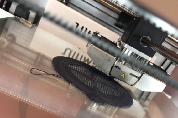
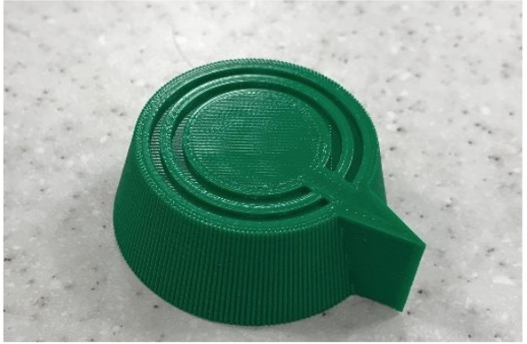
- Download the dial (CC_Dial.stl)
- Download the button cover (CC_ButtonCover.stl)
- Download the button seat (CC_ButtonSeat.stl) from the Github (https://github.com/GavinWhelan/Campus-Connections.git)
- Use a 3D printer to print the components. The dial should be roughly 2” in diameter
Assembly A: Attach the Button Switch to the Box Lid
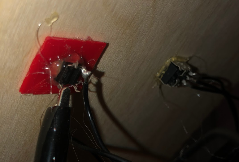
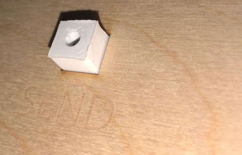
- Use your glue gun to hot-glue the button seat to the base of the button switch, with the button shaft through the hole in the button seat. (Be careful not to glue the button shaft to the button seat!)
- Hot-glue the button shaft into the hole in the button cover. The shaft will not thread entirely through the hole in the button, and there should be some space between the button cover and the button seat.
- Hot-glue the button seat to the inside of the wood-cut box, so that the button cover sits inside the square hole in the top of the box.
Assembly B: Attach the Potentiometer to the Box Lid
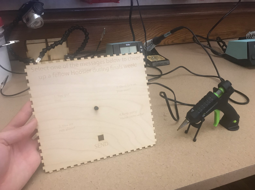
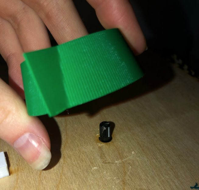
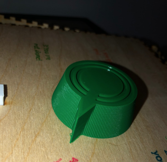
- Hot-glue the potentiometer to the inside of the box, so that the shaft sticks through the small circular hole on the top of the box. (Again, be careful not to glue the shaft to the base!)
- Hot-glue the dial to the potentiometer shaft on the exterior of the box, making sure that the arrow on the dial aligns with the white marker on the potentiometer knob.
Assembly C: Connect the Wiring
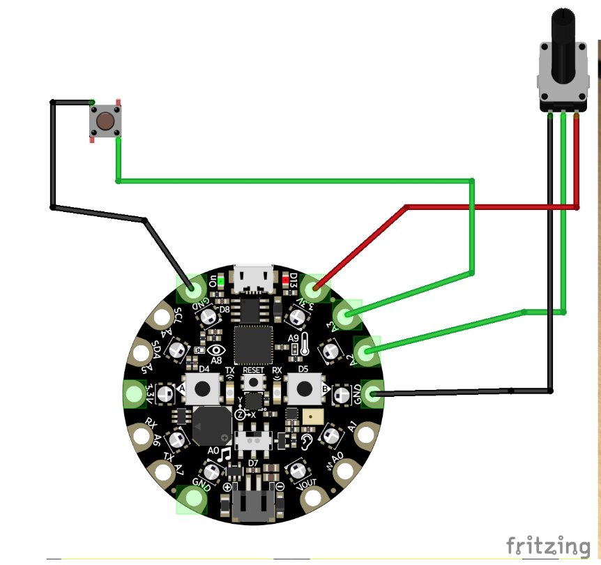
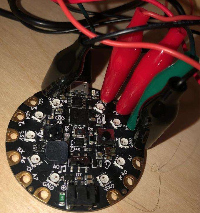
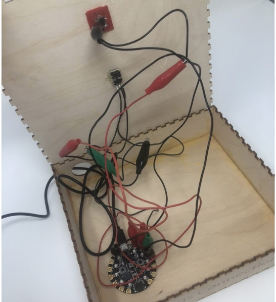
- Solder a short length of wire onto each of the three potentiometer leads--this will make it easier to connect the alligator clips to the potentiometer.
- Using alligator clips, connect the potentiometer and button to the Playground as shown in the Fritzing diagram below:
- Thread your USB Standard-to-Micro cable through the large hole in the back of the box, and use it to connect your Playground to your computer.
Download Code and Run Program
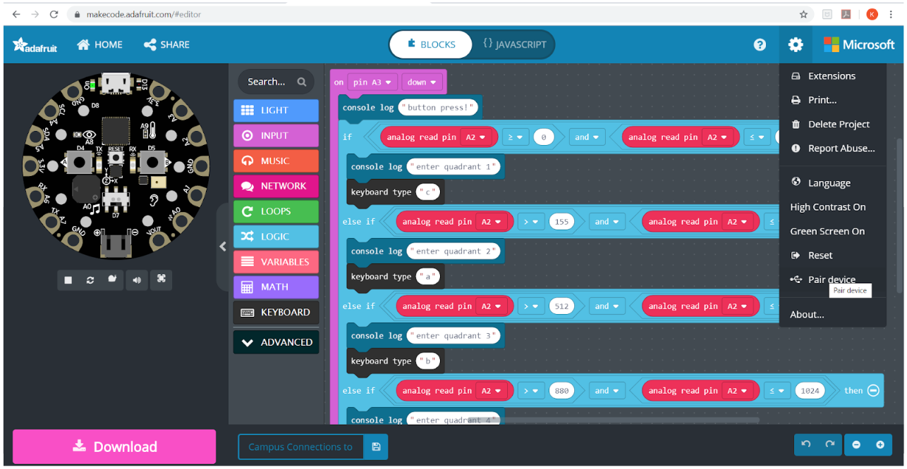
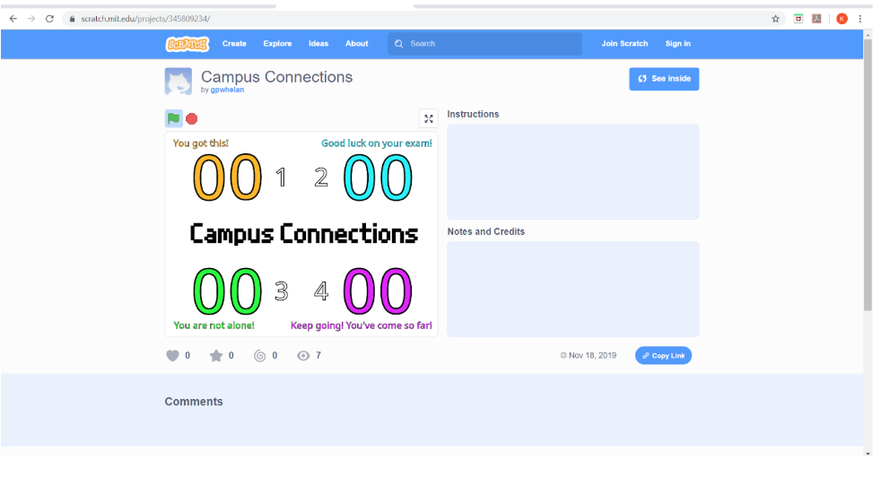
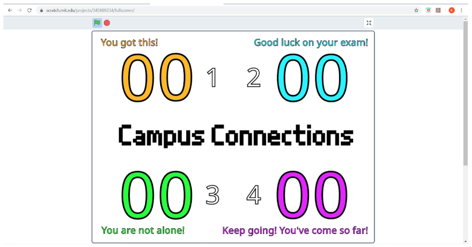
NOTE: Use Google Chrome for code to work properly
In order to properly run Campus Connections and the display, you must have Scratch and MakeCode running on your computer; the easiest way to do this is to follow the provided links (see “Links to Code” above).
- First, open the MakeCode link. In the top right corner of the Makecode page, pressing the “more” button gives you the option to pair your device.
- (This program tells the Playground to send a certain keyboard button press (depending on the direction of the dial) to your computer when the send button is pressed)
- Press the “reset” button on your Playground (the small one at the very center), then download the program with the pink “Download” button in the bottom left-hand corner of the page.
- To test that your Playground is properly connected, press the “Send” button--if it logs a value to the MakeCode console (above the “download” button, a button called “Show console Device” will appear), your code is working!
- Fit the lid with the electronics onto the box base. (Do not glue! You may need to reset the Playground every time you plug it into your computer.)
- Now open the Scratch program and click the green flag.
- For an improved display experience, expand the display window to fullscreen.
- (This program takes button press inputs from the Playground and uses them to update the tally of the corresponding message)
Your Campus Connections unit is ready to use!
Construct the Hope Board
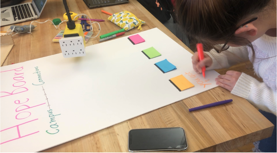
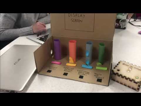
- Write “Hope Board” in large letters across the top of the poster, positioned vertically.
- Hot glue the bottom of the stacks of sticky notes along the bottom leaving enough room to write the messages underneath.
- In corresponding marker colors, write one of the following messages below each sticky note stack:
- You got this!
- Good luck on your exam!
- You’re not alone!
- You’ve come so far!