CYBER.PY Zero-Three


Greetings everyone, and welcome back.
This is CYBER.PY Zero-Three, a Cyberdesk-themed Raspberry Pi PC that is equipped with the Waveshare 7.9-inch ultra-wide HDMI display.
This is basically another installment of my previous Cyber.PY projects, which you can see by visiting the links below.
https://www.instructables.com/CyberPY-Zero-One/
https://www.instructables.com/Cyber-PY-Zero-Two/
First, the whole design was modeled in Fusion360. Then it was 3D printed with an Ender 3 printer in a two-color scheme.
The Raspberry Pi 4 serves as the project's brain, but it can be swapped with a Raspberry Pi 5 or even a lower version because all of the fittings are interchangeable and compatible with all Pi models.
In this configuration, Raspbian has been loaded on the Raspberry Pi, and it may be utilized for numerous applications. For example, I plan to give my younger brother access to this setup so he can learn Python programming through Thonny.
This configuration is powerful and capable of running everything we throw at it thanks to the Pi4; for instance, Minecraft Pi Edition Modded is running on this setup.
Installing Pi-apps will allow you to add a ton of programs to this setup, such as games like DOOM and emulators like PPSSPP. We even personalized our Pi to look like a Mac by using a custom Mac OS theme.
In order to expand the Pi4's IO ports, we have also added a USB hub to this device.
Additionally, the display we're using is a touch screen.
This Instructables is about the whole build process of this project, so let's get started with the build.
Supplies
These were the materials required for this build:
- Raspberry Pi 4
- Waveshare 7.9-inch Display (Provided by PCBWAY)
- 3D-printed body
- DC-DC 5V/3A Modules
- DC Barrel Jack
- M3 Standoffs
- M3 Bolts
3D Design


In order to model the 7.9-inch display, we first had to build the body of the model. To do this, we measured the display manually and created the model.
Then, as the display has PCB standoffs placed on it, especially for mounting the Raspberry Pi, the Raspberry Pi 4 model was imported into the design and placed on the back of the display.
The whole model was then designed around the screen.
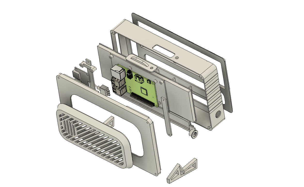
The design was divided into two main parts: the main body and the back lid.
The main body holds the screen and Pi arrangement from the inside; The exterior features a curved screen front cover part that we made after the front appearances of vintage CRT monitors;
We modeled the front face by taking influence from CRT monitors, which shared similar designs. To enable us to print the main body and the front face using various colors of filament, we separated the two pieces. This will provide contrast to the model and improve its aesthetic appeal.
To enhance the visual appeal, we modeled a second part for the main body and created an opening that is filled with an orange-printed part. We named the following component the slot part.
I have combined two distinct pieces with two color tones across the model to create a single assembly, to enhance the visual appeal and design of the project.
The base lid part is modeled with a large opening in the middle. In this opening, we will add a grill for air ventilation, This grill part is printed from transparent PLA, and the lid itself is printed with orange PLA.
We have modeled two screen holders inside the main body that, when installed, will hold the screen and Pi assembly in place.
We also added a USB hub, which is installed on the left side of the model, since we could not access the USB ports on the Raspberry Pi because it was mounted in the middle.
On the right side, we have added a DC Barrel Jack connector for powering the Pi and the display.
There's also a switch added on the left side for turning power ON or OFF.
Once the model was finished, we took the entire design, rotated it by 13 degrees, and created a stand to support the entire model at a 13-degree tilt. We took this step since all of the old monitors had a slight tilt.
3D-printed Parts


Following the design's completion, we exported each component into a mesh file and used two filaments—transparent PLA and orange PLA—to 3D print every part.
- Main Body: Transparent PLA with a 1mm nozzle and 0.3mm layer height
- Front Cover: Orange PLA with a 0.6mm nozzle and 0.2mm layer height
- Back Lid: Orange PLA with a 1mm nozzle and 0.3mm layer height
- Back Lid Grill: Transparent PLA with a 0.6mm nozzle and 0.2mm layer height
- Screen Holder 1: Transparent PLA with a 0.6mm nozzle and 0.2mm layer height
- Screen Holder 2: Transparent PLA with a 0.6mm nozzle and 0.2mm layer height
- IO Cover: Orange PLA with a 0.6mm nozzle and 0.2mm layer height
- Slot Part: Orange PLA with a 0.6mm Nozzle and 0.2m layer height
We use the above settings to print each part with our Ender 3 printer.
7.9-inch HDMI LCD DISPLAY


The Ultra Wide 7.9-inch HDMI Display, made by Waveshare, is the main component of this project.
This screen is fantastic; it has a 400x1280 pixel resolution and is incredibly bright. By holding down the ON/OFF button for an extended period of time, you can adjust the screen's brightness.
This is a 5-point capacitive torch screen that has a 6H hardness tempered glass panel.
This screen requires a stable 5V/2A power source to run smoothly.
Setting Up the Display With Raspbian OS
With our Raspberry Pi, we are running Raspbian OS, and the simplest method for installing the OS is by far utilizing the Raspberry Pi imager software.
After making the boot drive into an SD card, we open the config.txt file of the Raspbian OS and add the below lines to it.
hdmi_group=2
hdmi_mode=87
hdmi_timings=400 0 100 10 140 1280 10 20 20 2 0 0 0 60 0 43000000 3
You should also include an extra line in order to set the proper display orientation, which in our instance is 270°.
display_rotate=3
Here, 3 means 270°, 2 will make the display rotate 180°, and 1 will make the display rotate 90°.
Additionally, we need to comment out dtoverlay=vc4-fkms-V3D in the config file
Waeshare has made a brief wiki about this process, about how this display can be used with a PC, and more, which you can checkout.
PCBWAY GIFTSHOP


As for sourcing this display, we got it from PCBWAY's Giftshop
PCBWAY Gift Shop is an online marketplace where you can get a variety of electronics modules and boards for their genuine price, or you could use the PCBWAY currency, which is called beans.
You get beans after ordering something from PCBWAY as reward points, or you can also get them by posting any project in the PCBWAY community.
Over the past ten years, PCBWay has distinguished itself by providing outstanding PCB manufacturing and assembly services, becoming a trusted partner for countless engineers and designers worldwide.
Their commitment to quality and customer satisfaction has been unwavering, leading to significant growth and expansion.
You guys can check out PCBWAY If you want great PCB service at an affordable rate.
Pi4 With 7.9-inch Display: Test Setup


We must test the display first, and we do this by first incorporating the Pi with the display before beginning the body assembly process.
- First, we attach the supplied M2.5 PCB standoffs to the mounting holes provided on the display.
- Next, we connect the output pins of a DC-DC Buck Module to the 5V and GND of the display. This DC-DC module outputs a constant 5V/3A, which is stepped down from a 12V adaptor.
With the help of a multimeter, we were able to identify the Micro USB's positive terminal, which was directly connected to the input terminal of the onboard AMS1117 voltage regulator.
- The Raspberry Pi is then positioned on the back of the display using the PCB standoffs, and it is fastened in place with four M2.5 bolts.
- Then, we added a second DC-DC Buck Module, which plugs into the Raspberry Pi 4 Type C Port via a USB Type C connector on its output.
The plan was to supply stable 5V/3A to the Pi and the display using two different DC-DC Buck modules.
- Finally, we attached the touch USB adaptor and the HDMI-to-micro HDMI port adaptor that came with the display set to connect the Pi and display together.
Raspbian OS


After installing Raspbian OS onto the SD card using the Raspberry P imager, we made the required modifications to the configuration file to enable display.
Everything was working smoothly after the desktop environment booted, and the computer did not lag.
Additionally, we used the Ethernet port to connect the device to the internet and browsed Chromium.
To use the OS, we added a wireless keyboard and mouse to the Raspberry Pi.
We used a 12V/4A adaptor as our power source, which powered the Pi and display simultaneously through the input of two DC-DC Buck modules.
After making sure that everything was running, we started the assembly process.
Adding Heatsink to Counter Heating Problem


One final thing before we begin the body assembly process: when browsing, we noticed that the Raspberry Pi was getting hot. This was caused by the heavy CPU usage, which raises the temperature of the processor significantly.
Two solid copper heatsinks were installed on the processor and Wi-Fi chip shield in order to deal with this issue.
Adding heatsinks will reduce the temperature and keep the processor cool.
Main Body Assembly


- Super glue is initially applied to the main body, and then the front face is positioned in its proper position to begin the assembly procedure.
- In a similar manner, we inserted the slot section from the interior of the main body, and it fit properly. Superglue is used to permanently attach it to the main body in order to ensure integrity.
- Next, we added M2.5 screw-threaded inserts into the hole provided on the main body, We used a soldering iron paired with a TS100 TIP Adaptor Kit that we obtained from PCBWAY Giftshop. Using the soldering iron, pick and position the threaded insert over the hole, then push it down until it heats up and slides into place.
- At last, we added the DC Barrel Jack in its place on the main body.
Adding Screen and Pi Assembly With Main Body


- The Display-Raspberry Pi assembly is now picked up and placed inside the main body's screen location. Supporting ribs are designed all around the display to keep it in place.
- We use screen holders, which are positioned in their proper locations and then permanently fastened with two M2 screws each, to hold the display in place.
USB Hub Assembly


- Using a USB Hub bare circuit that we salvaged from an outdated USB Hub product, we are able to connect a mouse and keyboard to a Raspberry Pi. The hub features three USB 2.0 ports.
- Screen Holder 1 has four mounting holes on it that are used to secure the USB Hub circuit in place when it is positioned over it.
- We then use four M2 screws to secure the USB hub in its place.
- Finally, we connect the Raspberry Pi USB port to the hub's USB cable.
ON-OFF Switch Assembly


- We installed an SPDT toggle switch on the main body in order to cut off power to the DC-DC Buck modules from the DC barrel jack.
- Previously, we made a circular opening close to the USB slots on the main body. We then placed the switch there and secured it firmly using the toggle switch's M5 nut.
- next, we connect the DC-DC Buck module's GND to DC Jack's GND terminal.
- The positive terminal of the DC jack connects to the switch's NO, and the positive terminal of the DC-DC Buck module is connected to the switch's COM.
Lid Part Assembly


- With the lid assembly, we simply set the grill part on the back lid part and slide it into position by applying pressure to all of its edges.
- We then permanently join them together using superglue.
Final Assembly


- For the final assembly, we take the lid assembly and place it on the back side of the main body.
- Next, we align the two stand parts and fasten the lid to the main body and stand part using four M2 screws.
- At this point, the IO cover was placed on the top side, and it was secured in place using the M2.5 bot.
RESULT


Here is the end result of this simple build: Cyber Desk version 3, a full-working PC with a cyber theme that was constructed from scratch, features a wide 7.9-inch touch display and a Raspberry Pi 4.
We used a 12V adaptor to power this setup.
Minecraft Pi Edition Modded


For installing the Minecraft Pi Edition Modded, we first installed Pi-Apps, which can be installed by using the below script
wget -qO- https://raw.githubusercontent.com/Botspot/pi-apps/master/install | bash
By installing the Pi apps, we manually install the Minecraft Pi Edition modded from the game section.
Once you’ve installed it, it should automatically launch.
The modified version of Minecraft features the Minecraft Pi graphic interface, but it also has a survival mode with crafting features and improved graphics, making it far more playable than the original Pi edition.
Checkout the below link for more details.
Conclusion


Although this PC performs fairly well, I would like to discuss a few issues with you all. Firstly, the arrangement lacks adequate cooling; if we are going to use this setup on a daily basis, we will need to install an effective cooling system.
Additionally, we purposefully kept this arrangement as thin as possible by excluding any internal power sources. At 45 mm in thickness overall, the device may be able to have a battery layer added to its back by carefully altering the back lid part. This would allow for the addition of a permanent internal power source.
Overall, this project turns out well since the Pi4 can handle nearly anything we throw at it, the design is extremely bright and responsive, and the end result operates as intended.
If this topic interests you, you may check out some of my previous work using the links below.
https://www.instructables.com/CyberPY-Zero-One/
https://www.instructables.com/Cyber-PY-Zero-Two/
https://www.instructables.com/Gameboy-XL/
A special thank to PCBWAY for supporting this project; visit them to get a wide range of services, including CNC and PCB services.
I will be back with a new project soon.