CS291I Week7 Project CAM
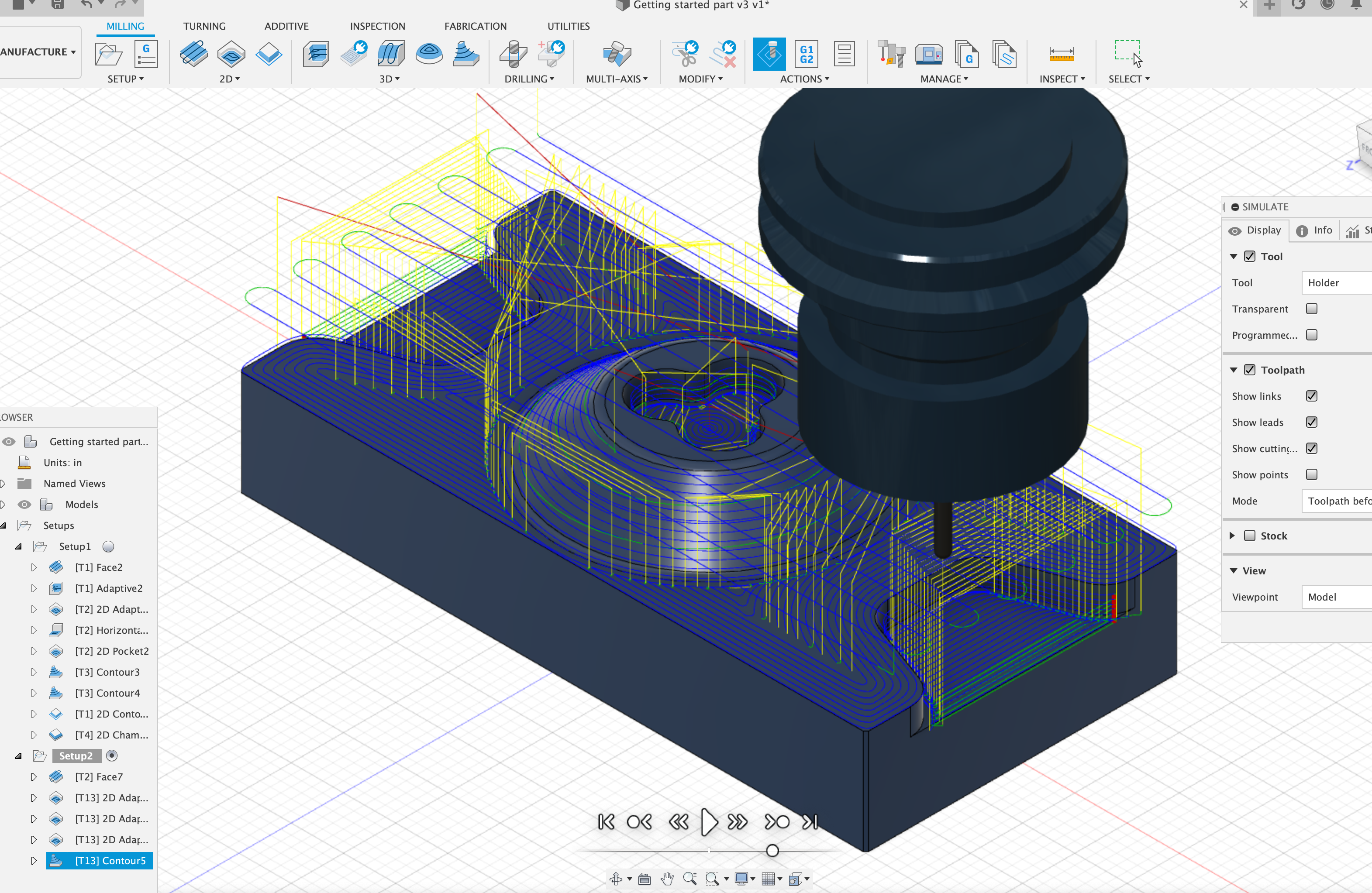
In this week we explored computer aided manufacturing (CAM) in Fusion 360. Besides the tutorial offered by Professor Jacobs, I found another useful tutorial on youtube:
For this assignment, I have tried to manufactured some of my original designs in Rhino, but somehow Fusion 360 cannot detect the pockets of my designs from the uploaded stl files, so I end up doing a manufacture of the example shape given in the youtube video.
Supplies
Fusion 360
Creating the Setup
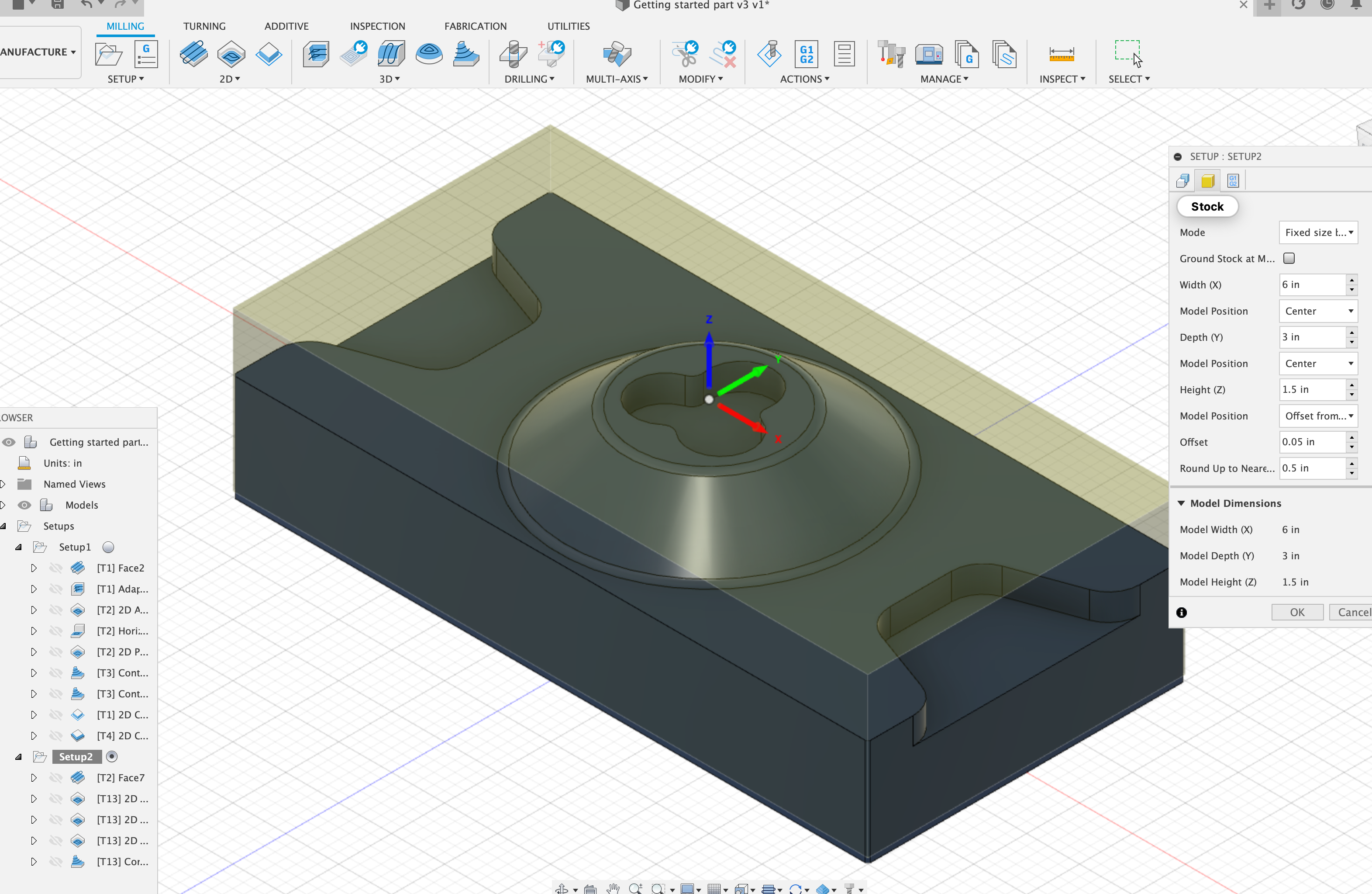
Due to the special shape of this piece, I decided to set the coordinate center at the center of this component instead of the corner. I set the z axis pointing upward to follow the convention and to make sure the mill is pointing downwards. I set the model position to be offset 0.05 inch from top to avoid possible artifacts when manufacturing. This completes the initial setup, and the next step is to create facing toolpath.
Creating the Facing Tool Path
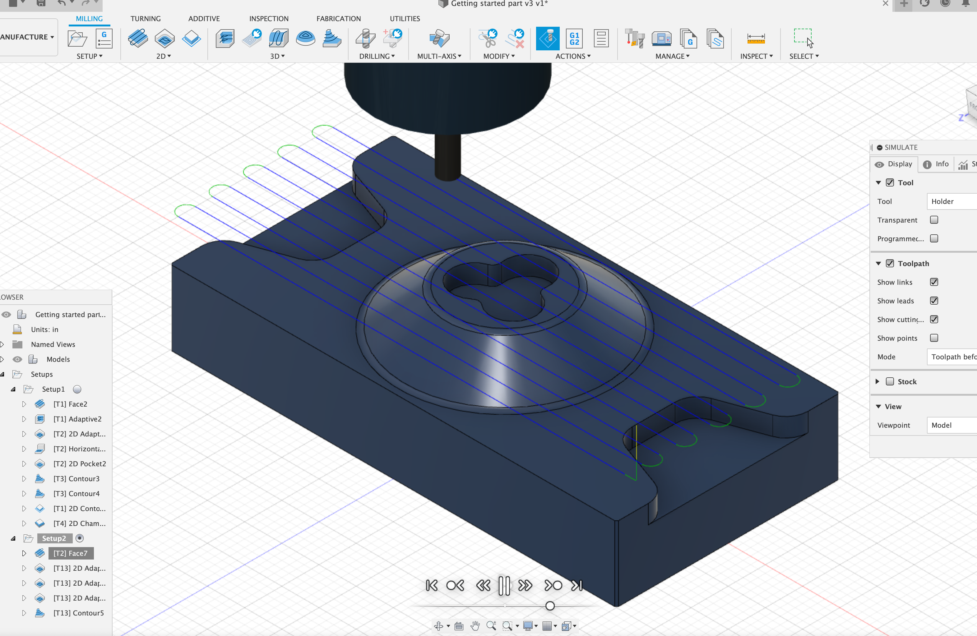
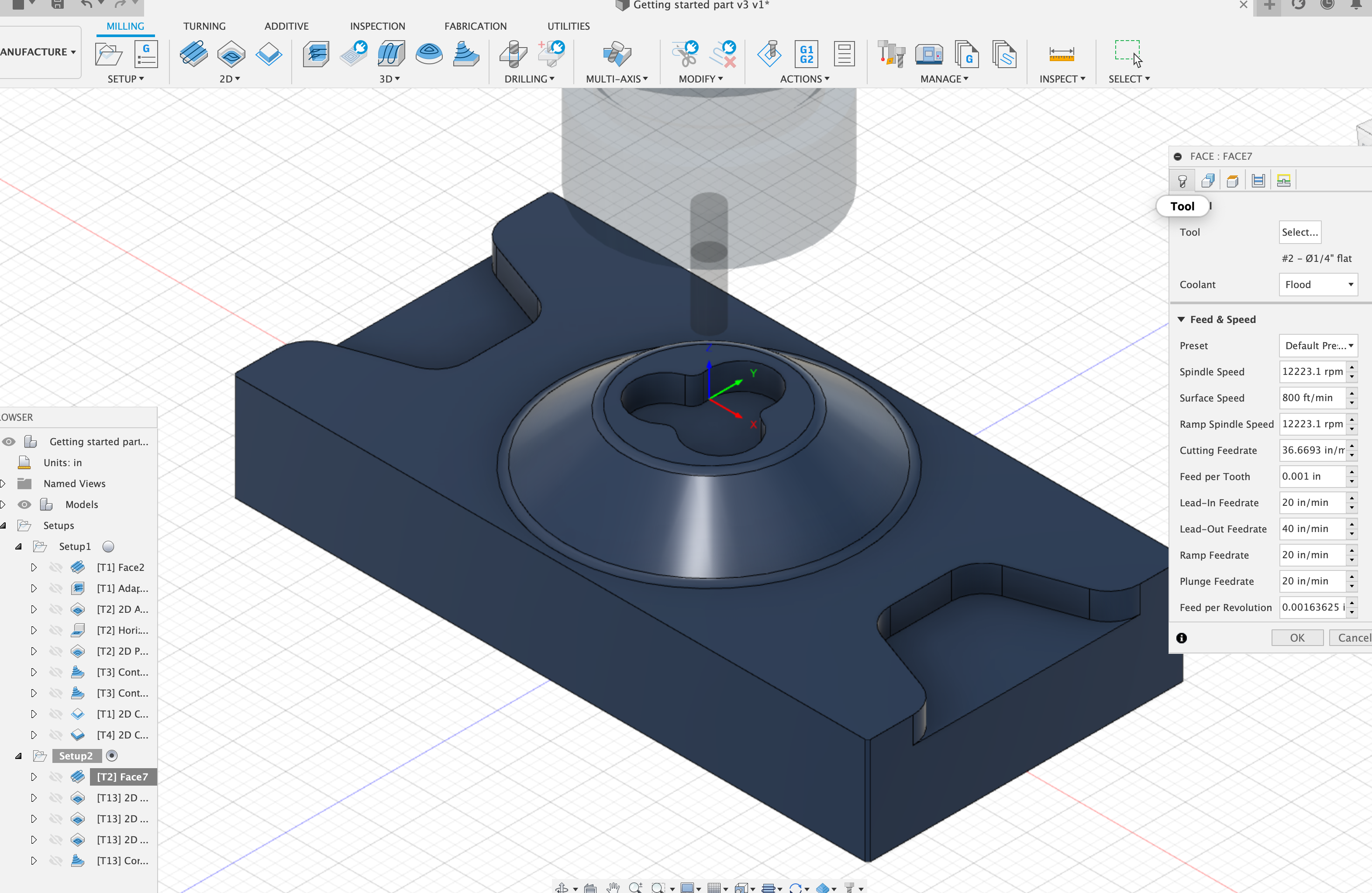
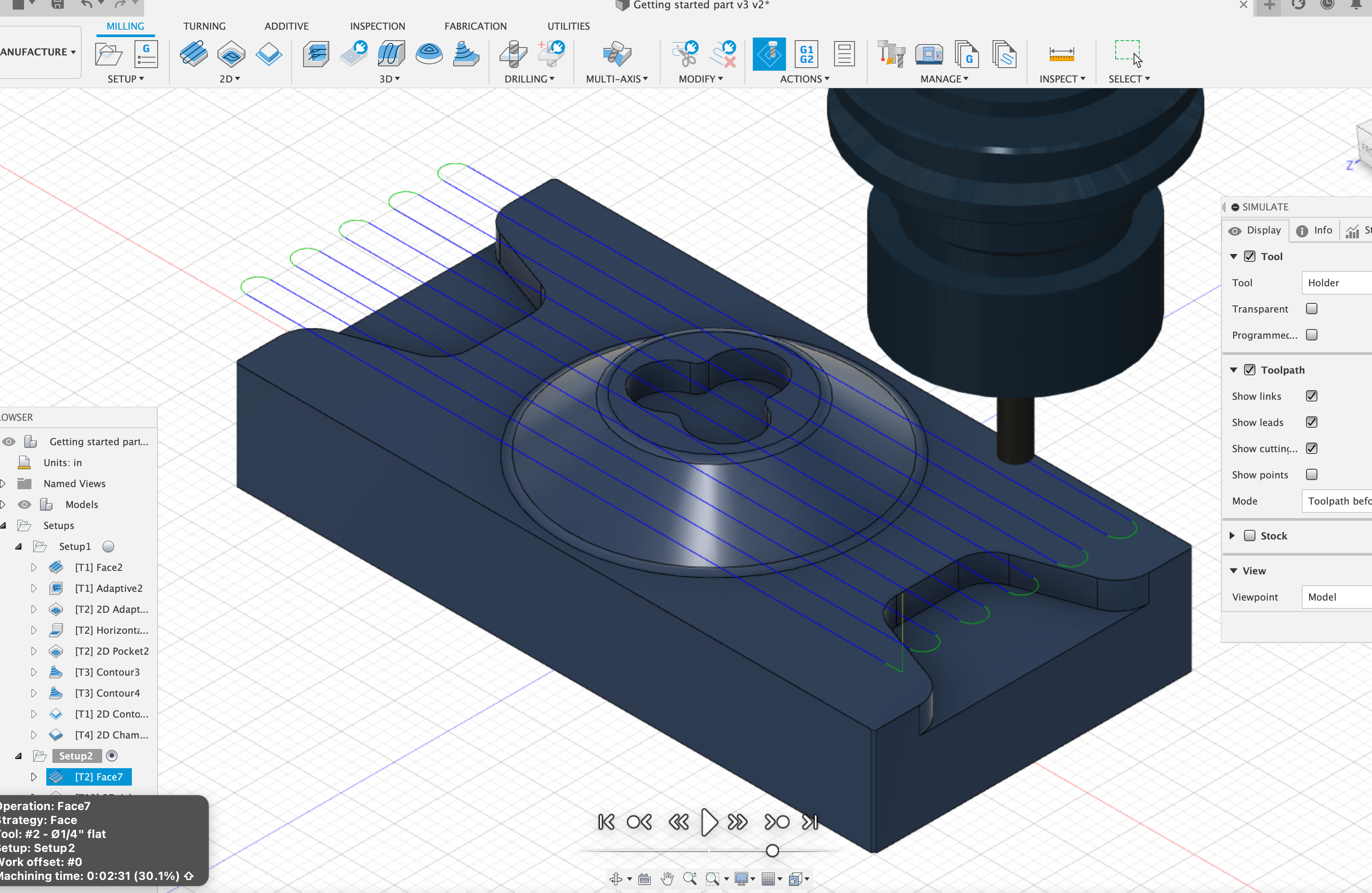
To create the facing toolpath, I selected a 1/4 inch flat mill initially because I do not really know the size of this component. In order to save time and energy, we can use a larger flat mill. After completing the facing tool path, we can move on to 2D adaptive clearing. Since this component is not purely 2D as there is a hill like structure in the middle, I also need to include 3D adaptive contour.
2D and 3D Adaptive Clearing
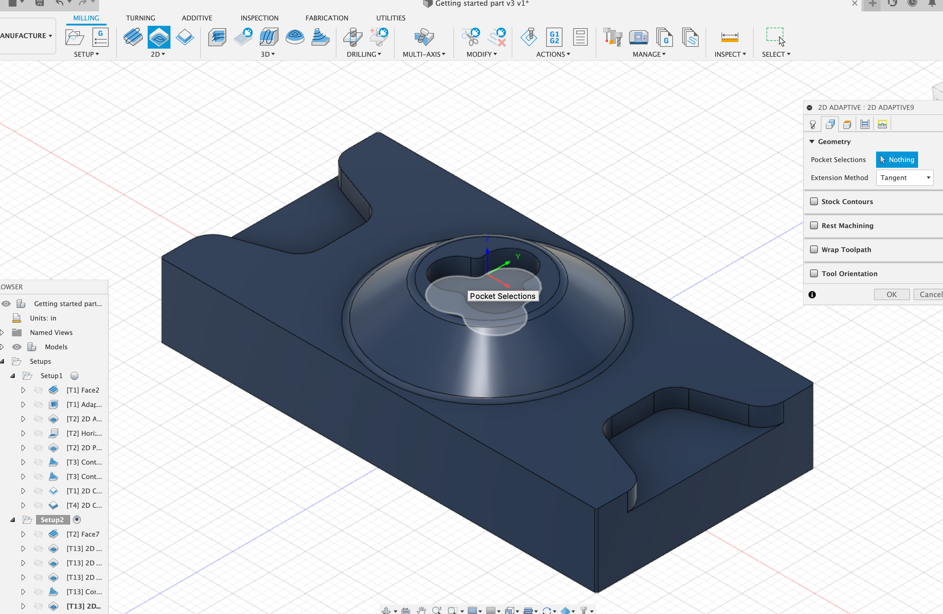
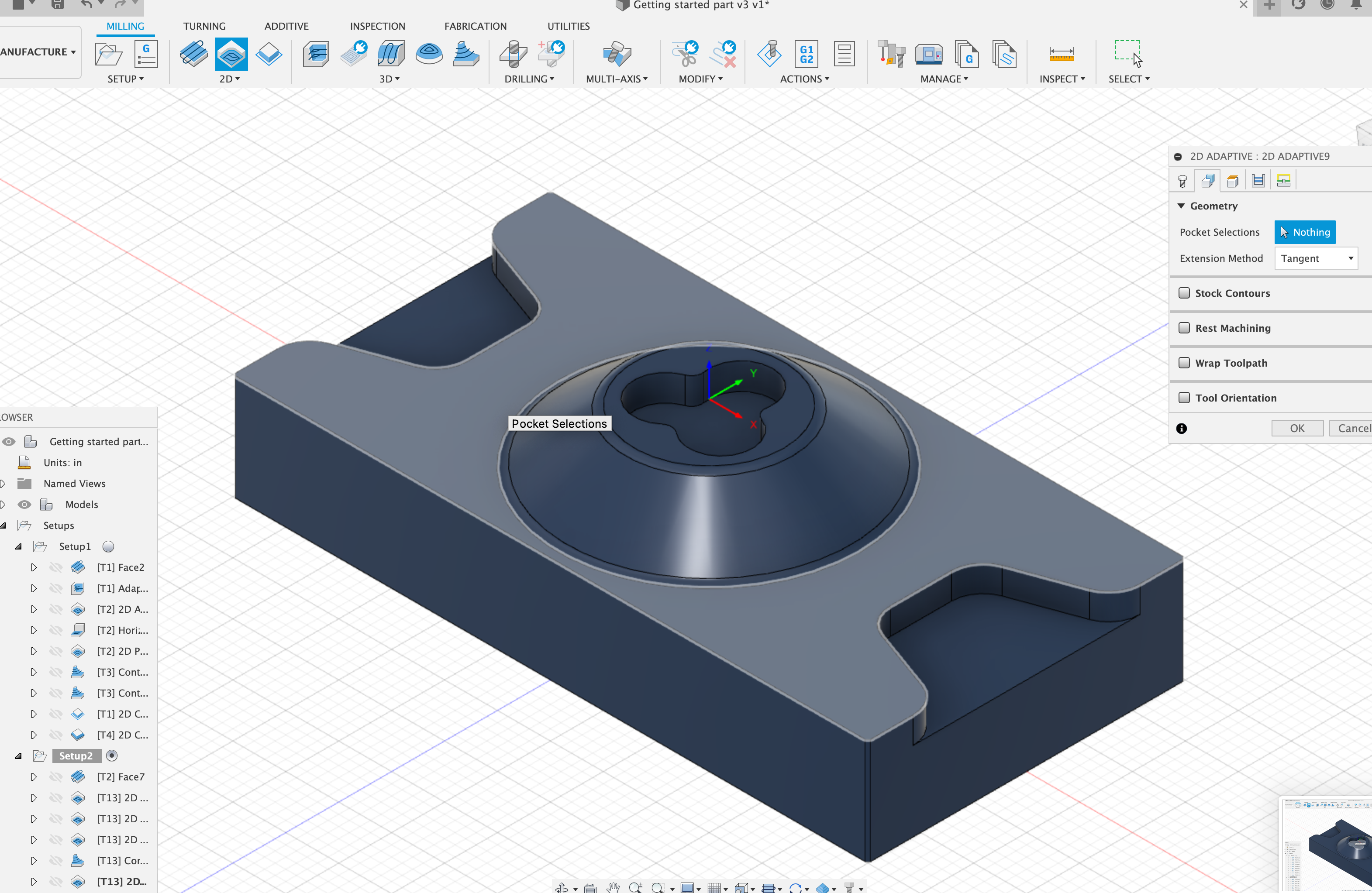
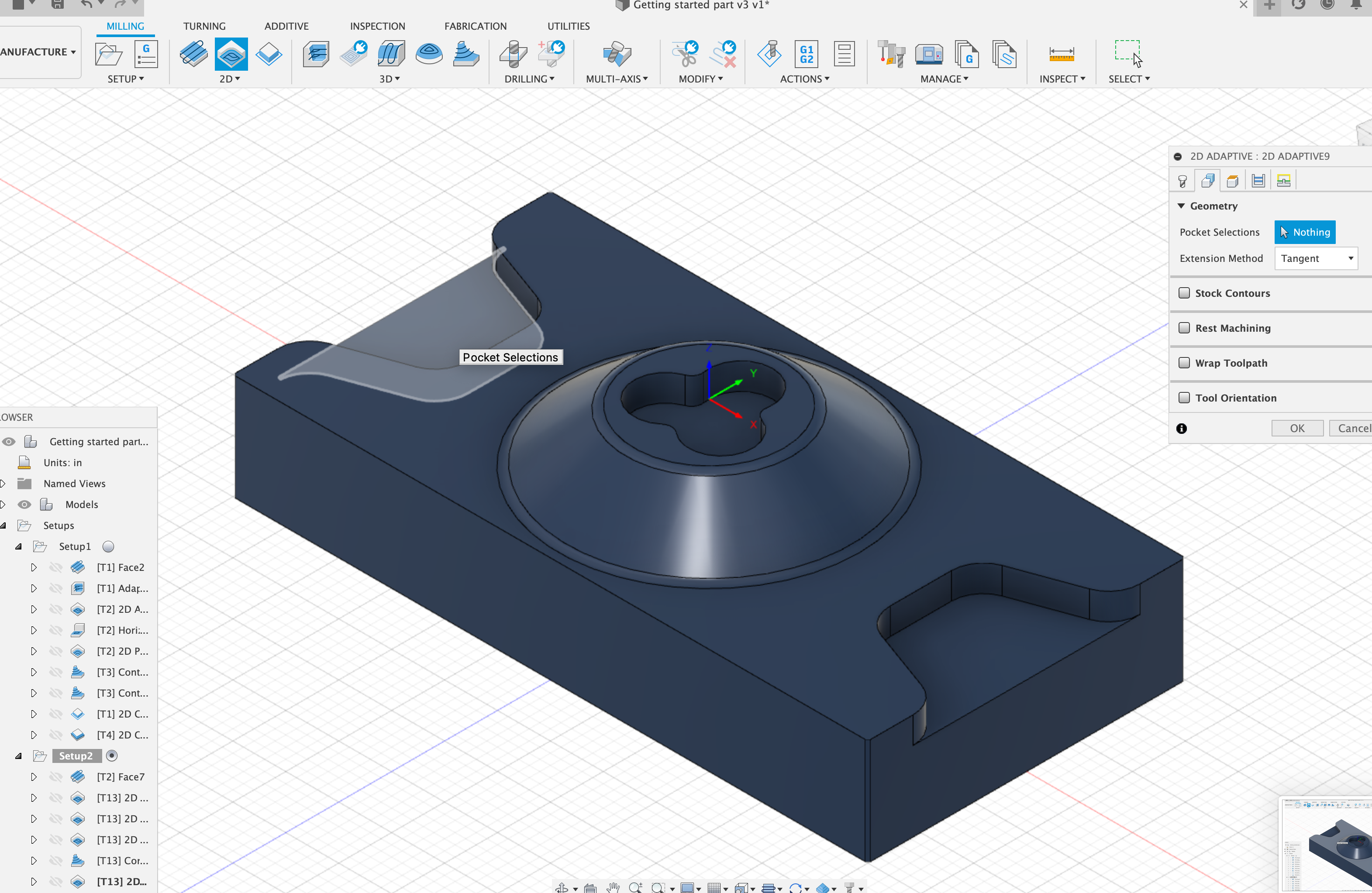
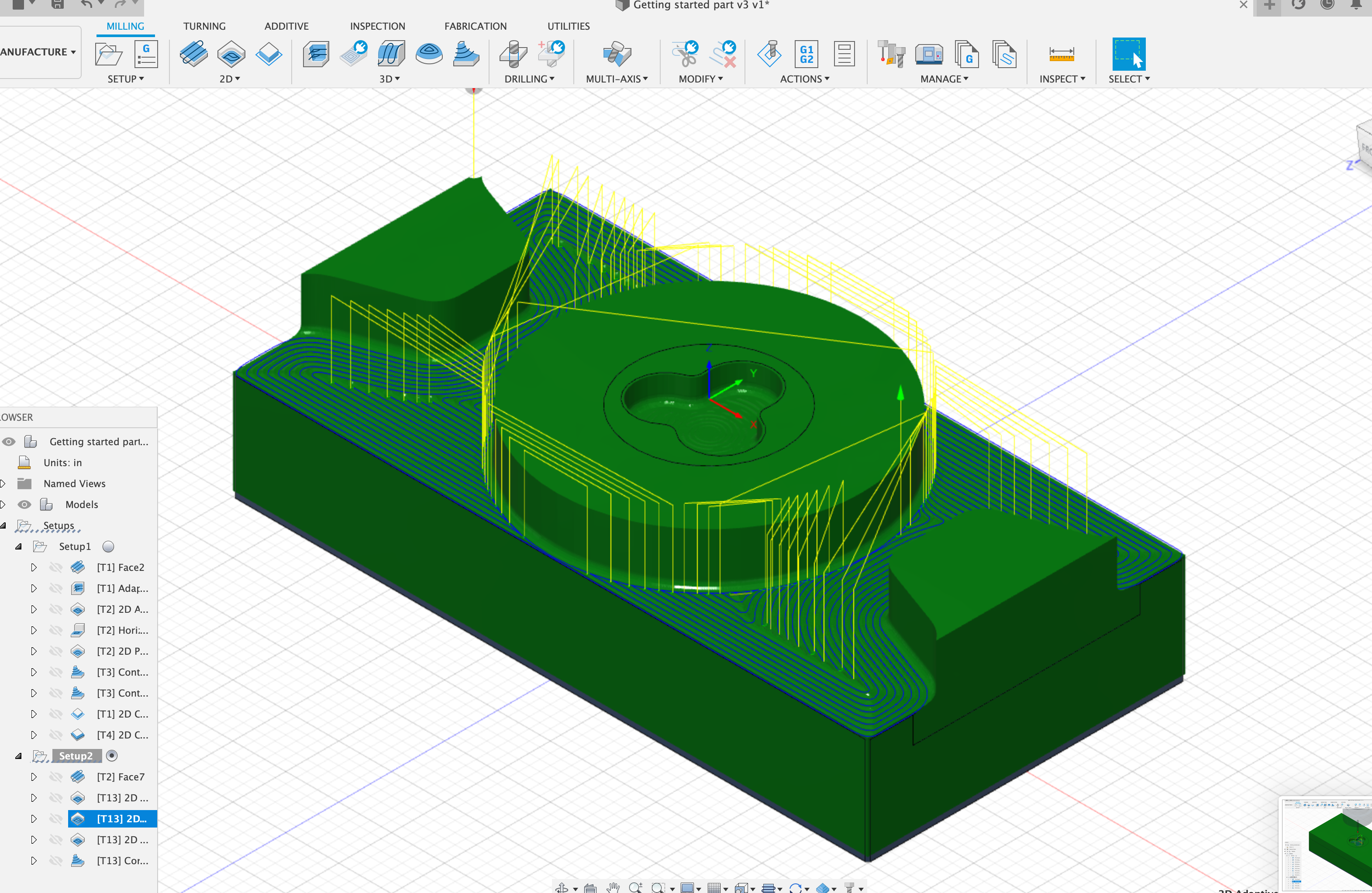
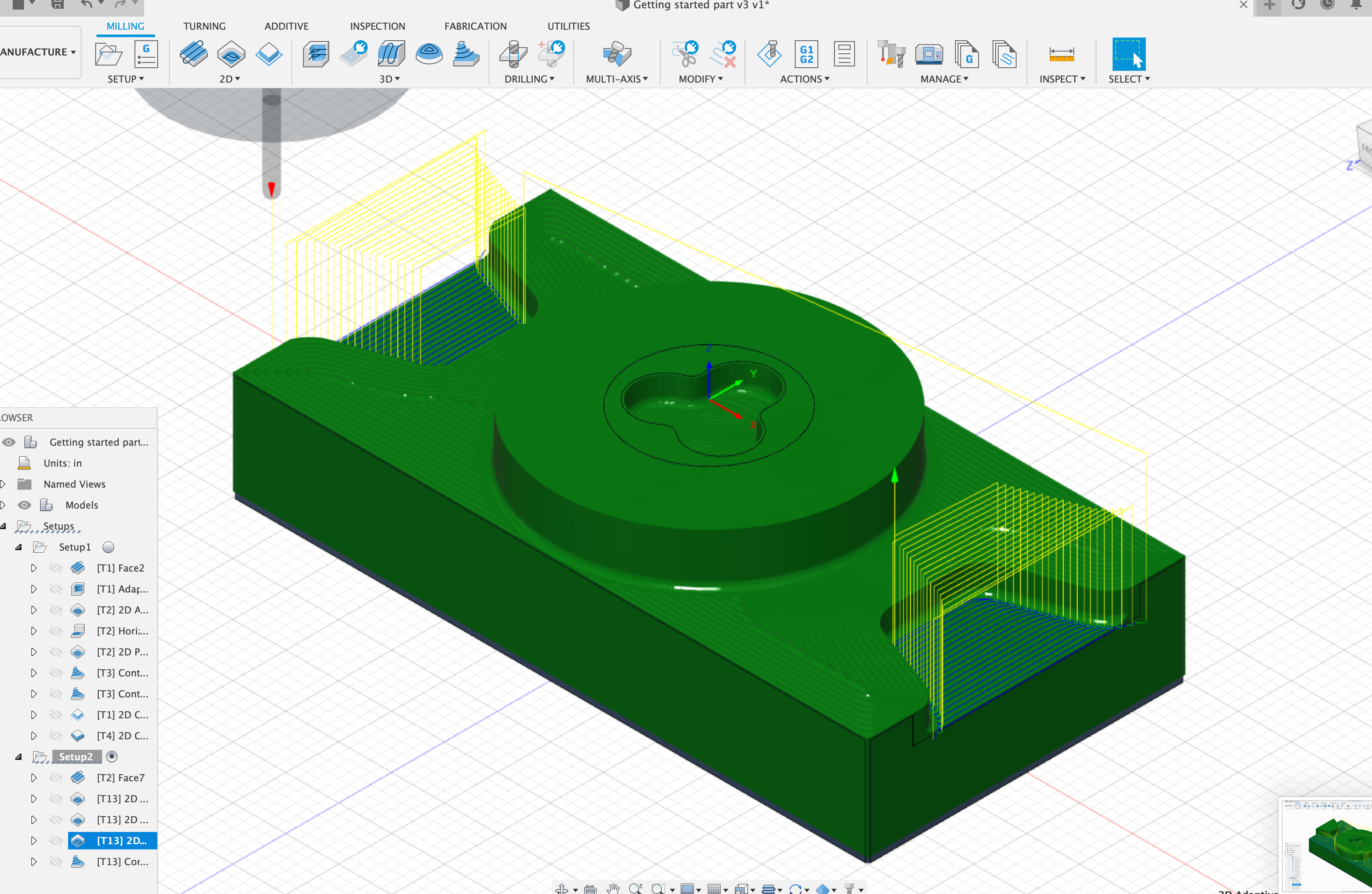
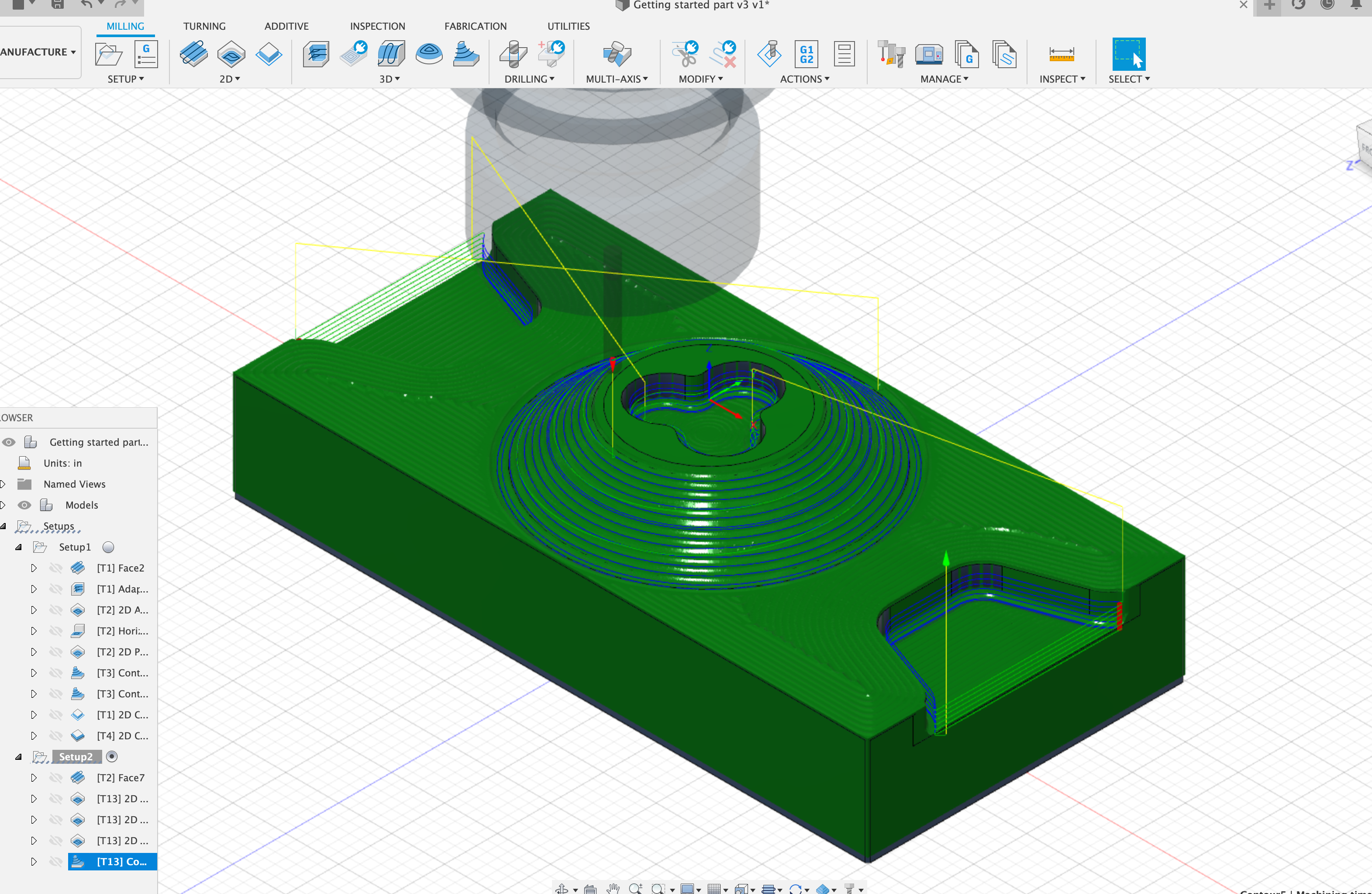
The reason why I cannot use my designs in the previous weeks is when I upload the stl files, Fusion cannot recognize the pockets in the design, so I switch to this Fusion based component.
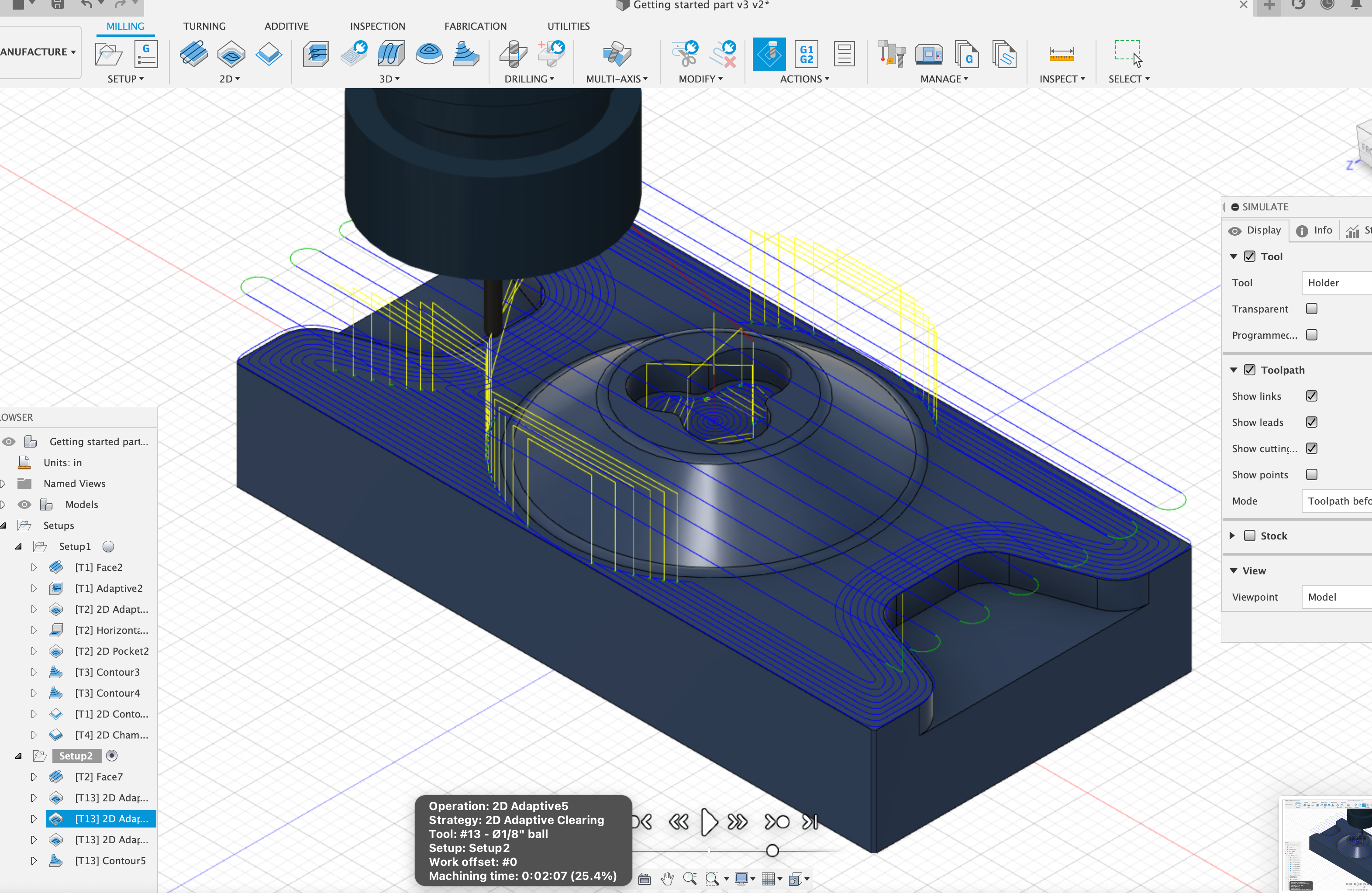
For this component, we can see there are 3 pockets, and I chose a 1/8 ball mill to do the drilling.
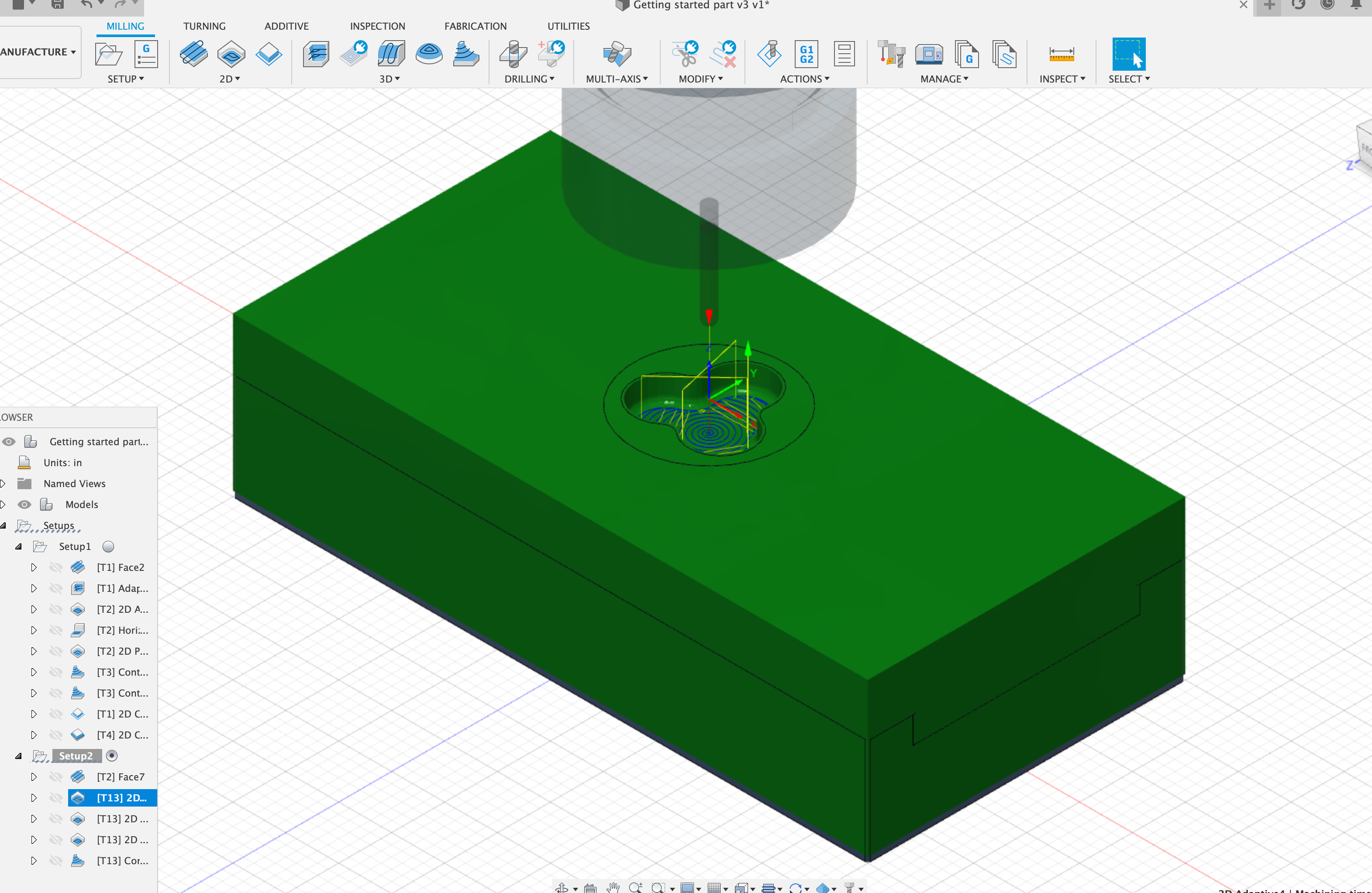
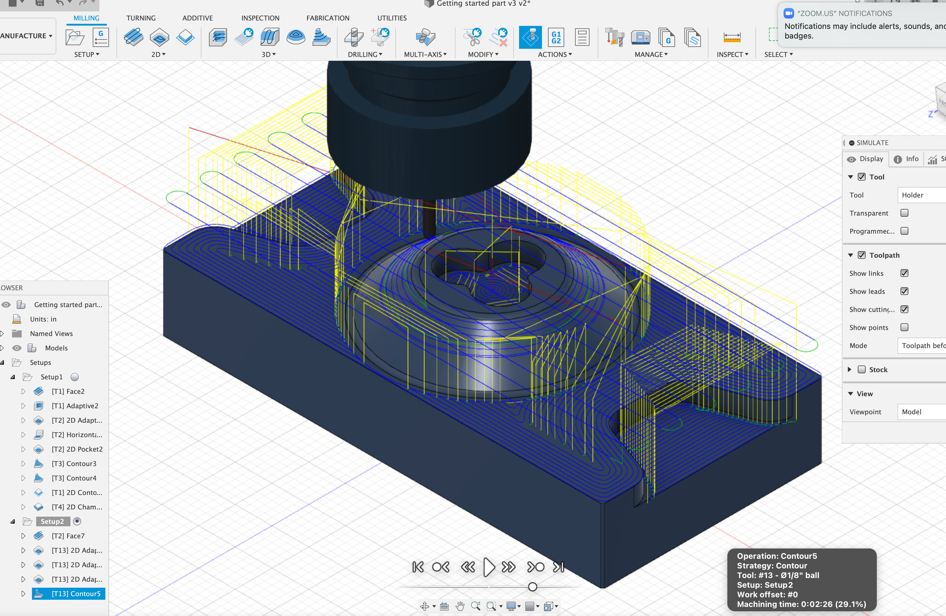
The last part is the hill-like structure. I used contour in the 3D section to do that, and the basic idea is to divide the hill into multiple cylinders with increasing heights to mimic the shape. This completes the manufacturing process.
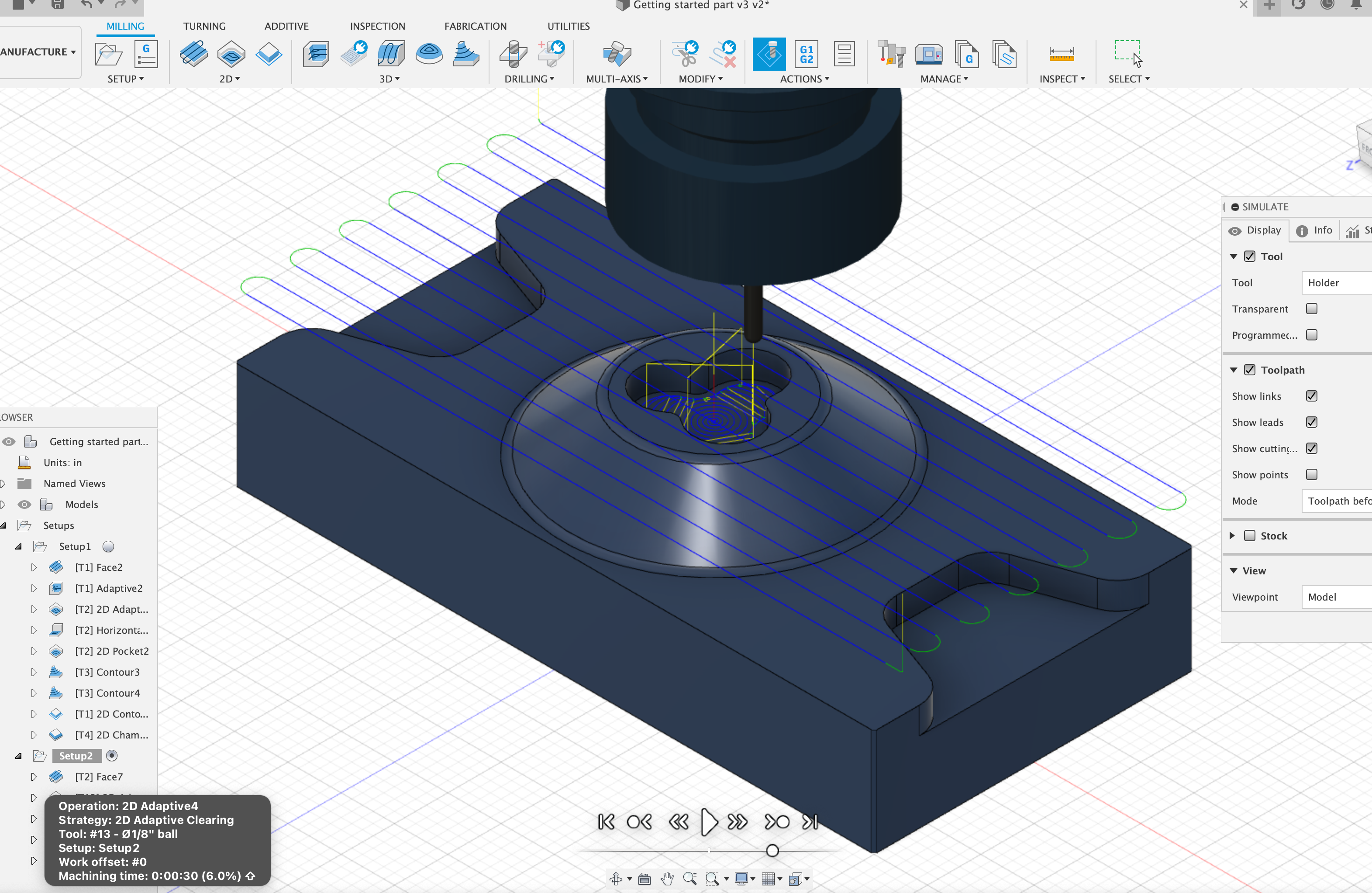
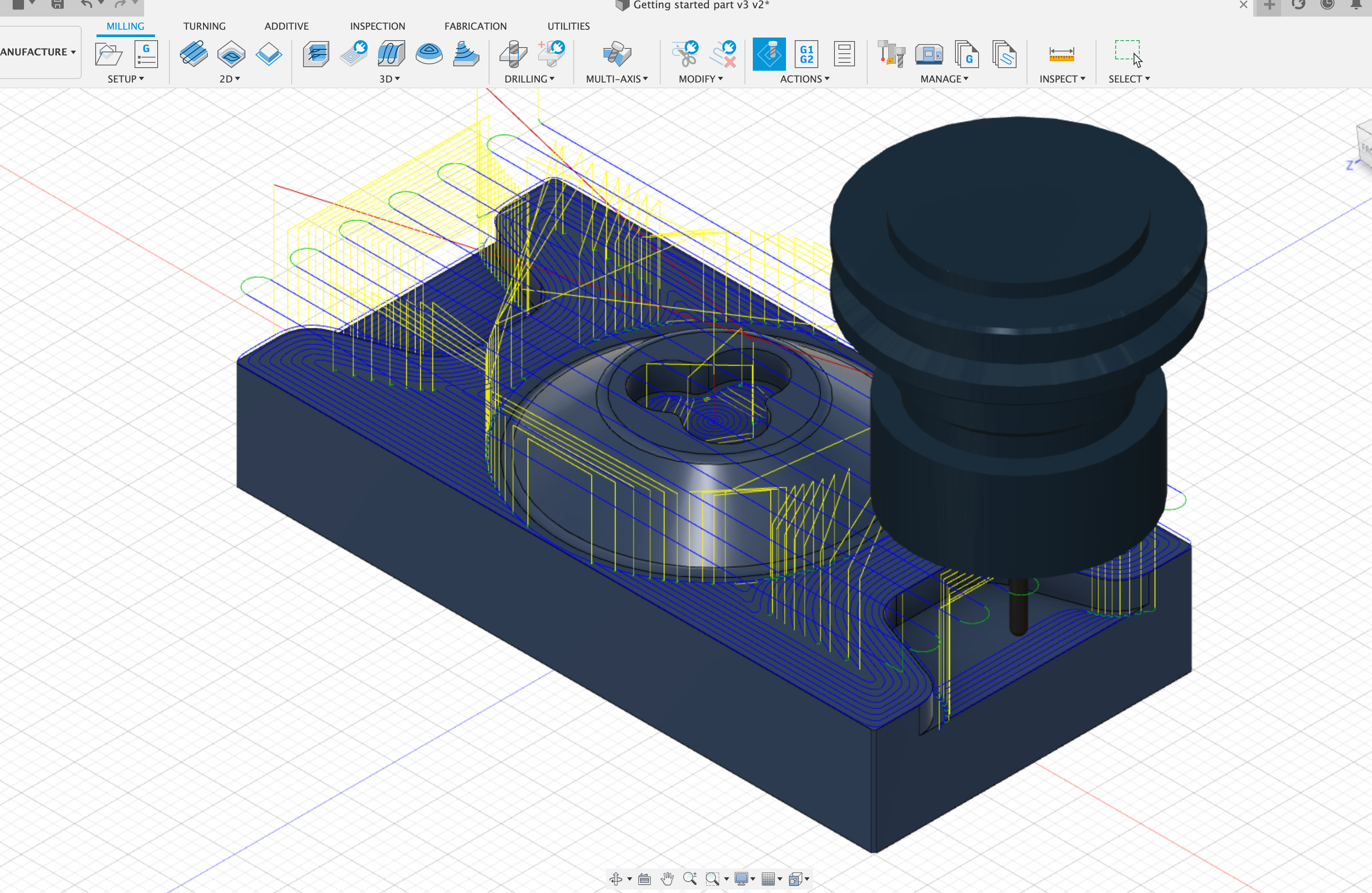
Screenshot of the Manufacturing Process

^