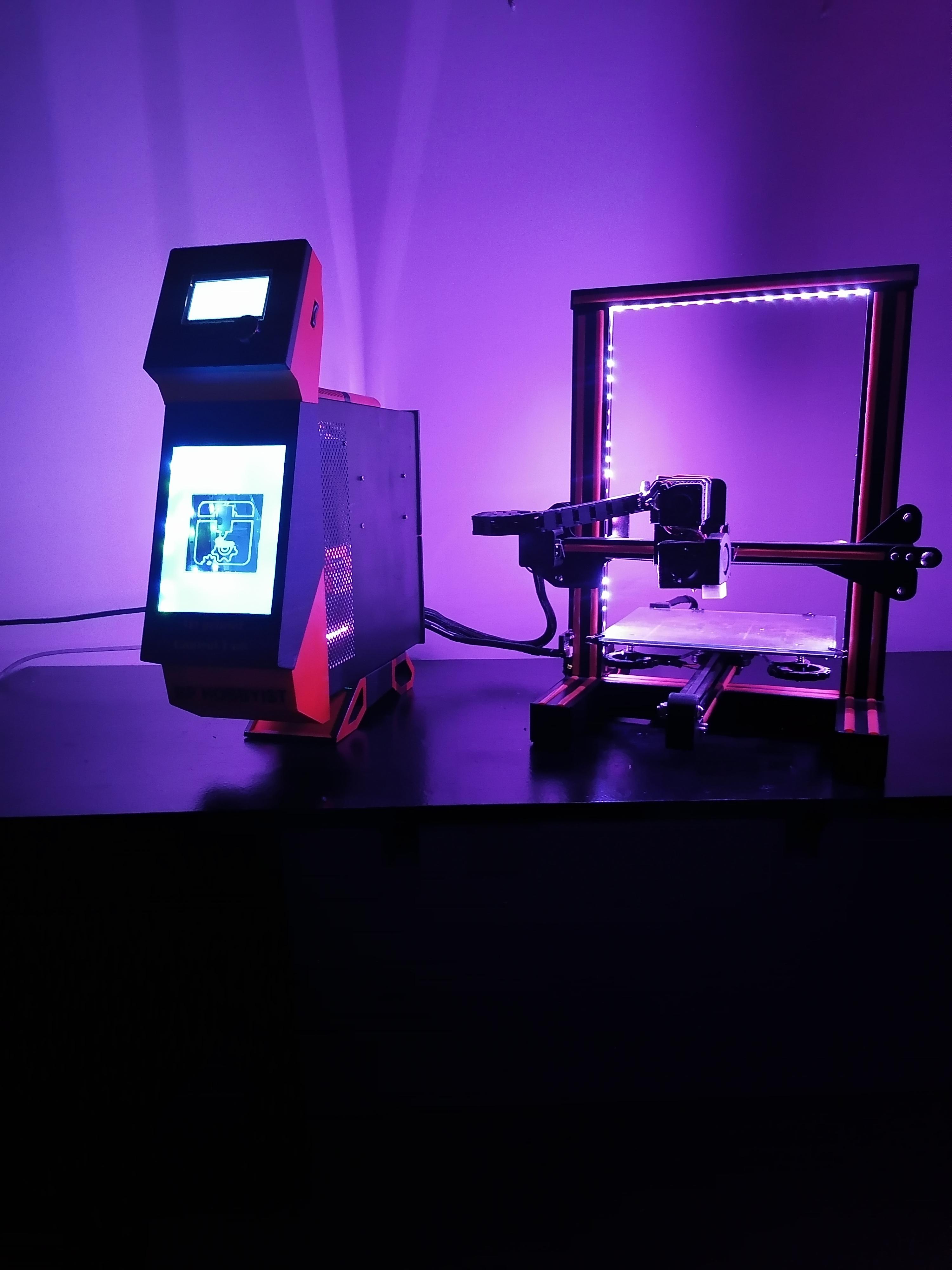
DIY Upgrade 3D Printer
by RP HOBBYIST in Workshop > 3D Printing
3413 Views, 32 Favorites, 0 Comments
DIY Upgrade 3D Printer


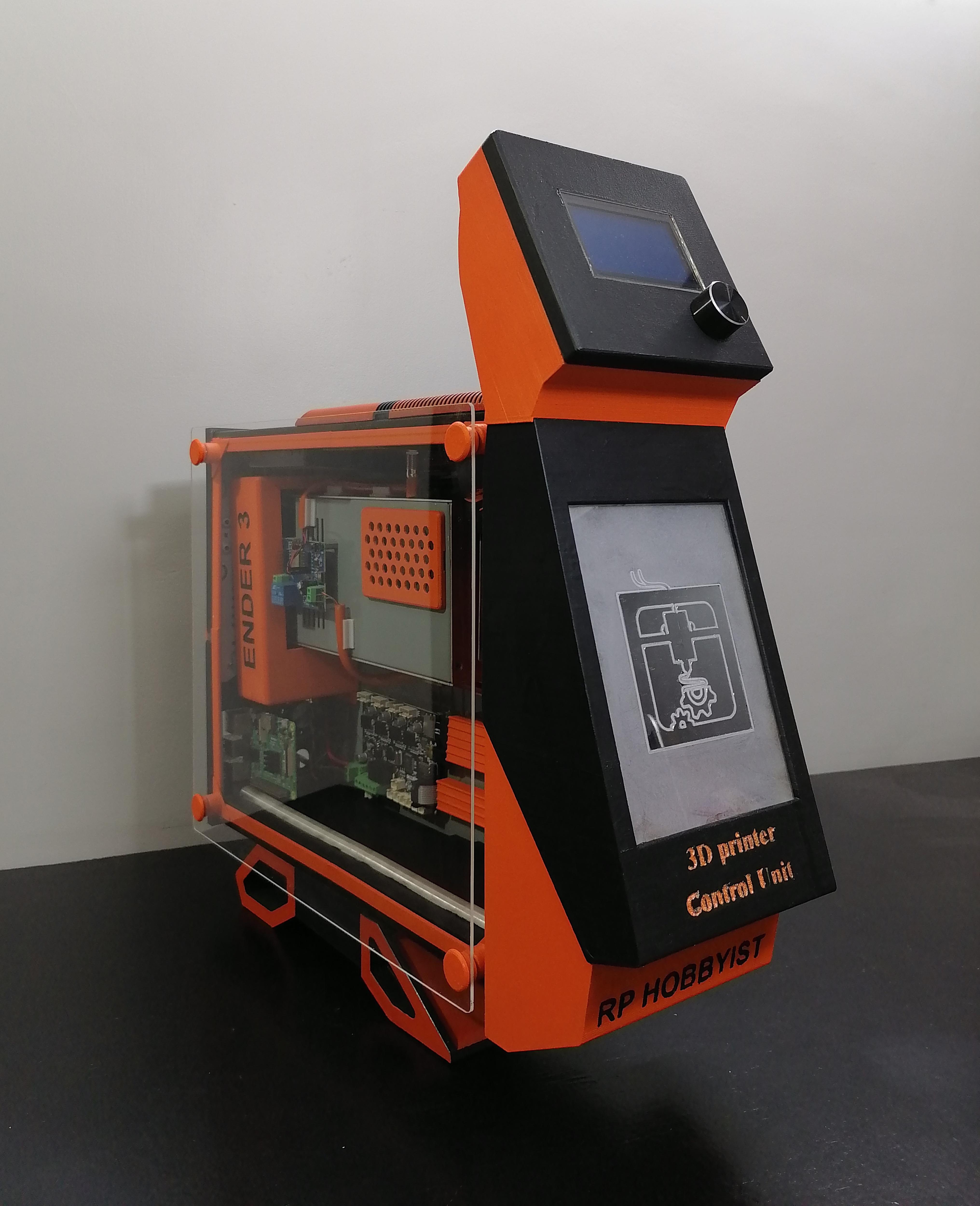
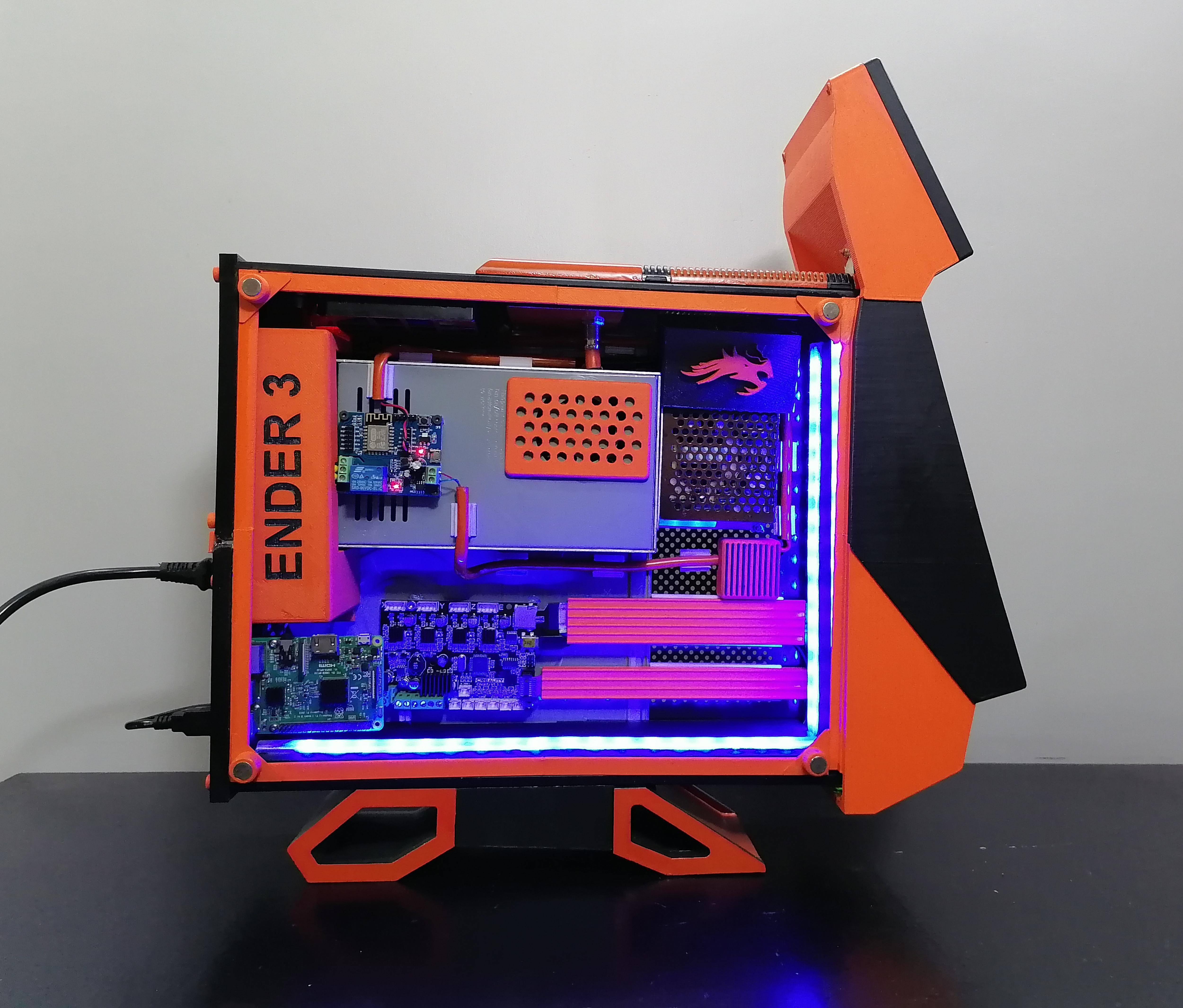
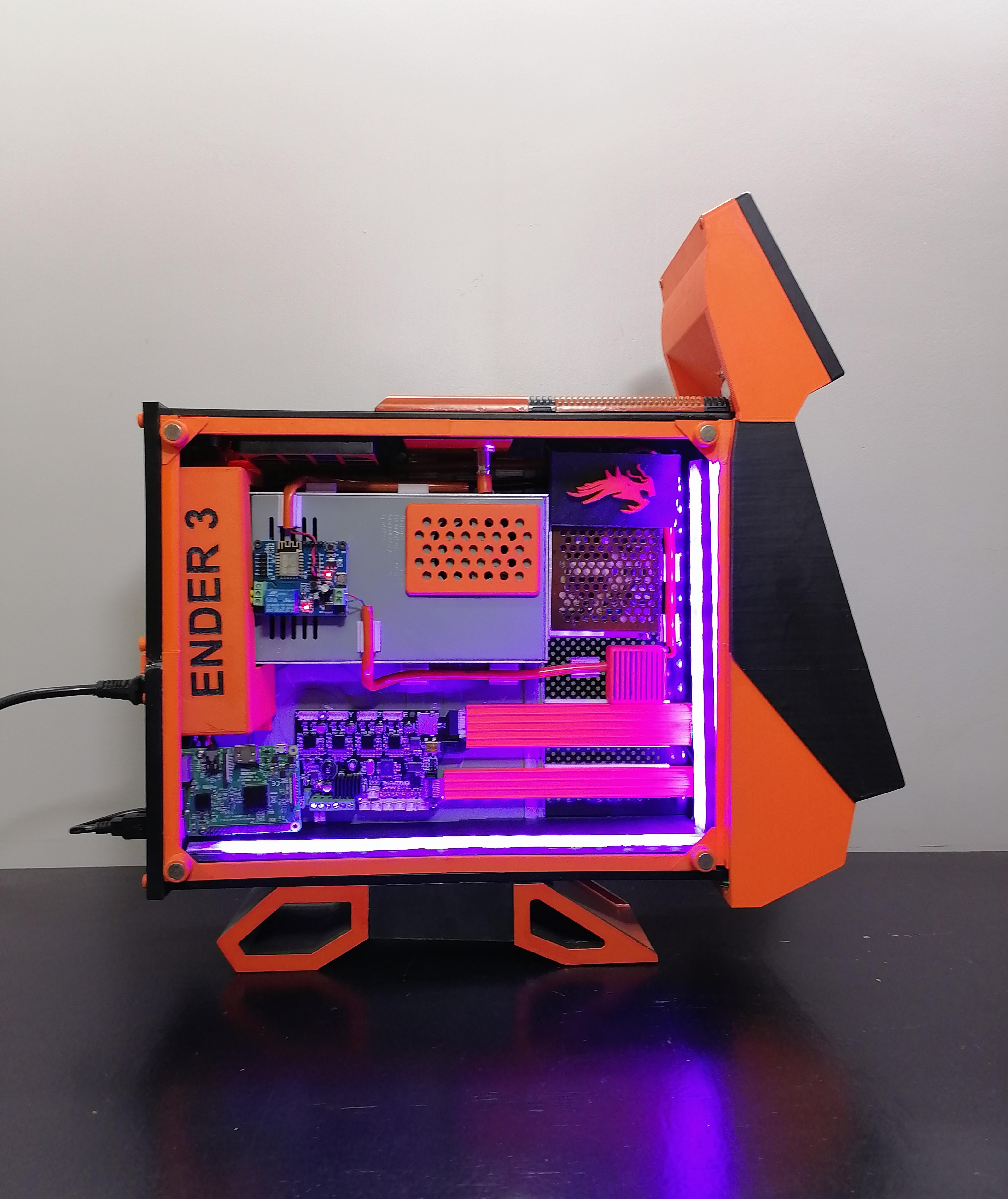
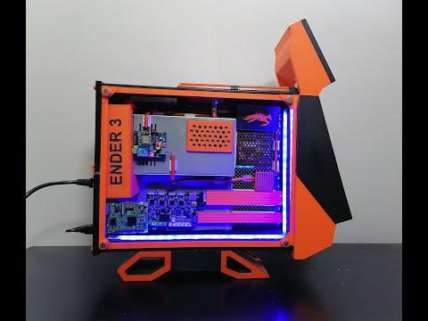
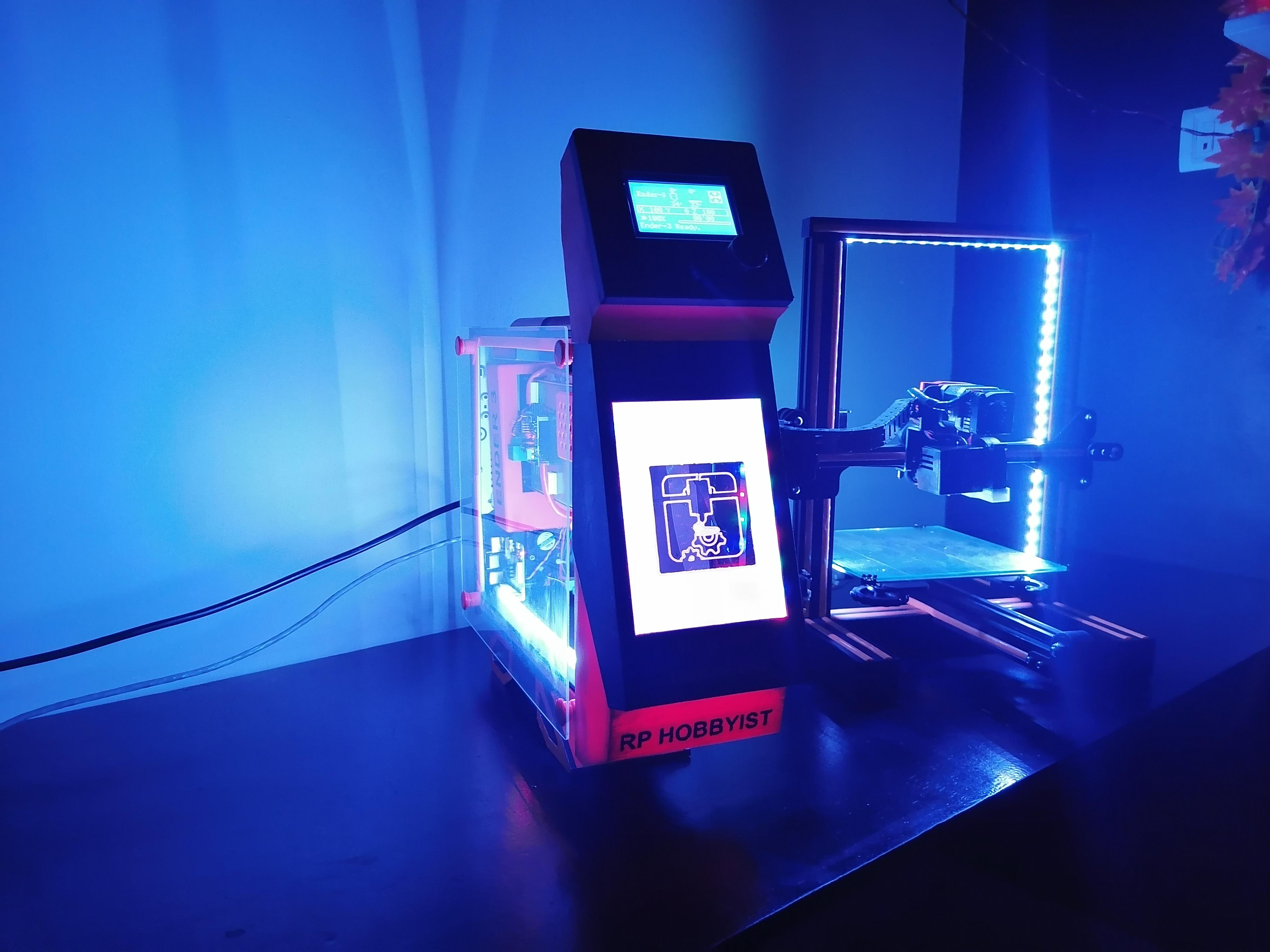
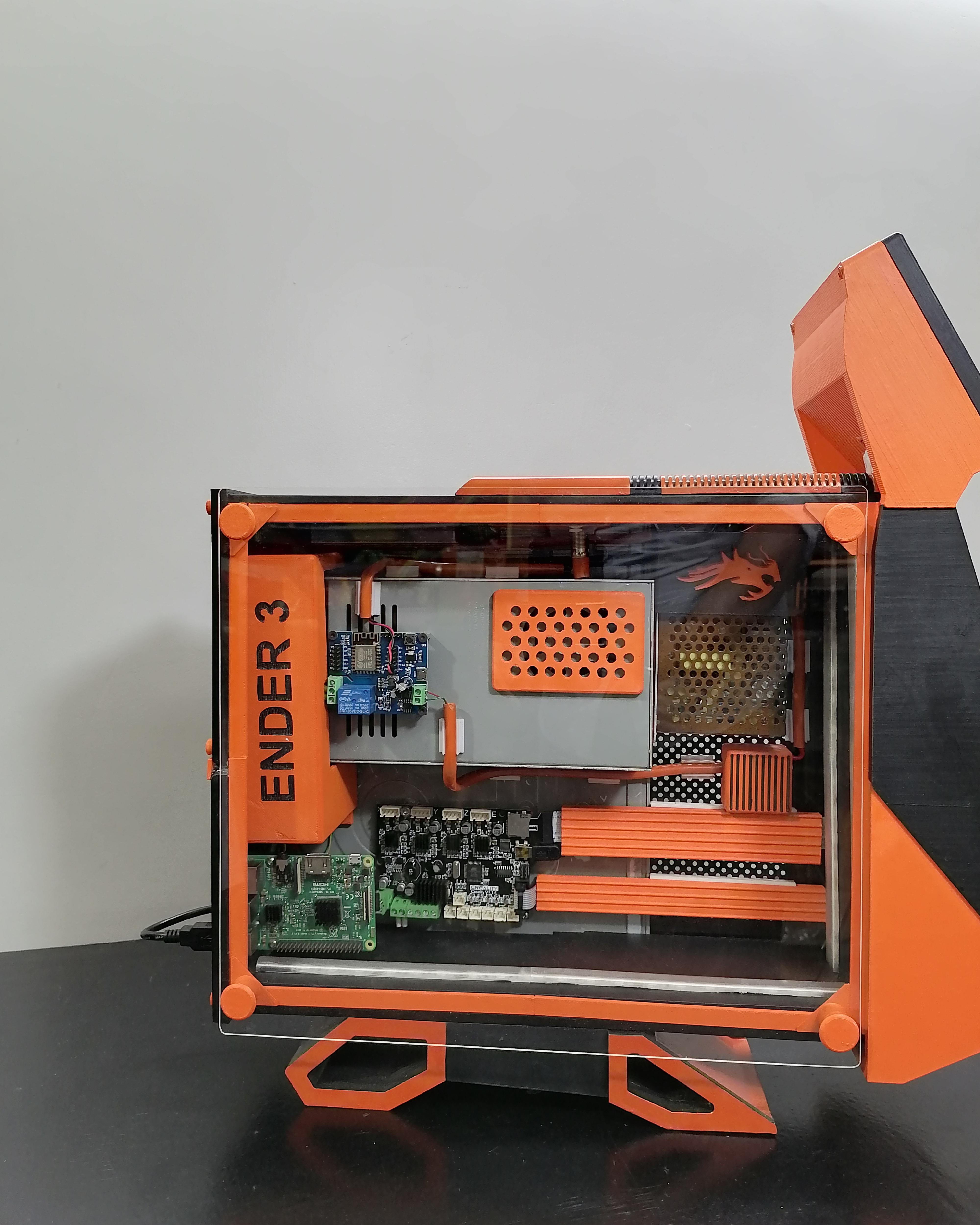
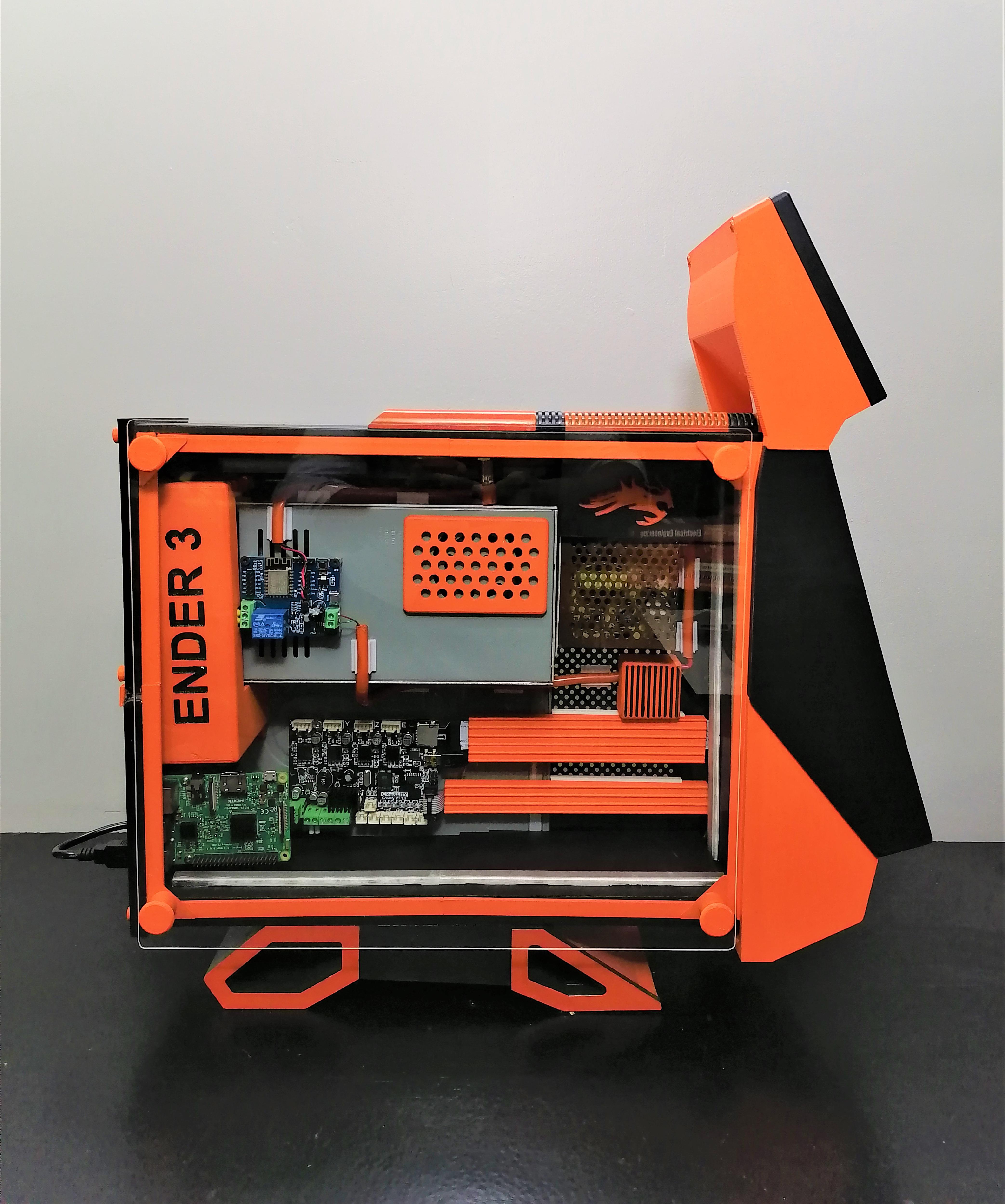
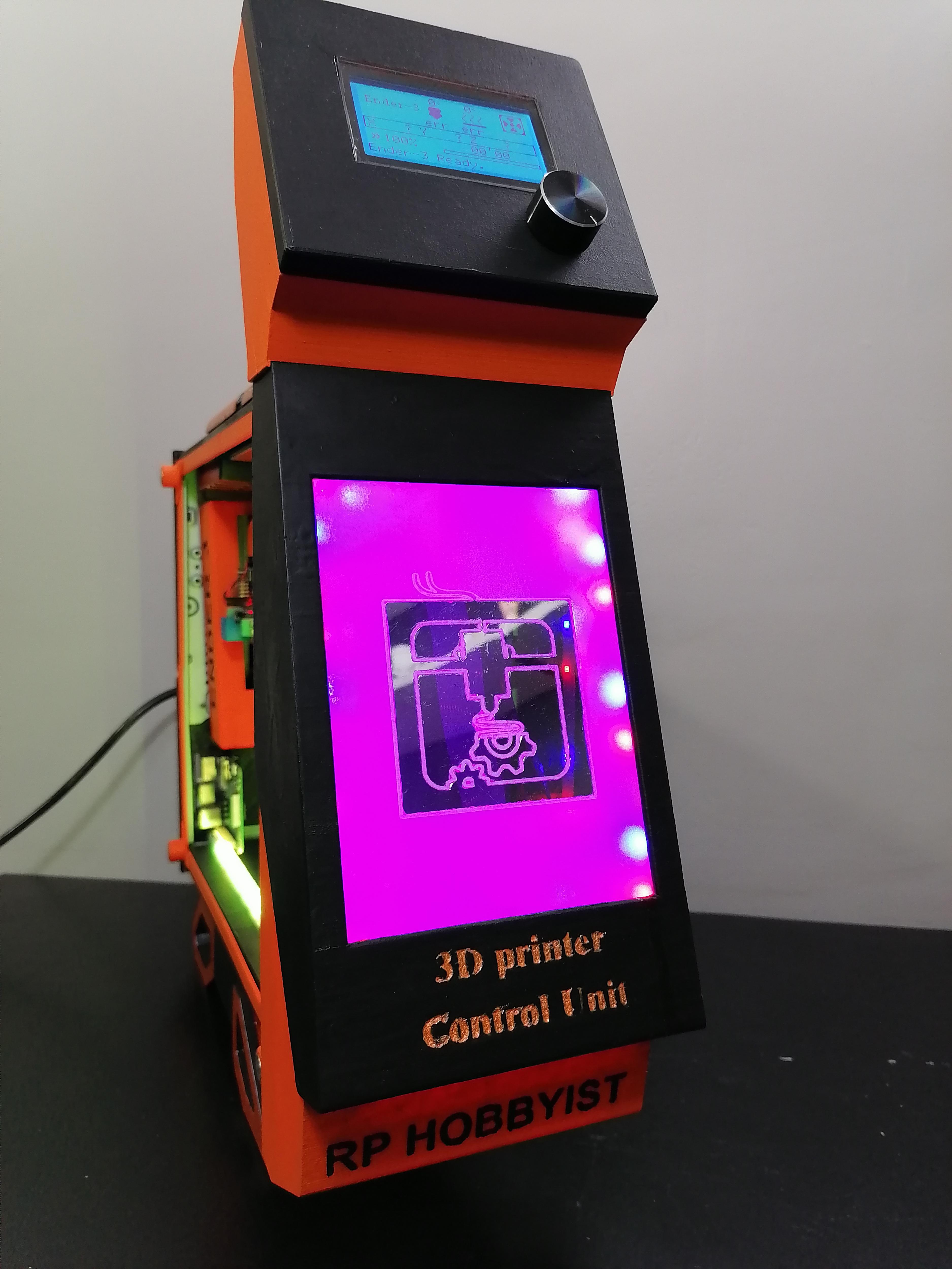
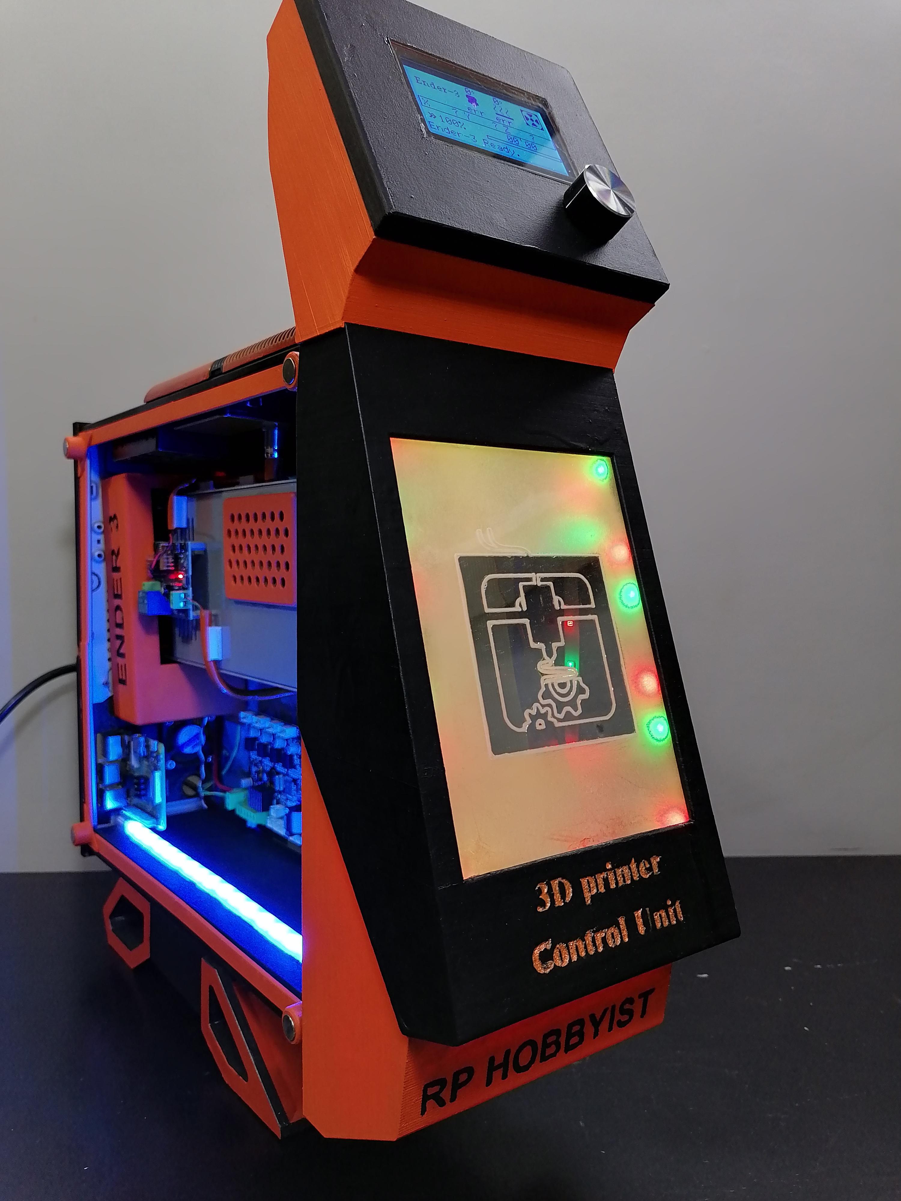
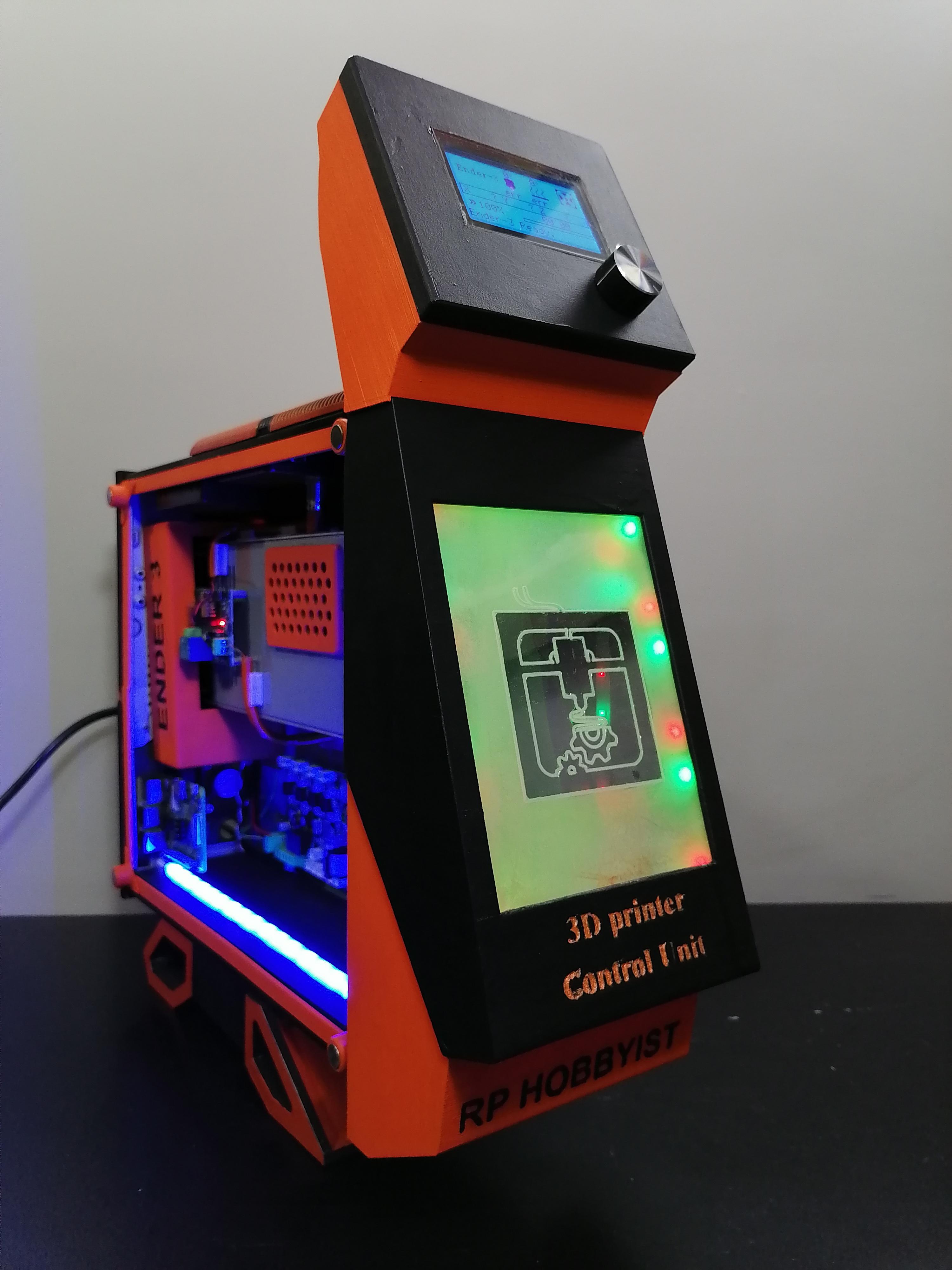
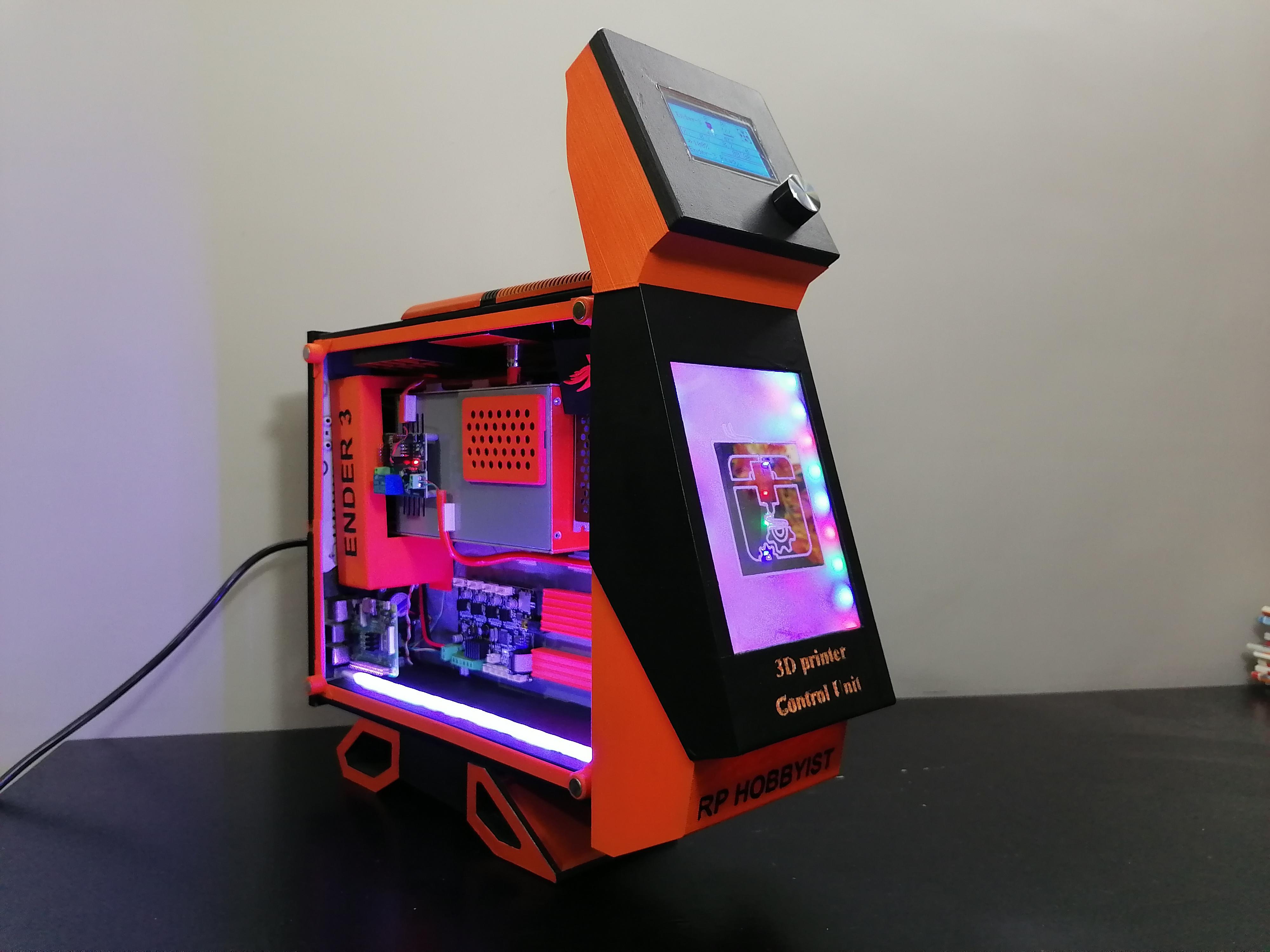
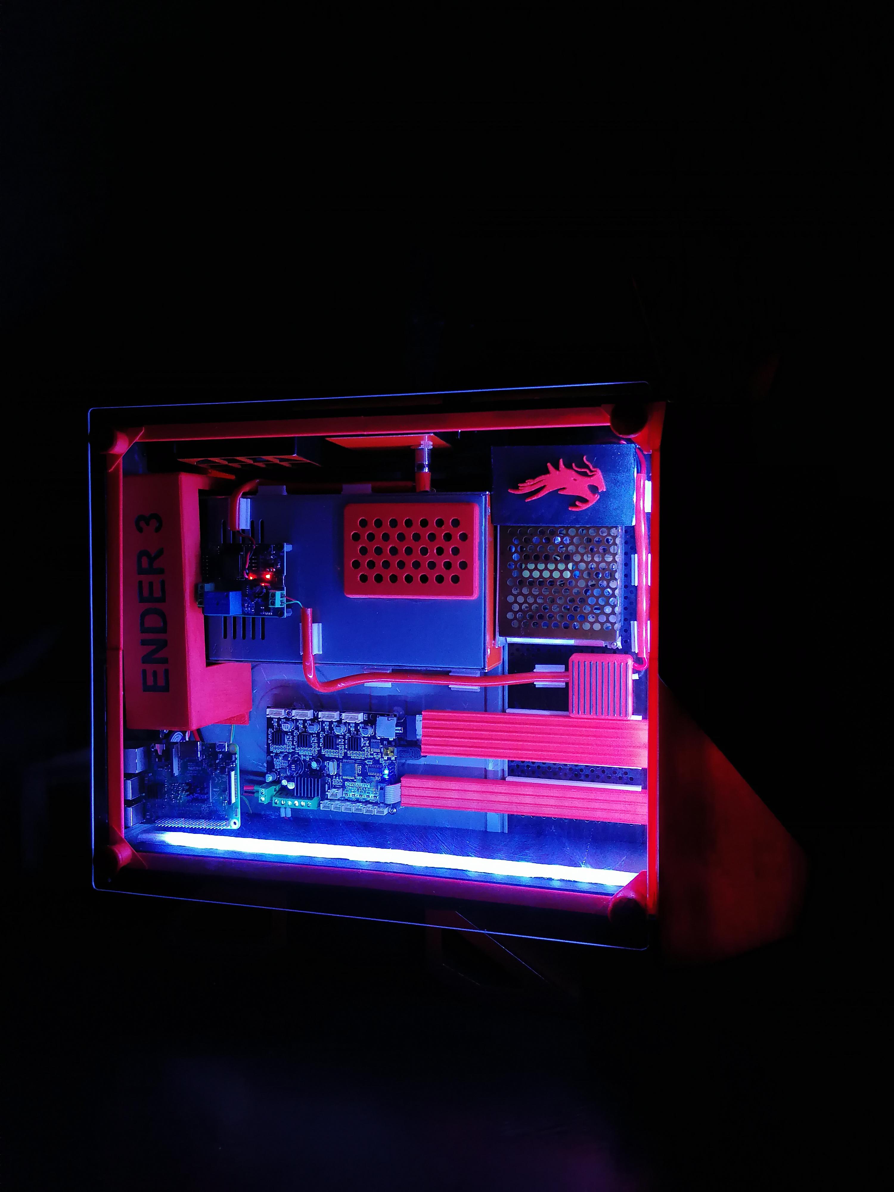
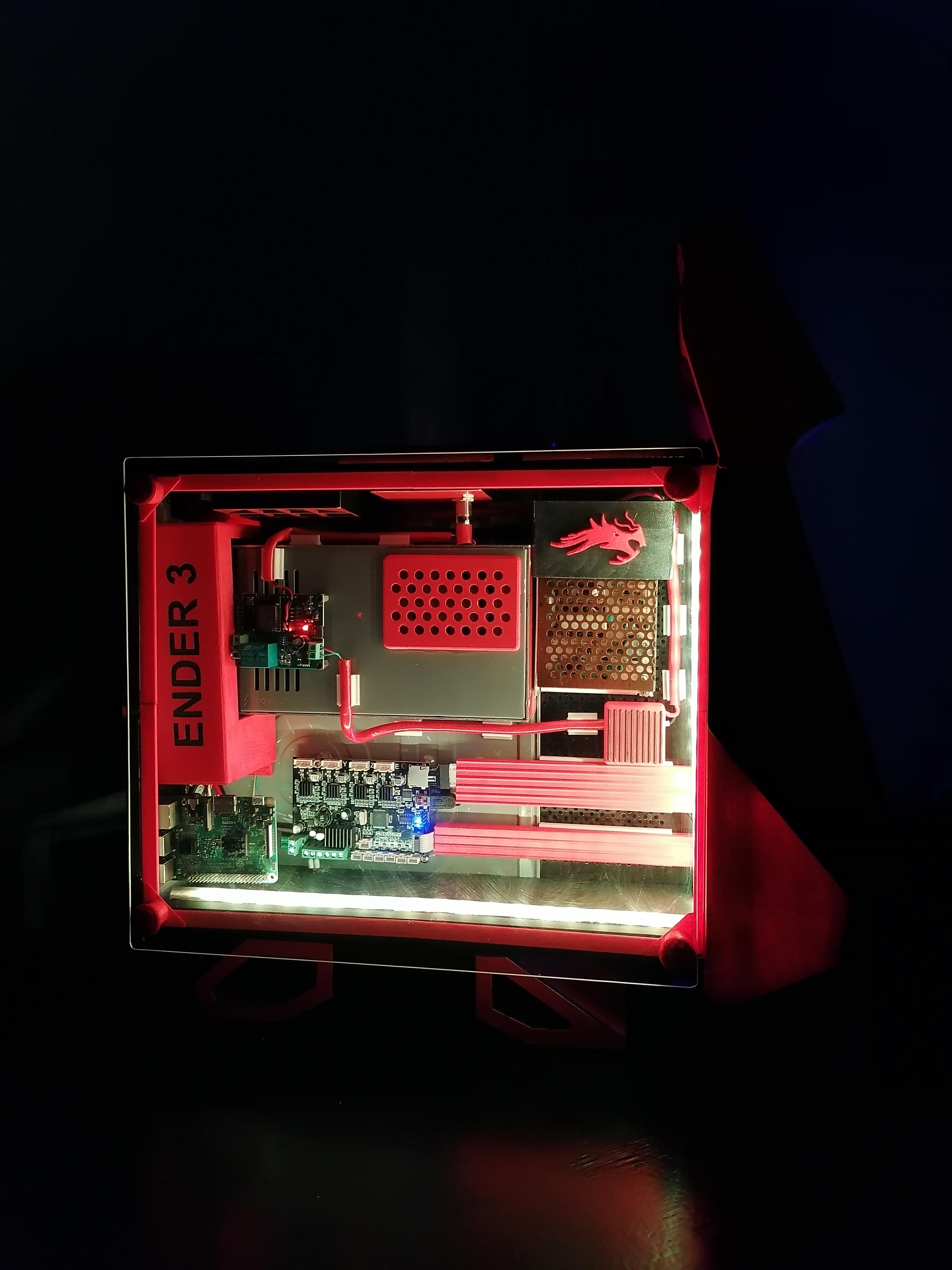
Mostly all majors’ upgrades have been done by the 3d Printer community so I was thinking that what is left to make a new upgrade. Here I am upgrading the Creality Ender3 3D Printer. All 3D Printer owners are bored of their 3D Printer, the reason is body design is not meet the Modern look. We all want our printer to have a modern design. So I took all electronic parts from printer namely Power Supply, Main Board and Screen. All these components and extra others are placed in the CPU Case. To look modern I converted the old CPU case into the Control Panel of the 3D Printer. 3D printed the Exterior and Interior parts to look like a gaming CPU.
Features:
-WiFi Controlling
-Octopi in-built using raspberry Pi 3-B
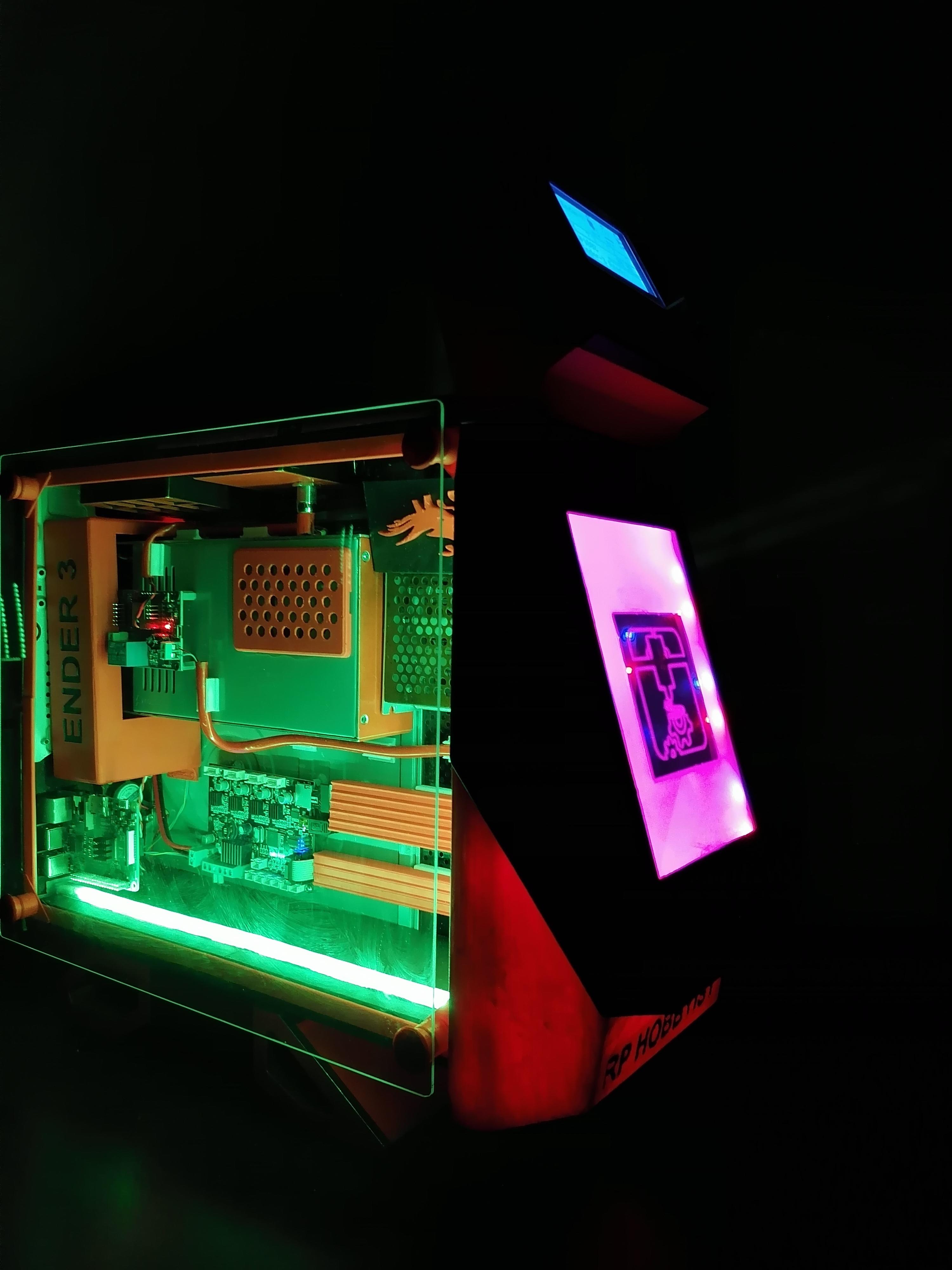
-RGB Light Bluetooth Control
-Modern Look
Supplies


Here below download the BOM File.
Downloads
Design in Fusion360
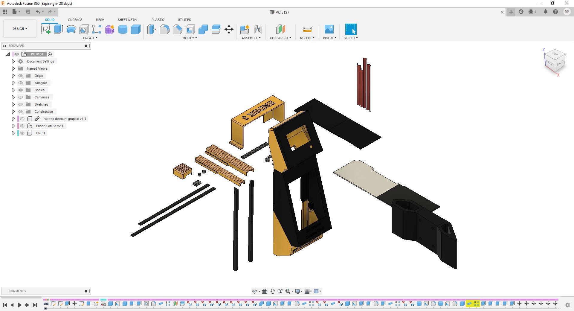
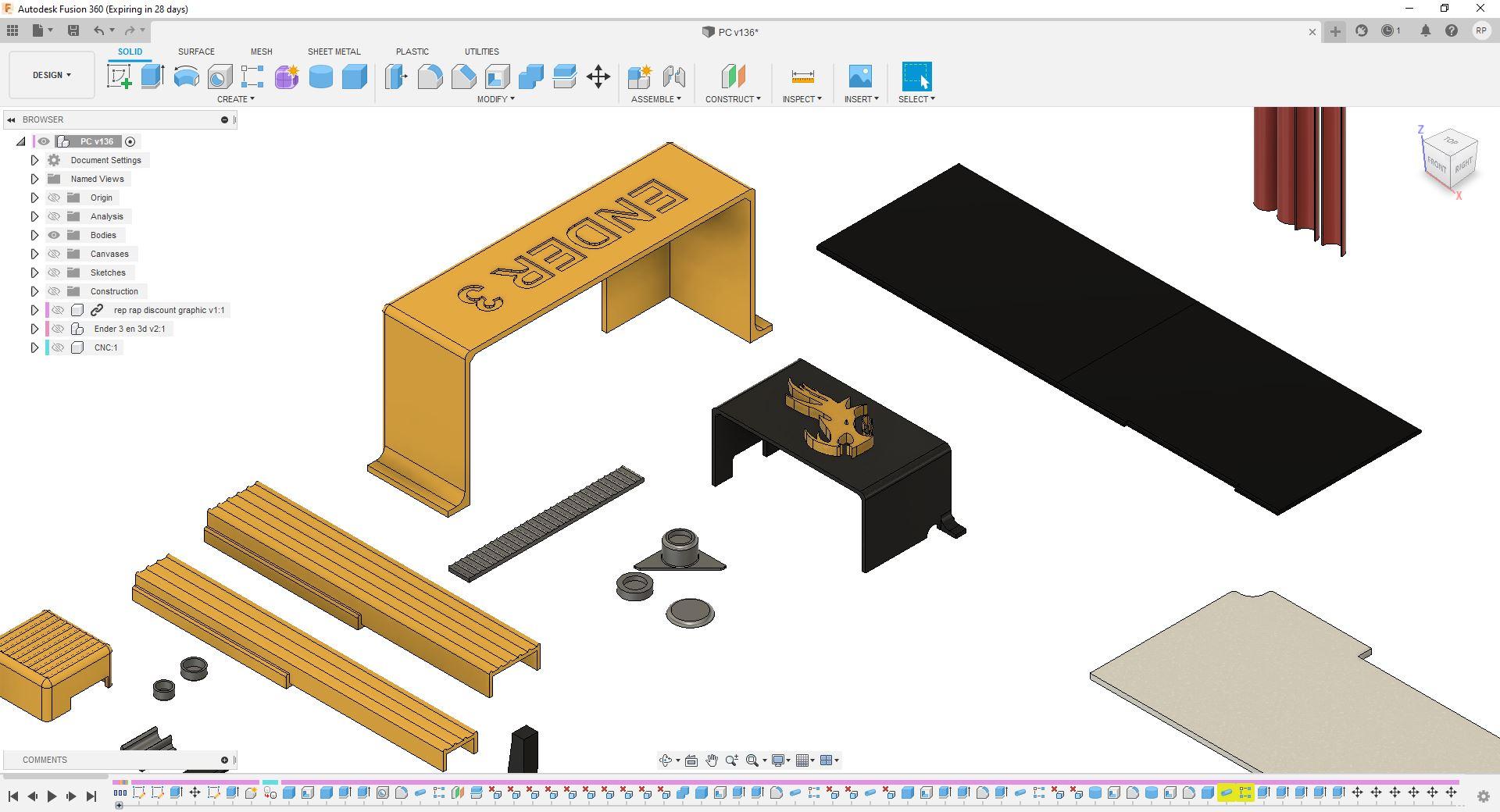
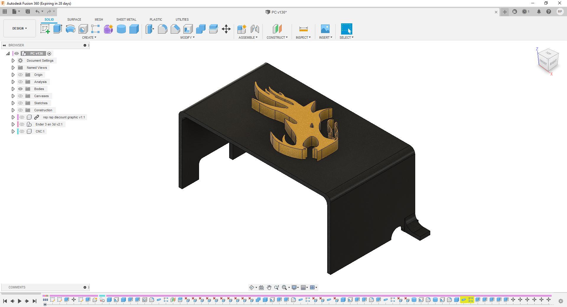
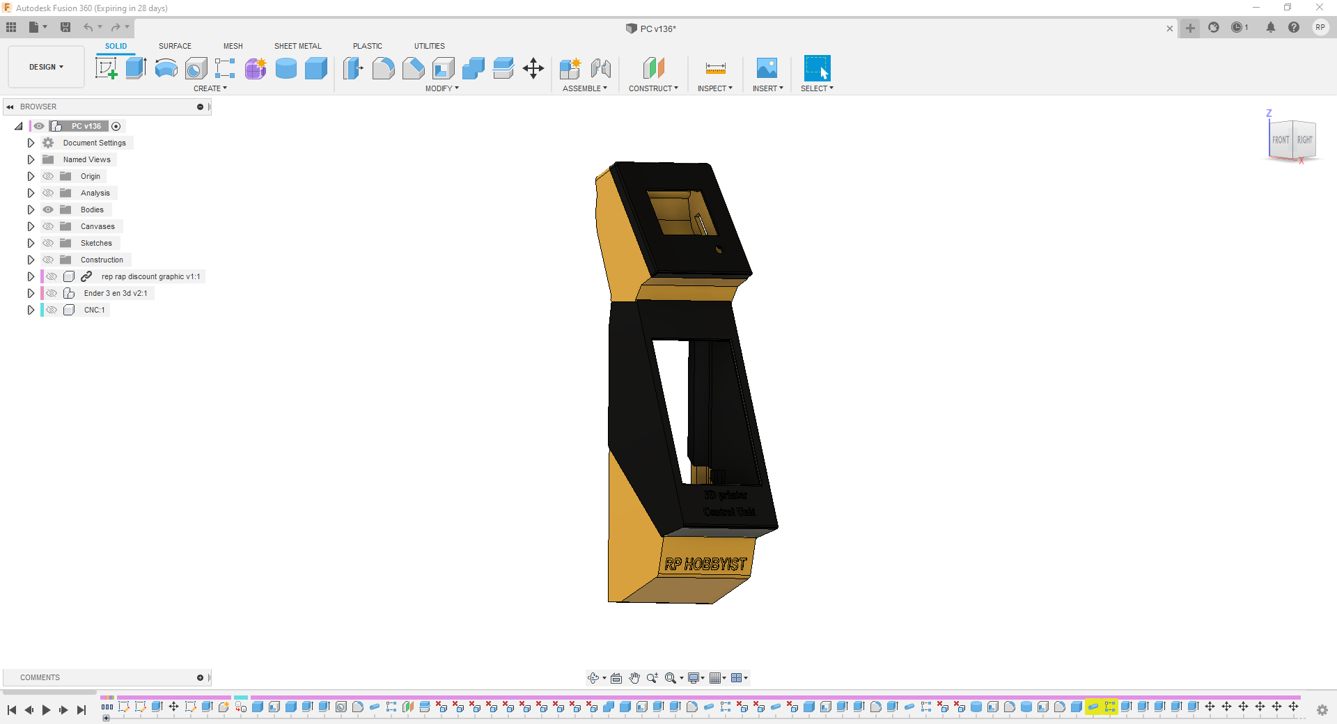
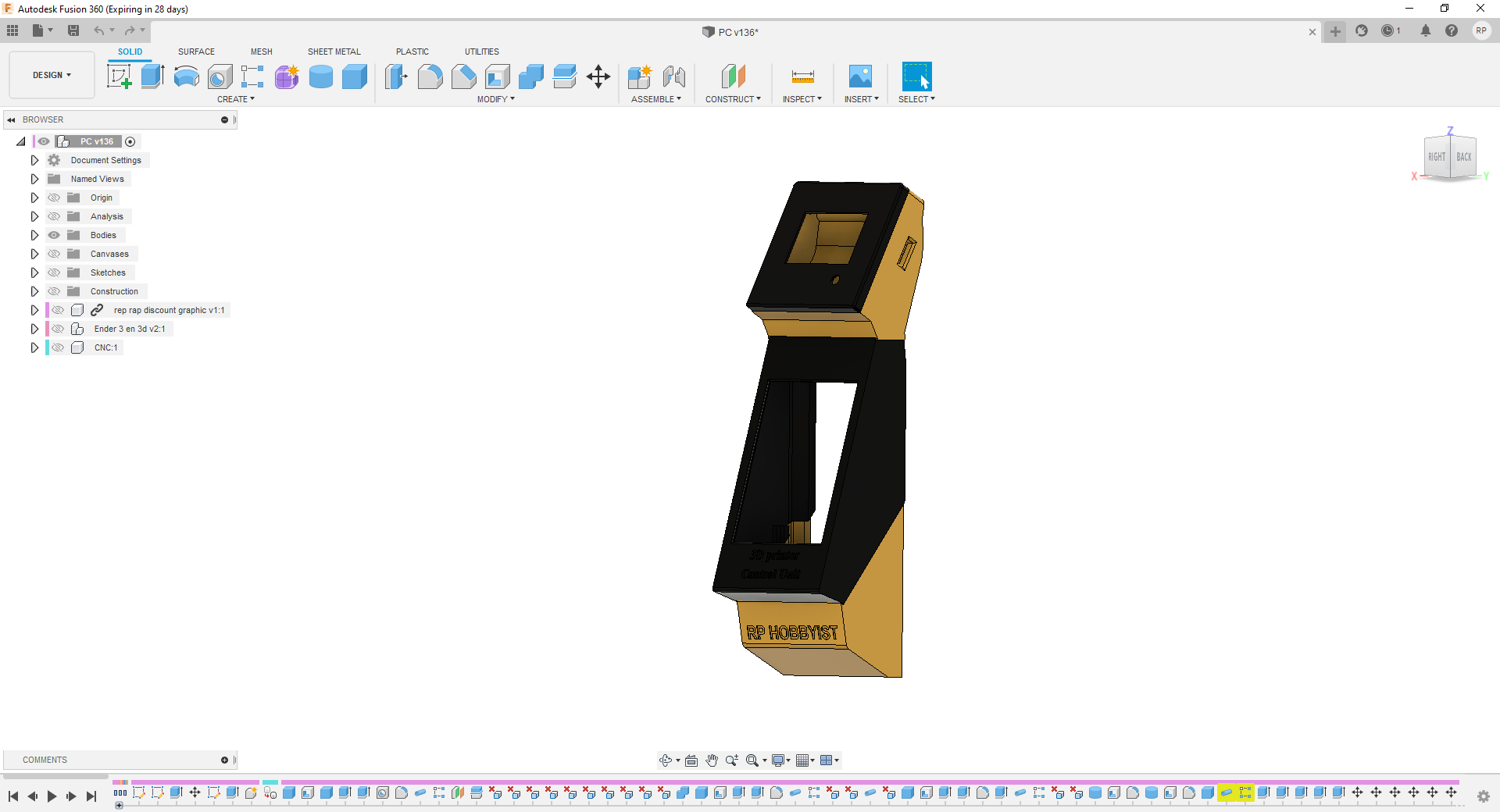
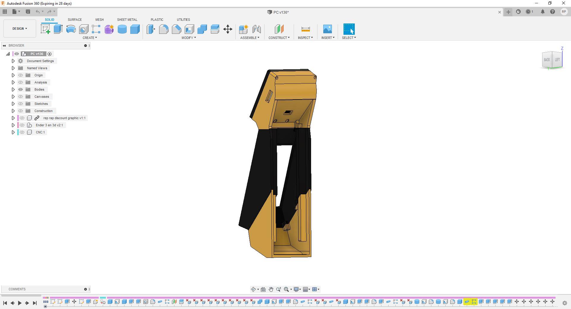
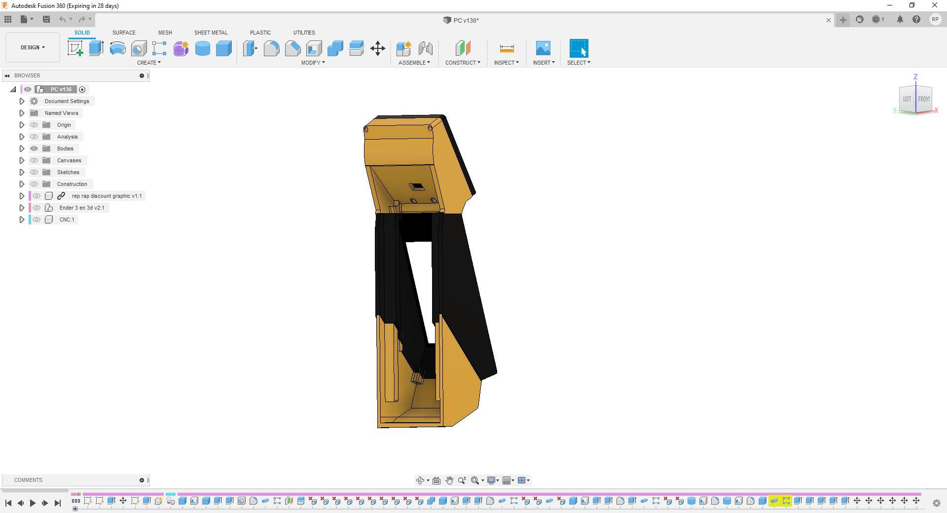
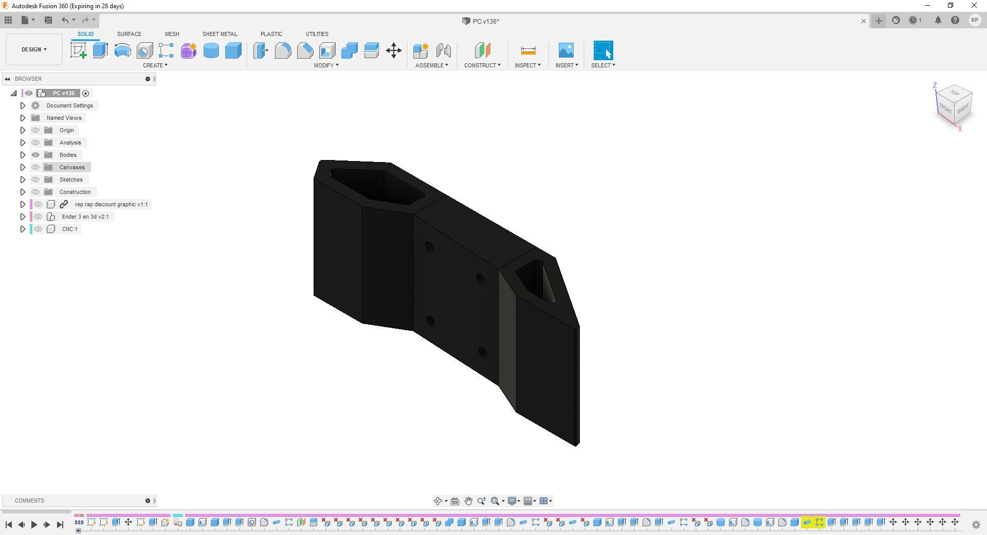
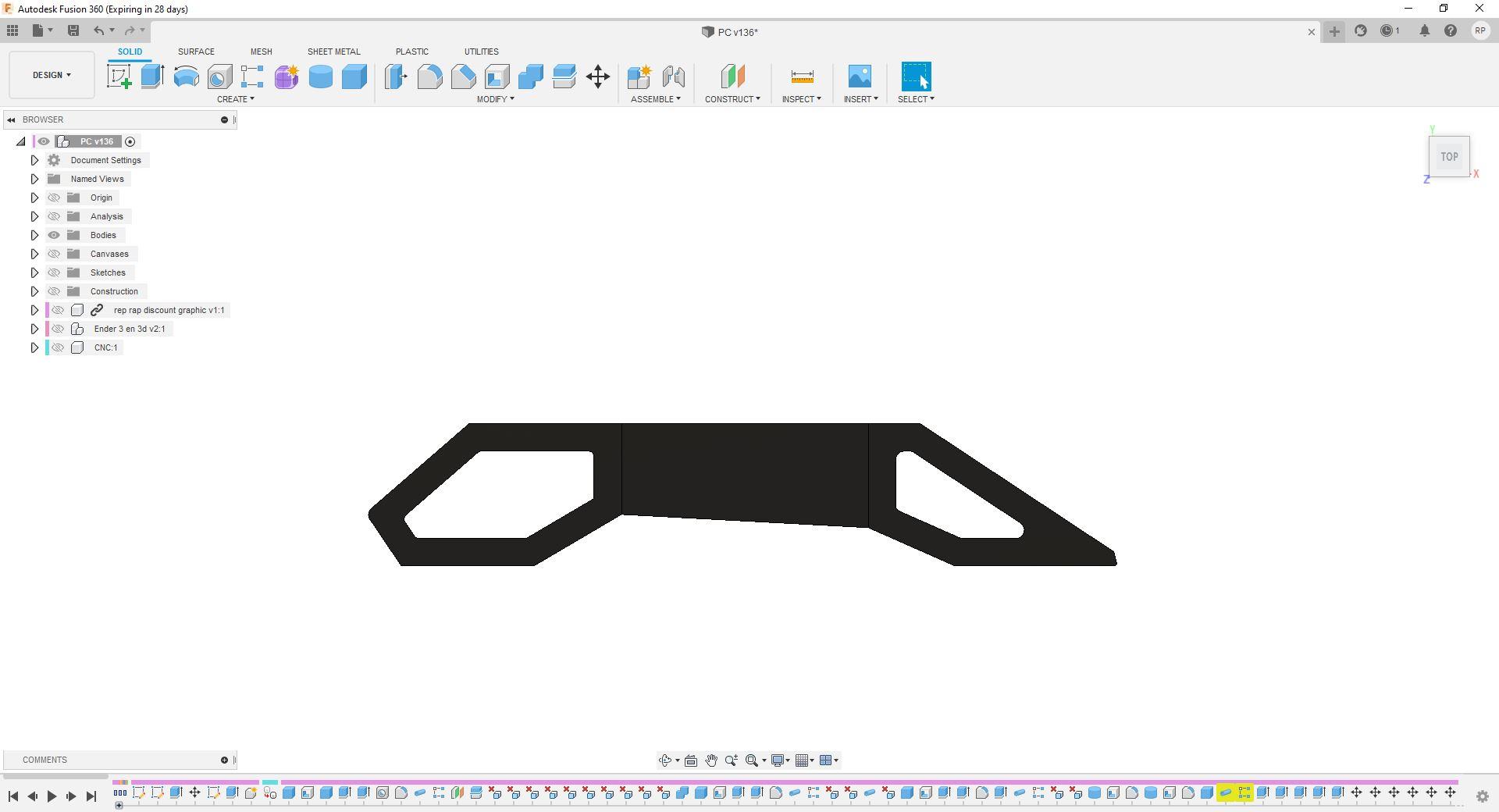
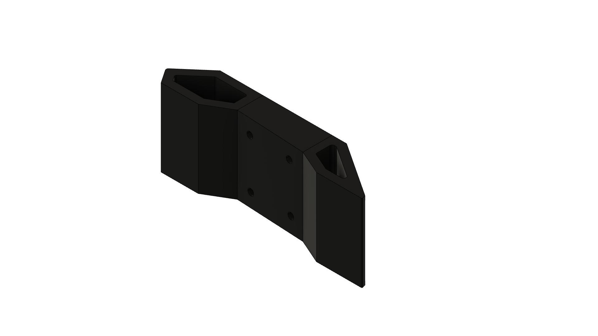
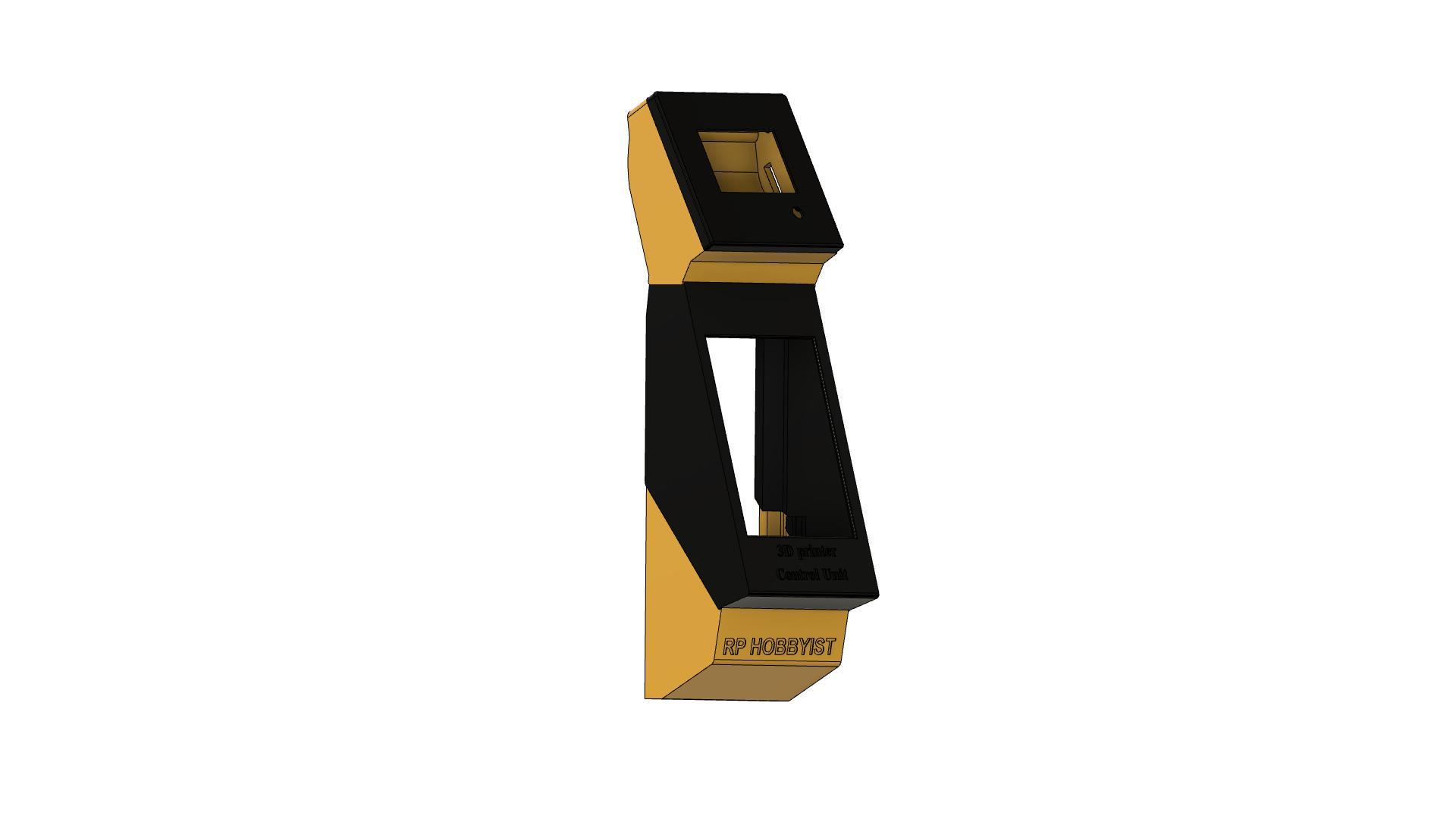
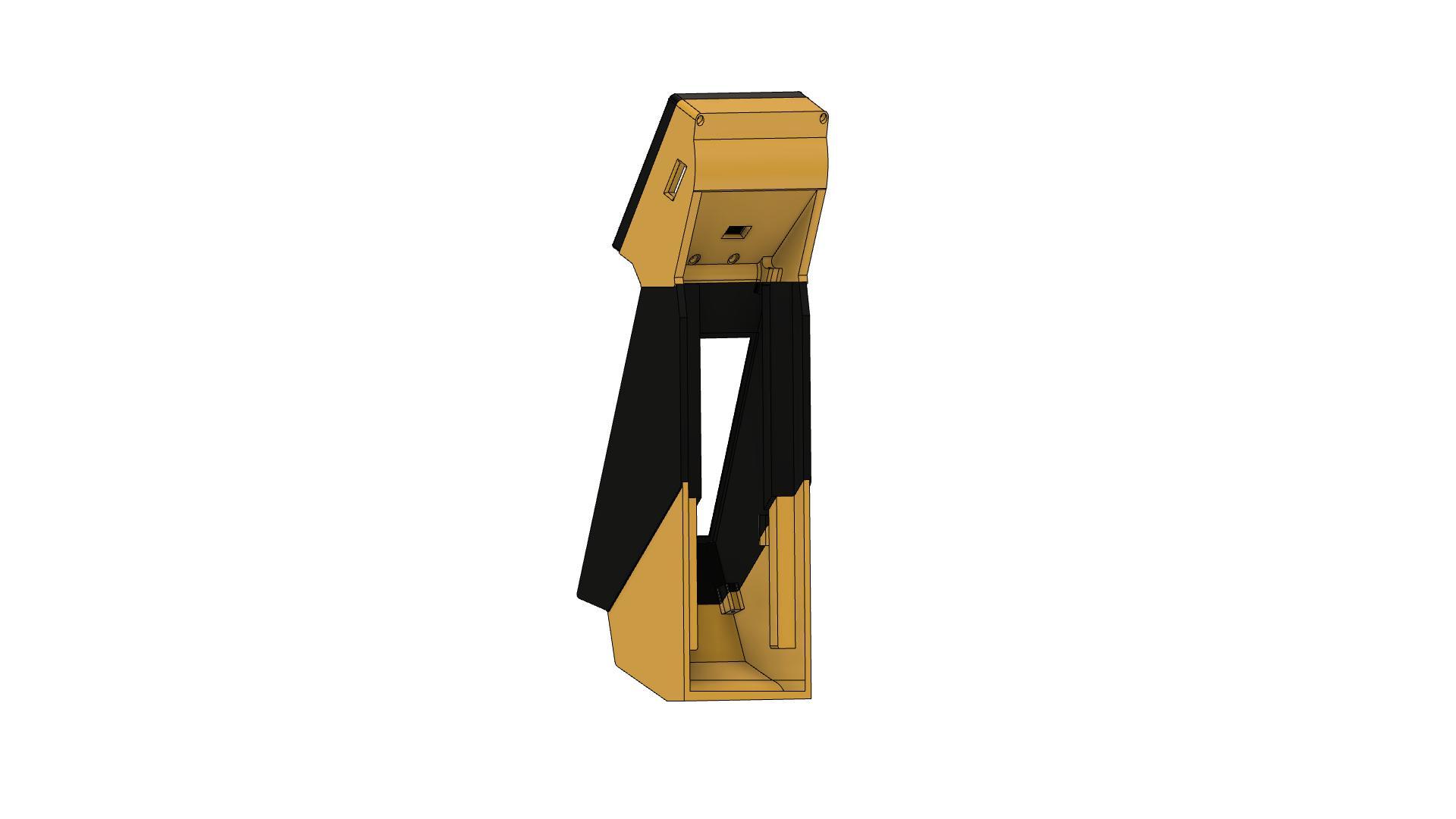
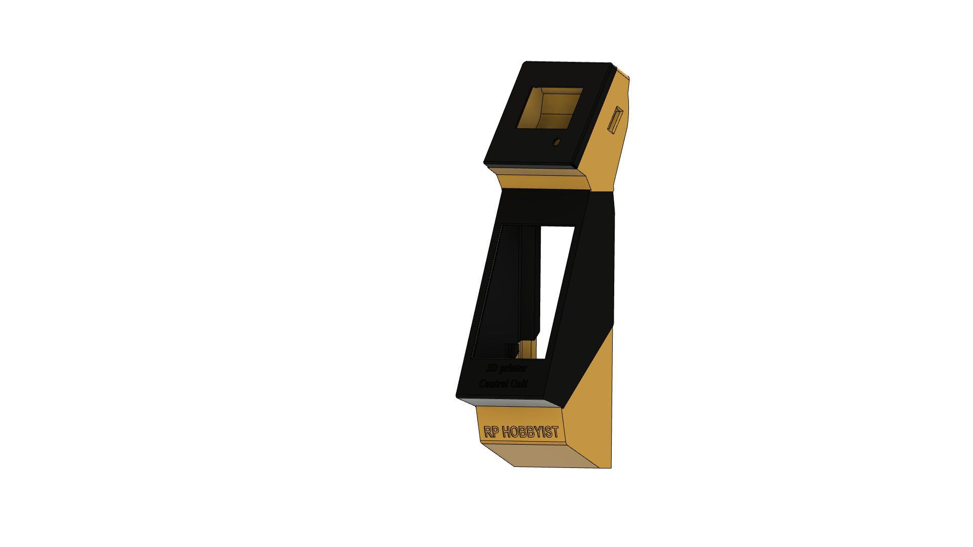
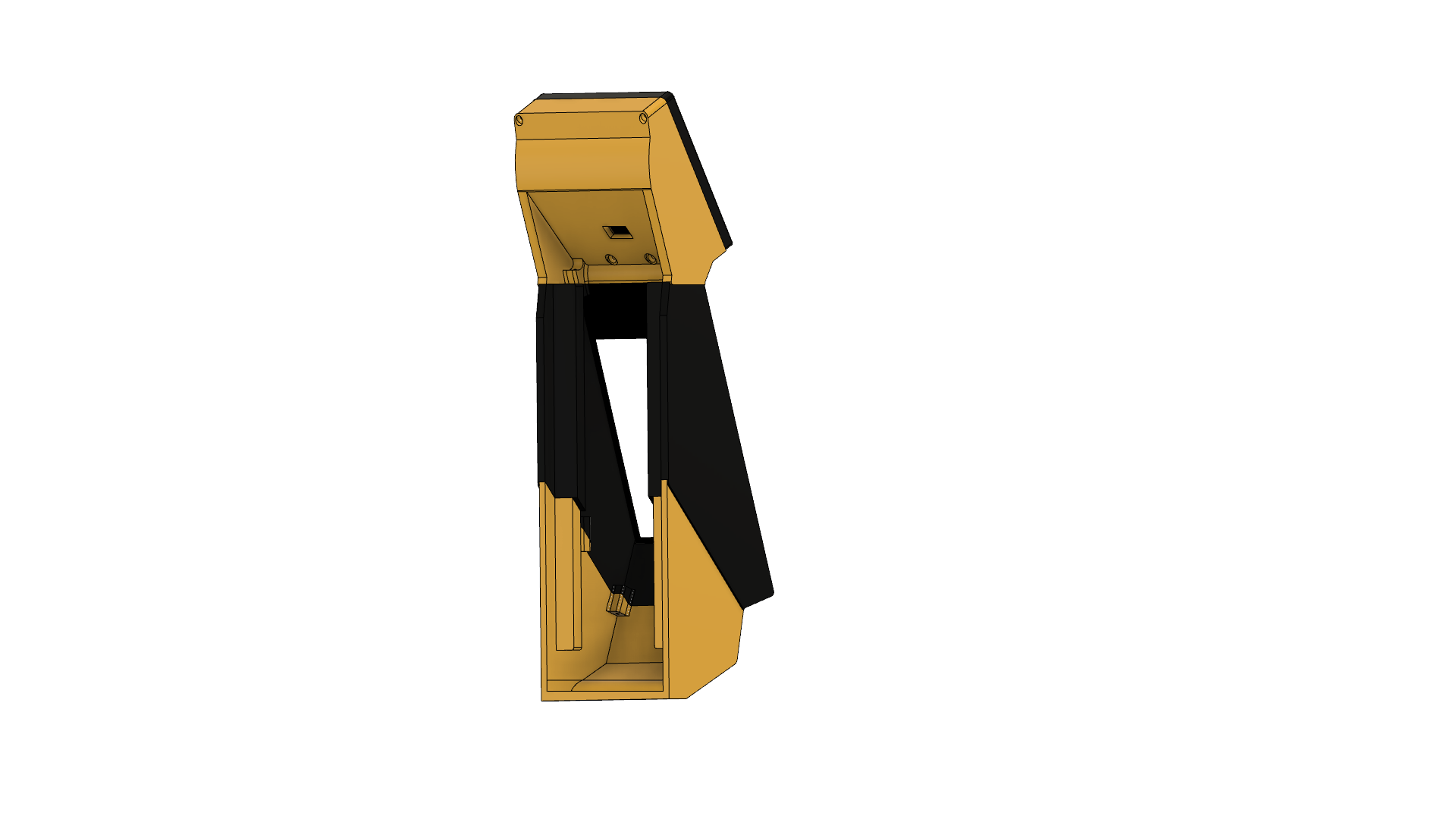
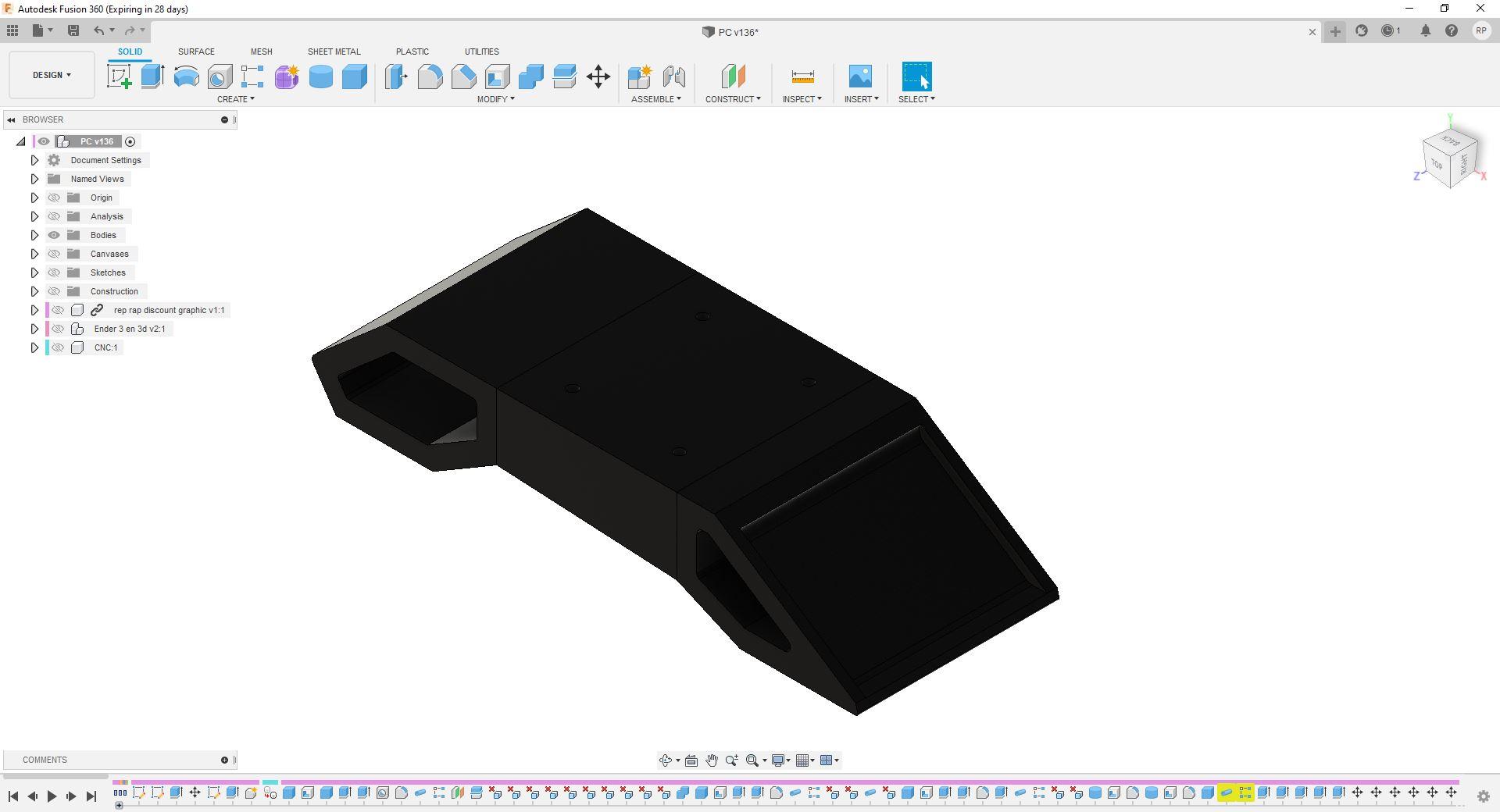
This took to 1 week to Design and Finalization. Designed in Fusion360 Software.
3D Printed Parts
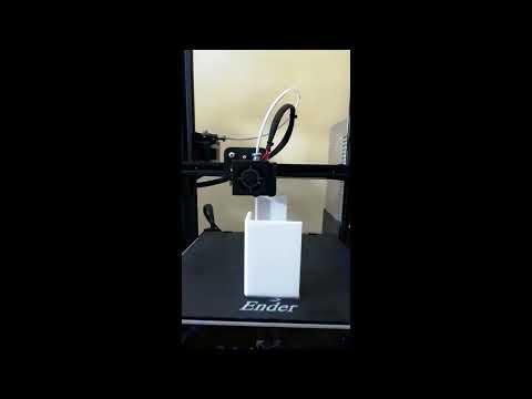
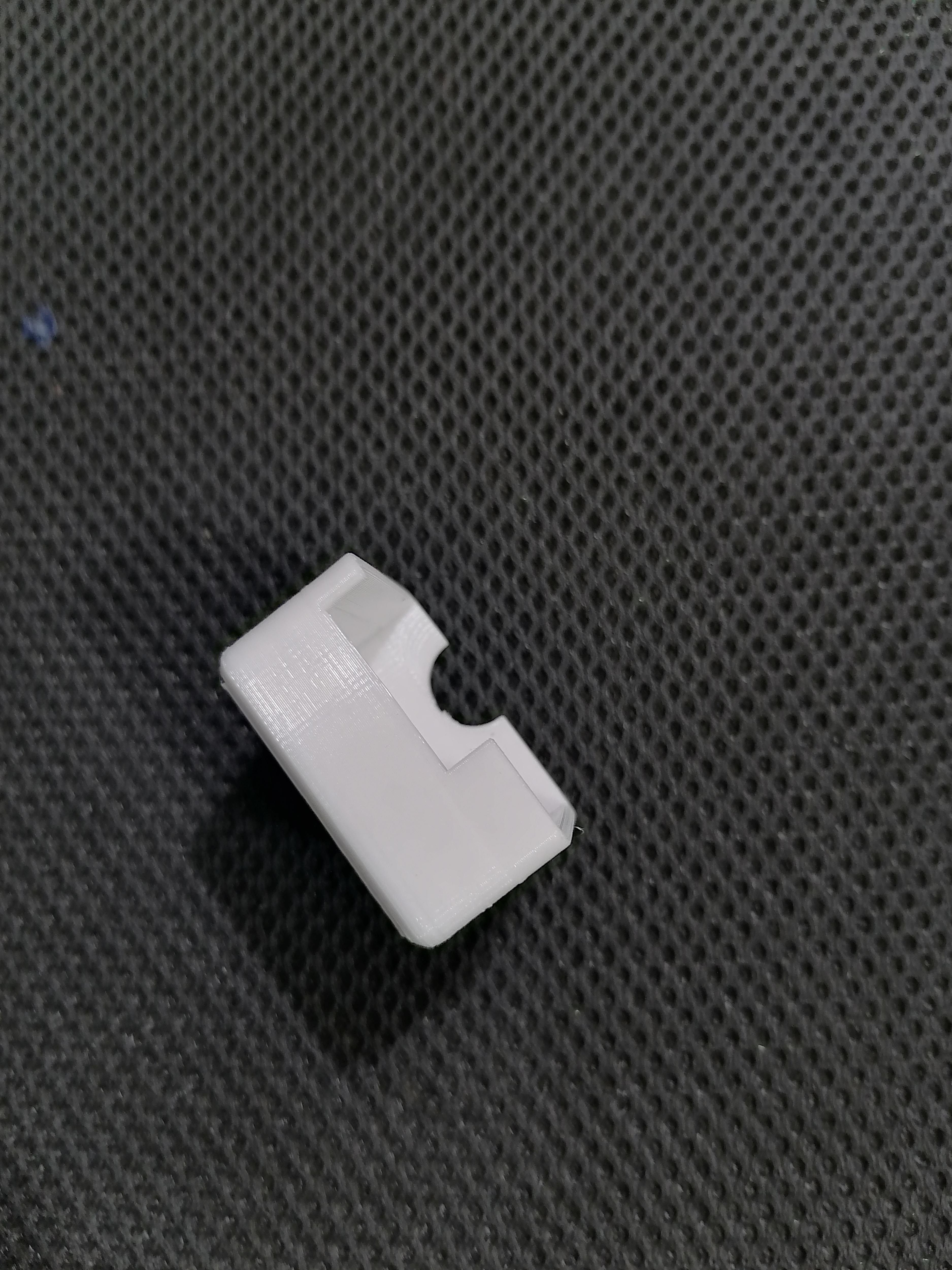


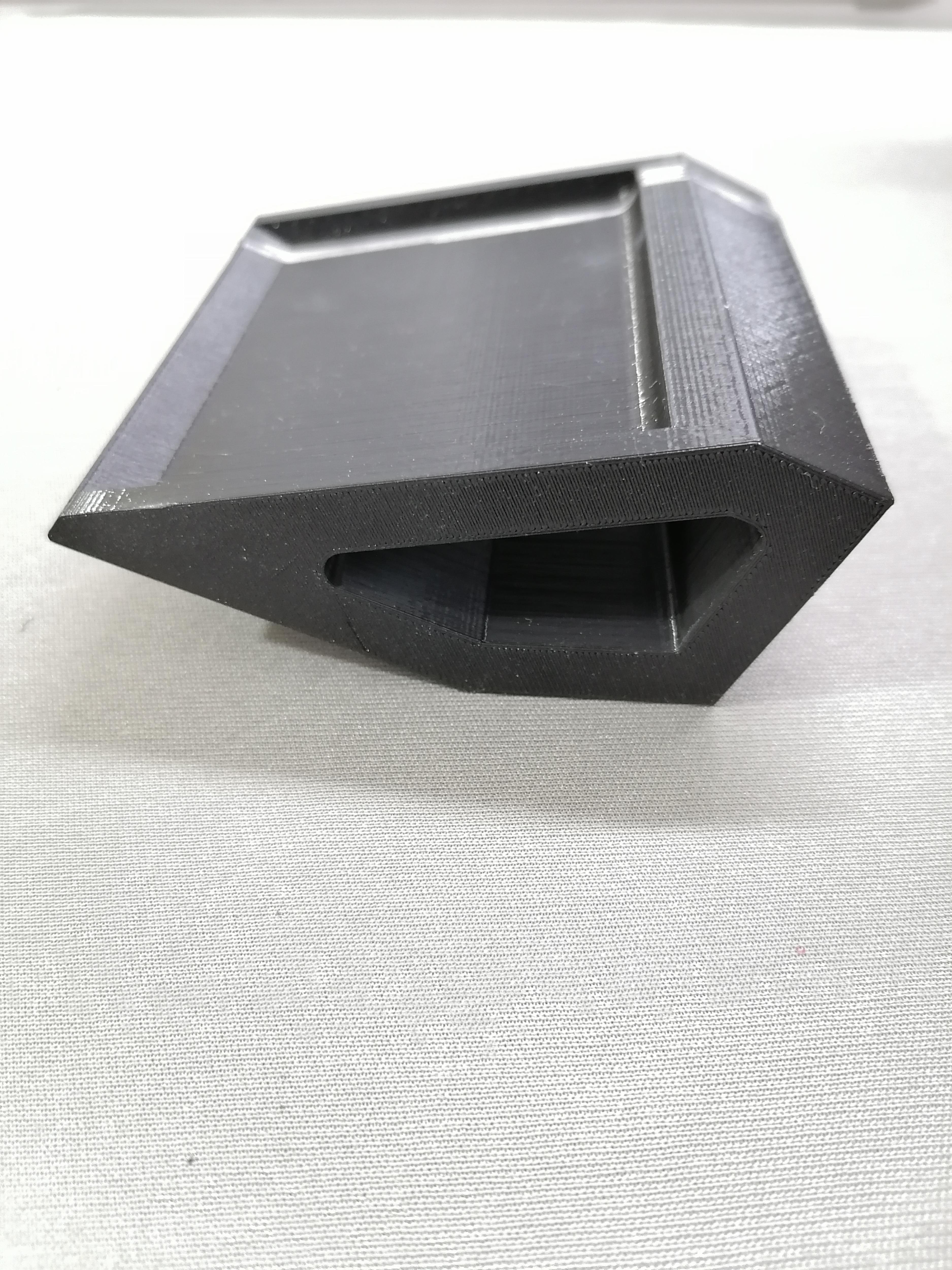

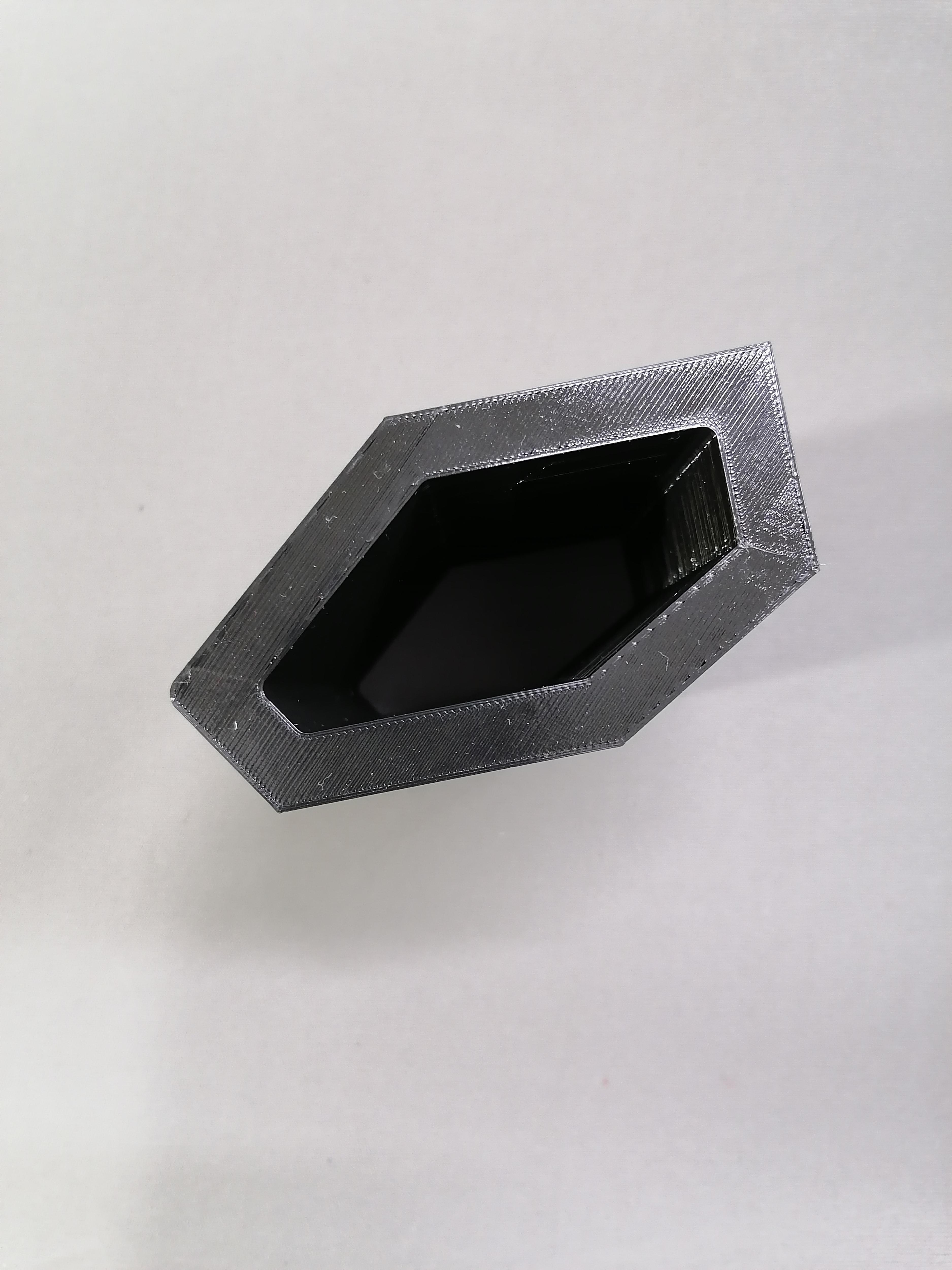

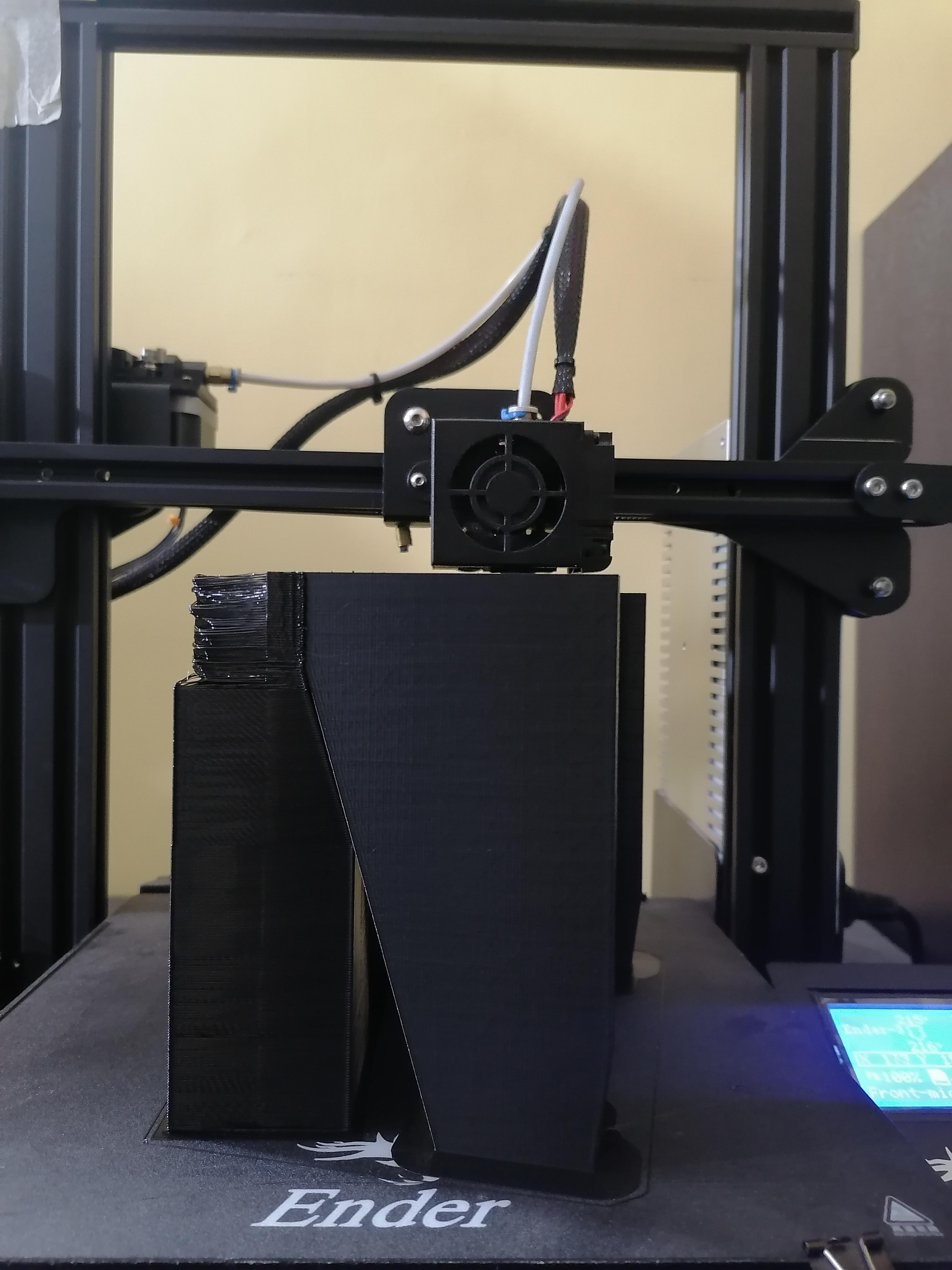
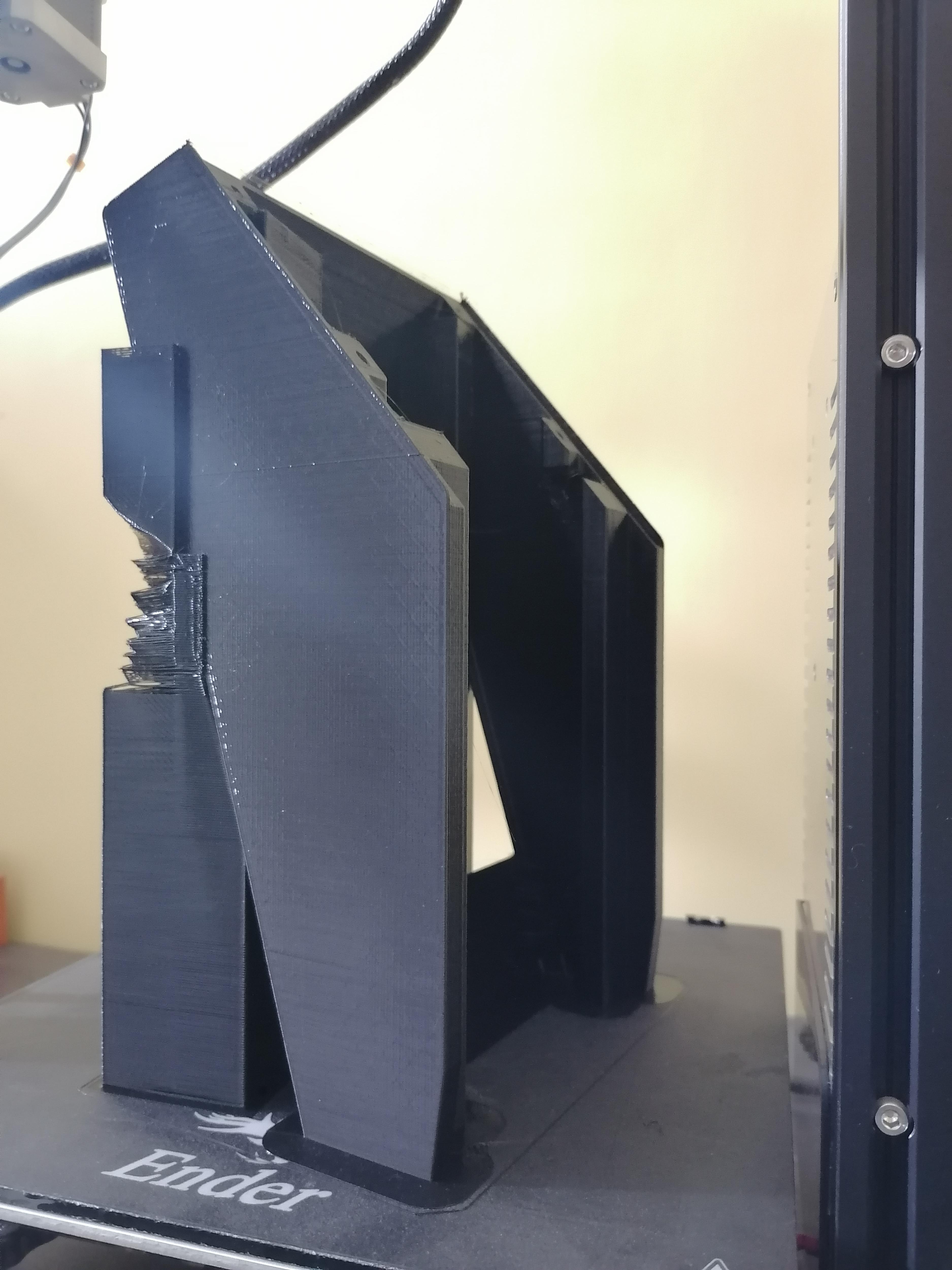
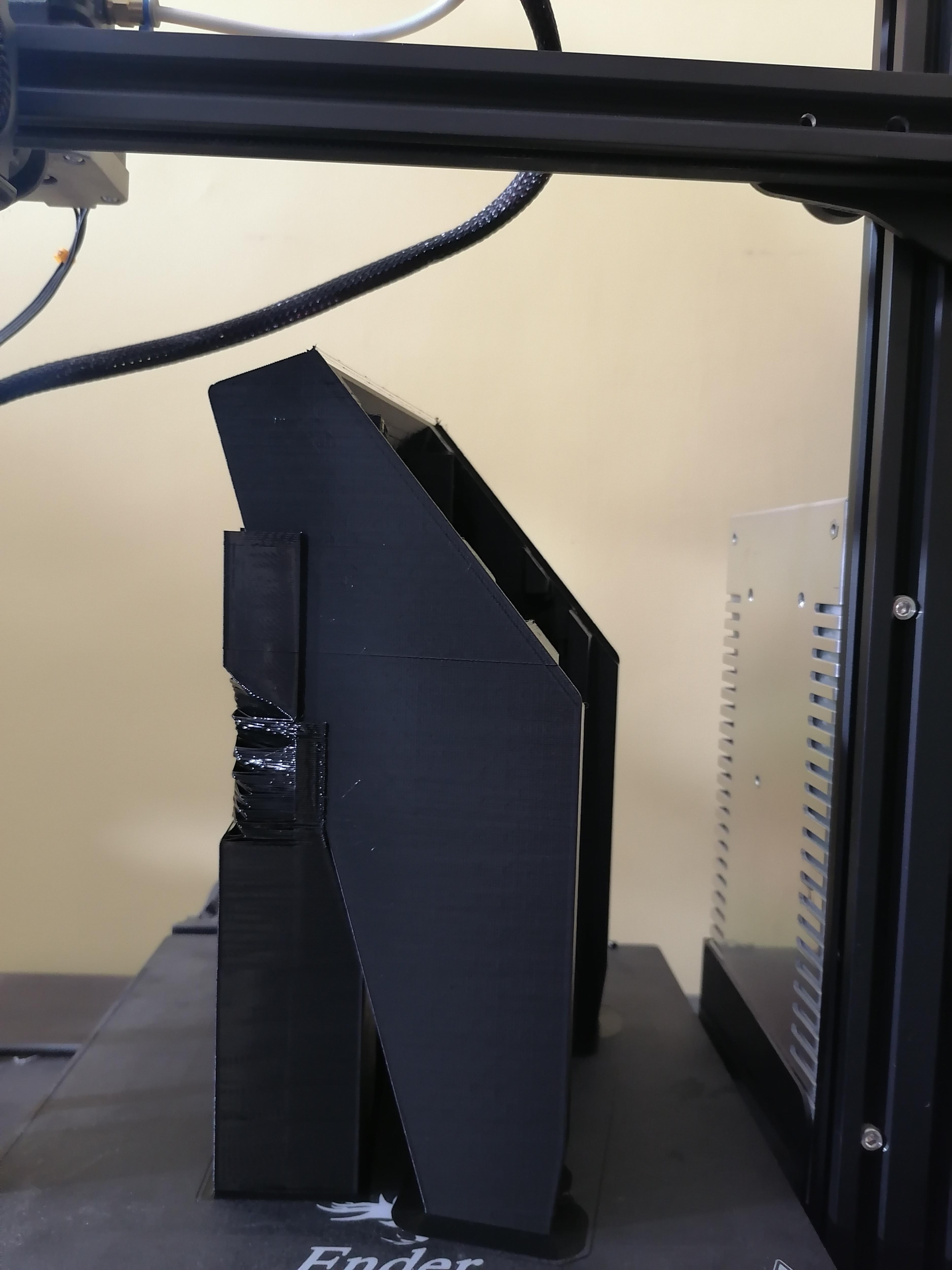

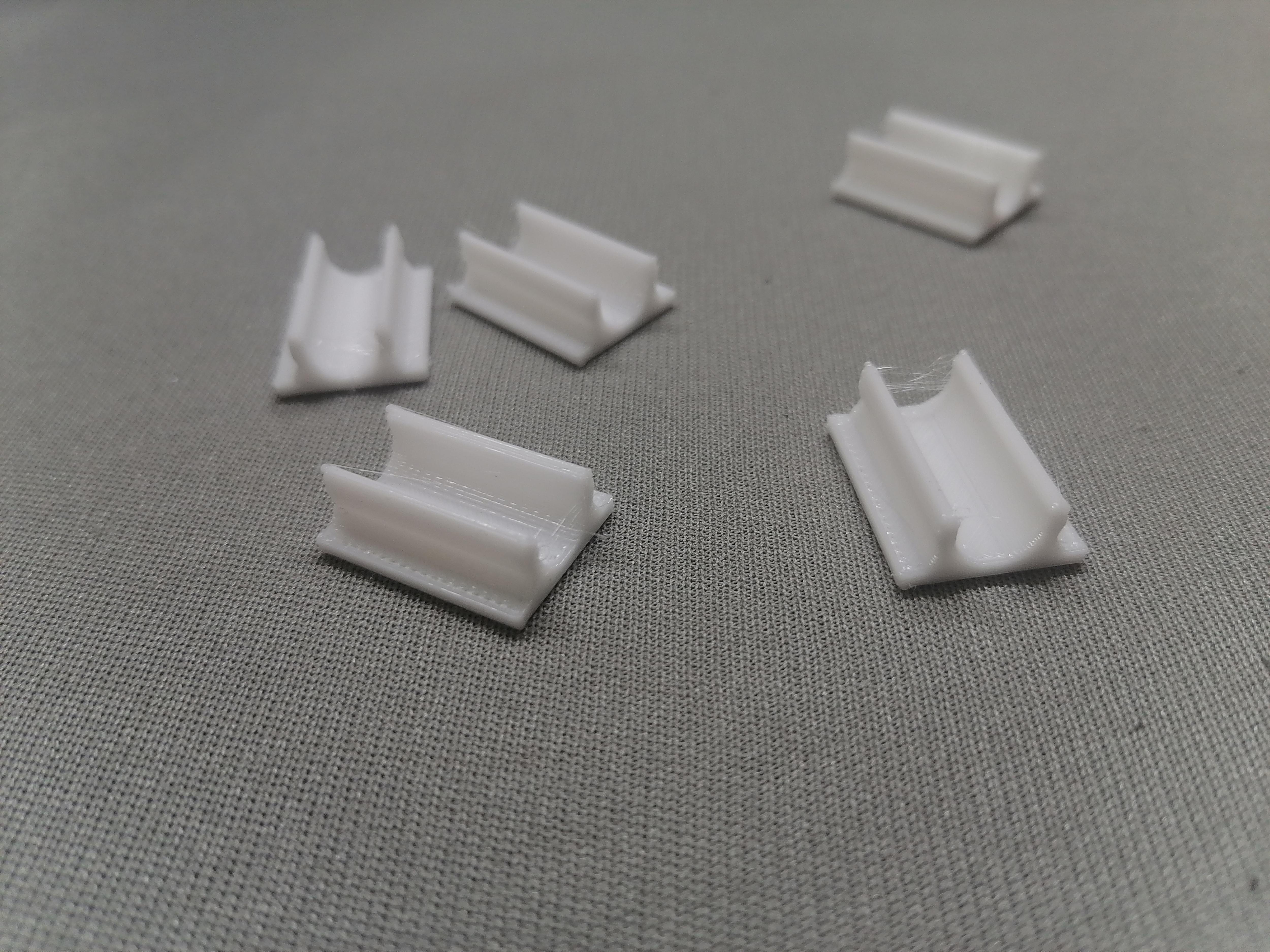
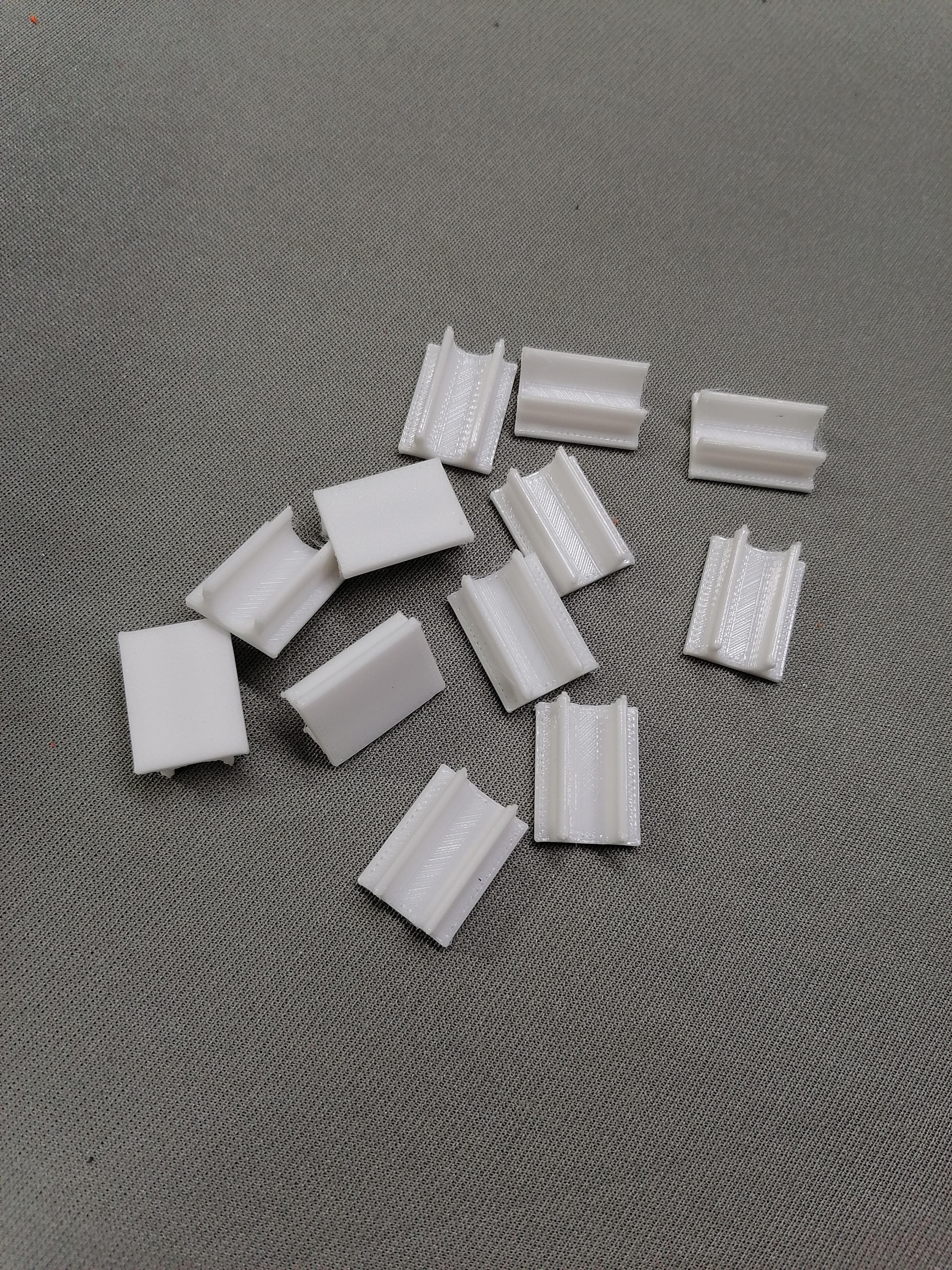
This took 3 to 4 Days to Print all parts.
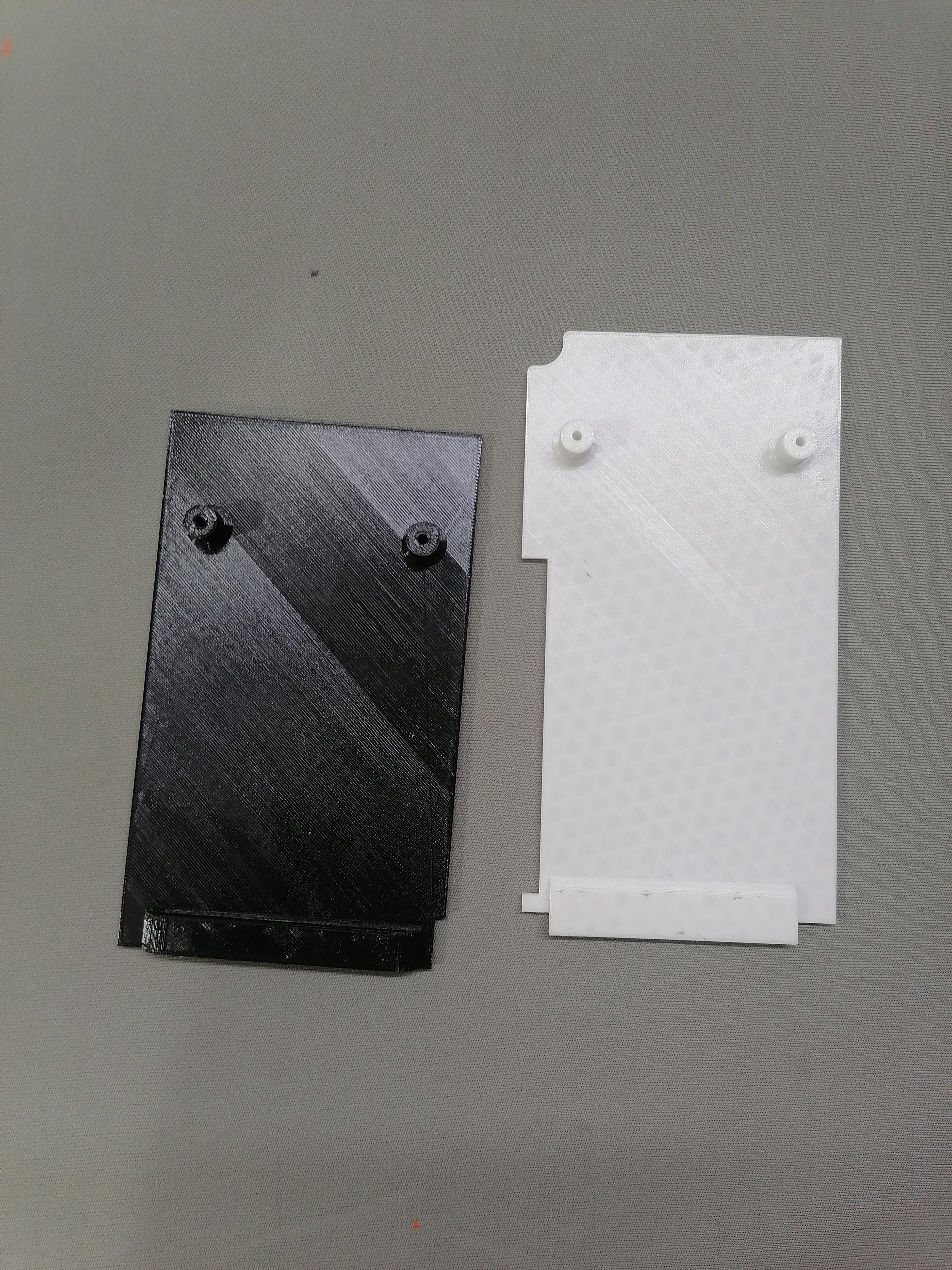
Download STL Files Print
Print all 38 parts.
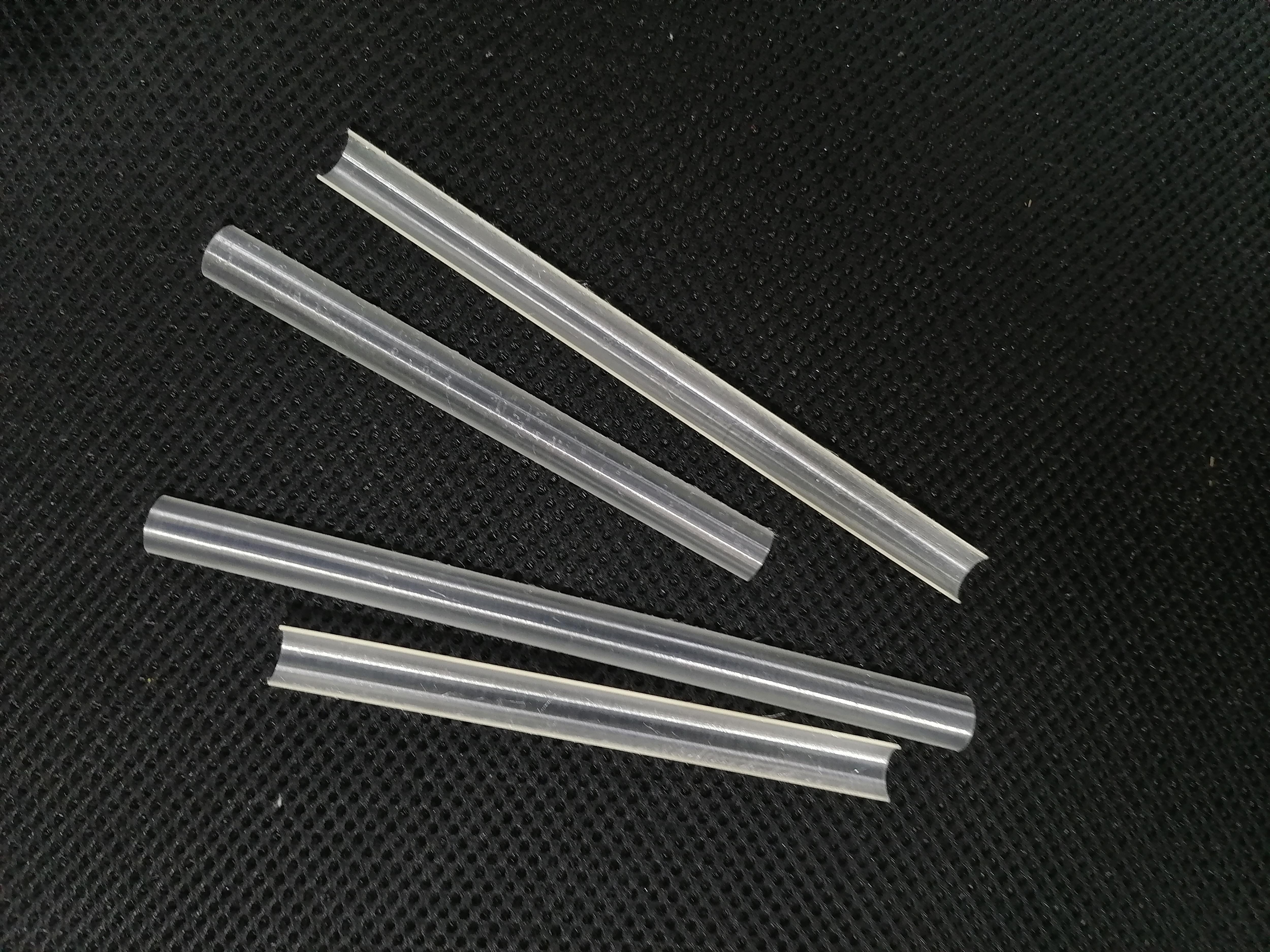
Note1: LED diffuser is printed on transparent PLA Filament. Need to have Brim support. 100% infill.
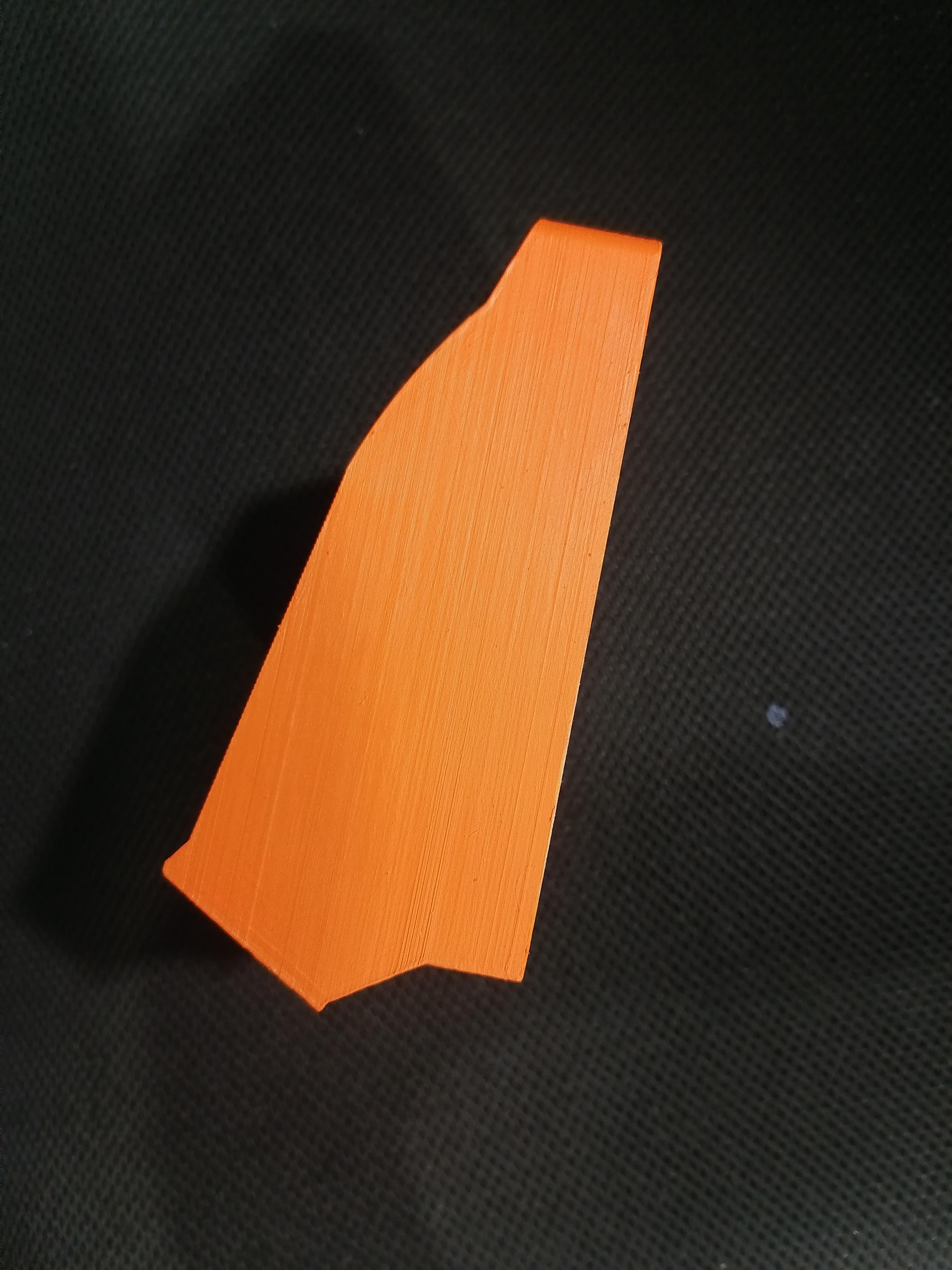
Note2: Front-middle-1 needs support.
Downloads
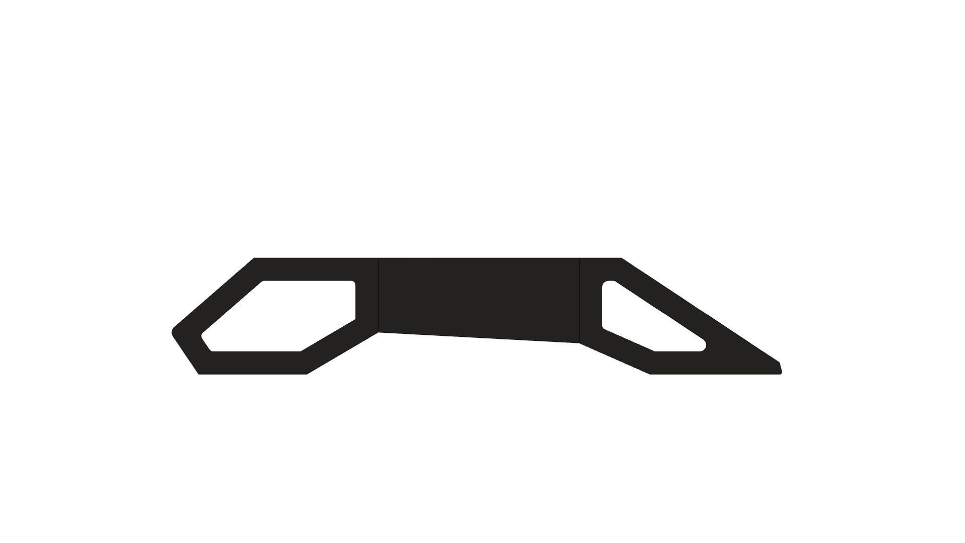
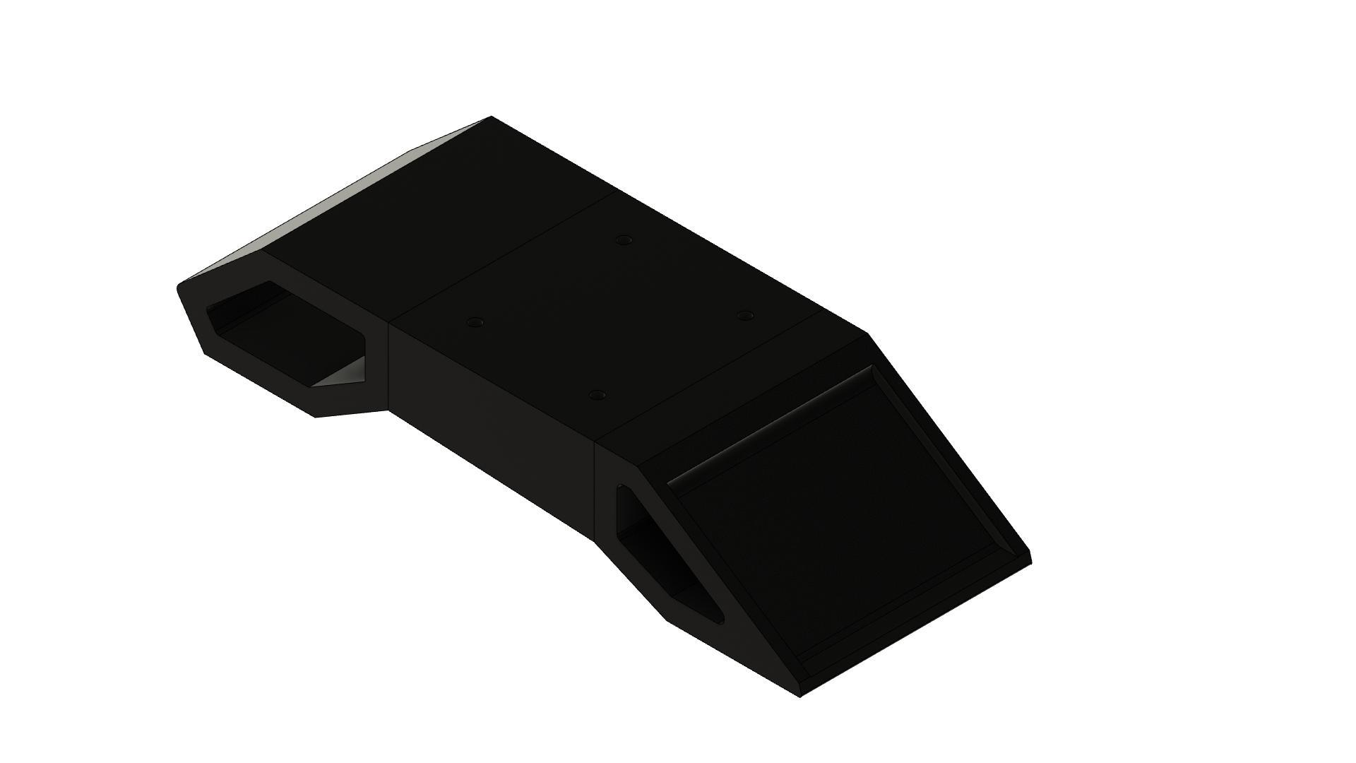
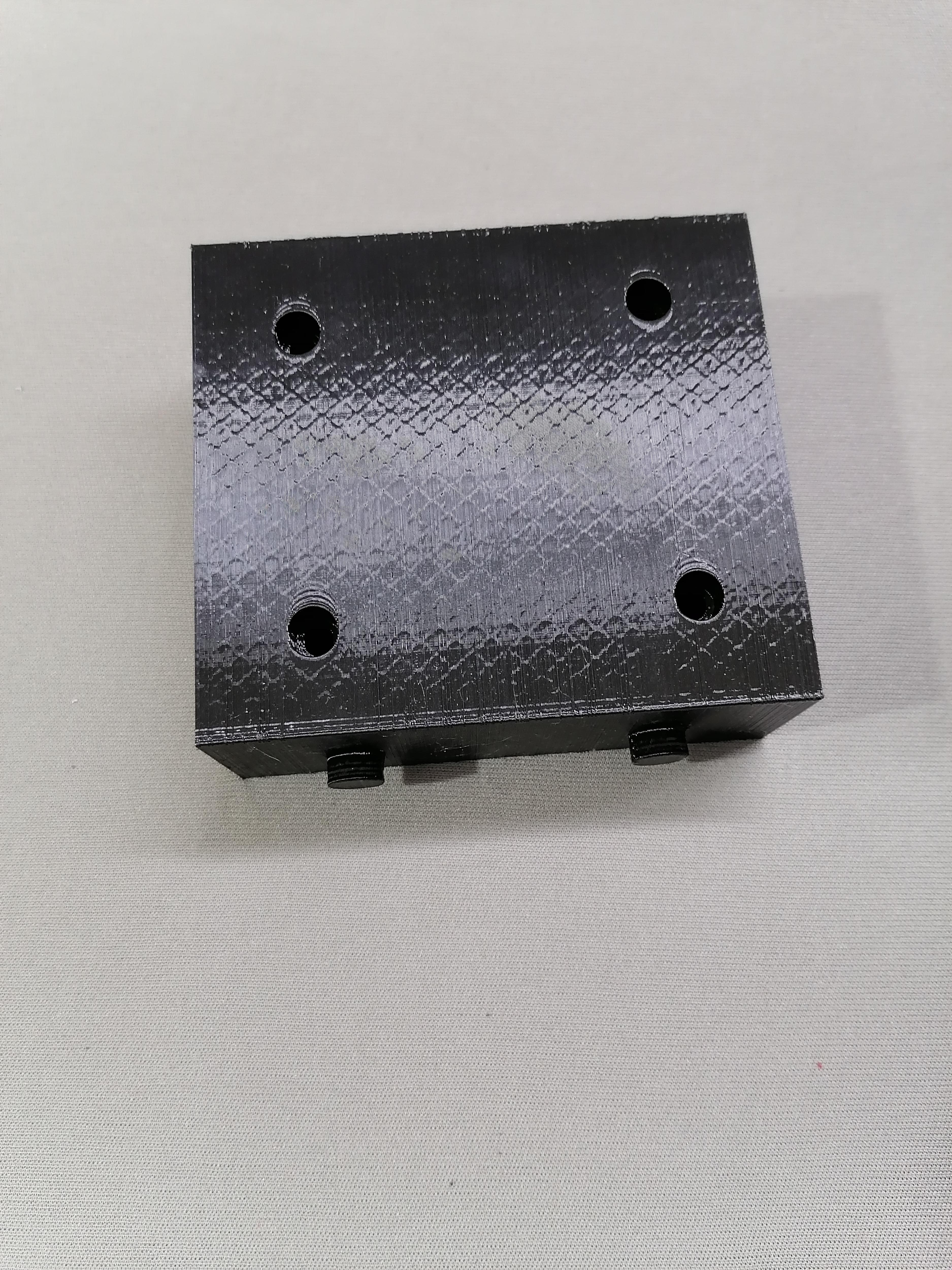
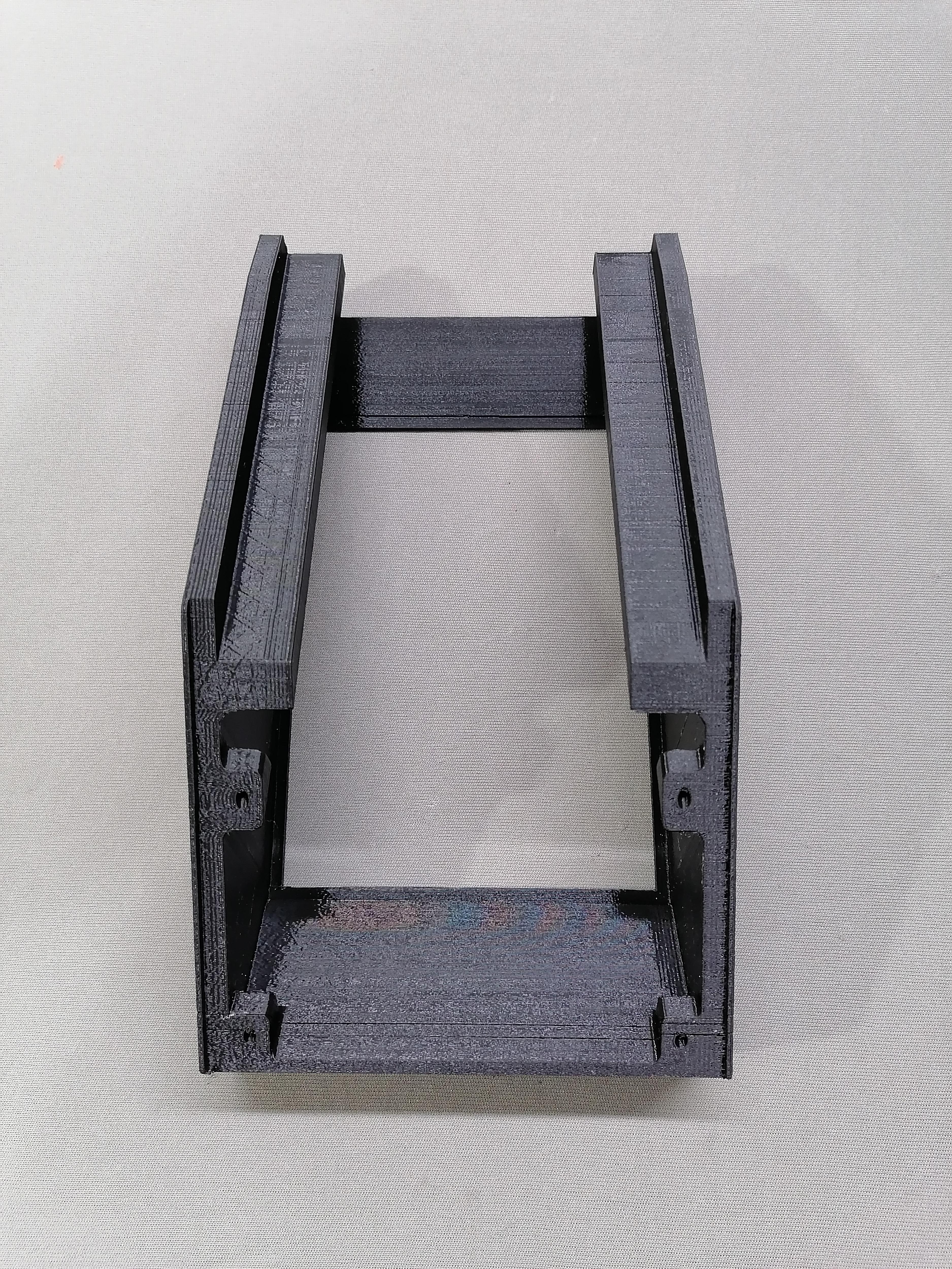
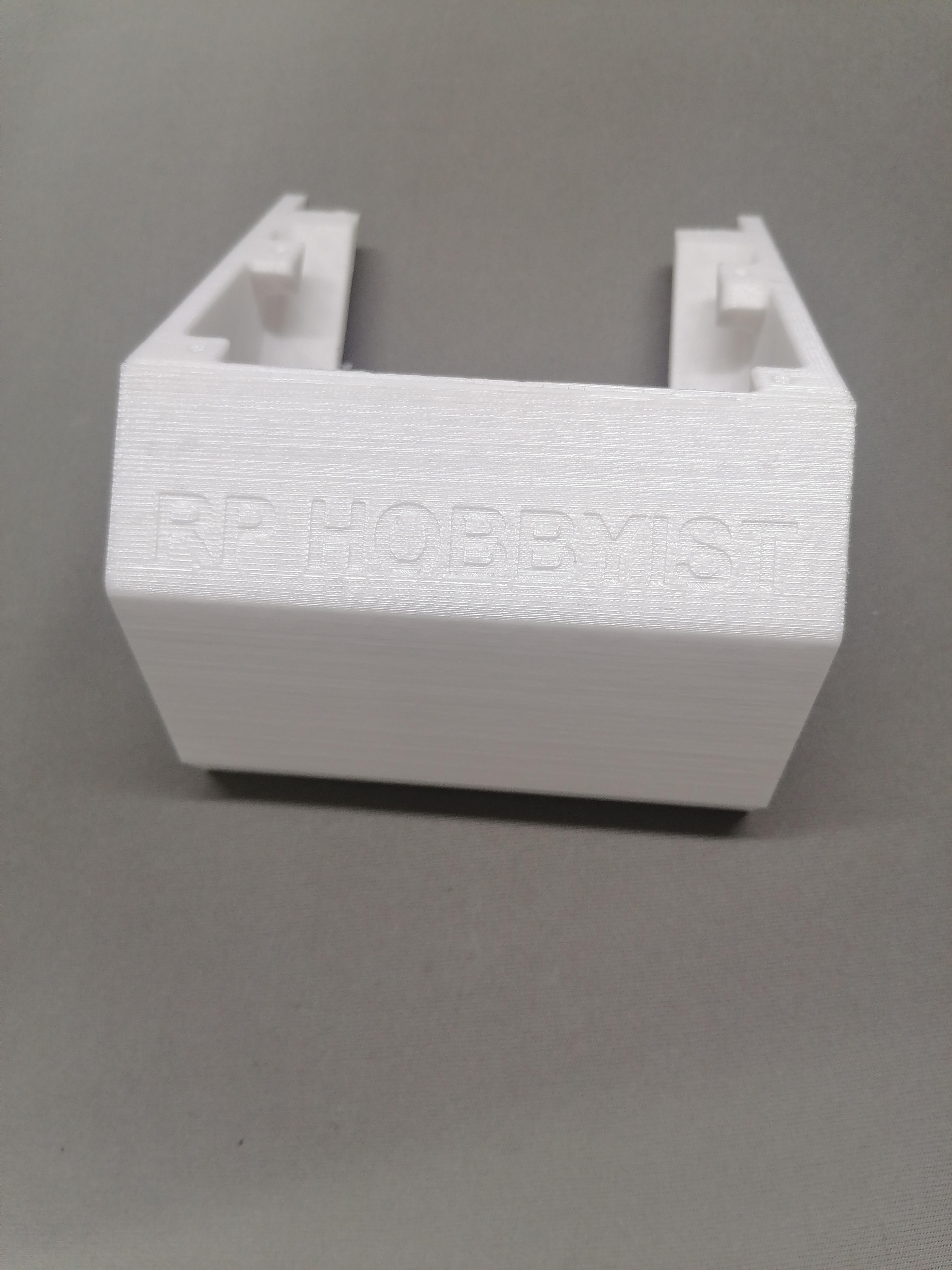
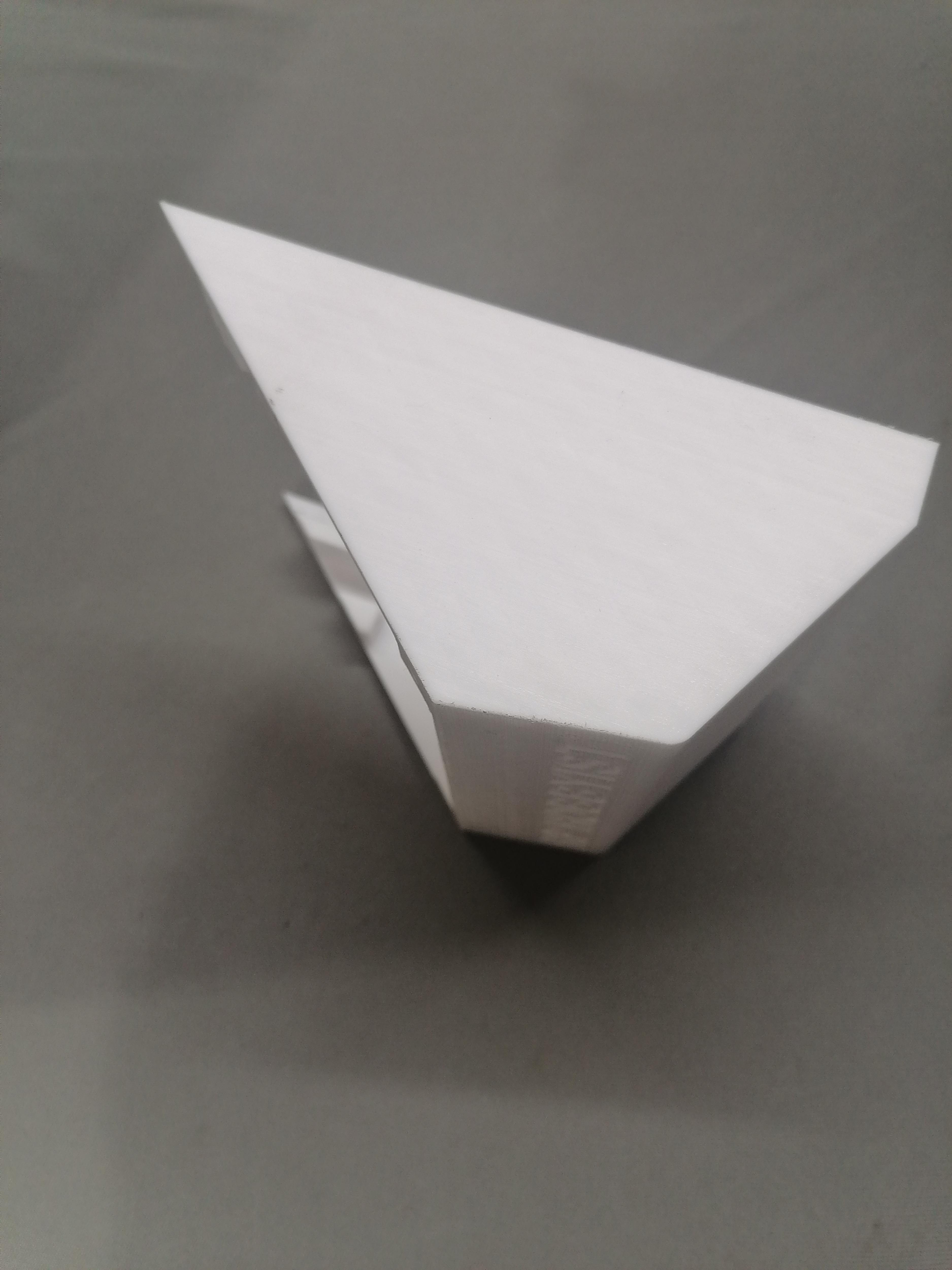
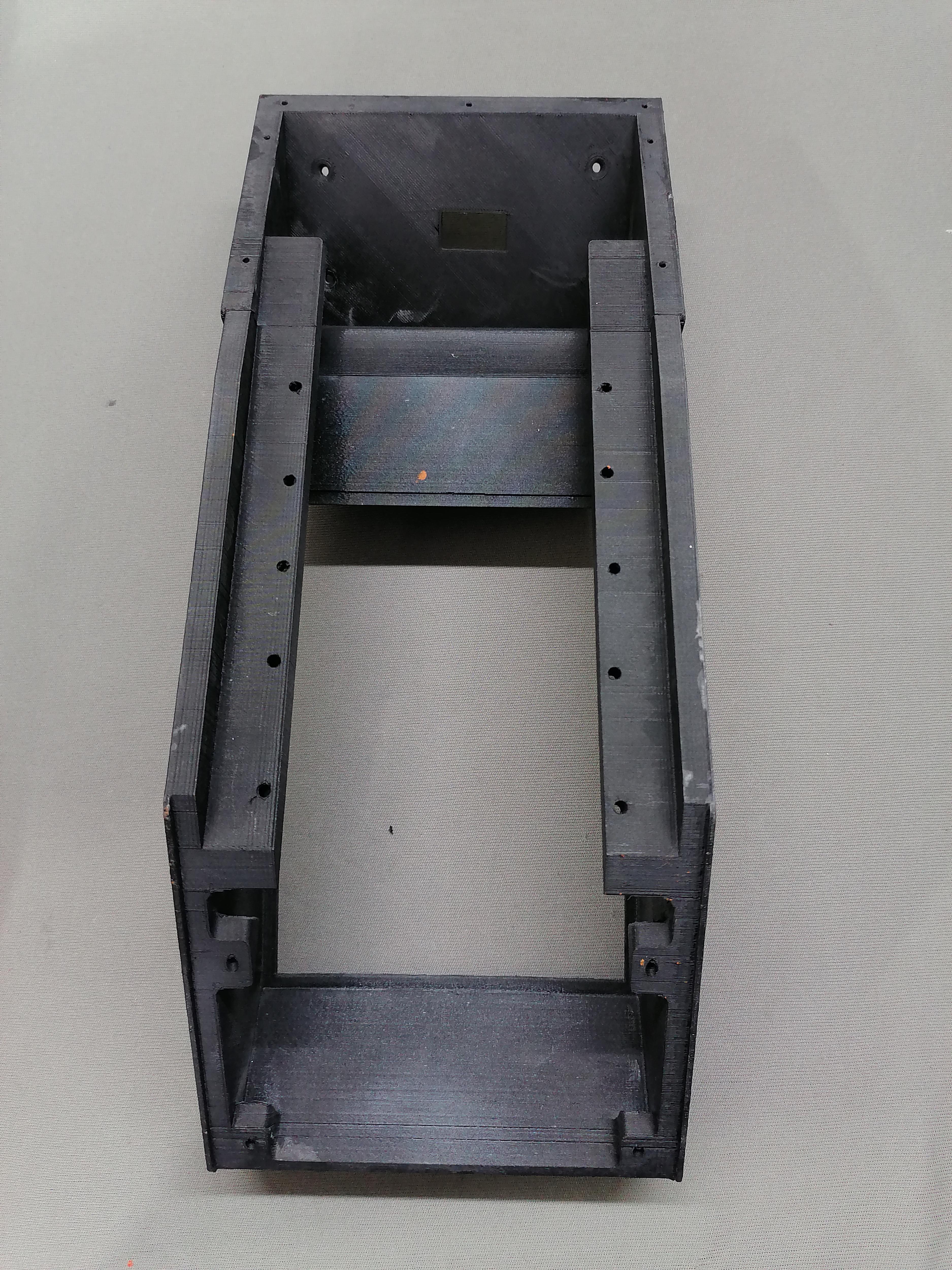
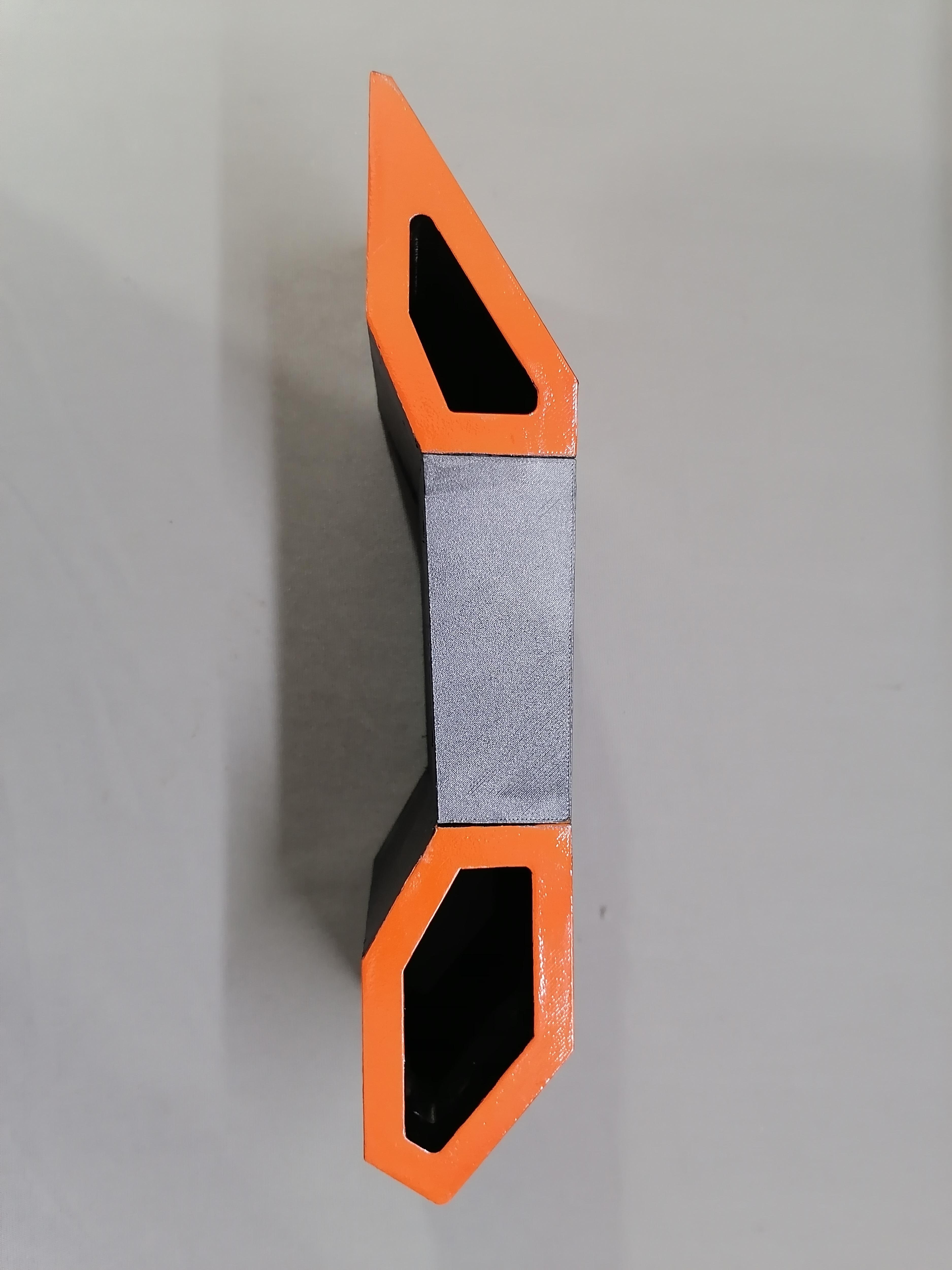
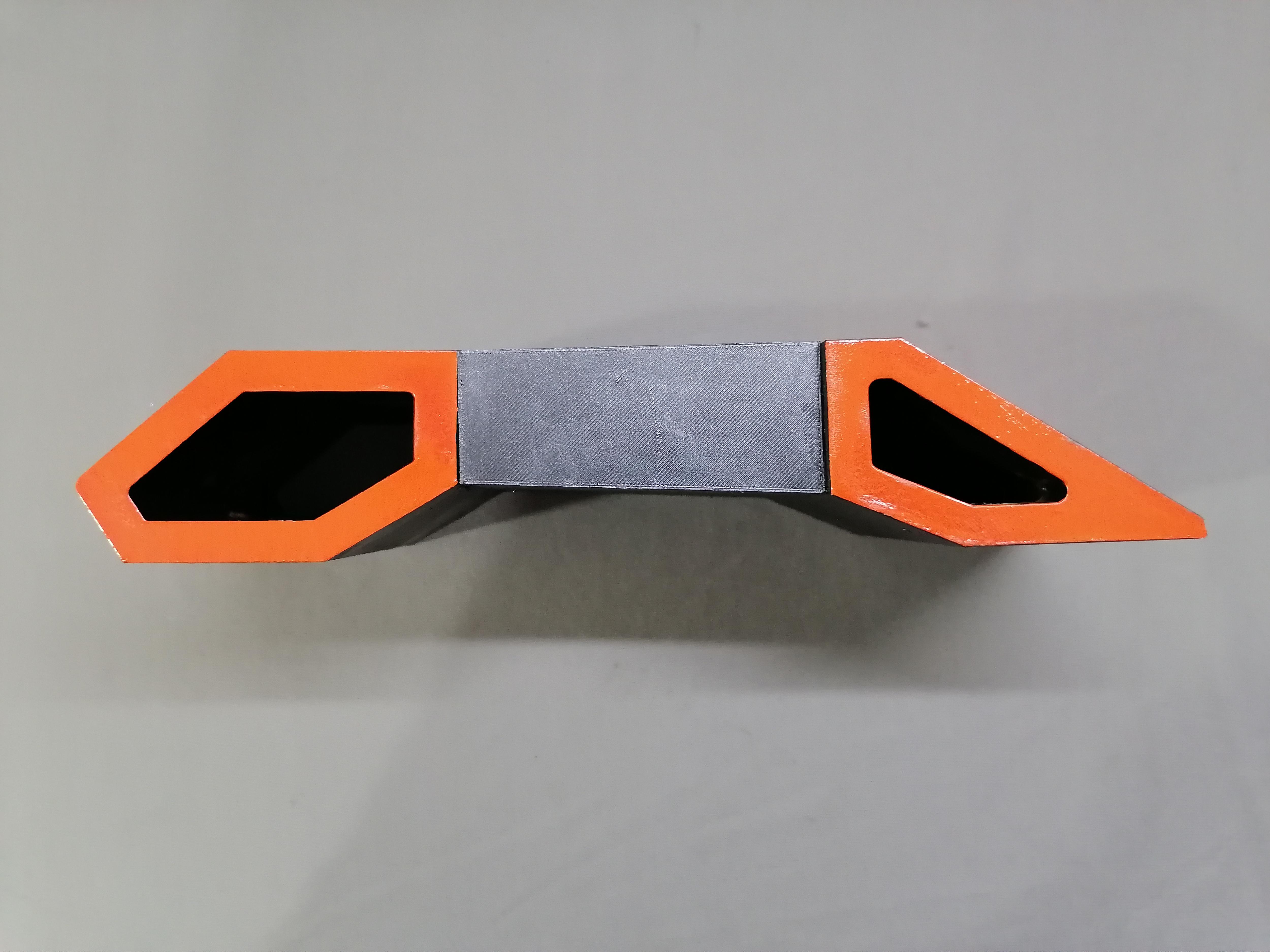
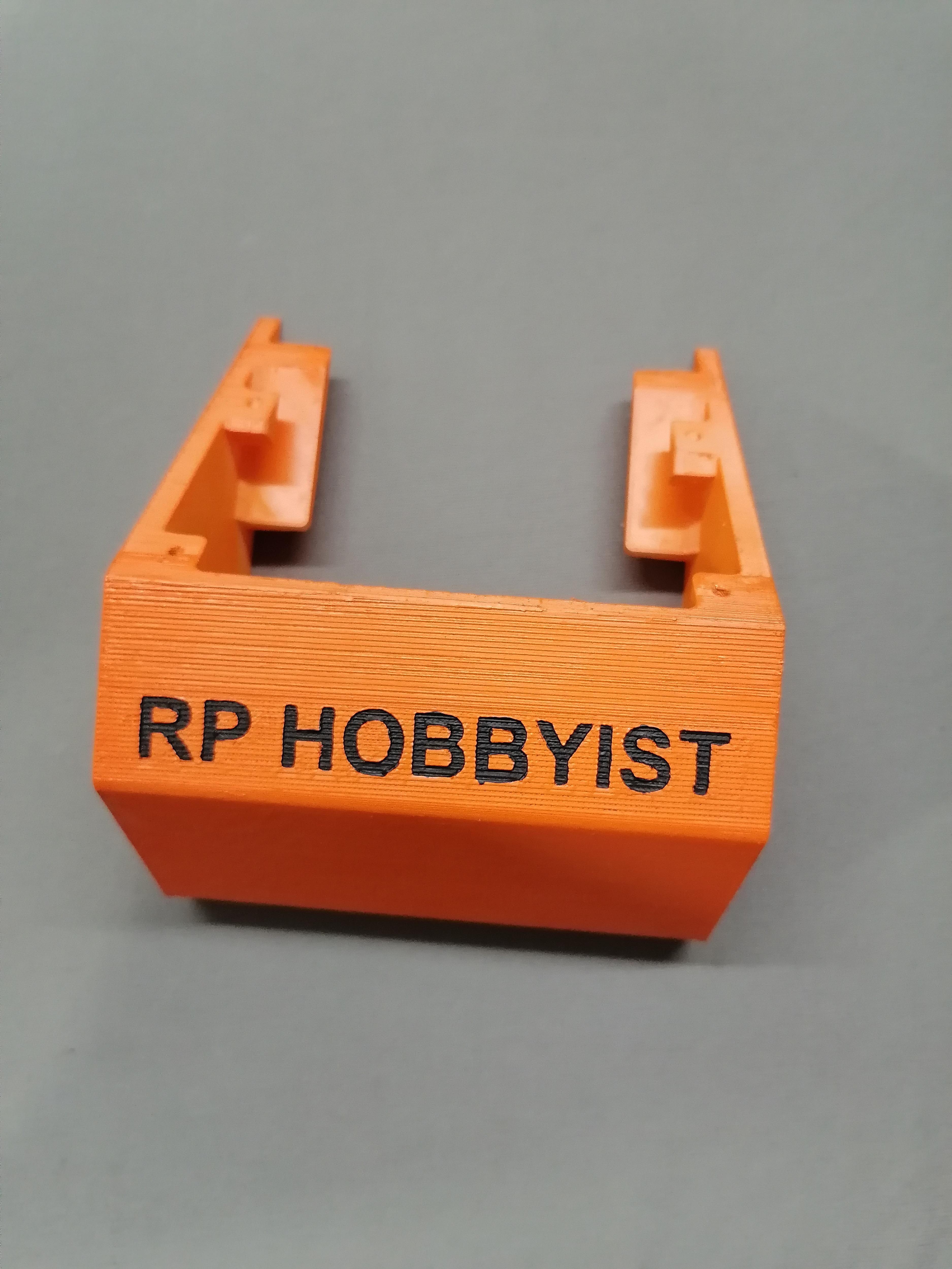
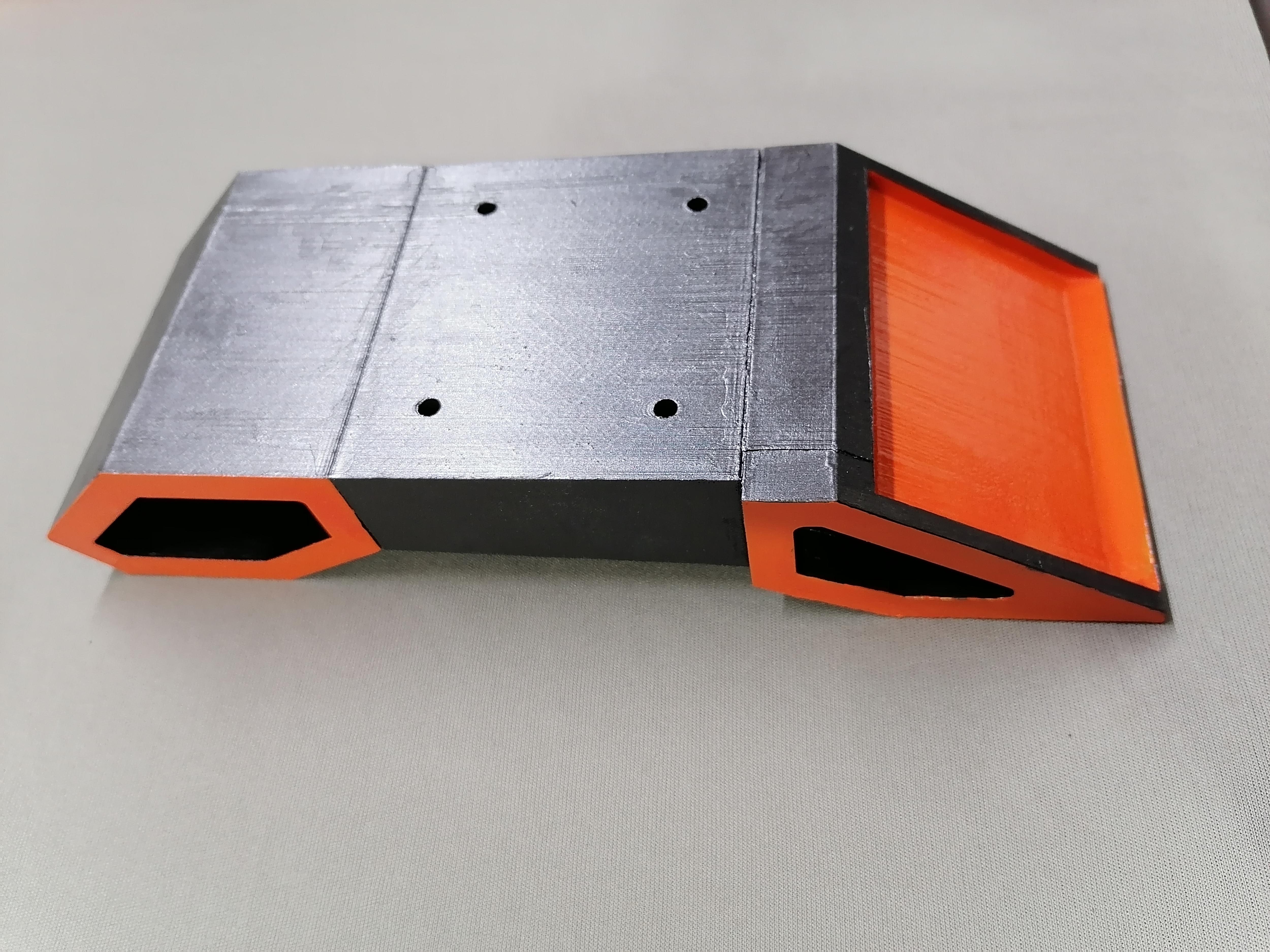
Joining the Base Stand of CPU
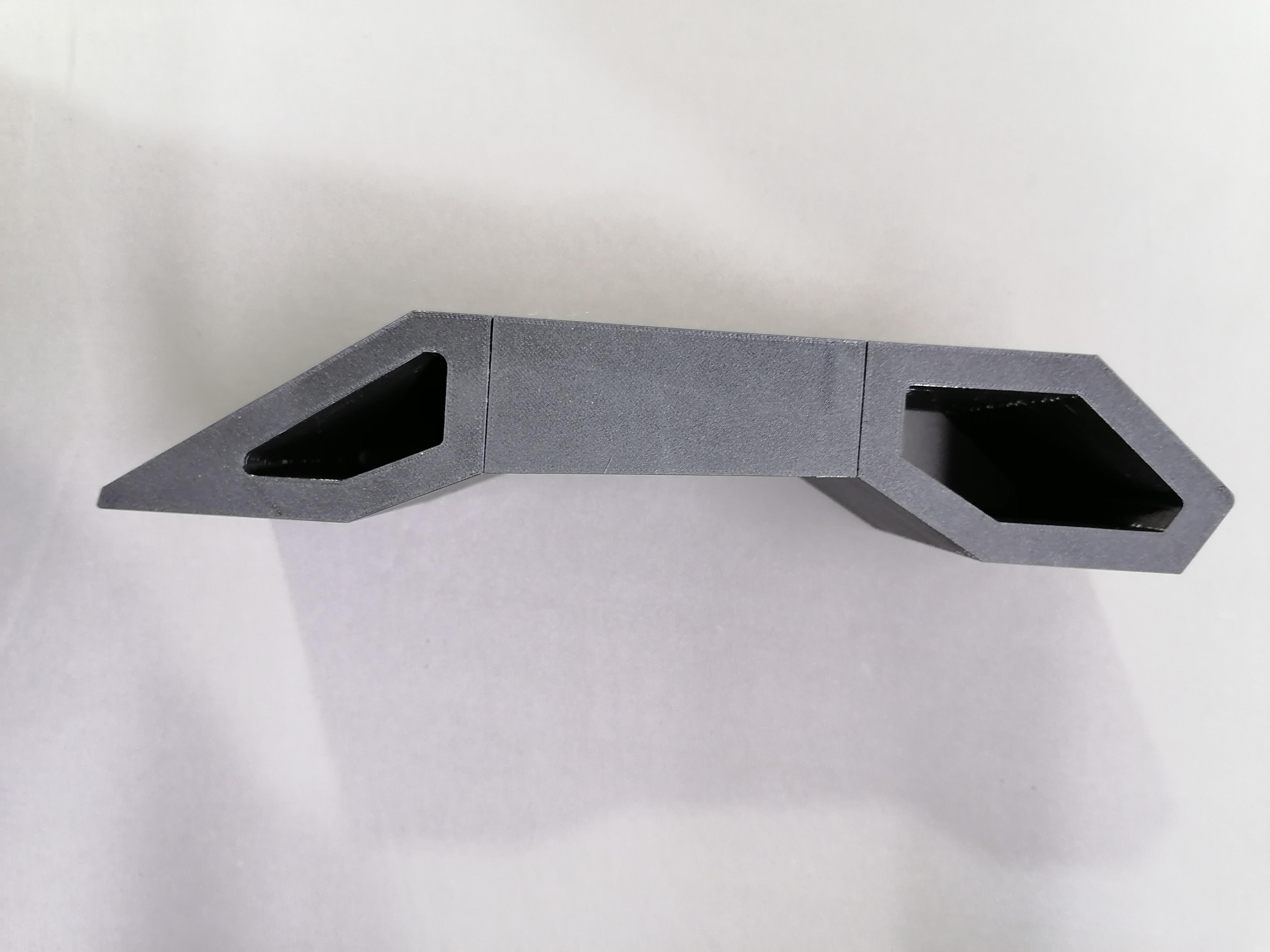
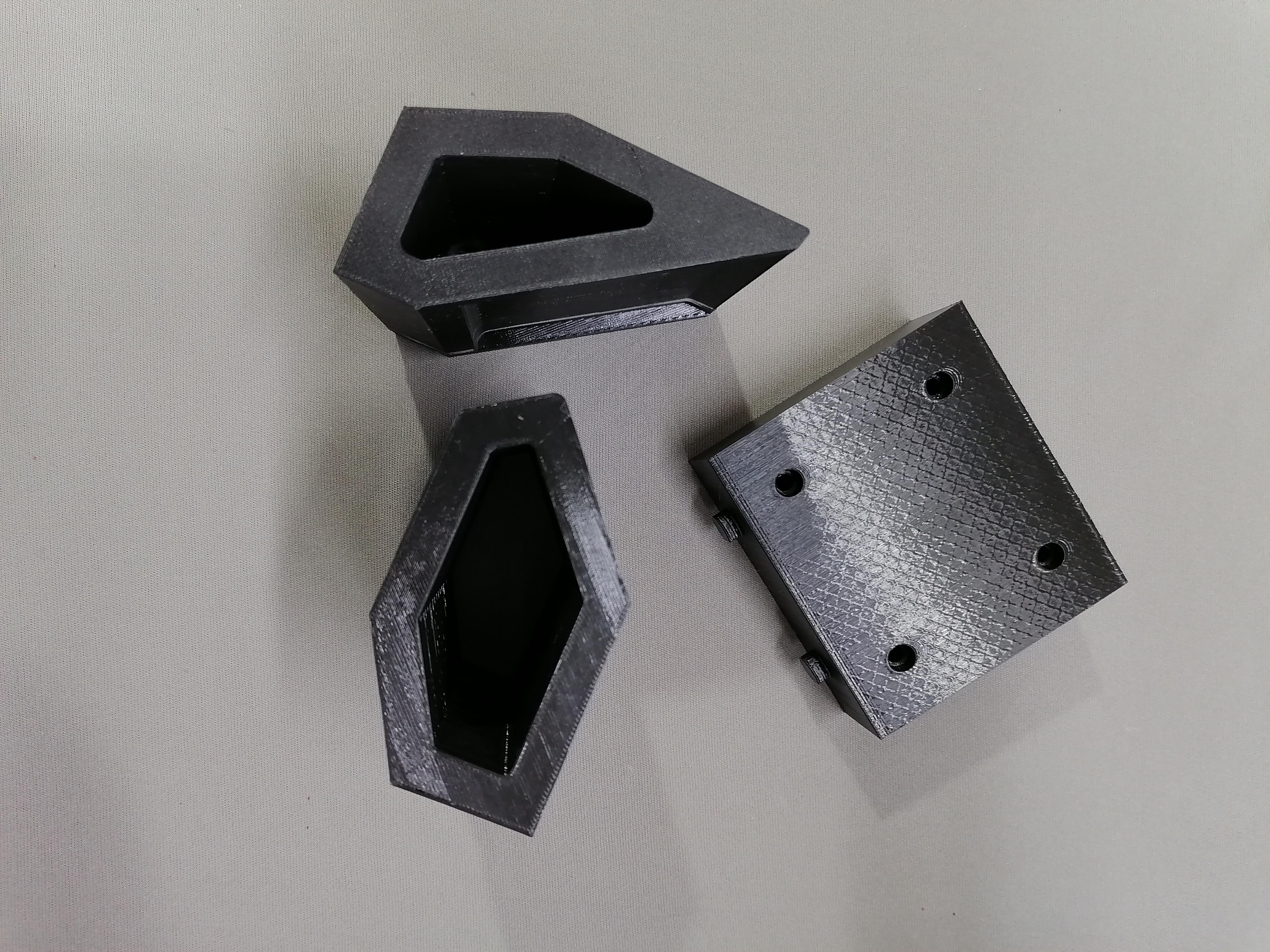
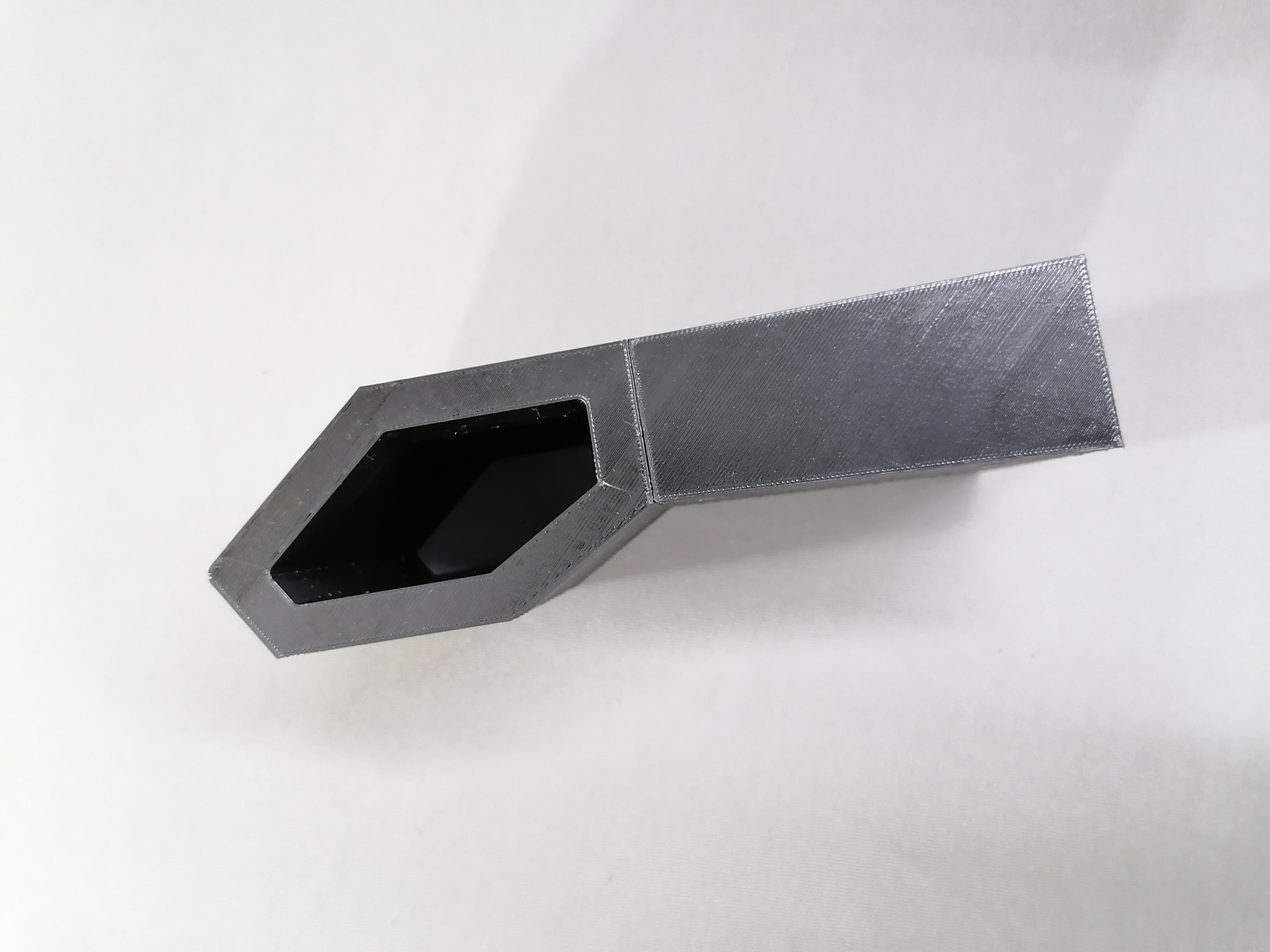

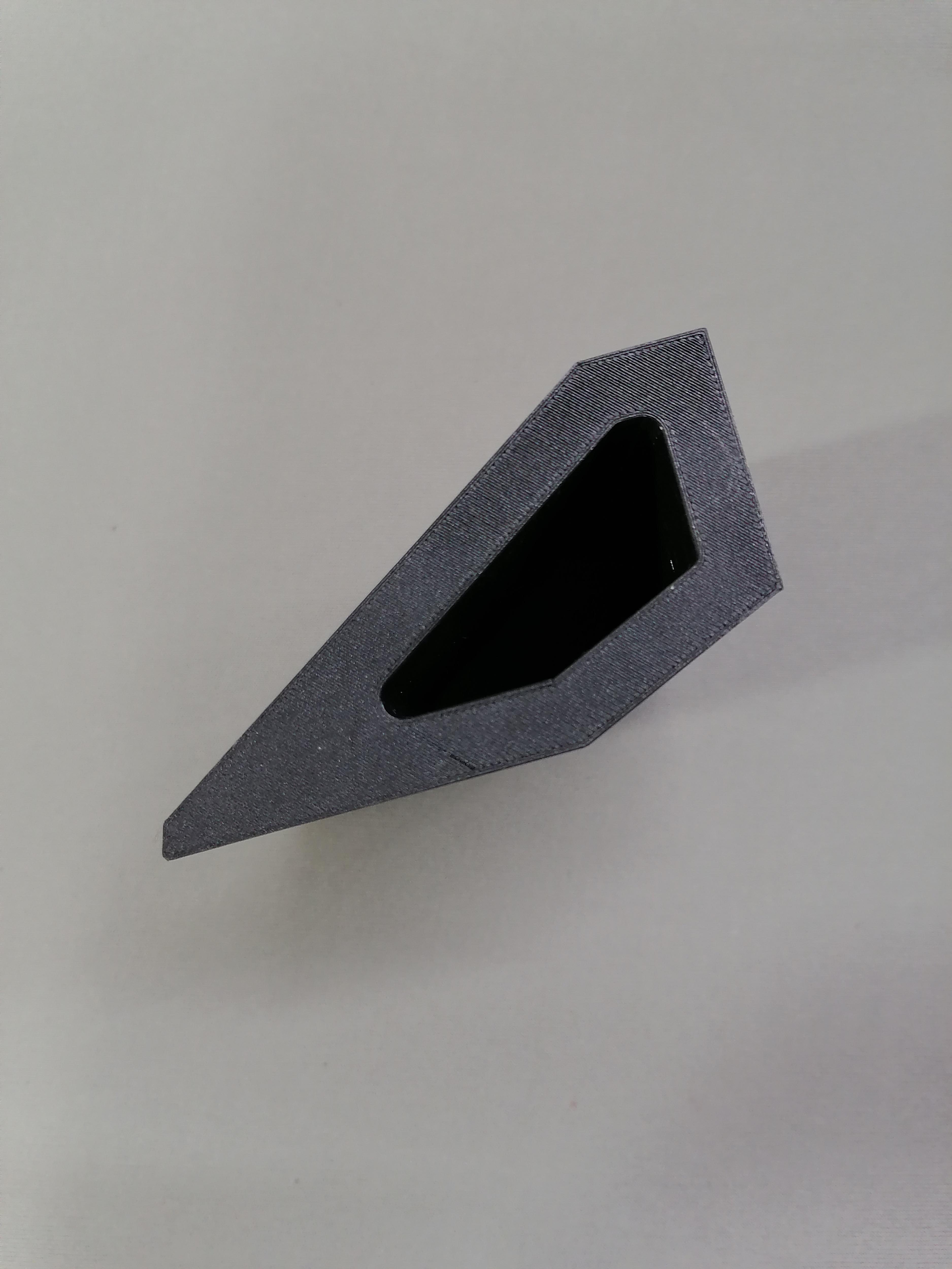
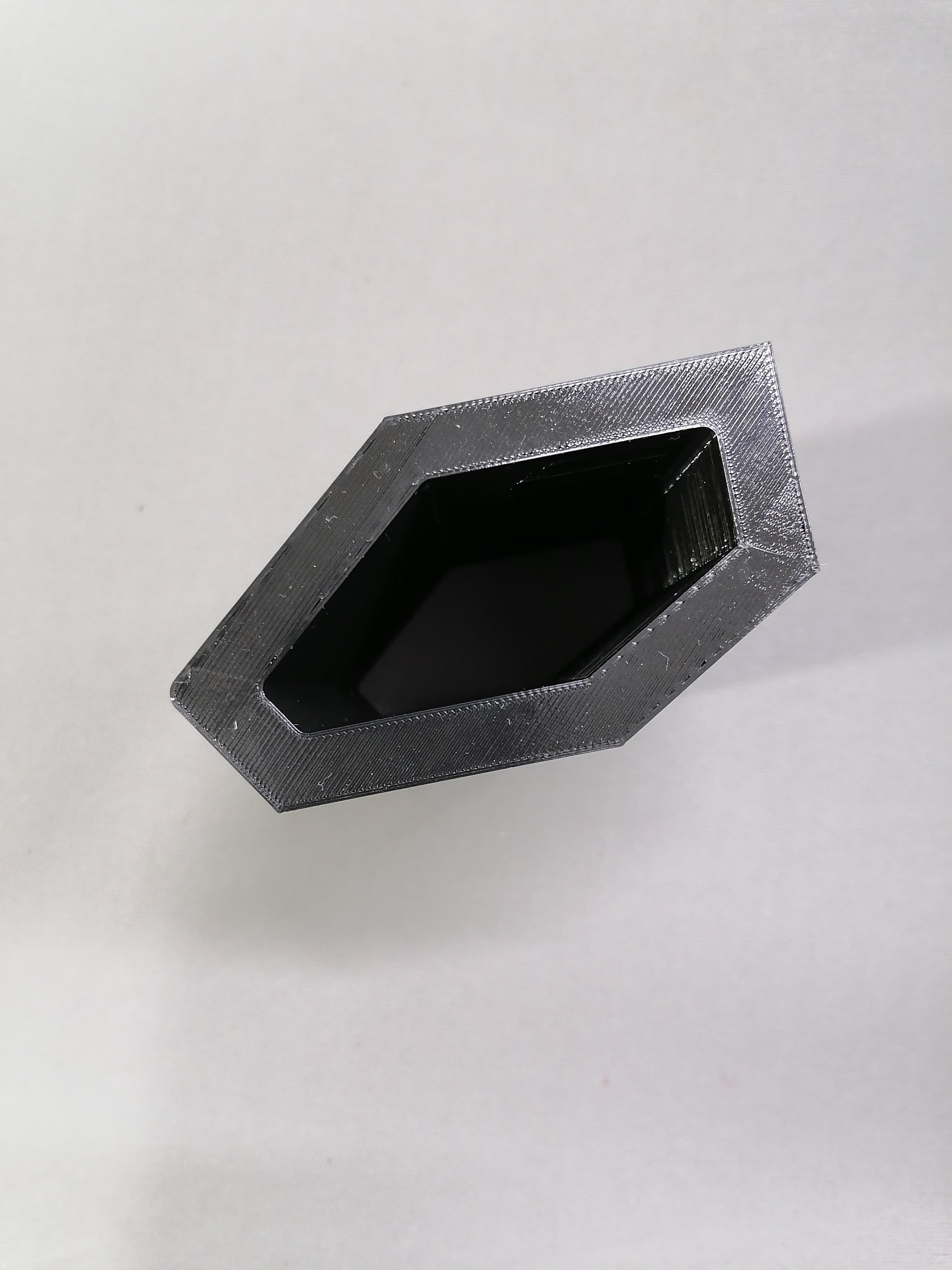
There is holes for matching parts and for fitting in each other. Use Super Glue to joint parts.
Note: Do this before painting.
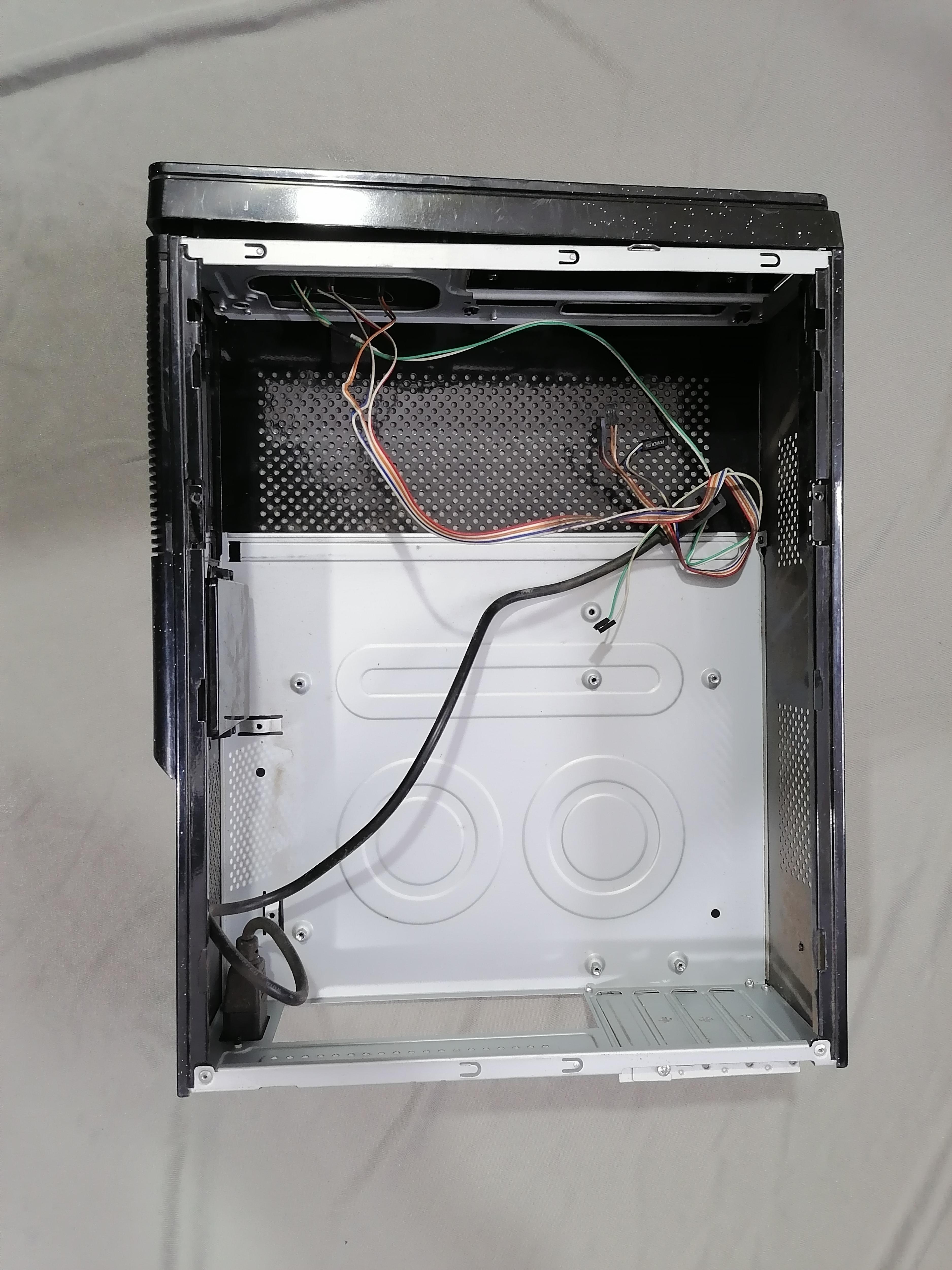
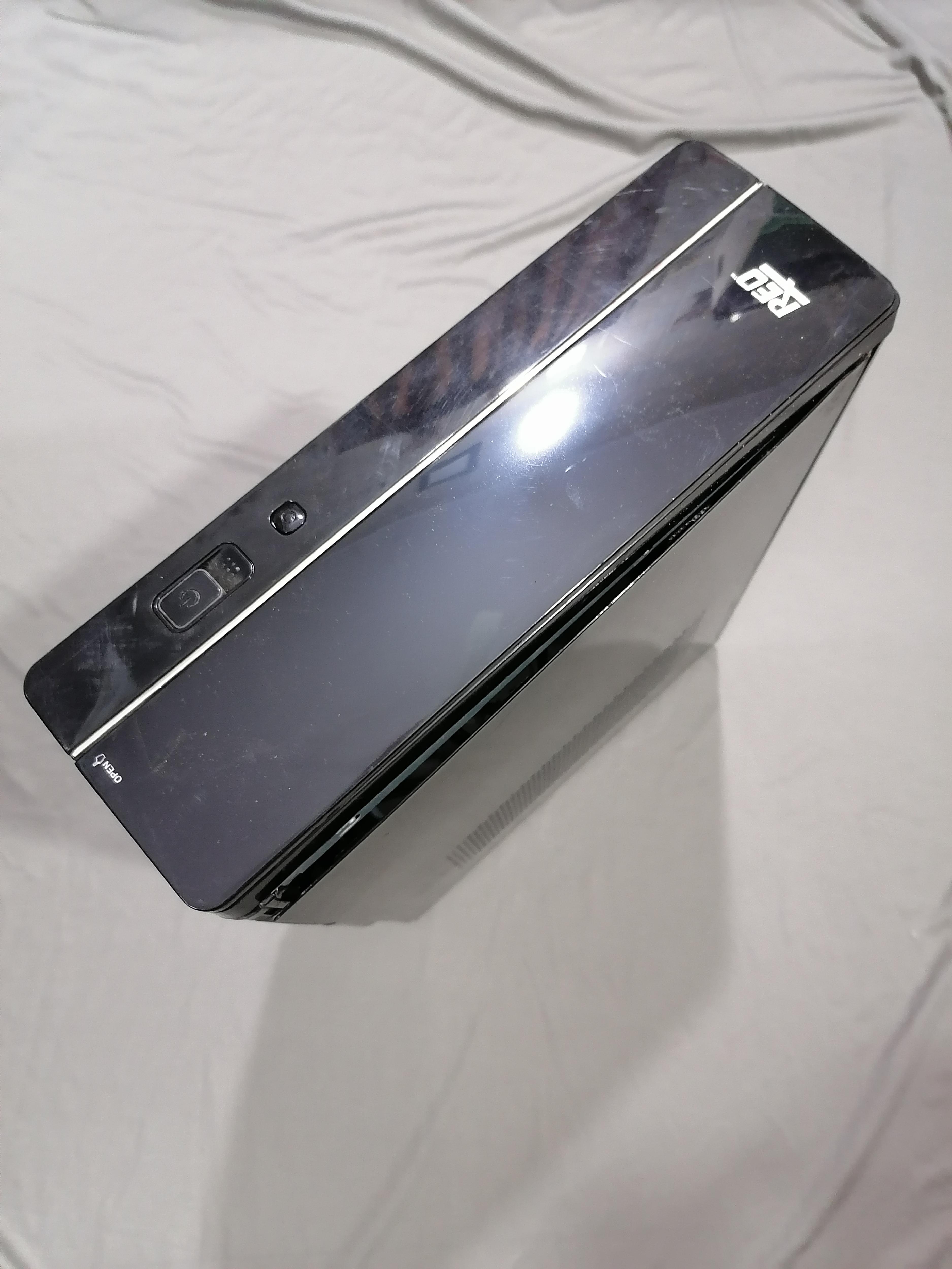
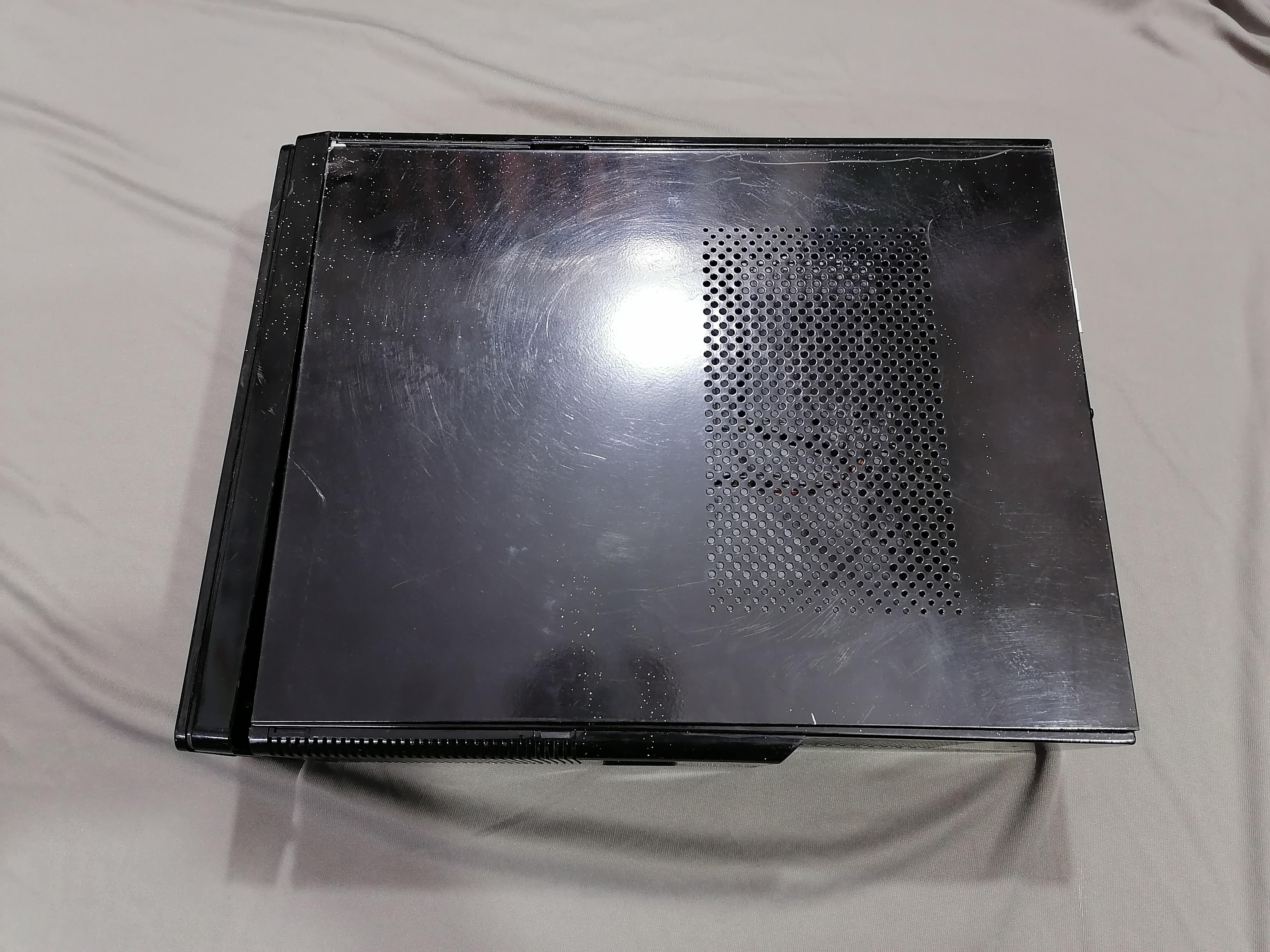
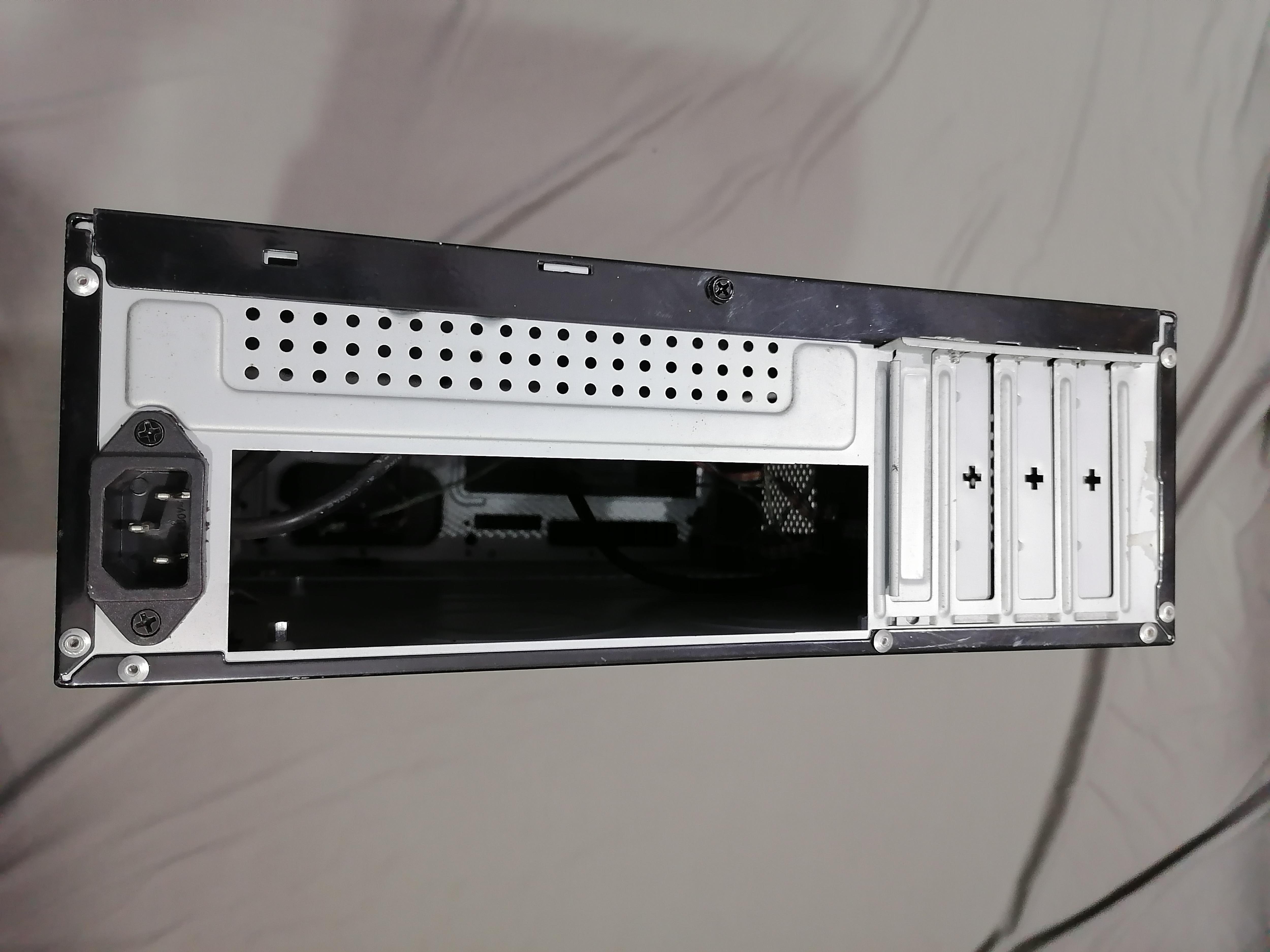
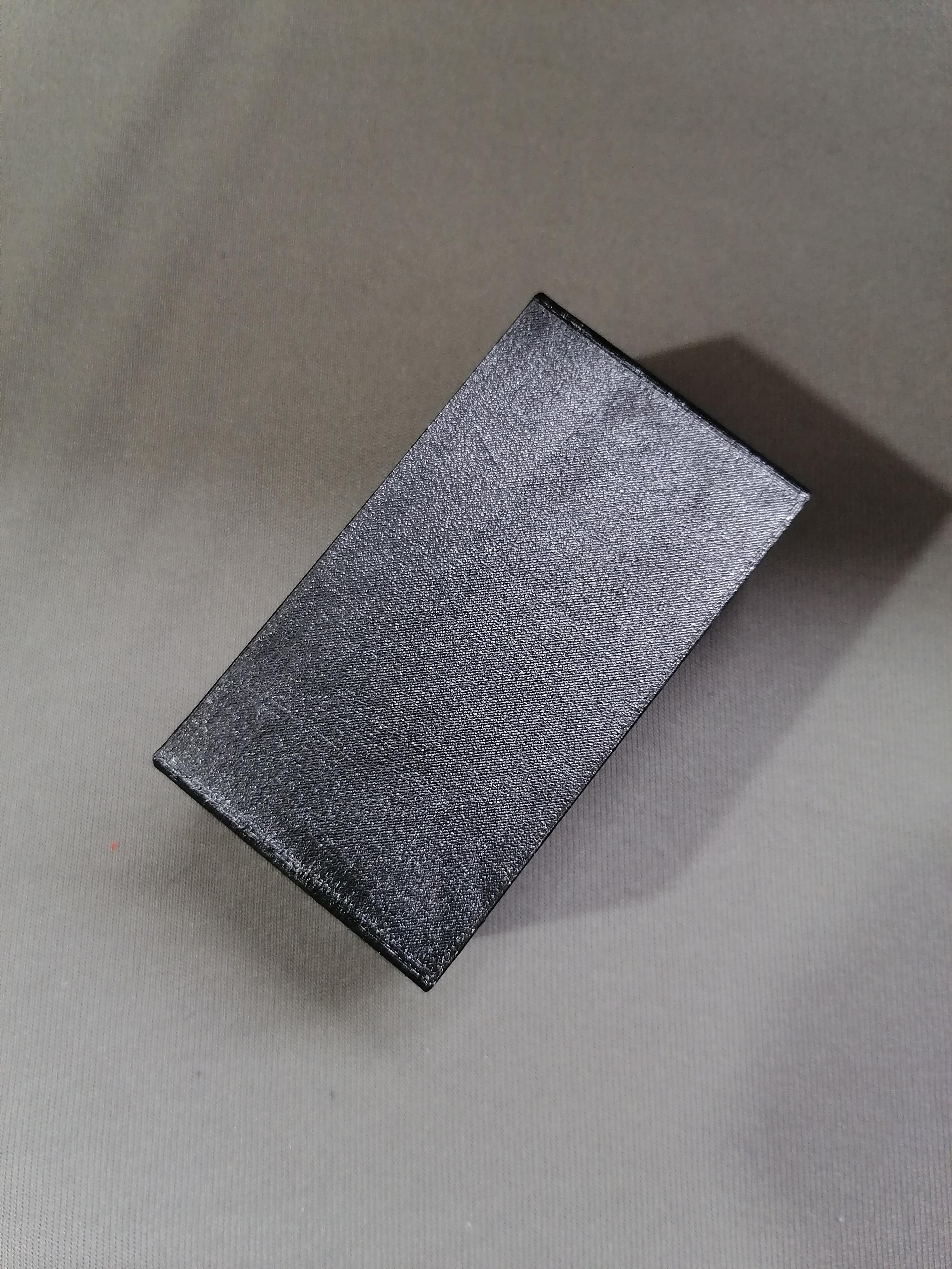
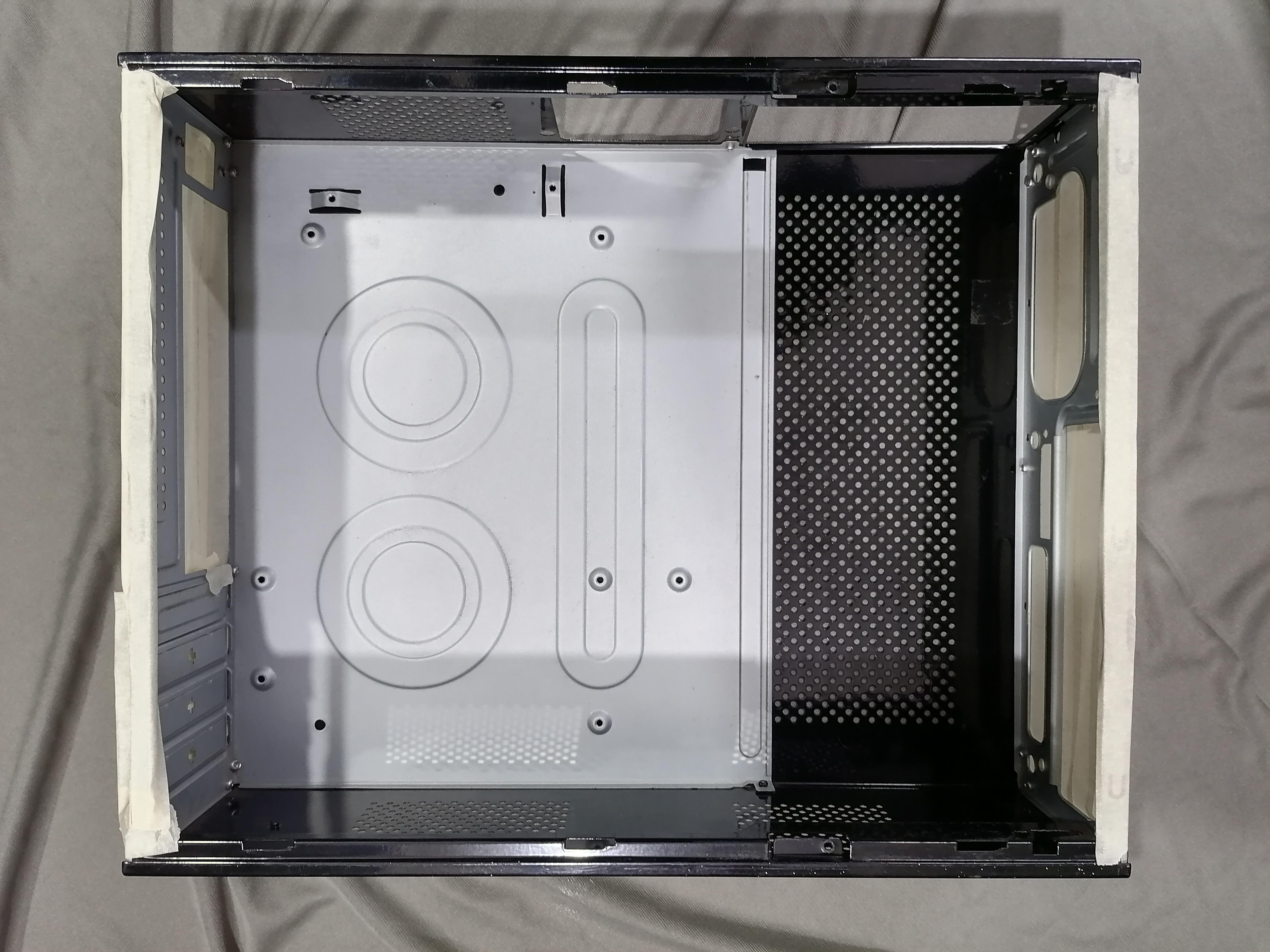
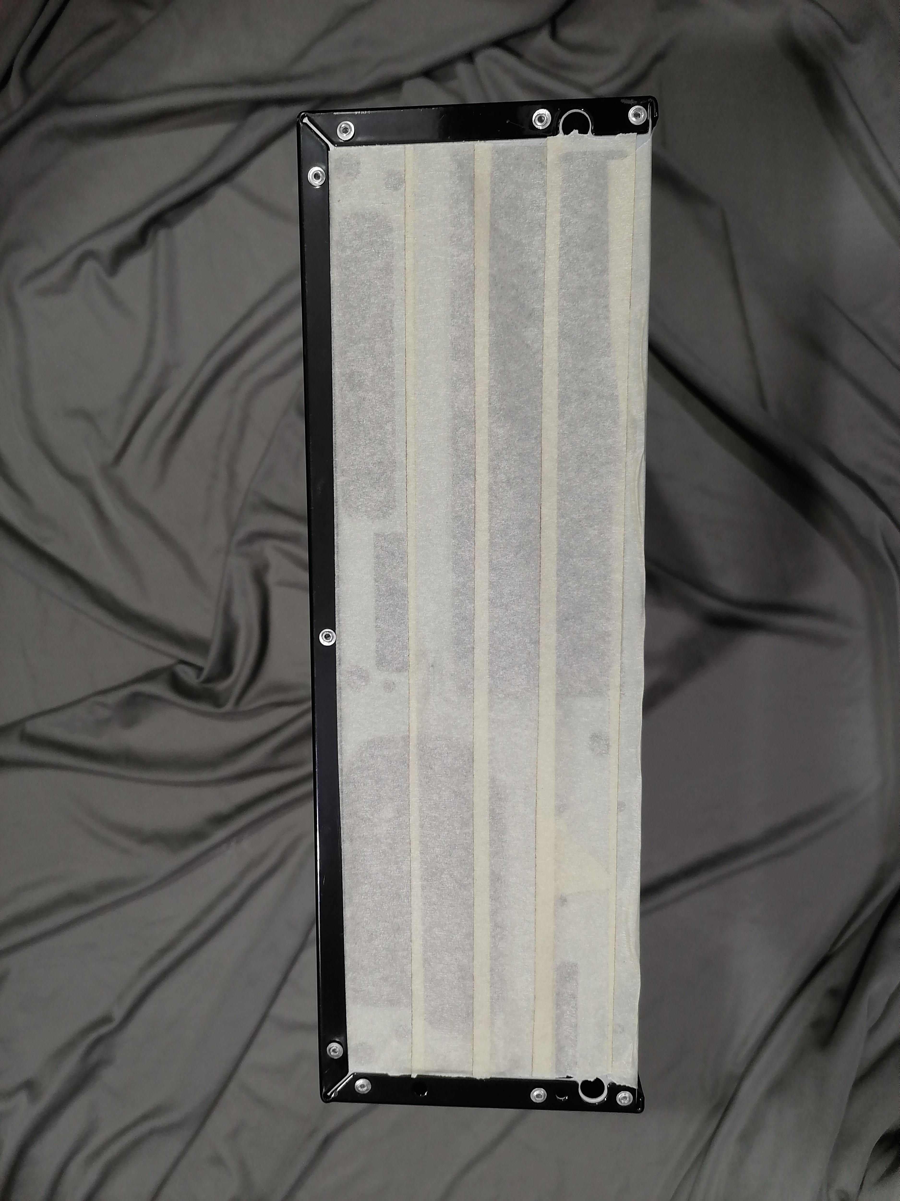
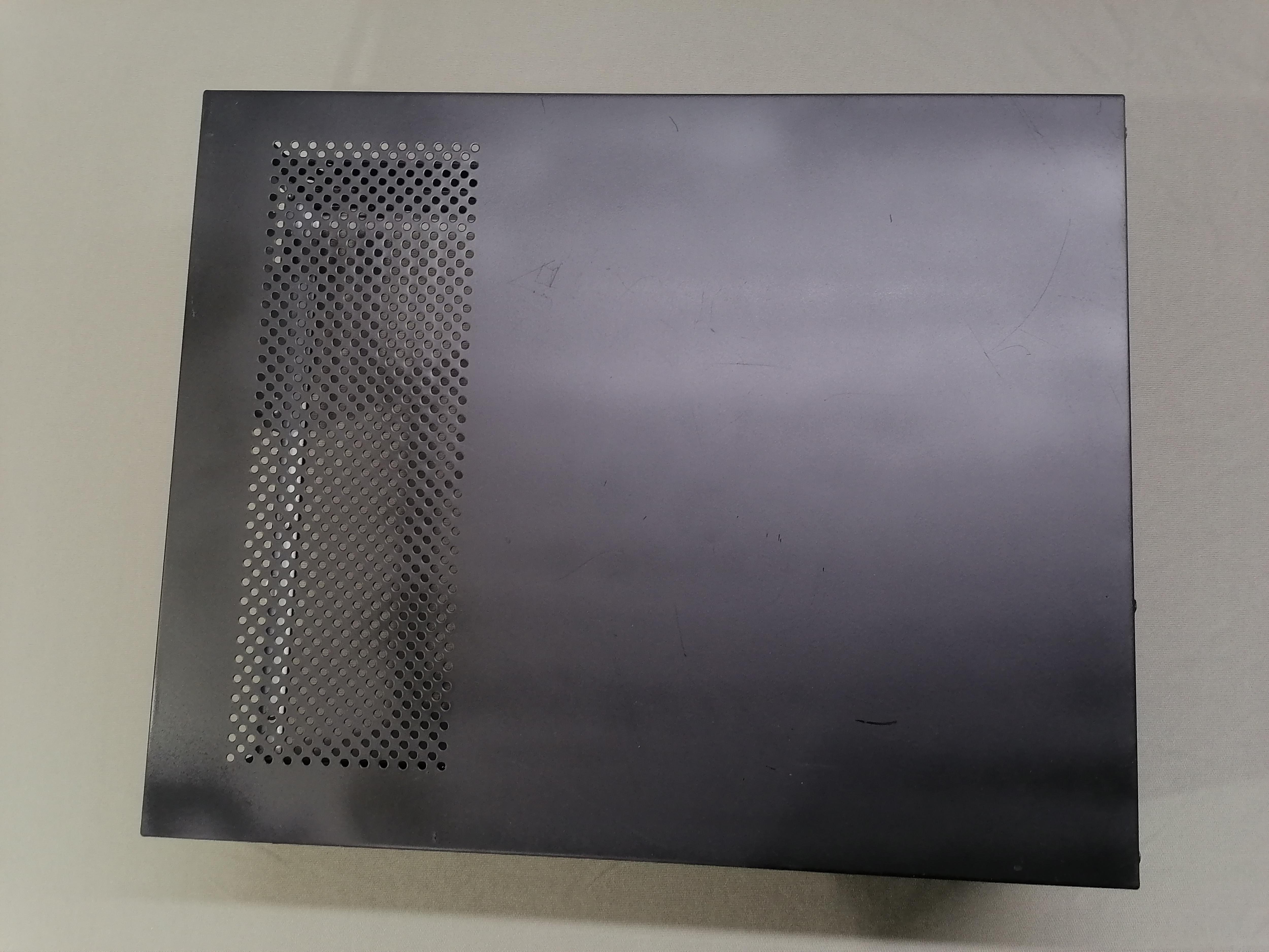
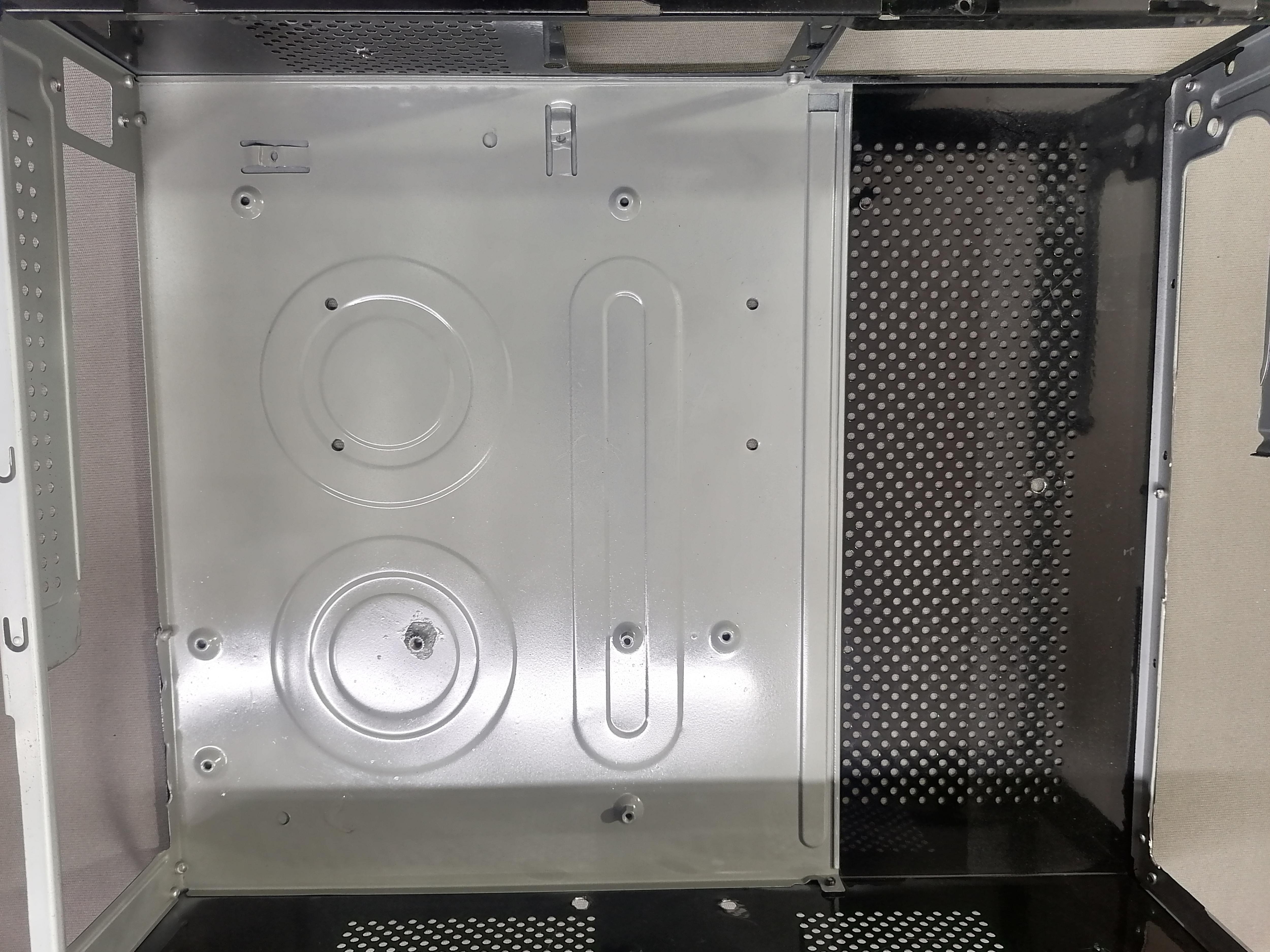
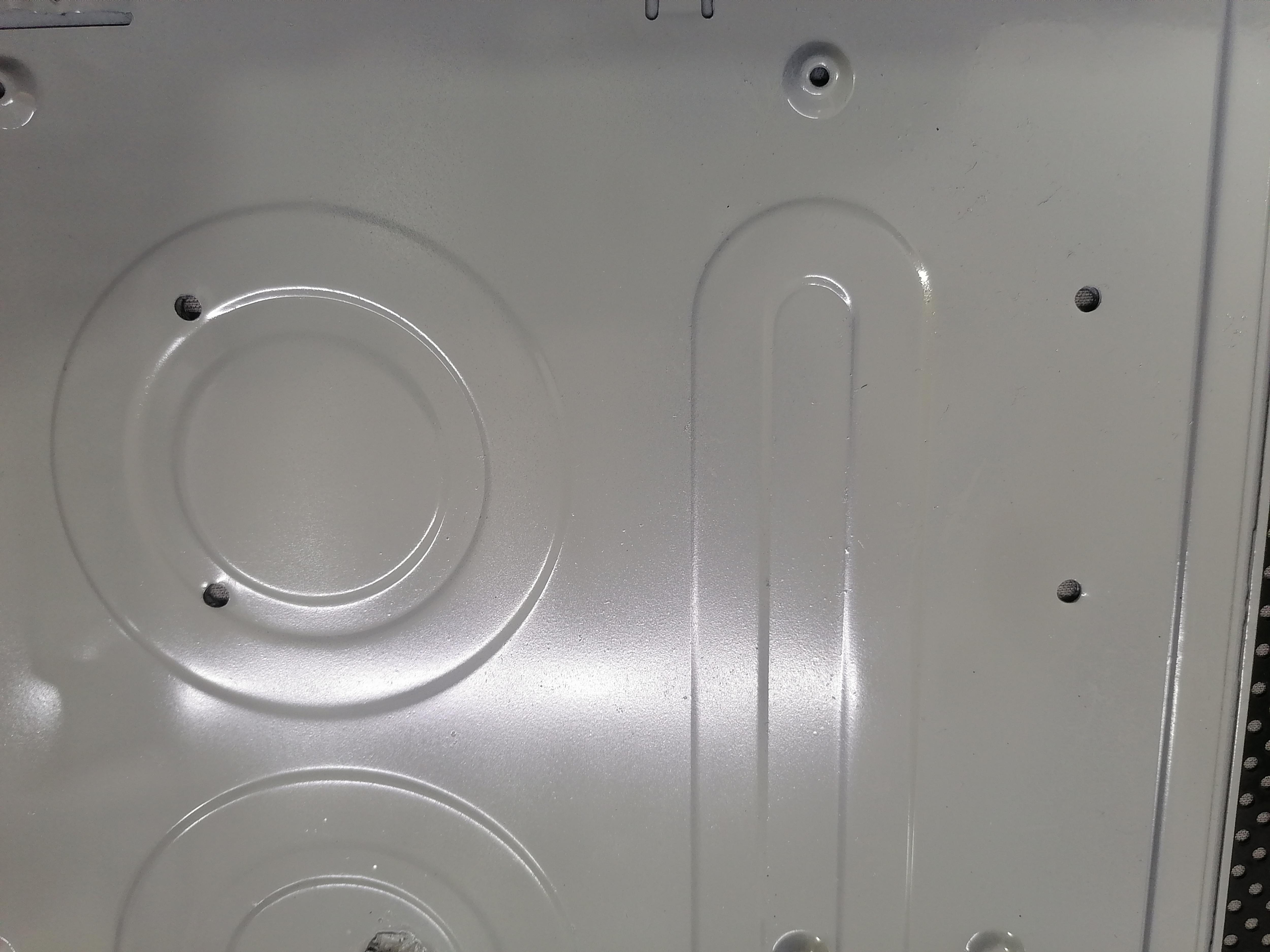
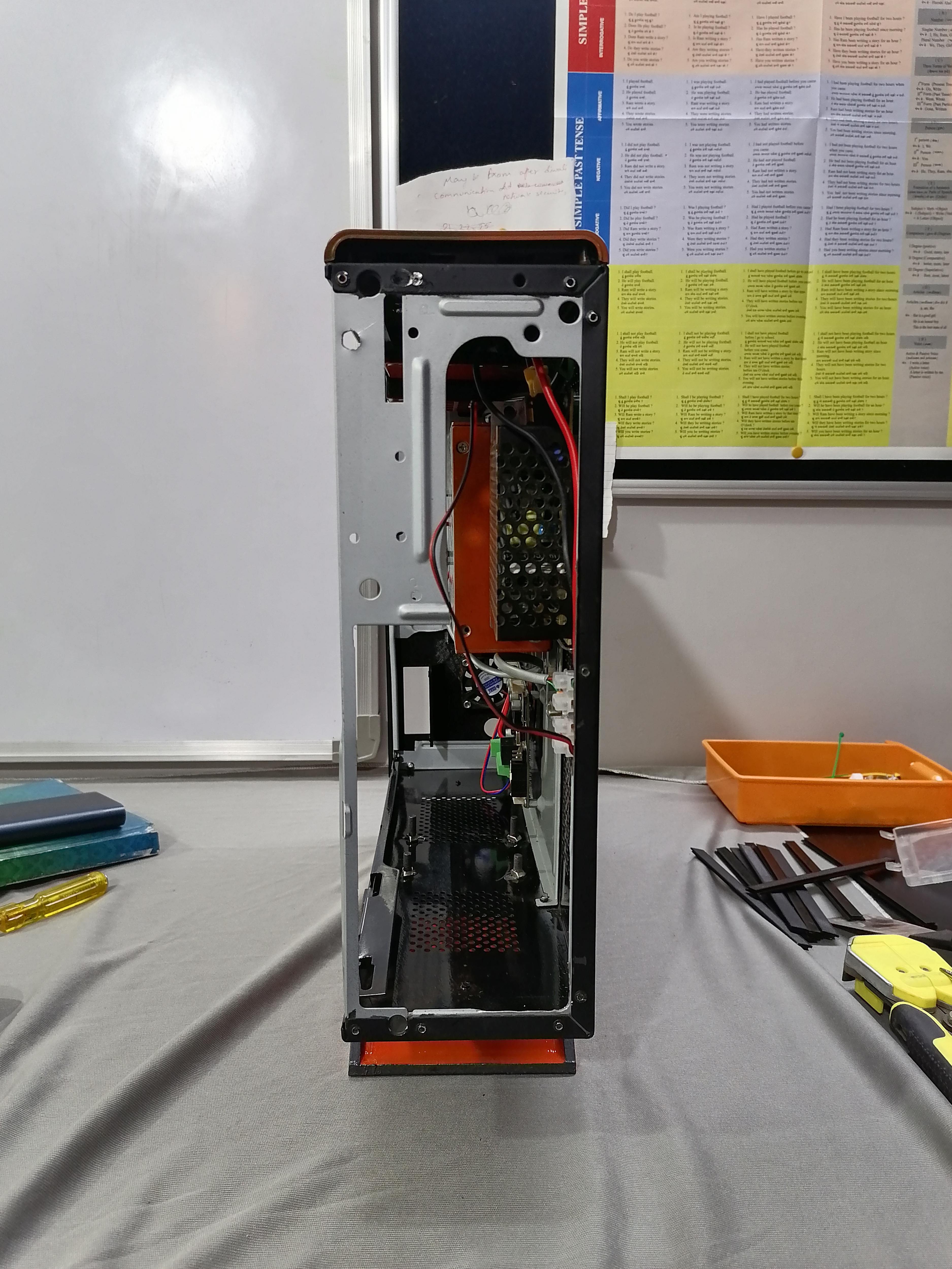
Using Old CPU Case


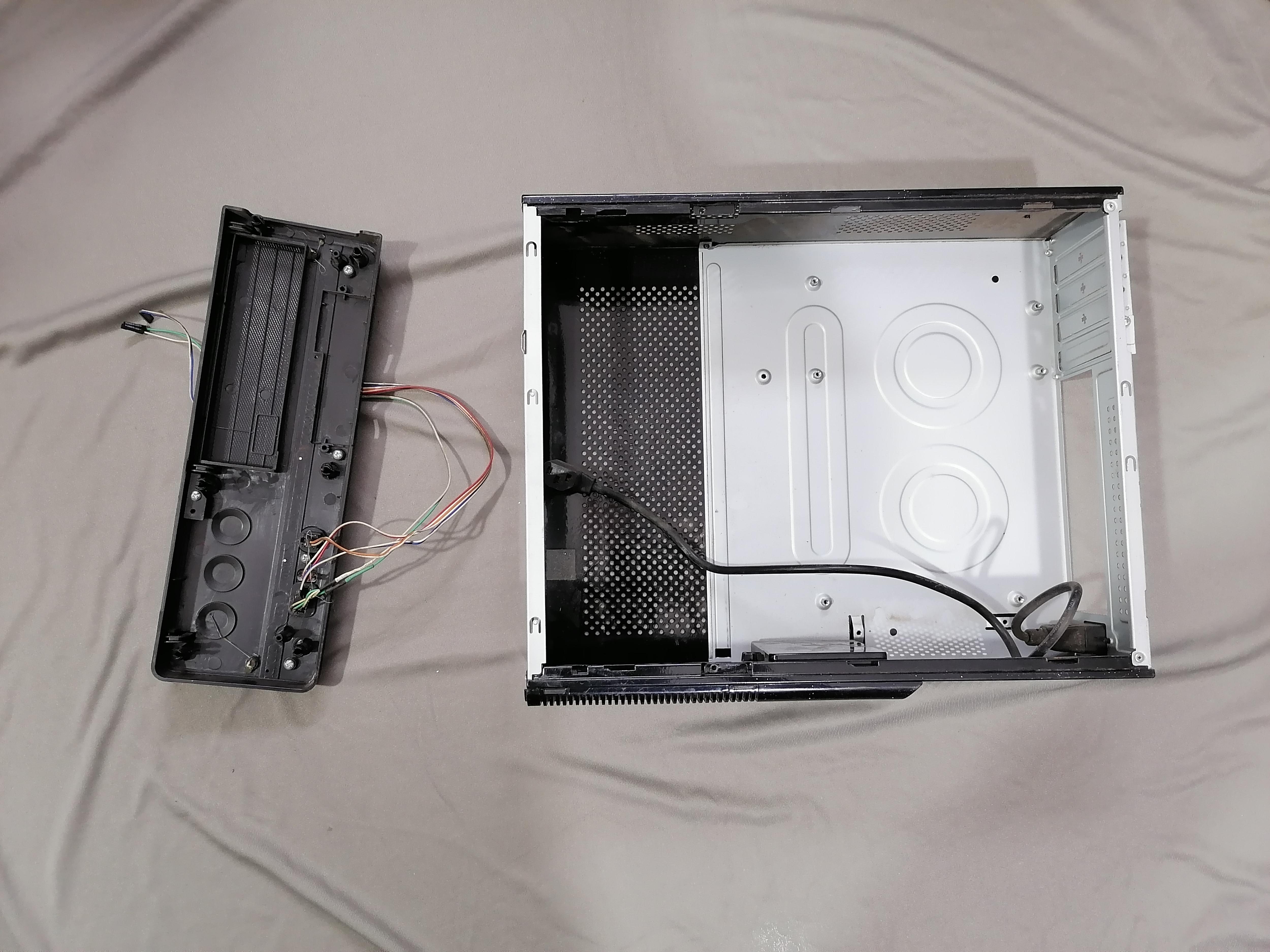
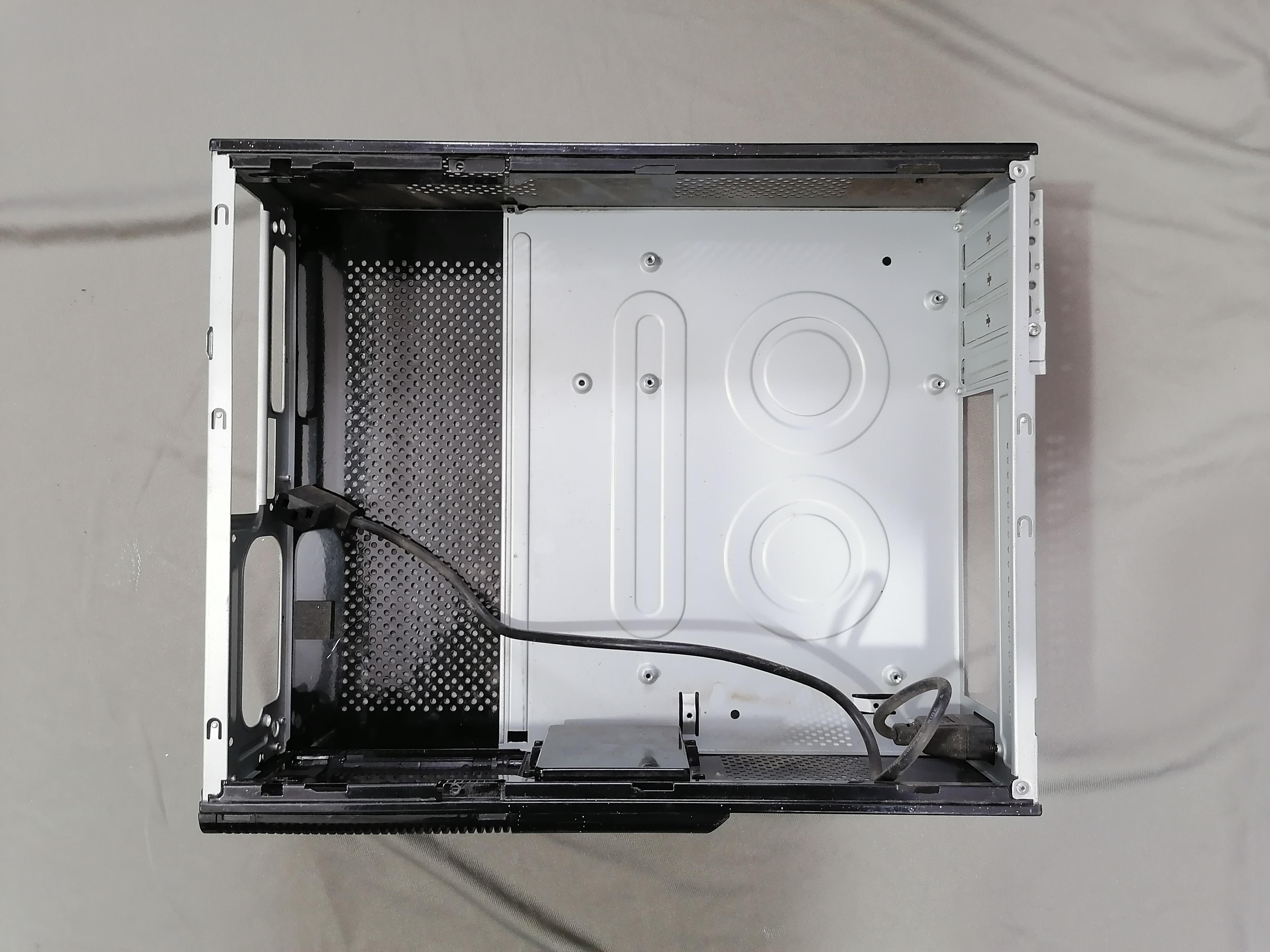


Here I am using an old CPU Case therefore Cleaning the Case and remove all parts from CPU Case.
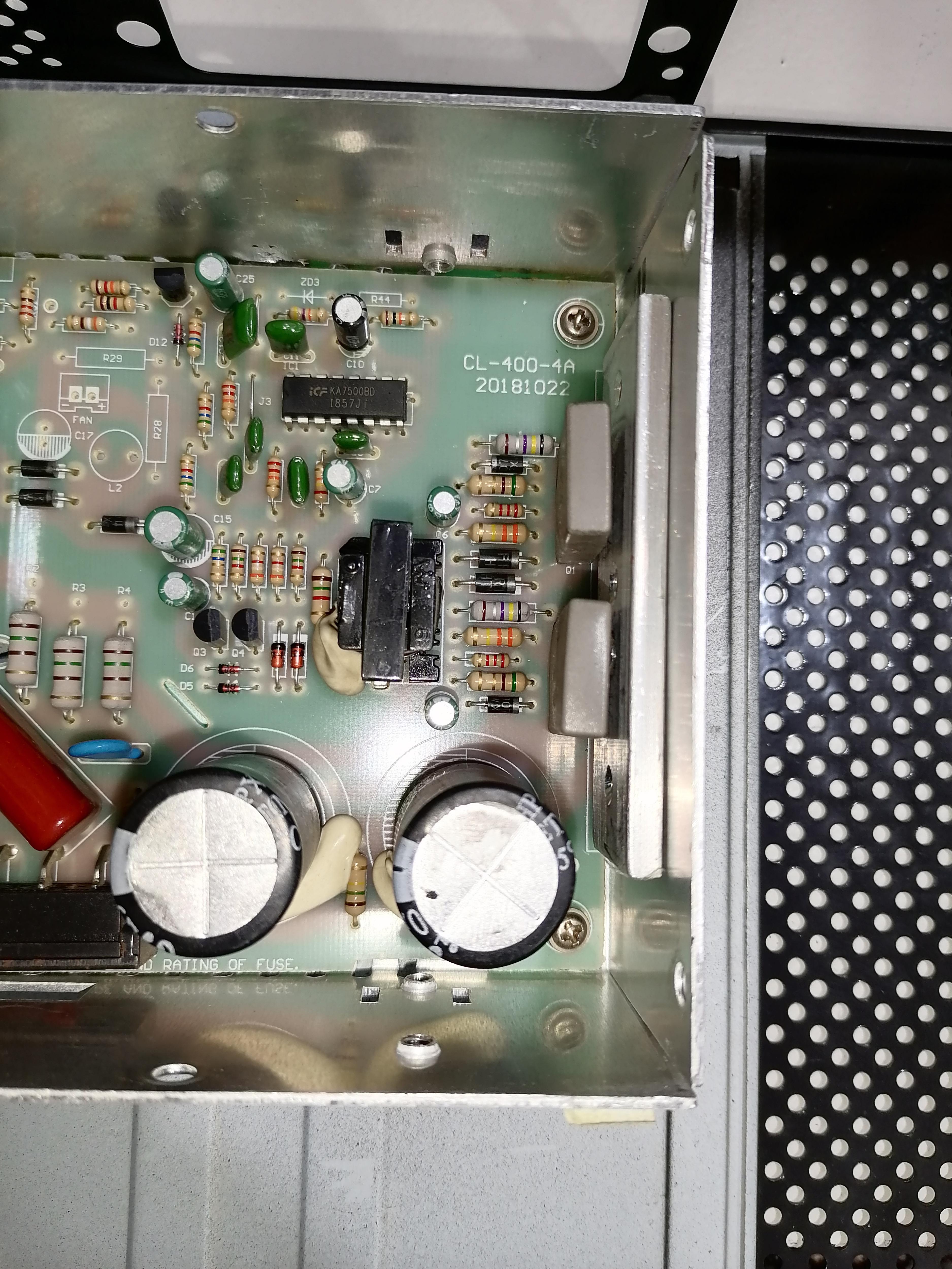
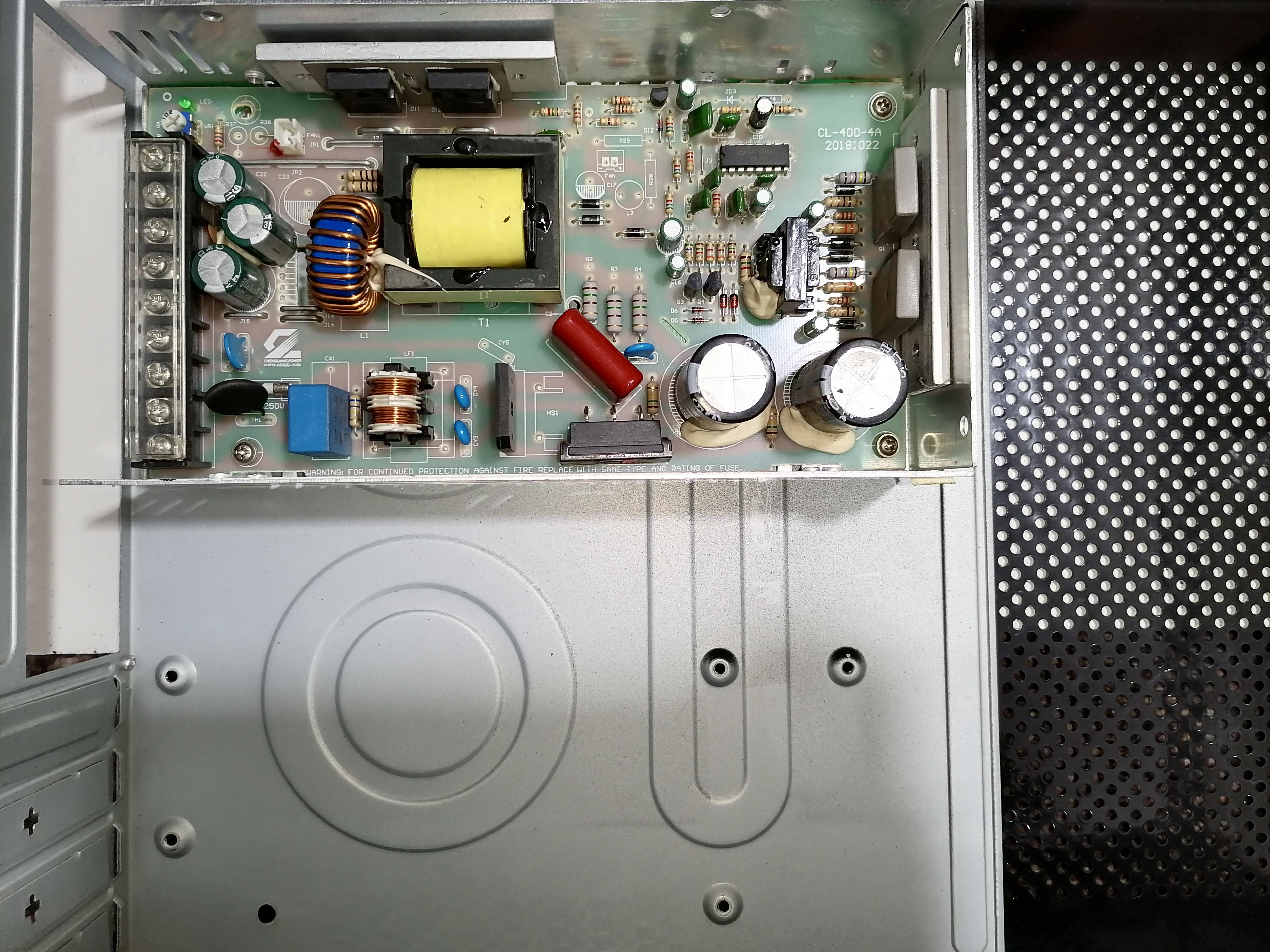
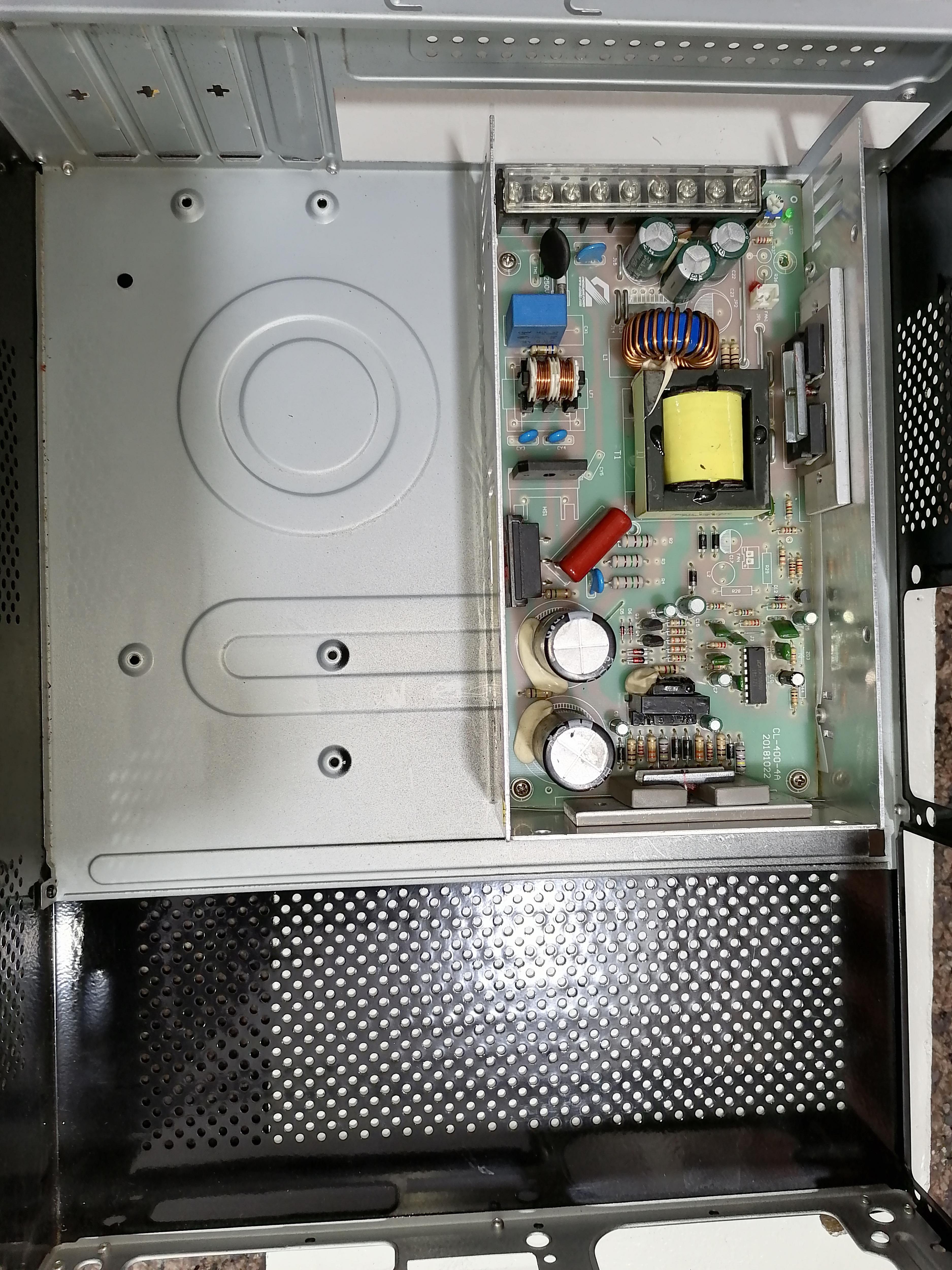
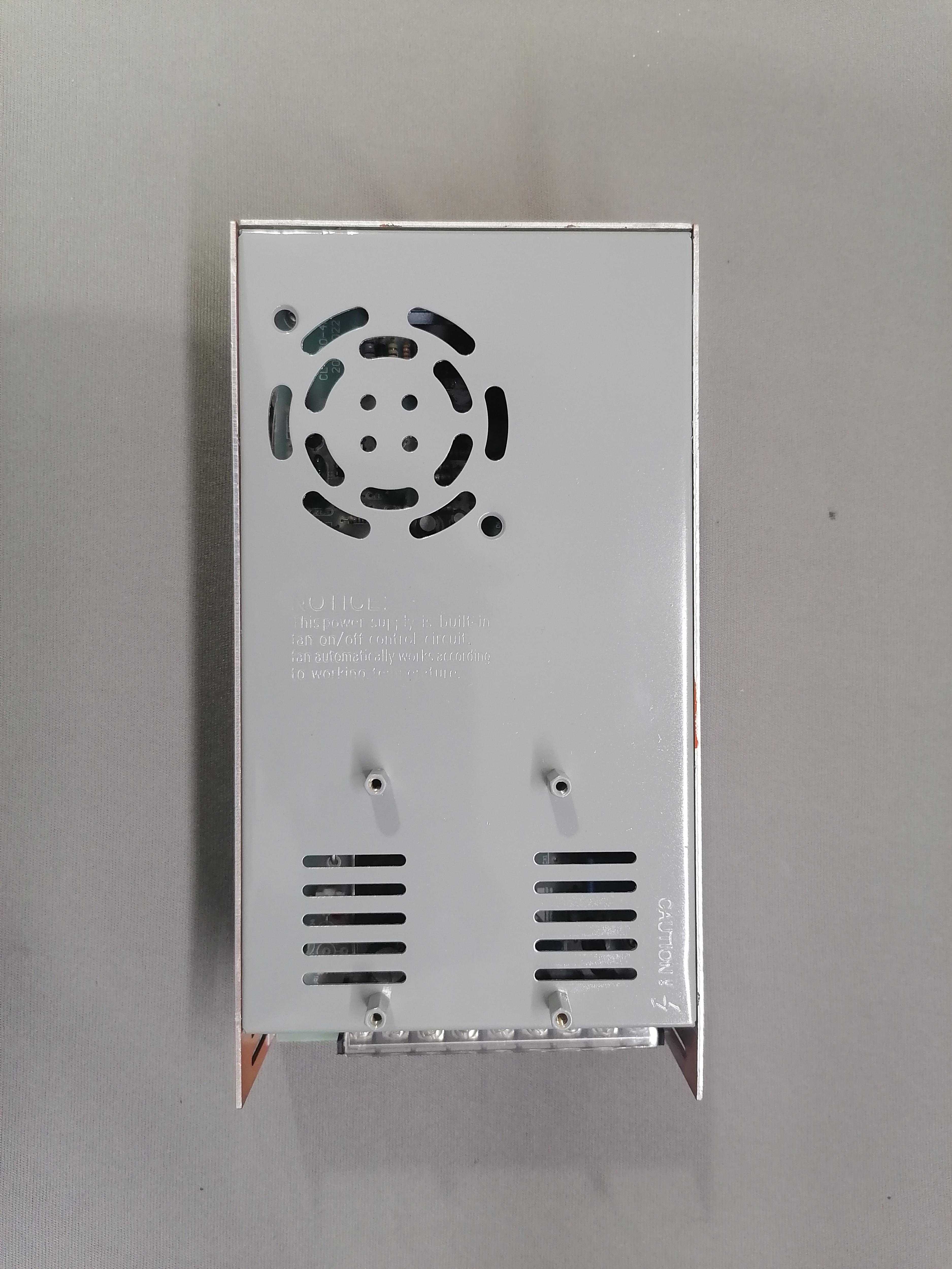
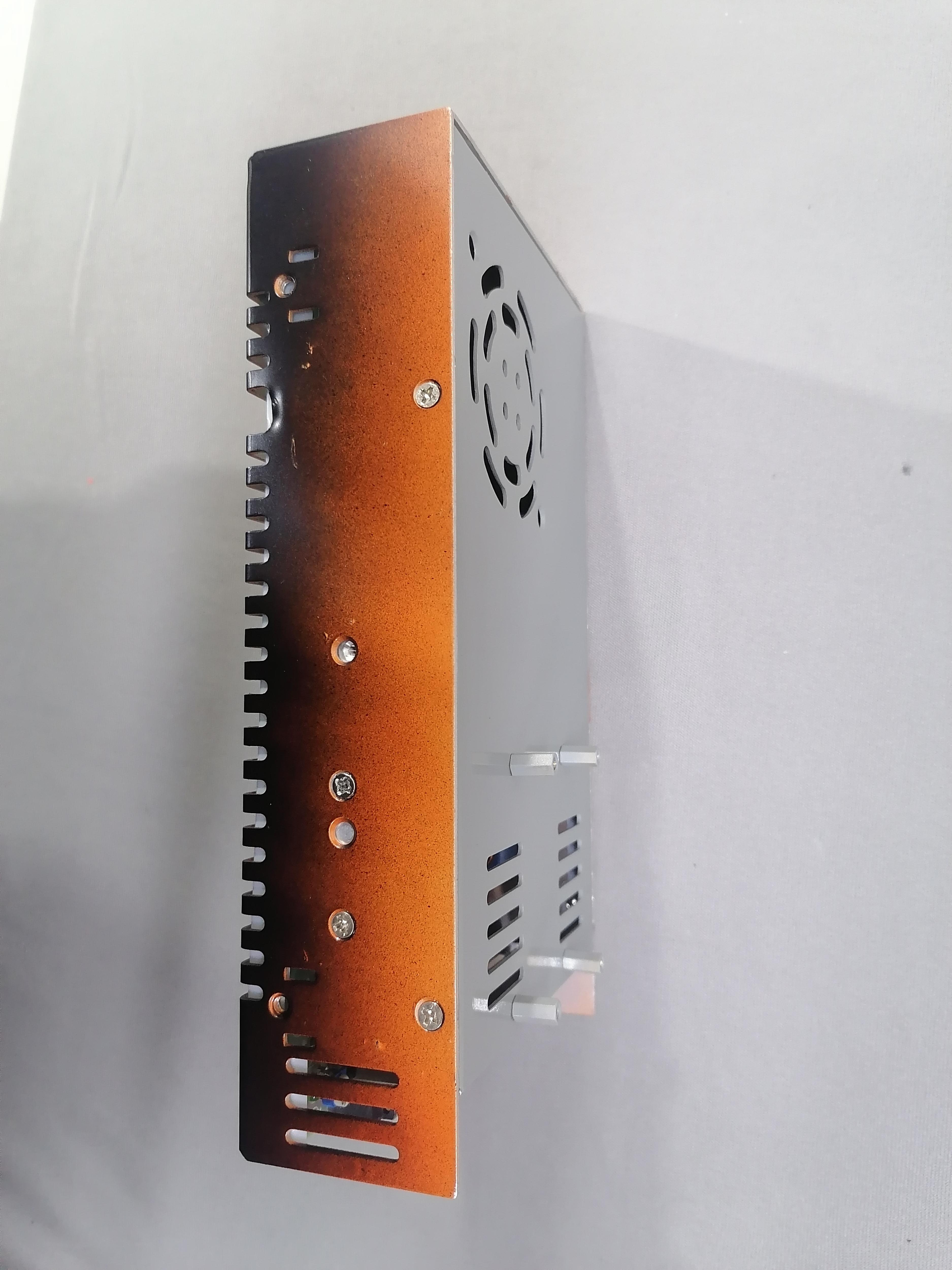
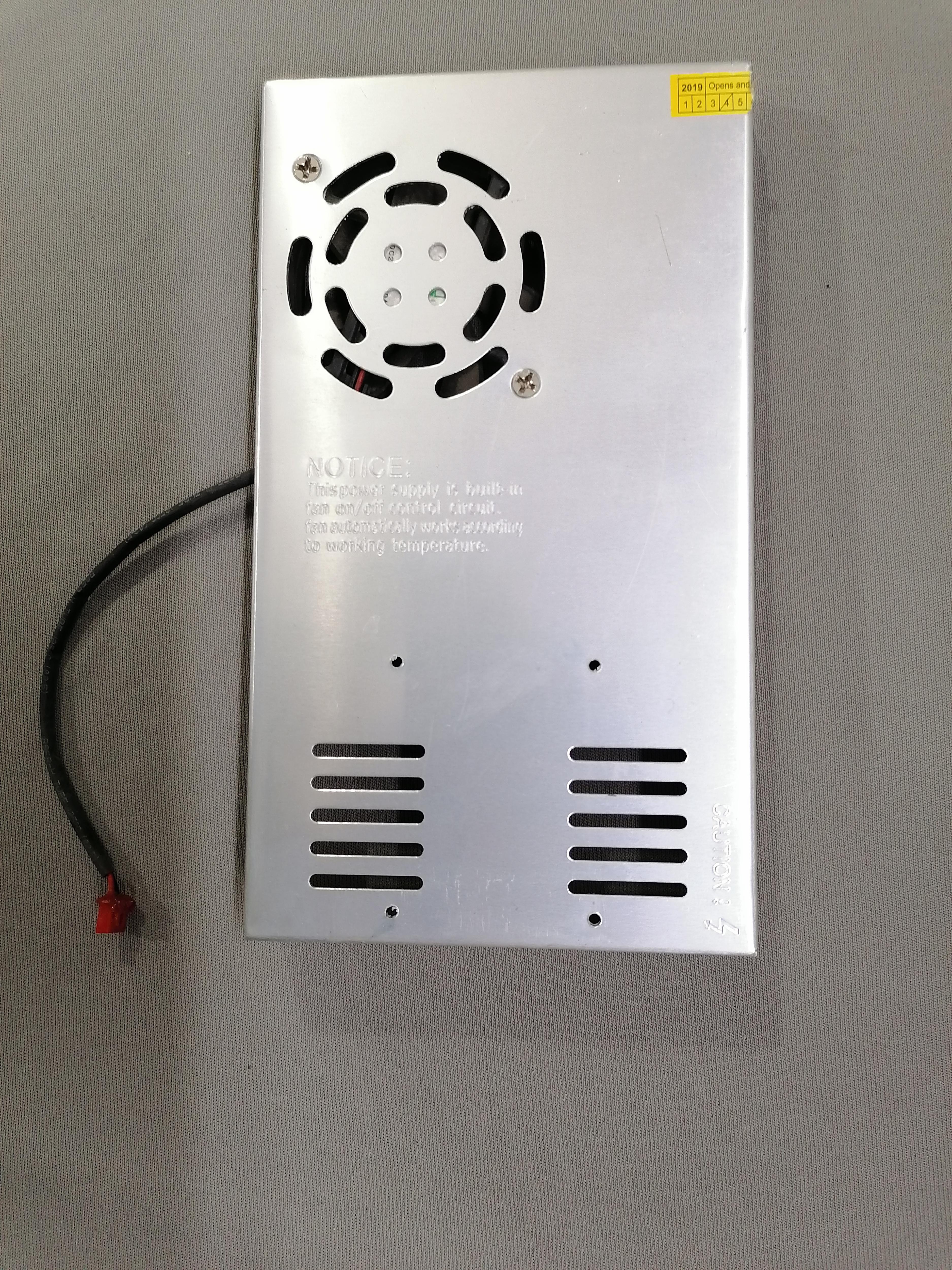
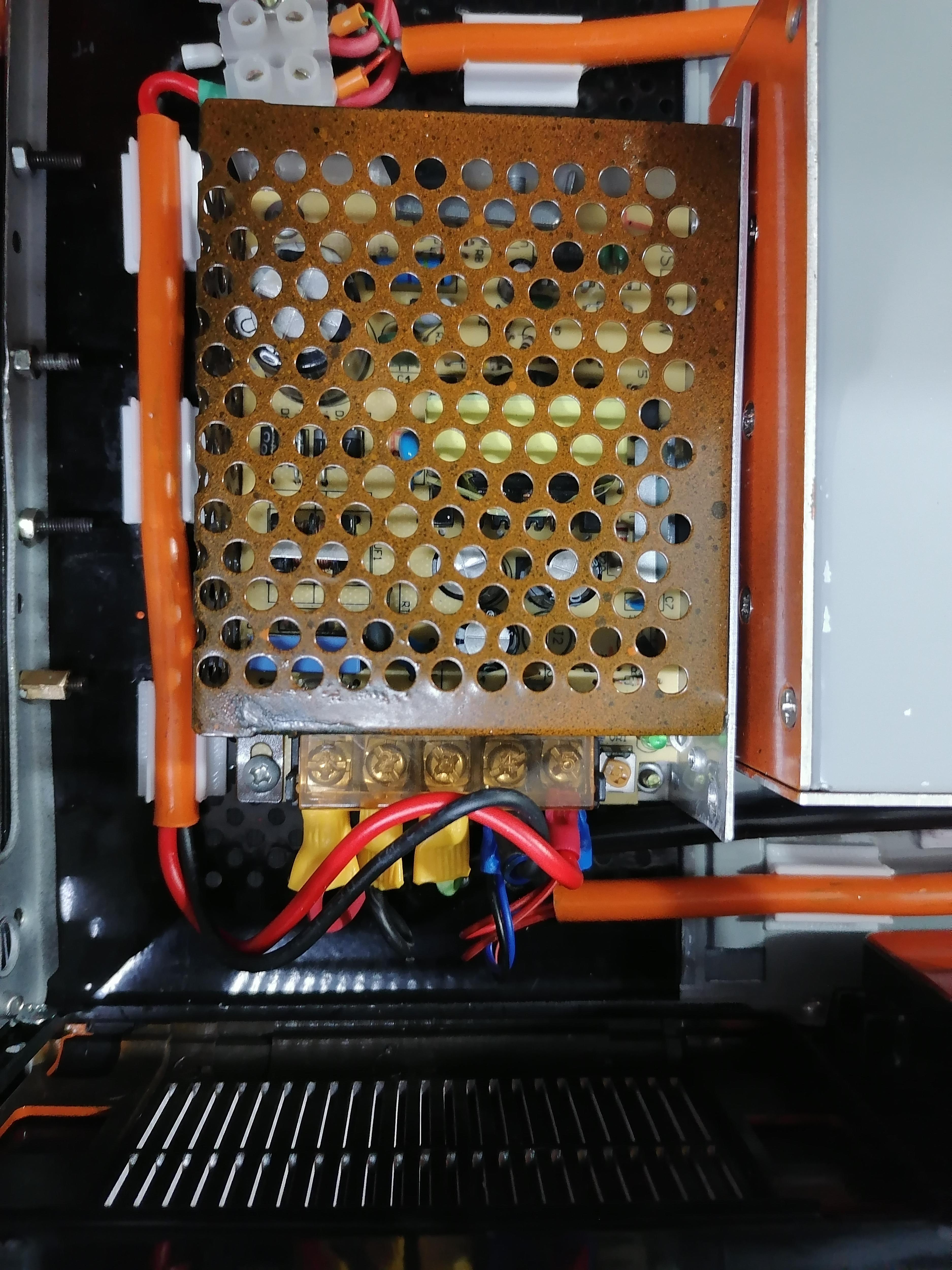
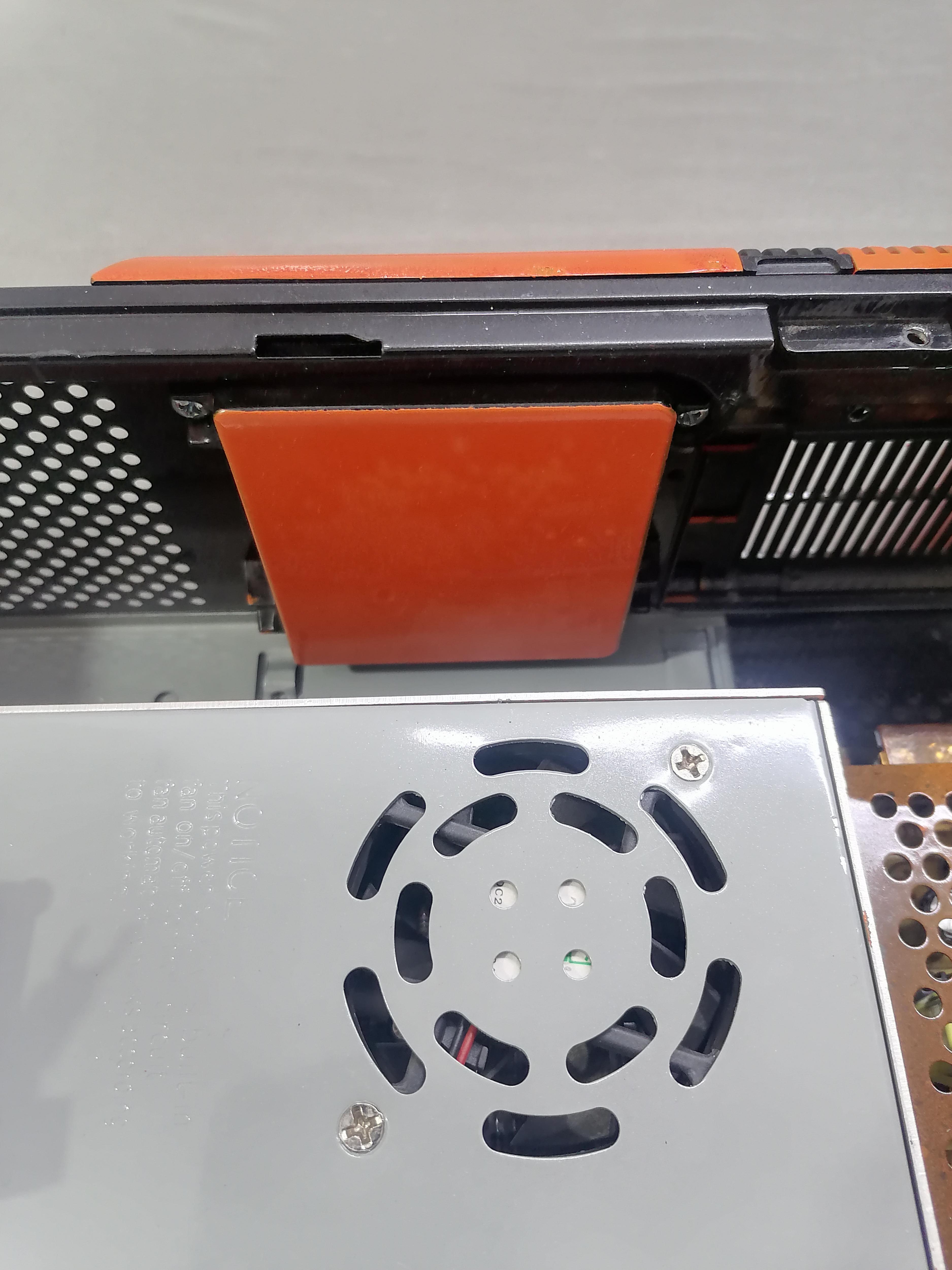
Remove and Open Power Supply of 3D Printer
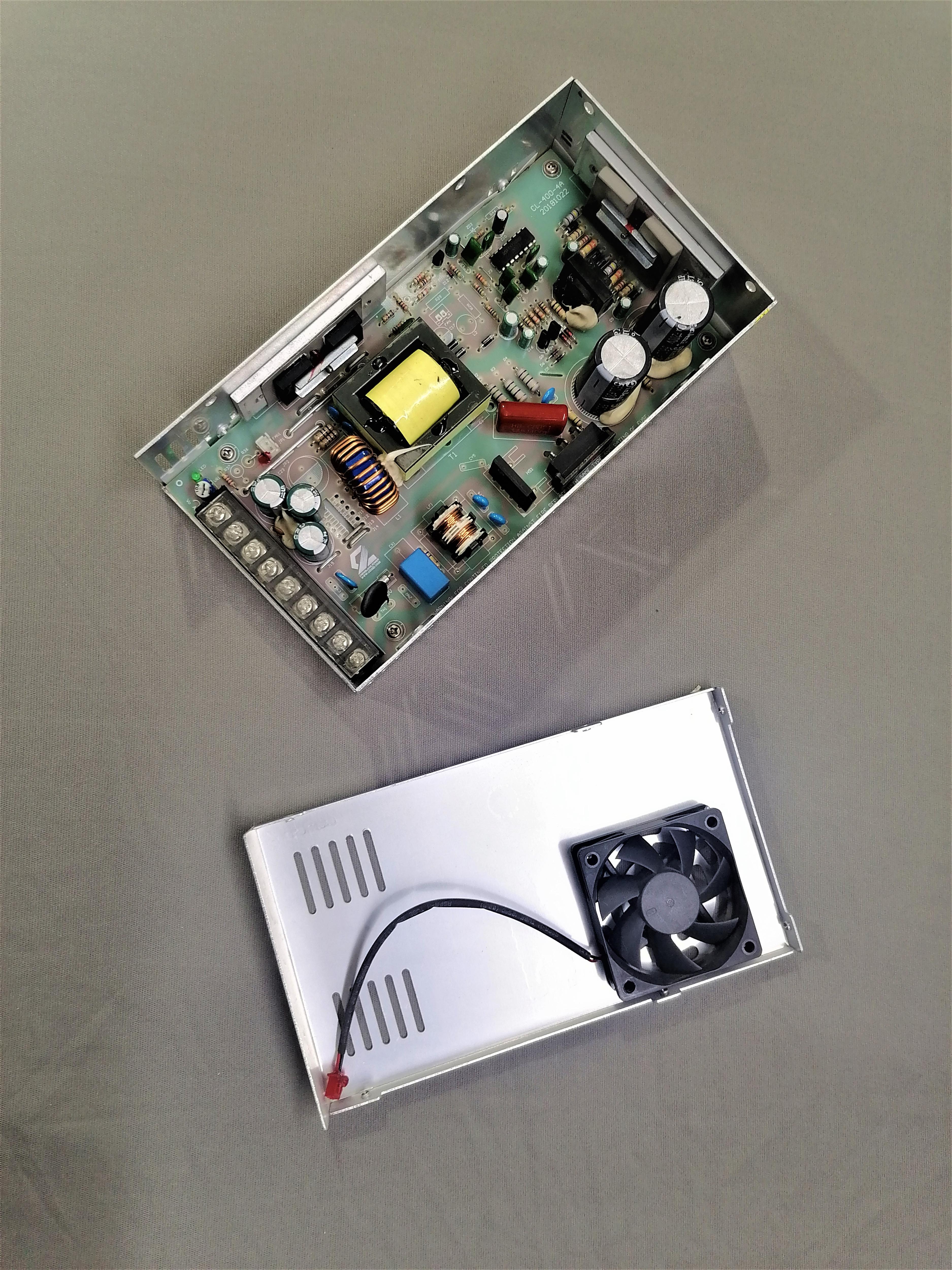
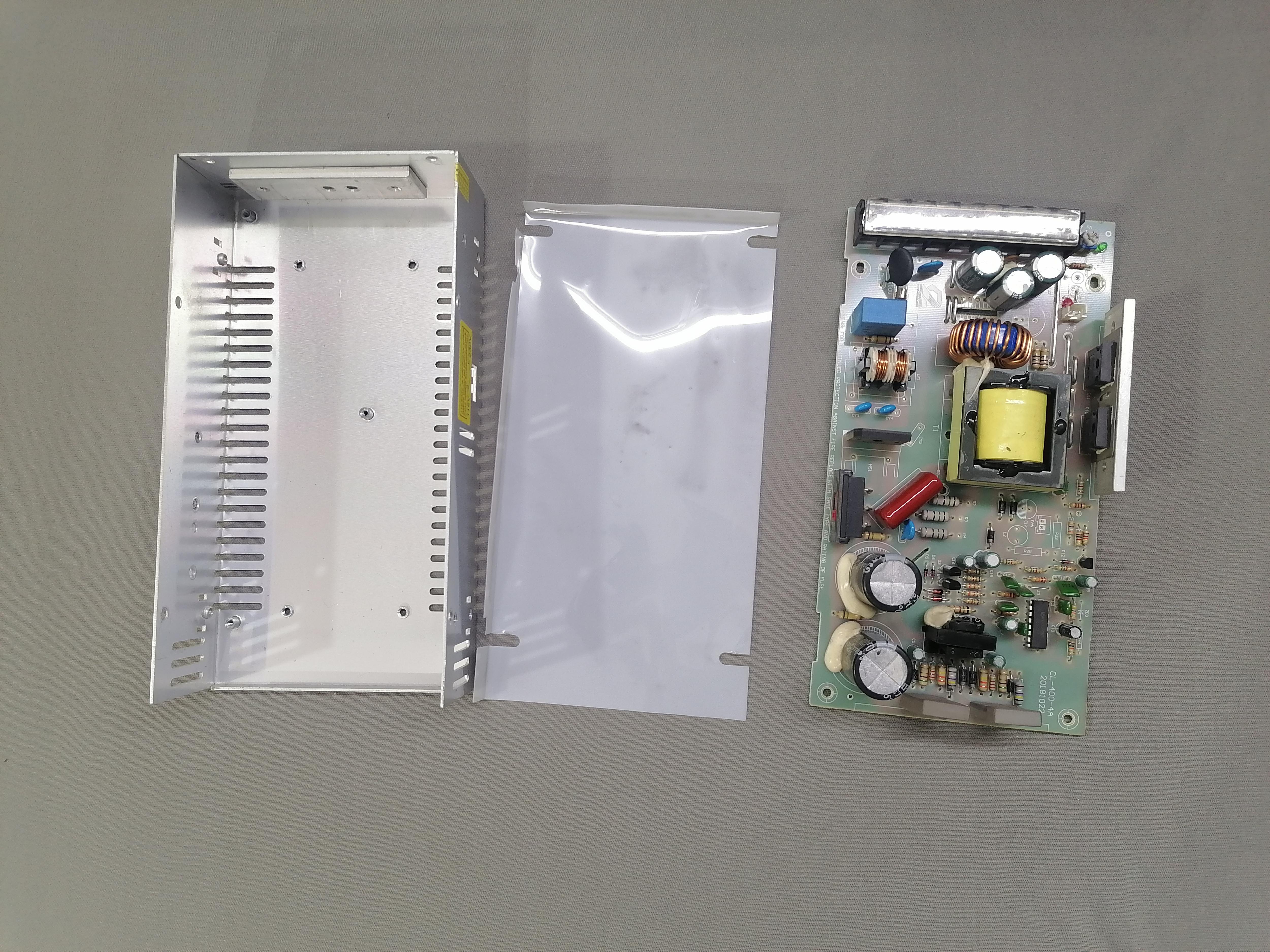
Remove the power supply from the 3D printer, open it and clean all dust from components.
Note: Do not close it.
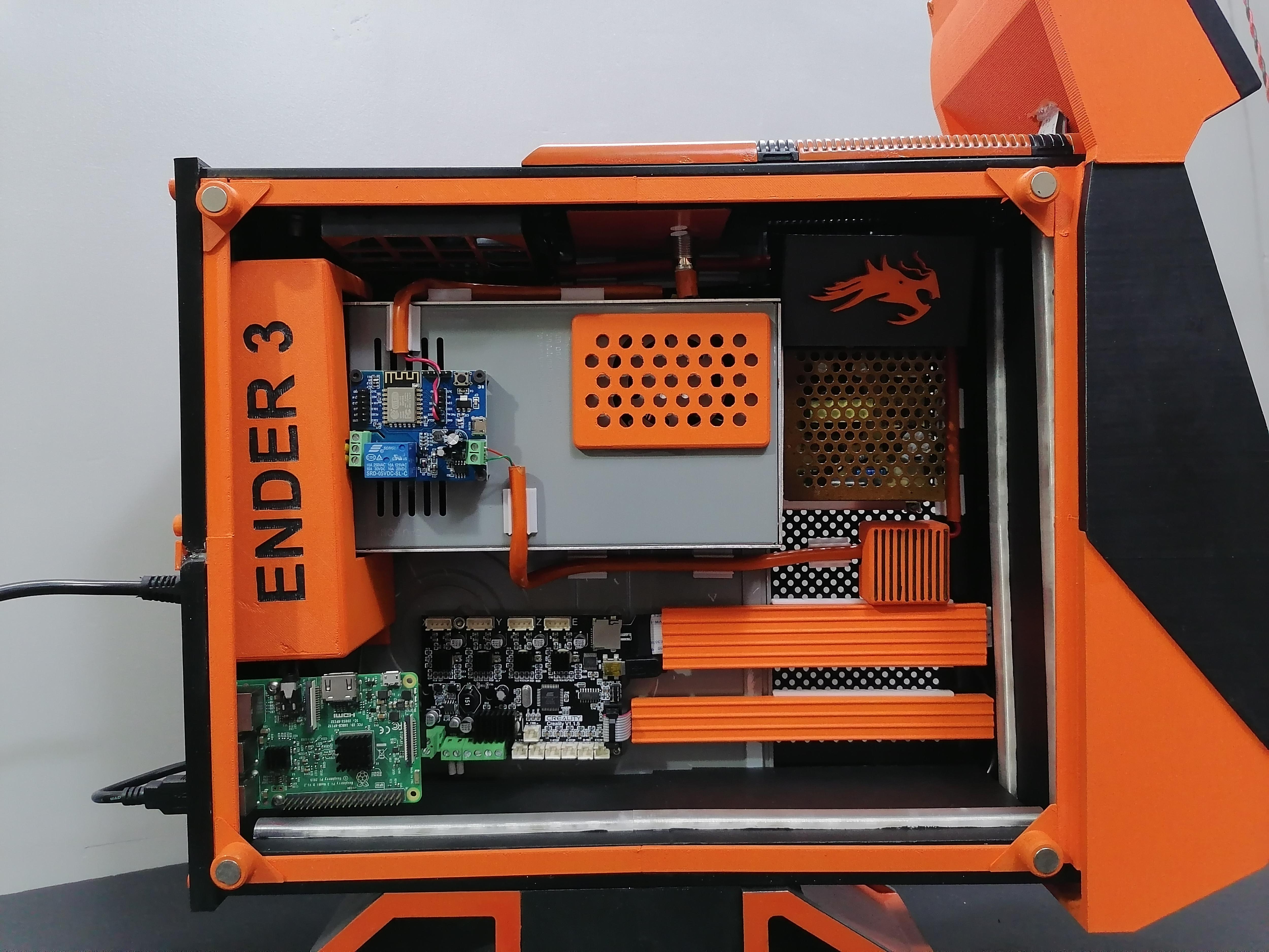
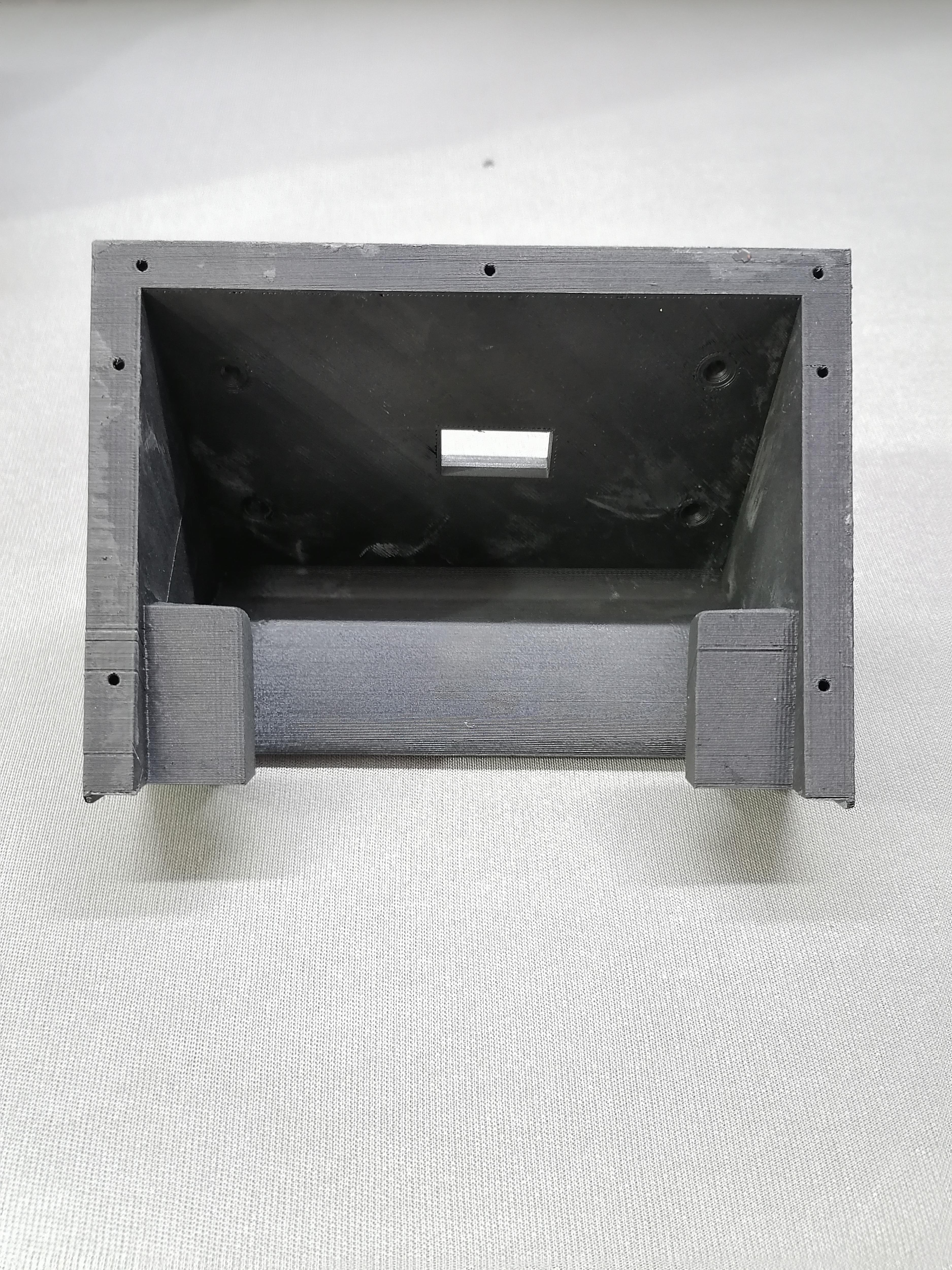
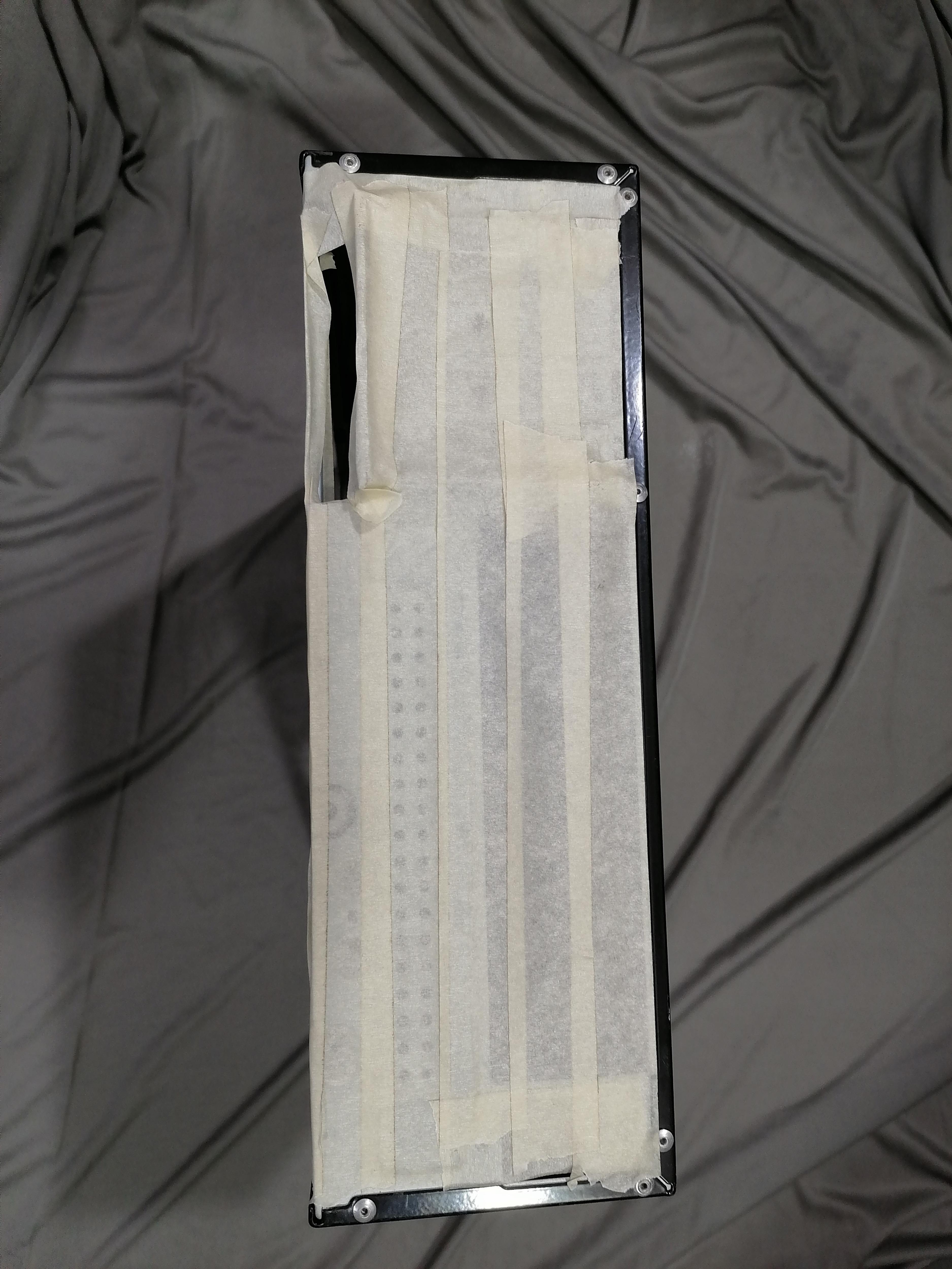
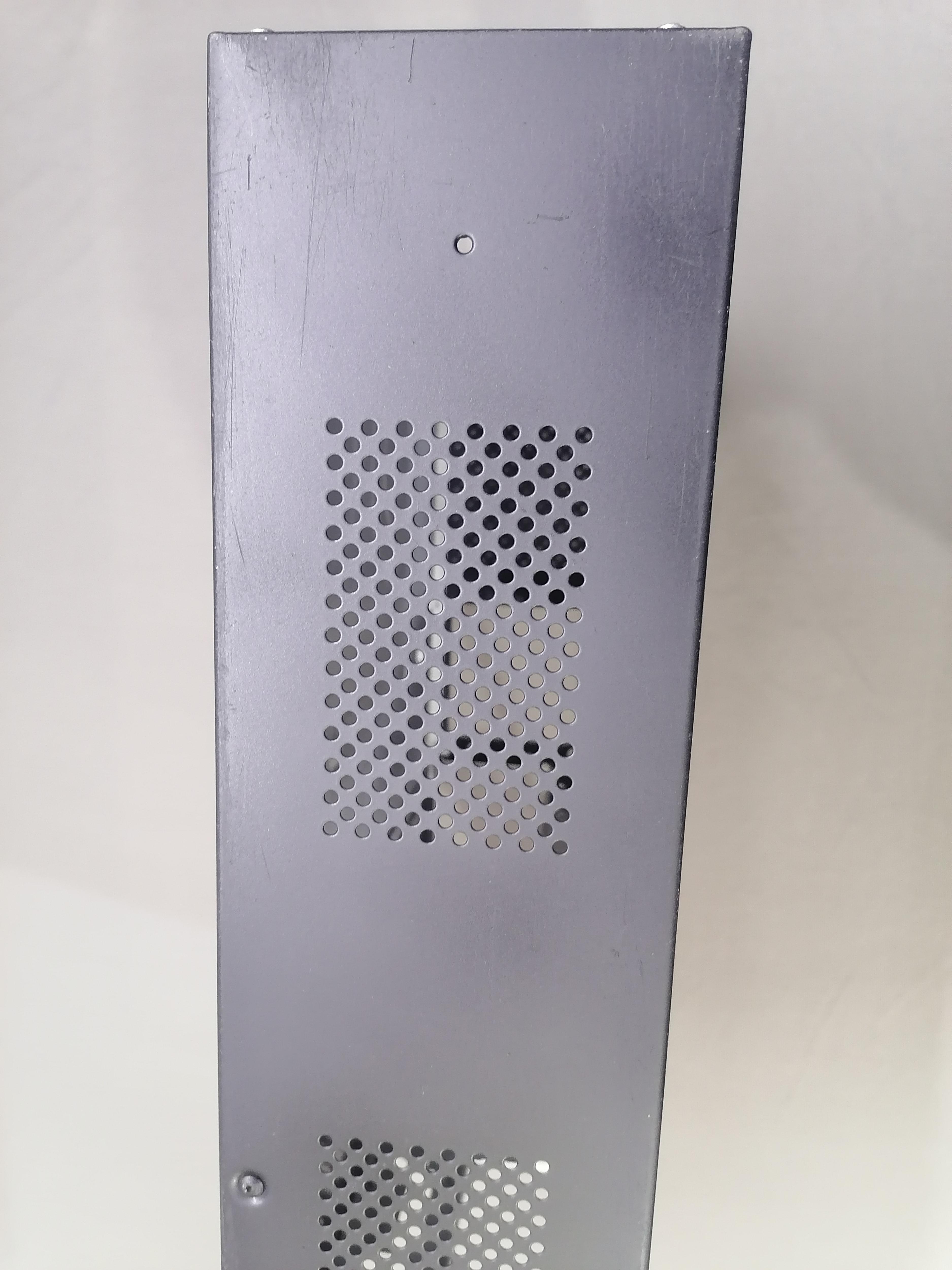
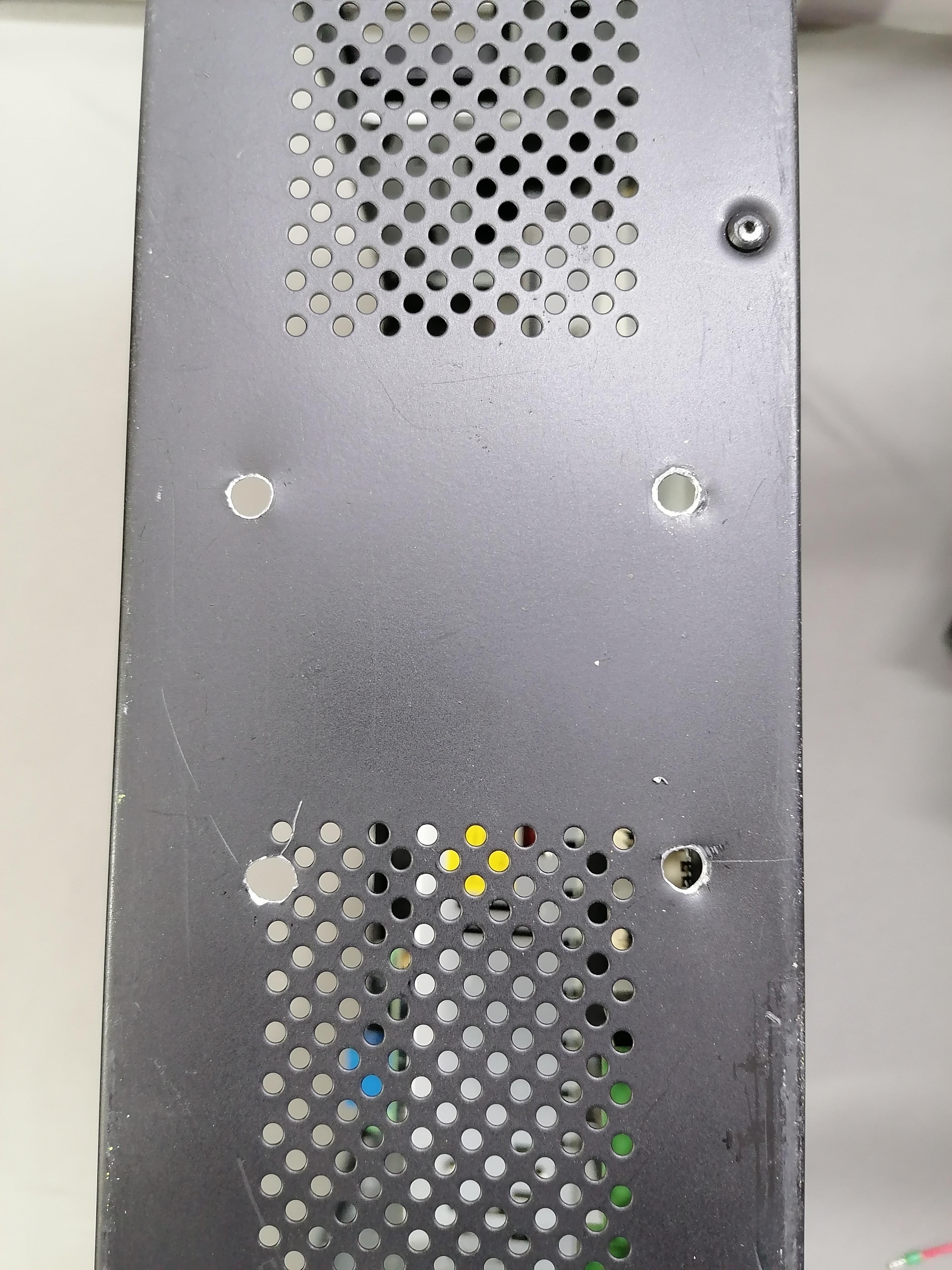
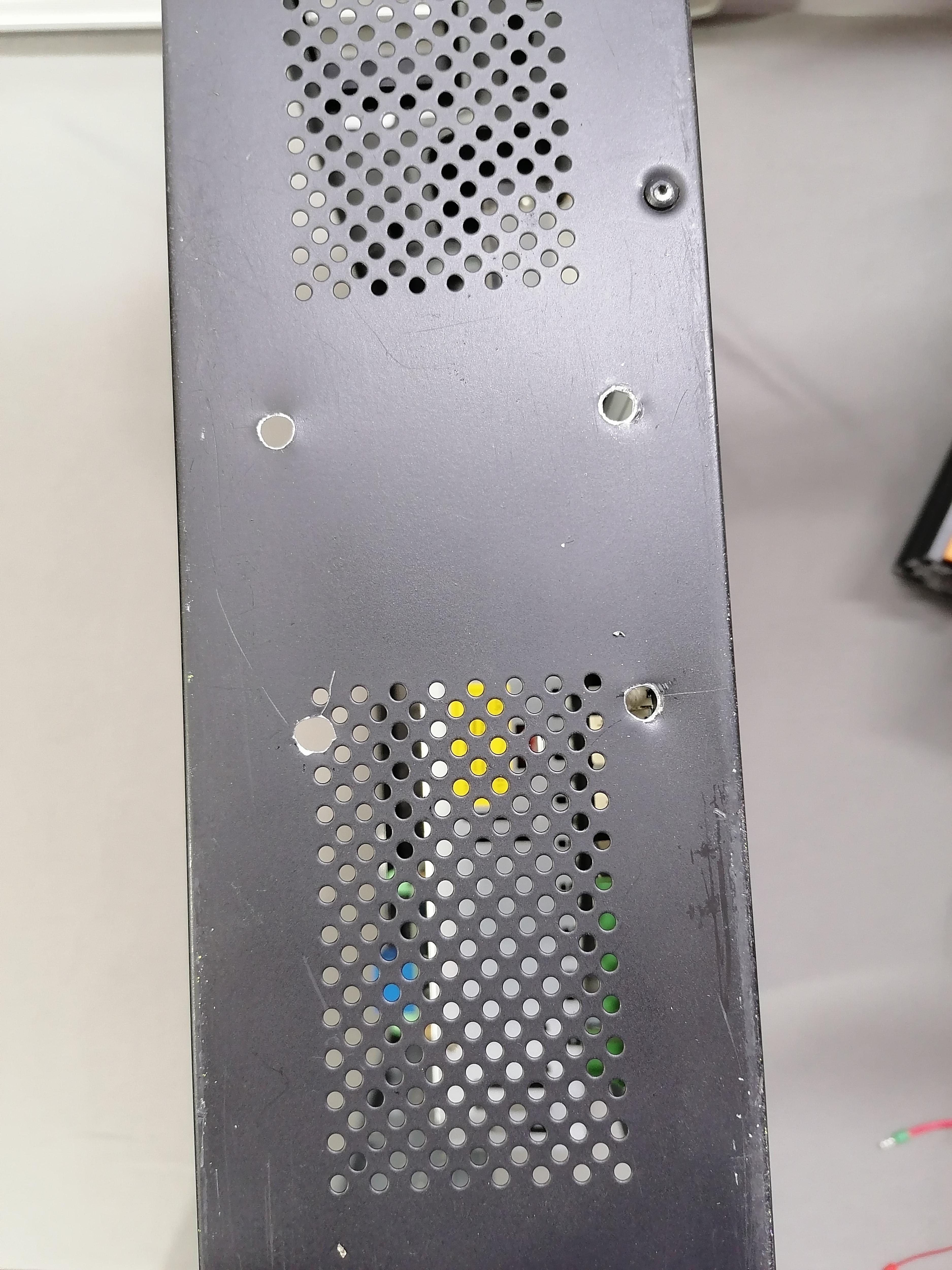
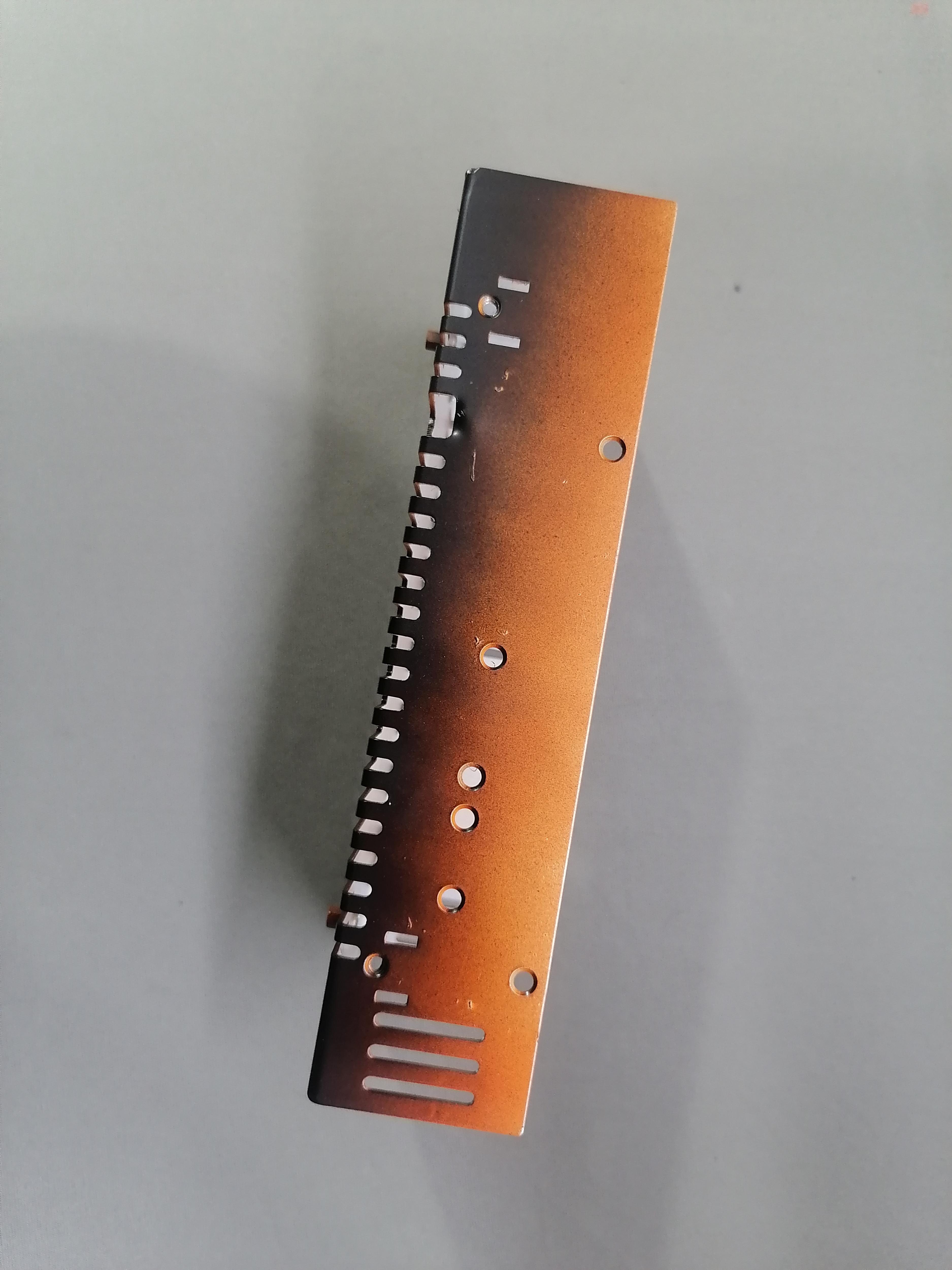
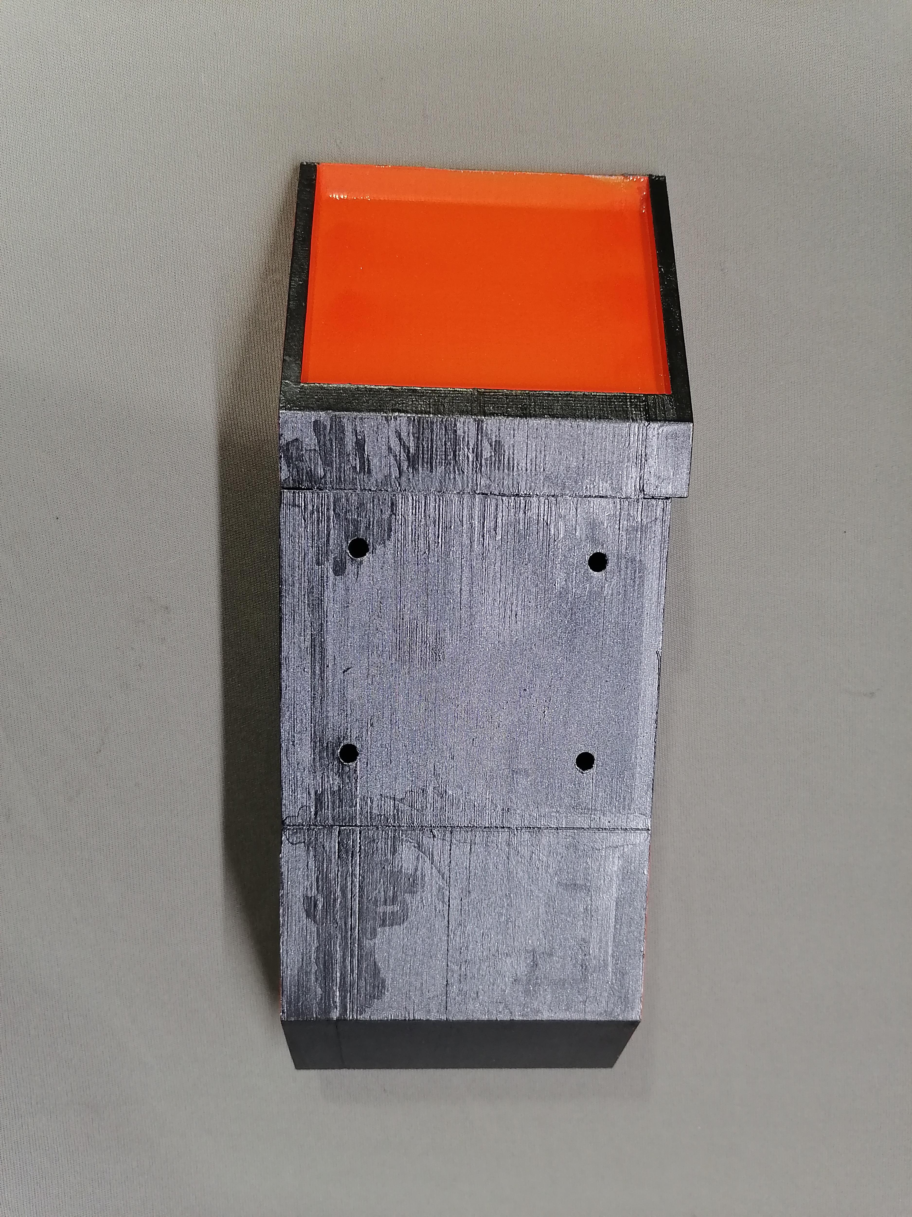
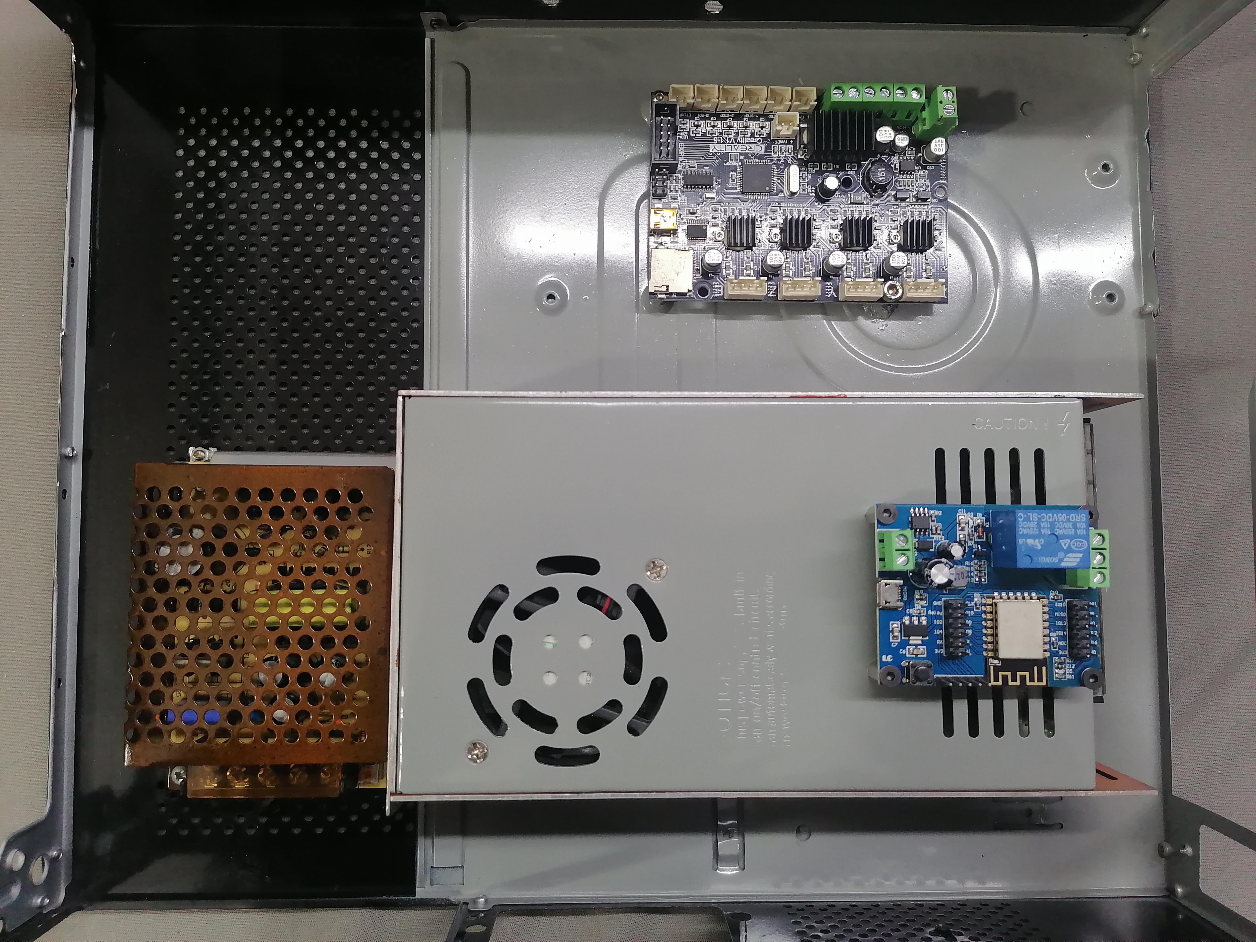
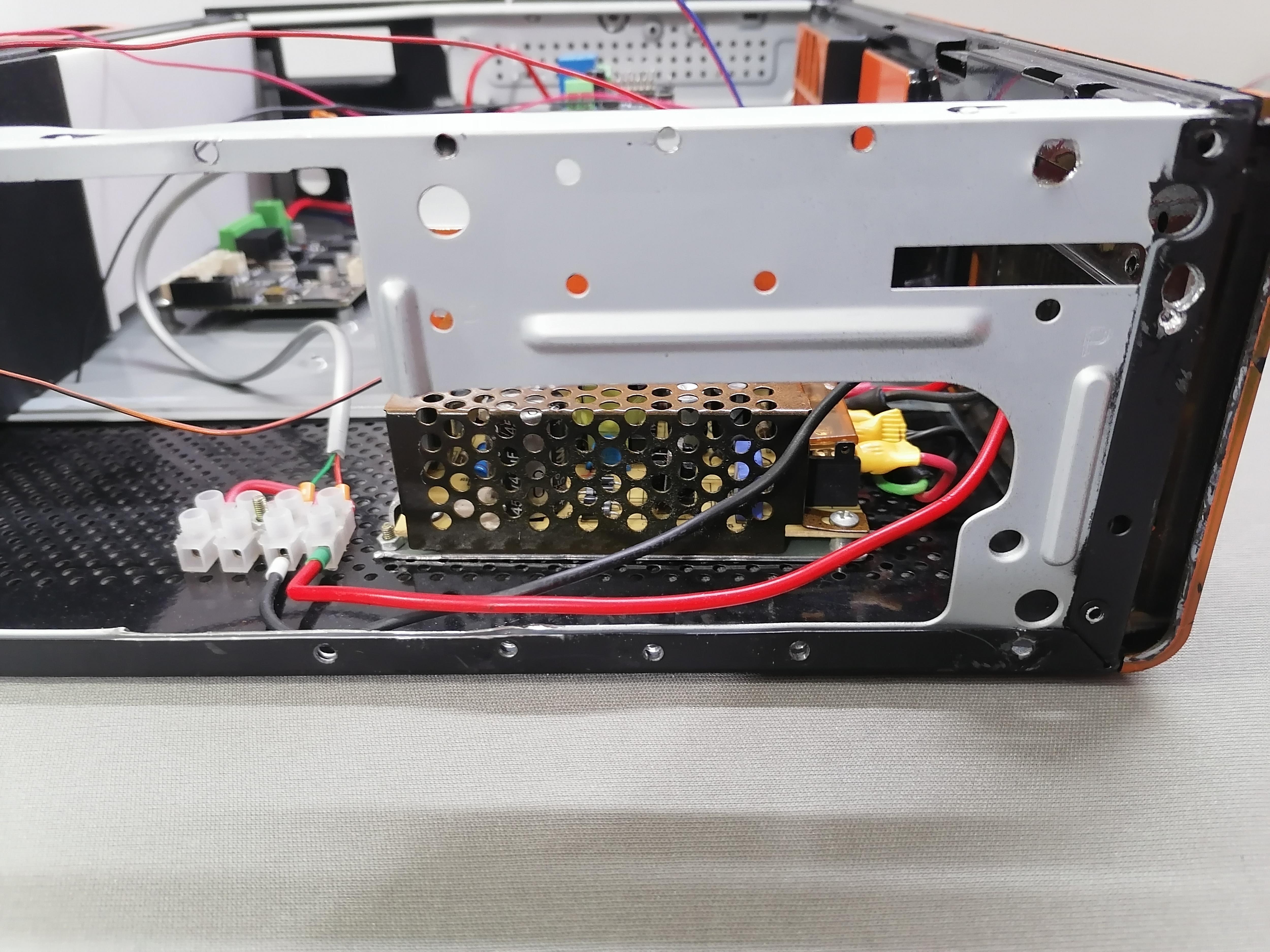
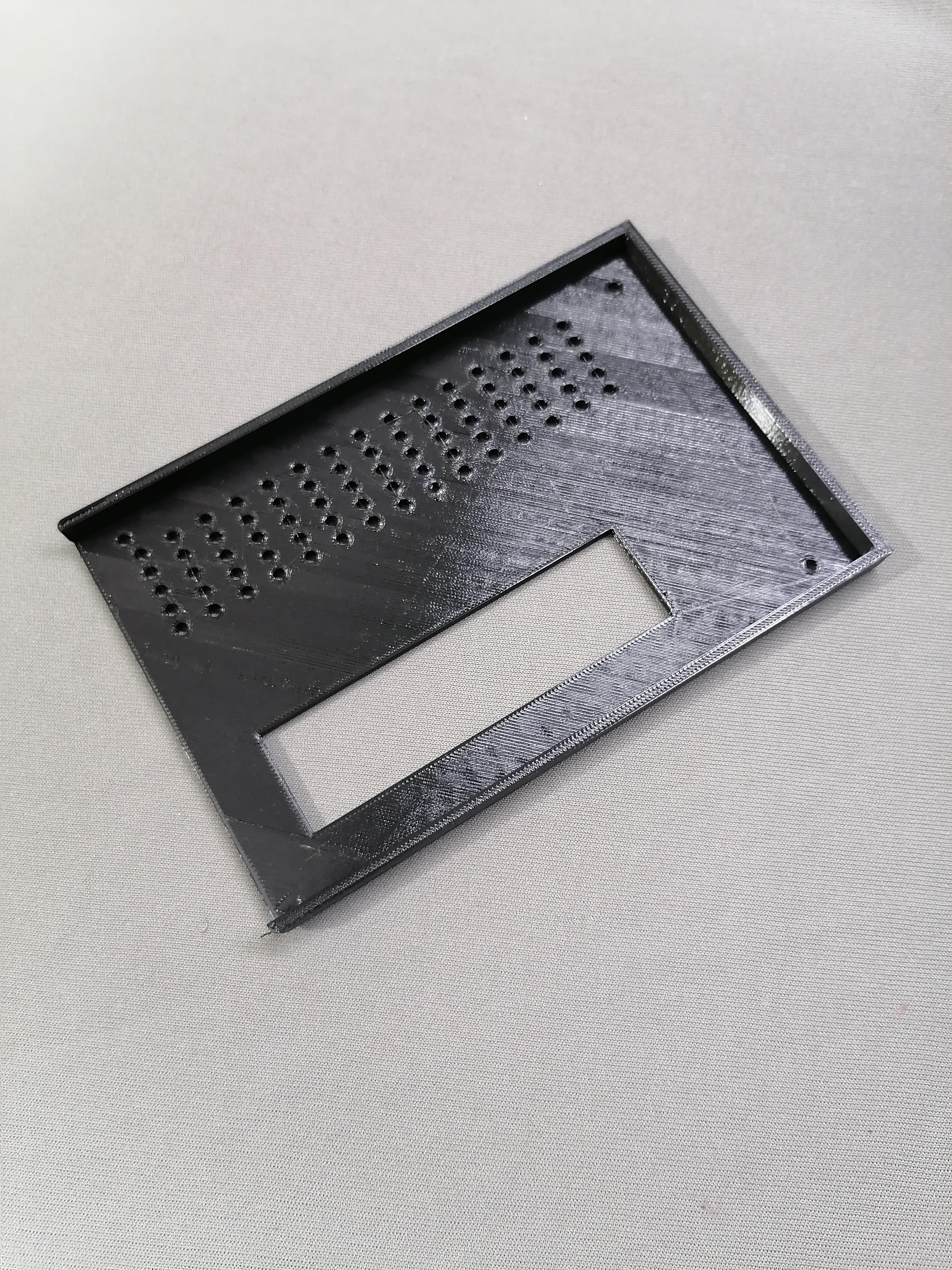
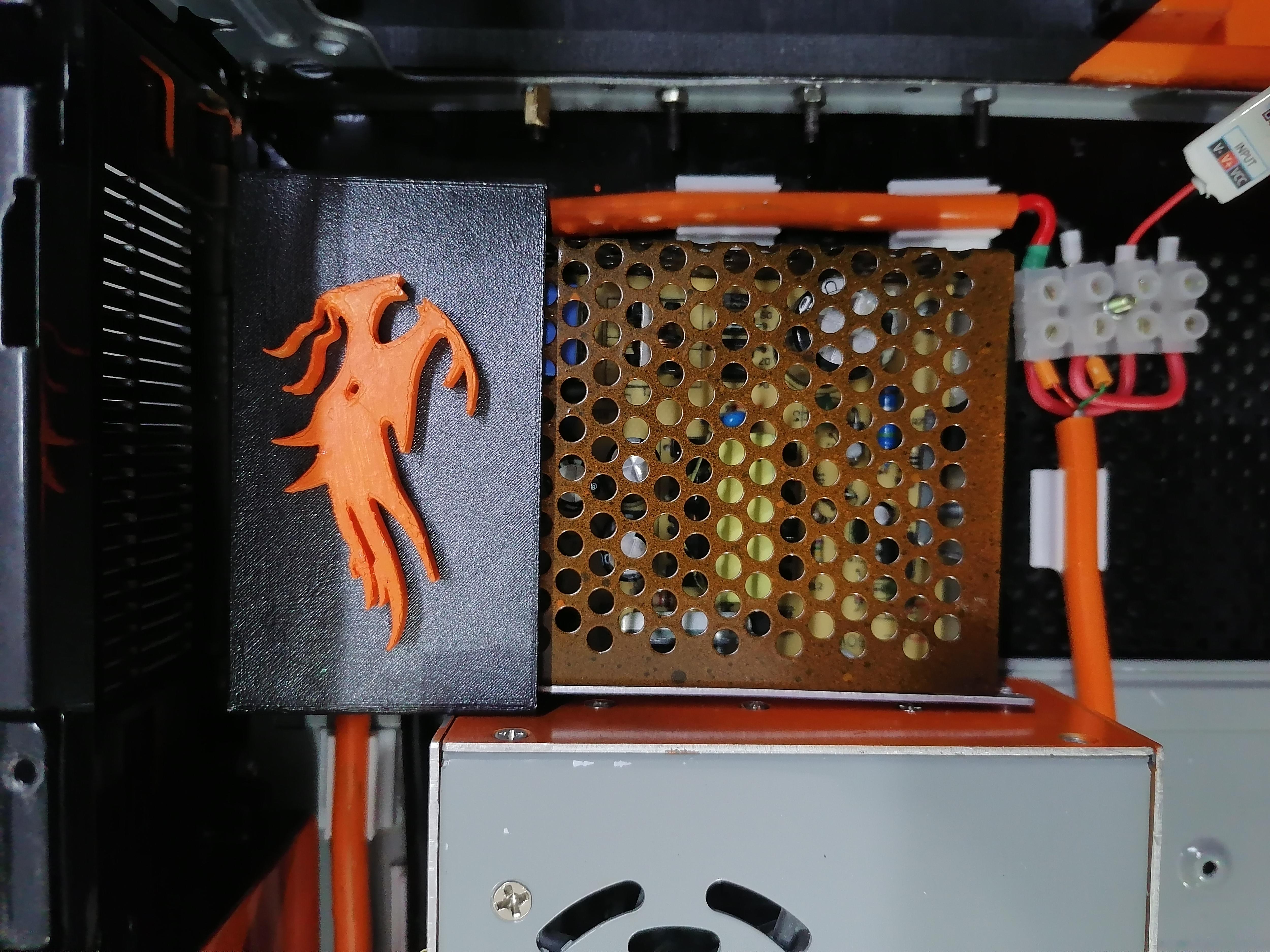
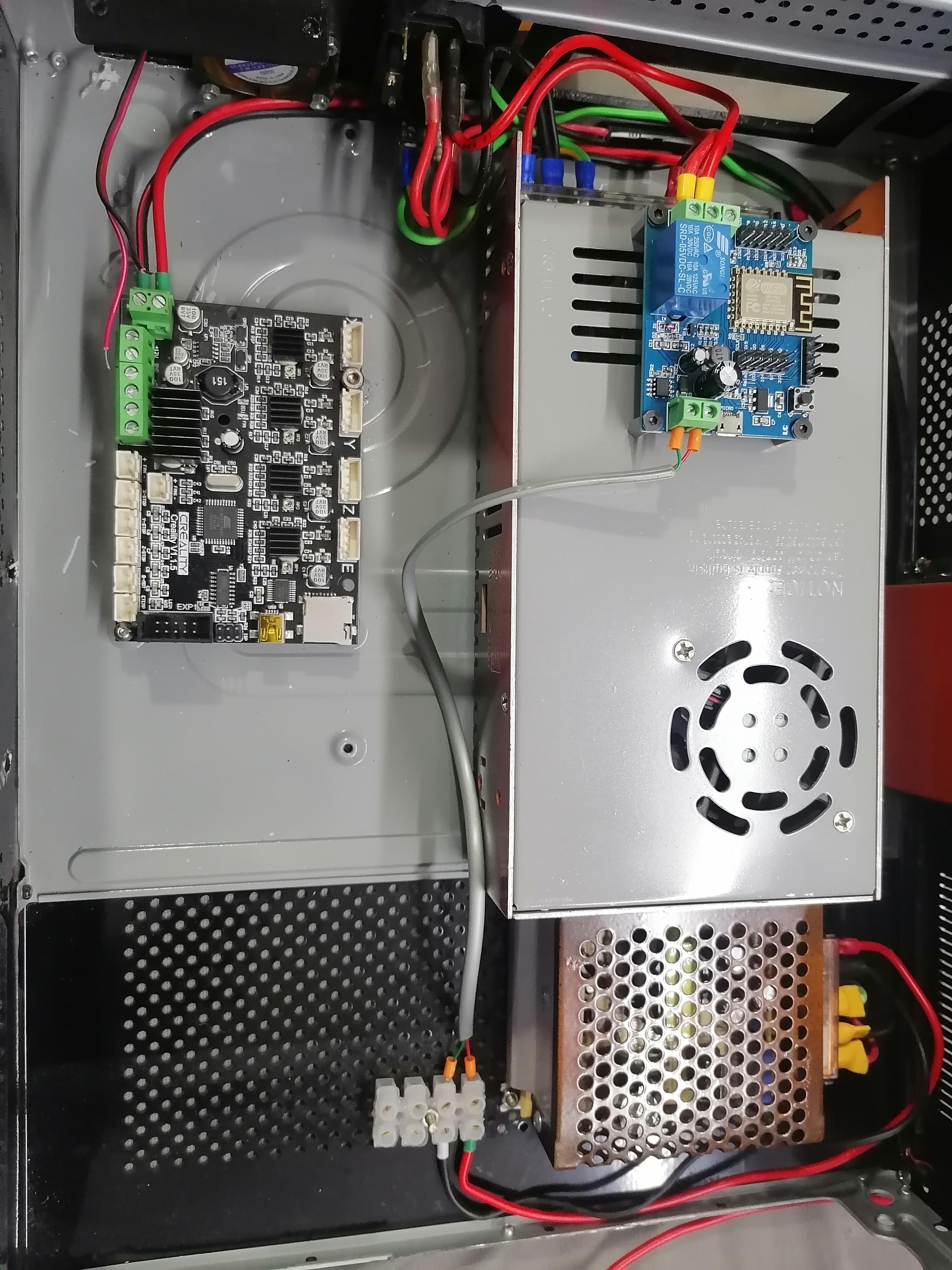
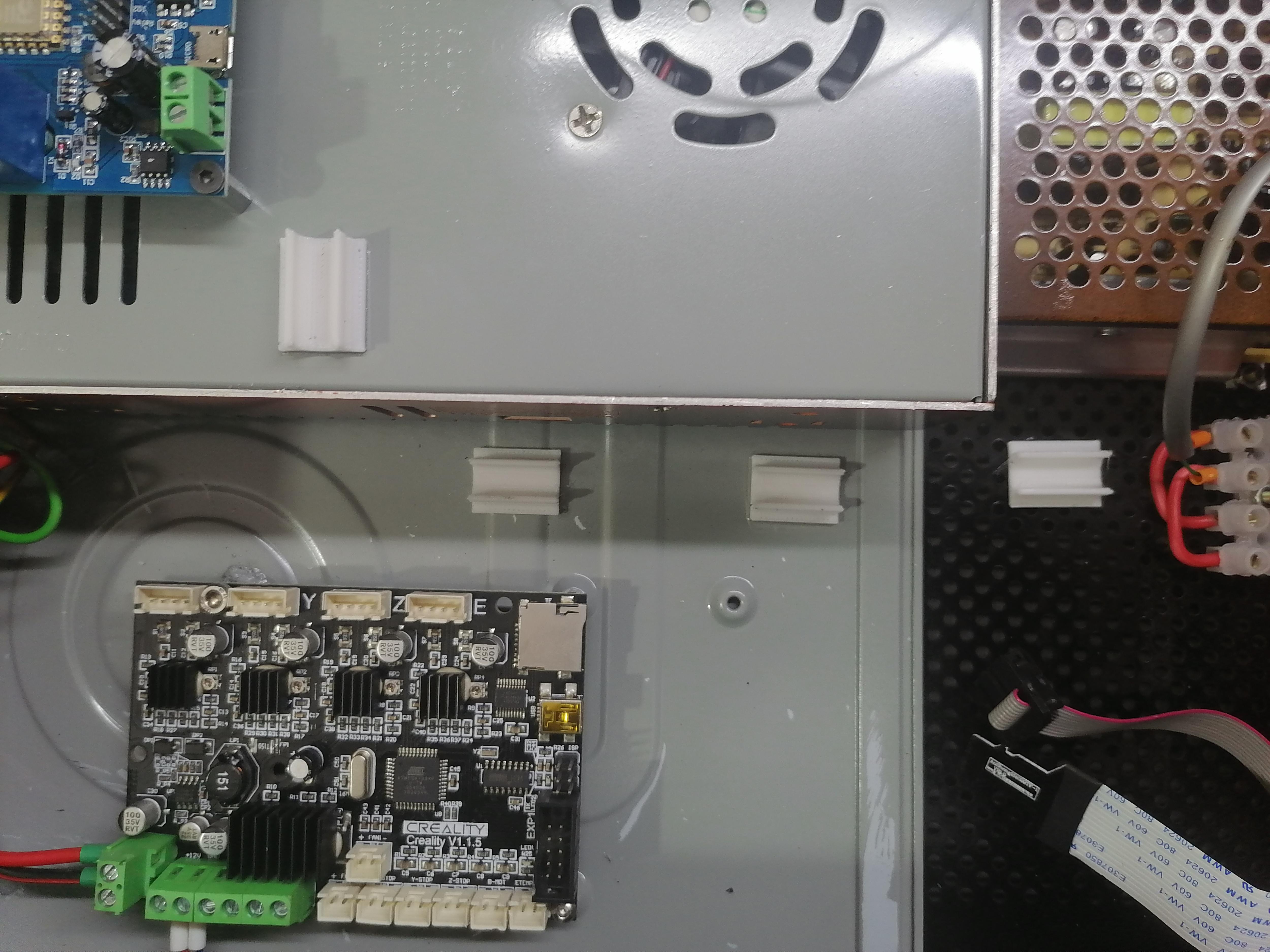
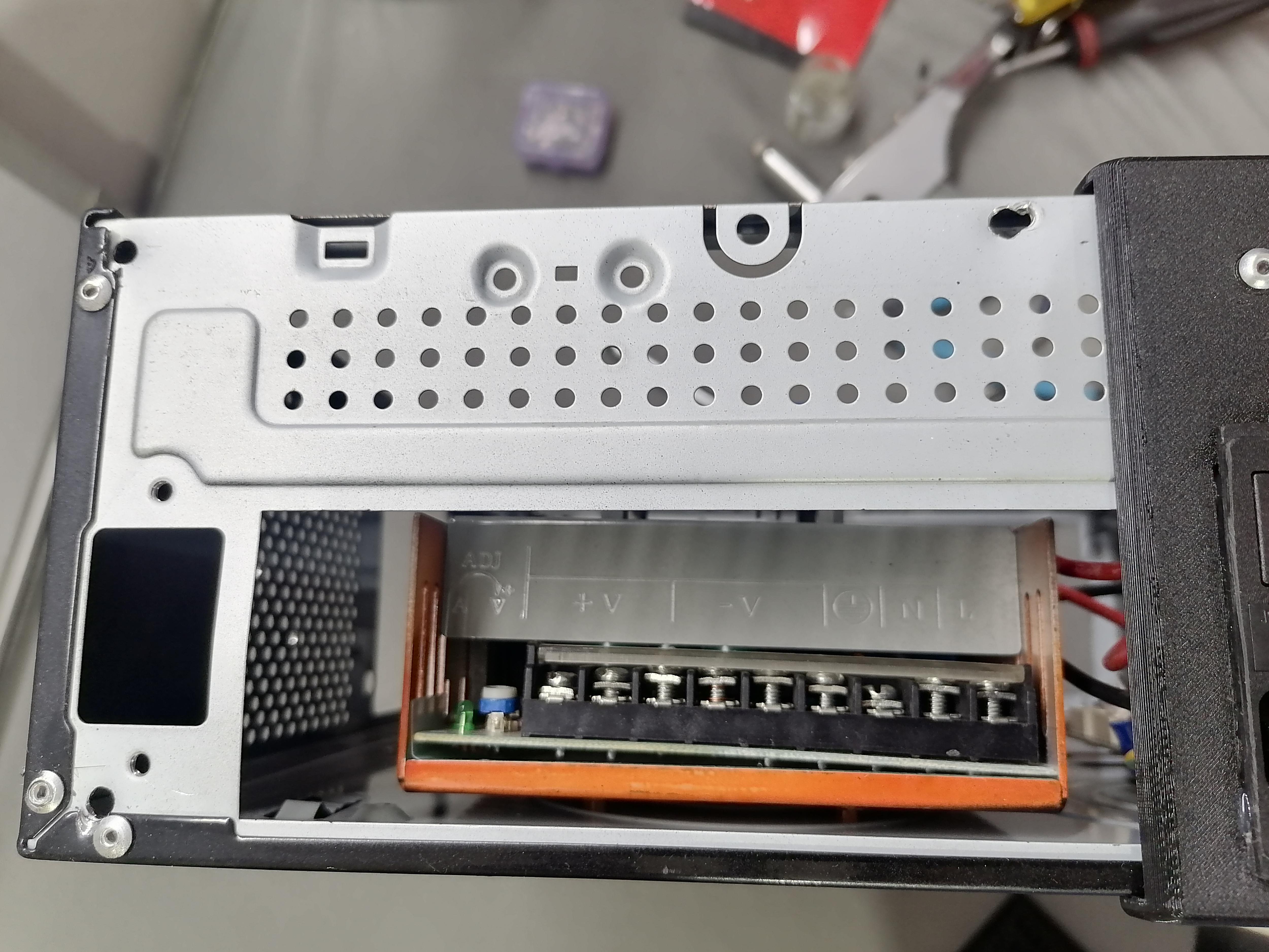
Holes Marking of the Power Supply and Mainboard on CPU Case
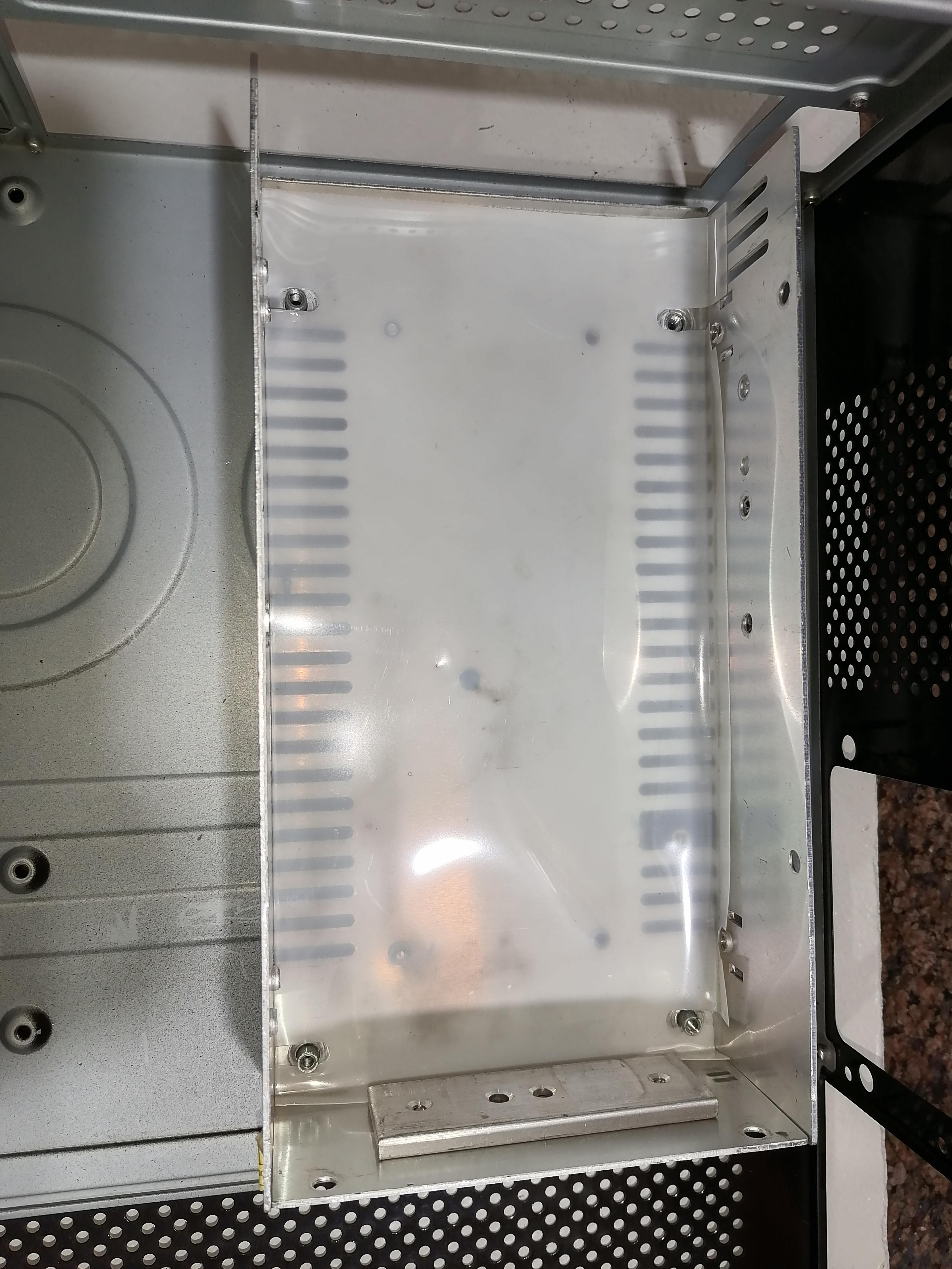
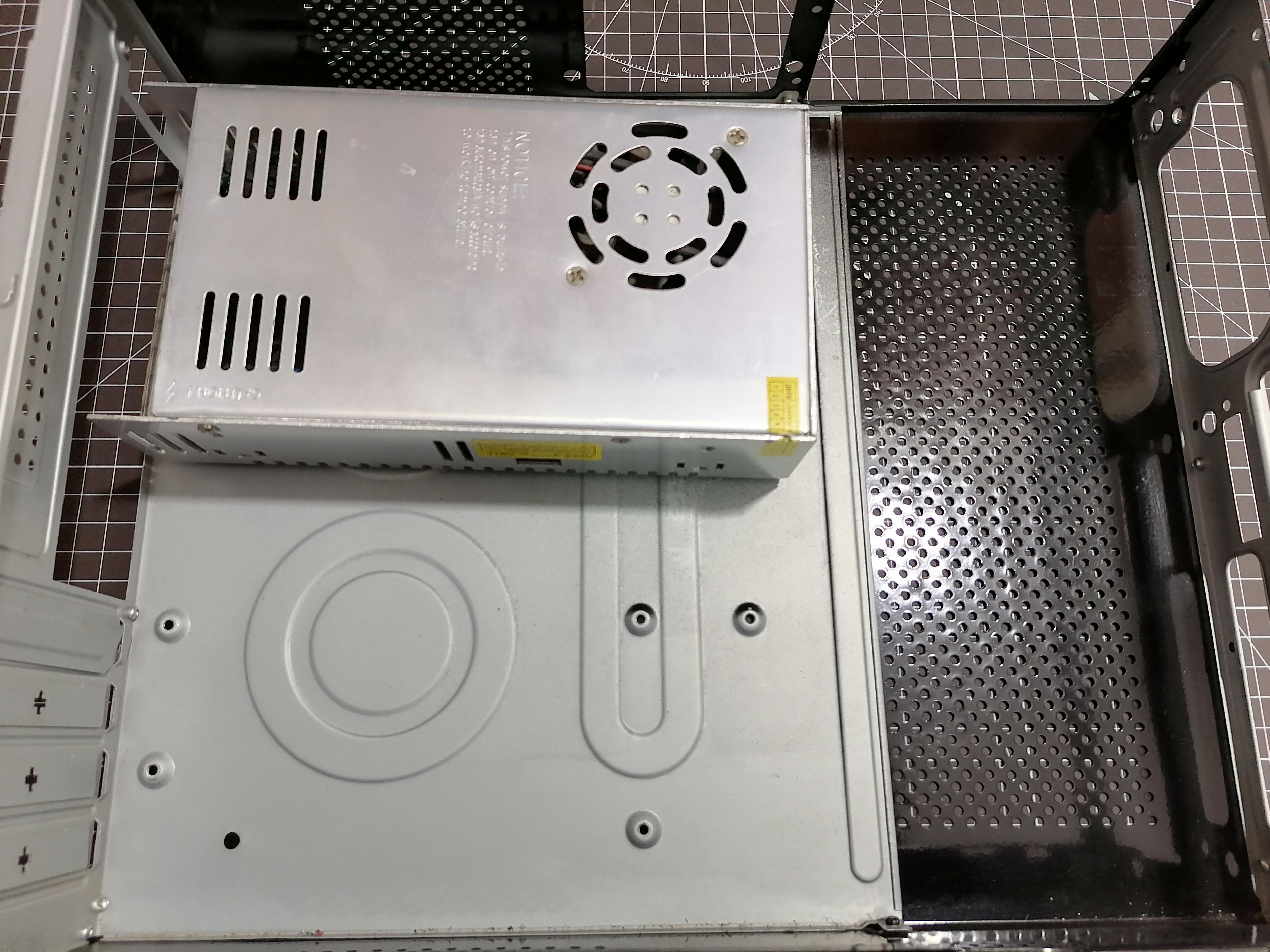
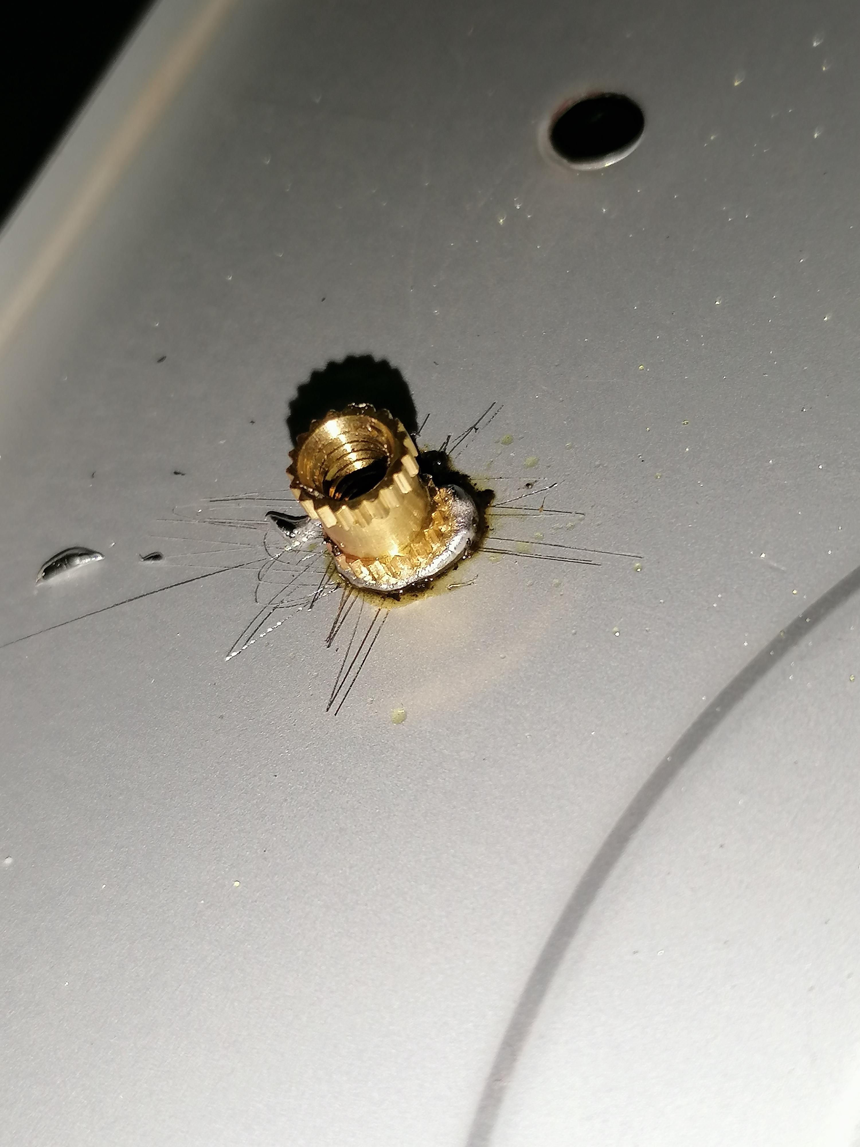

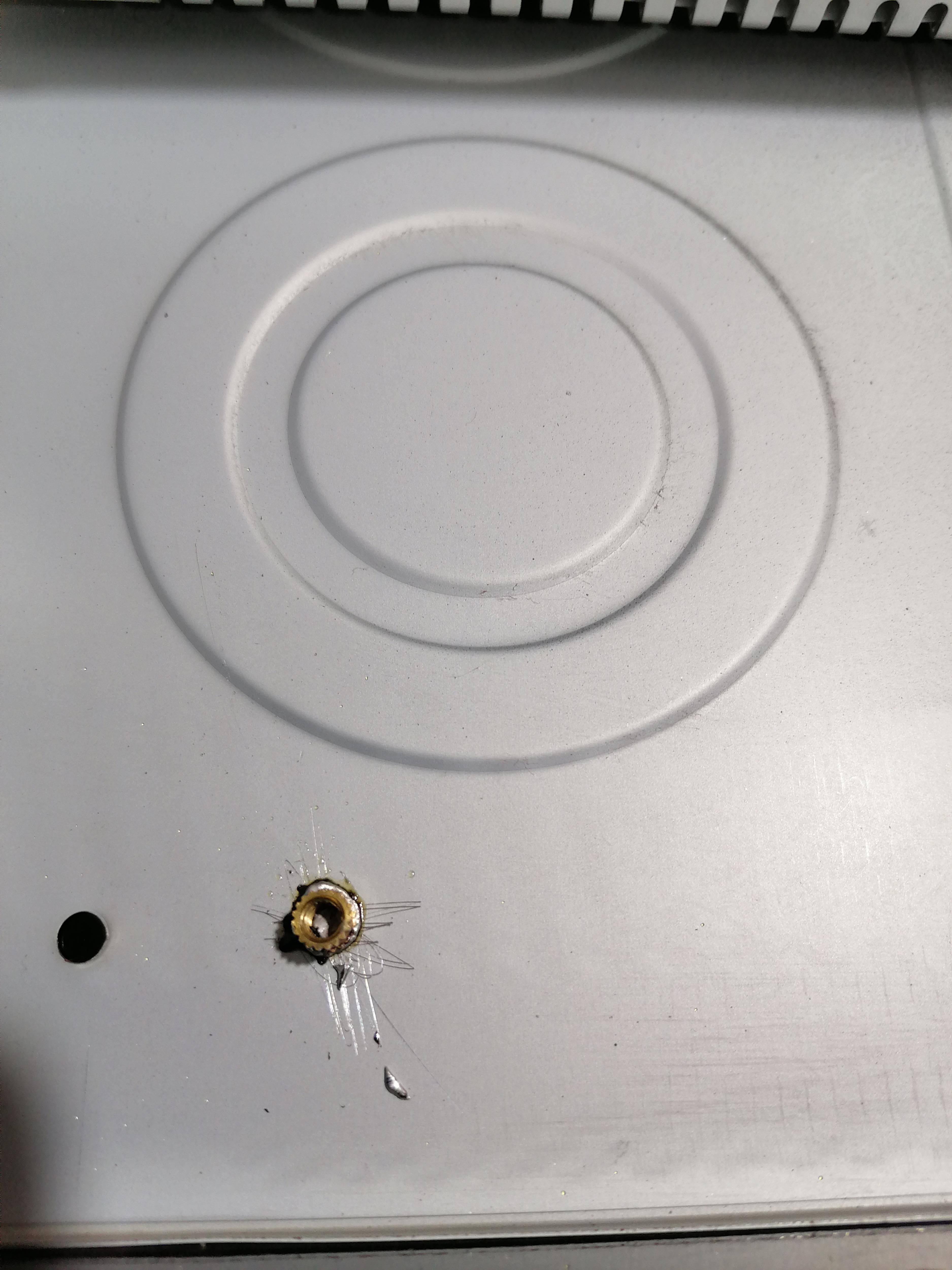
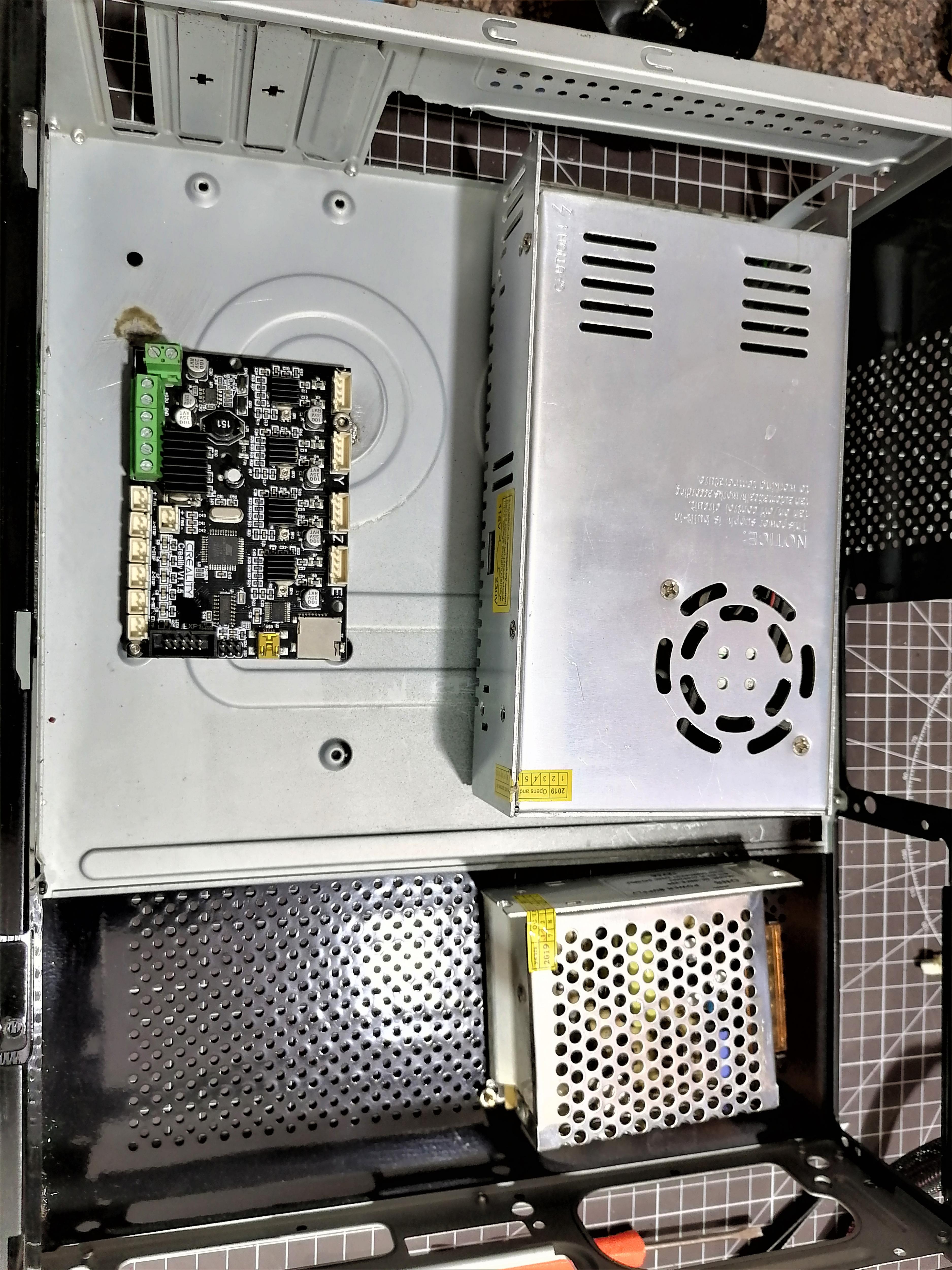
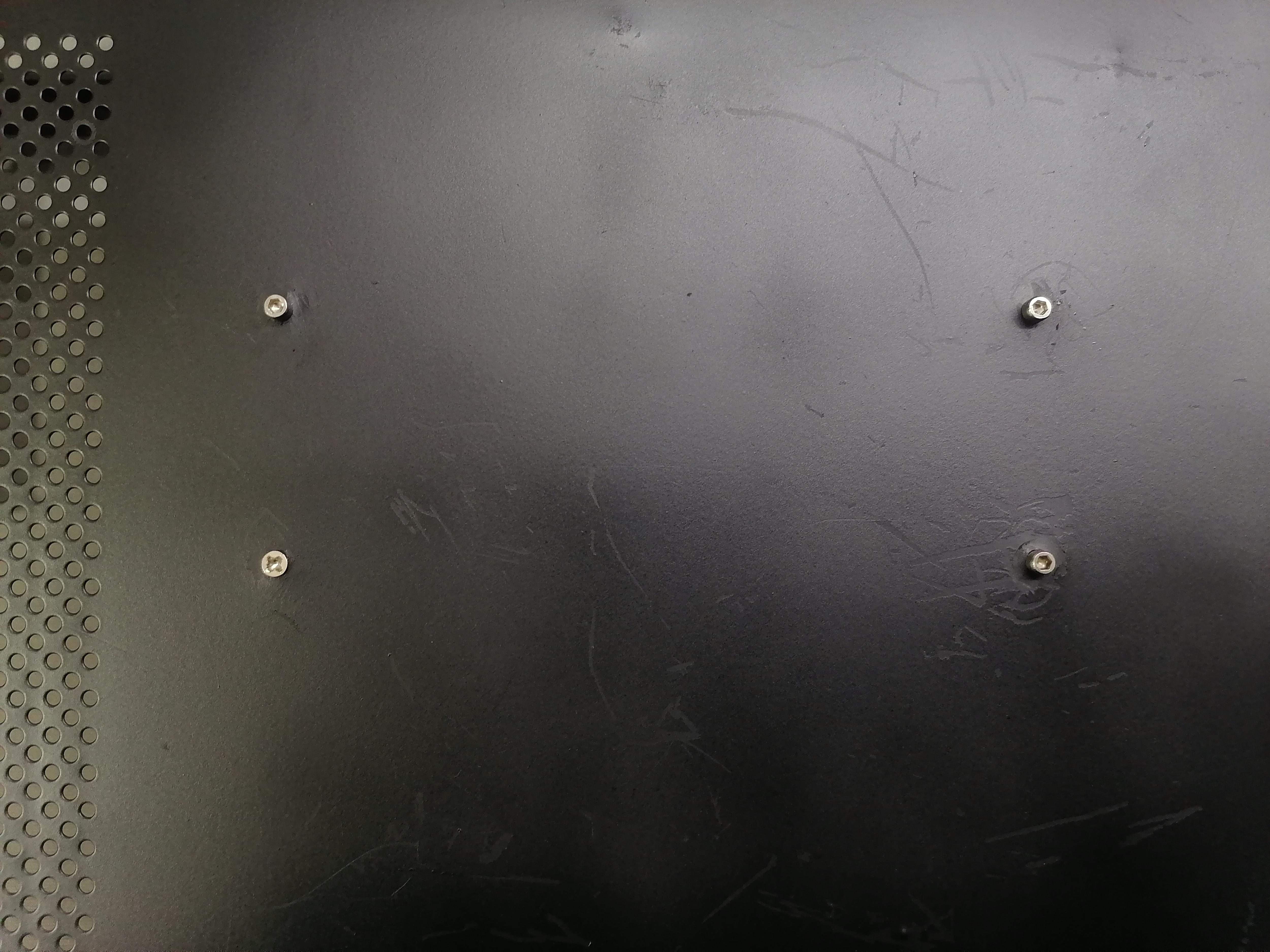
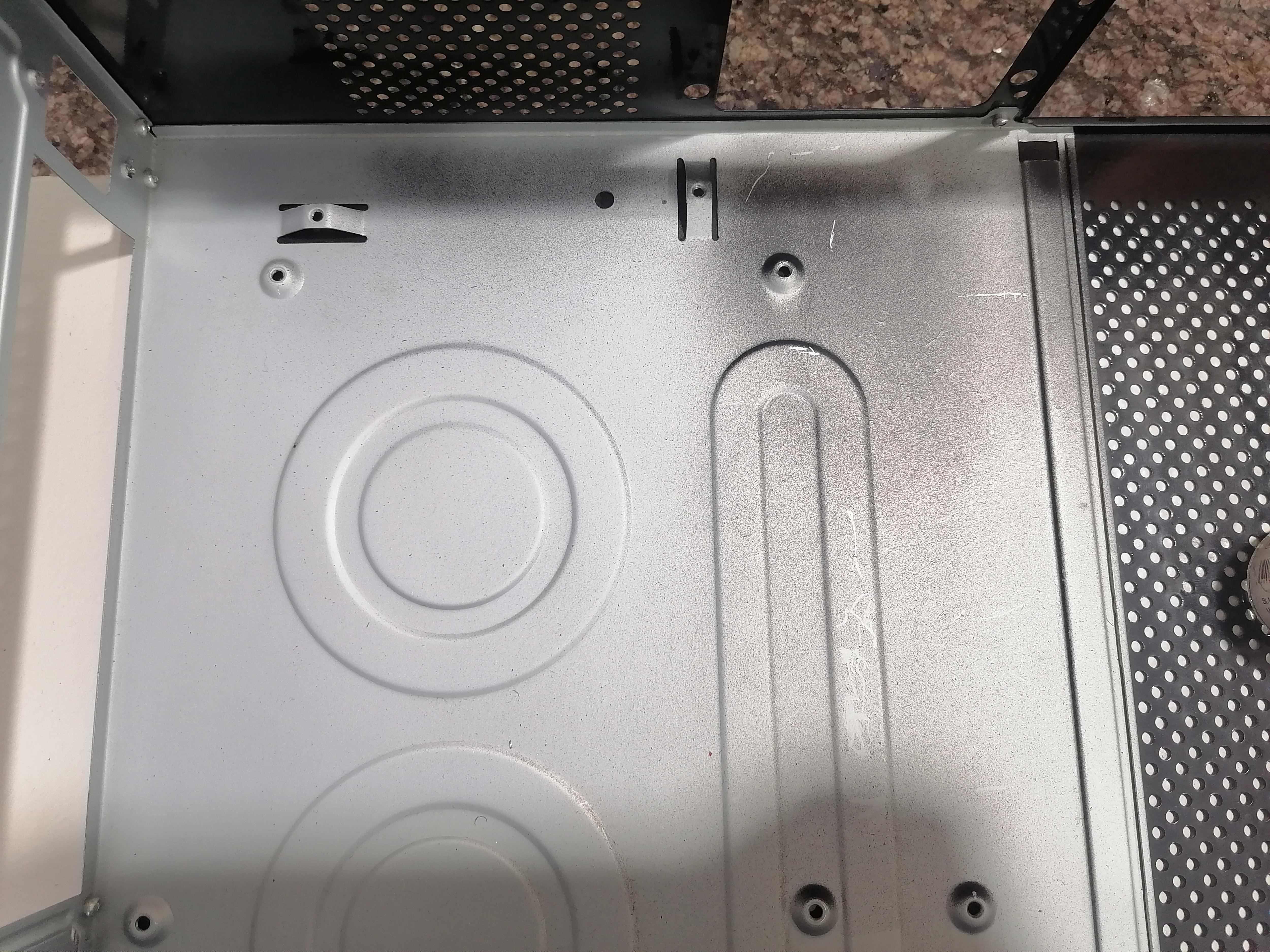
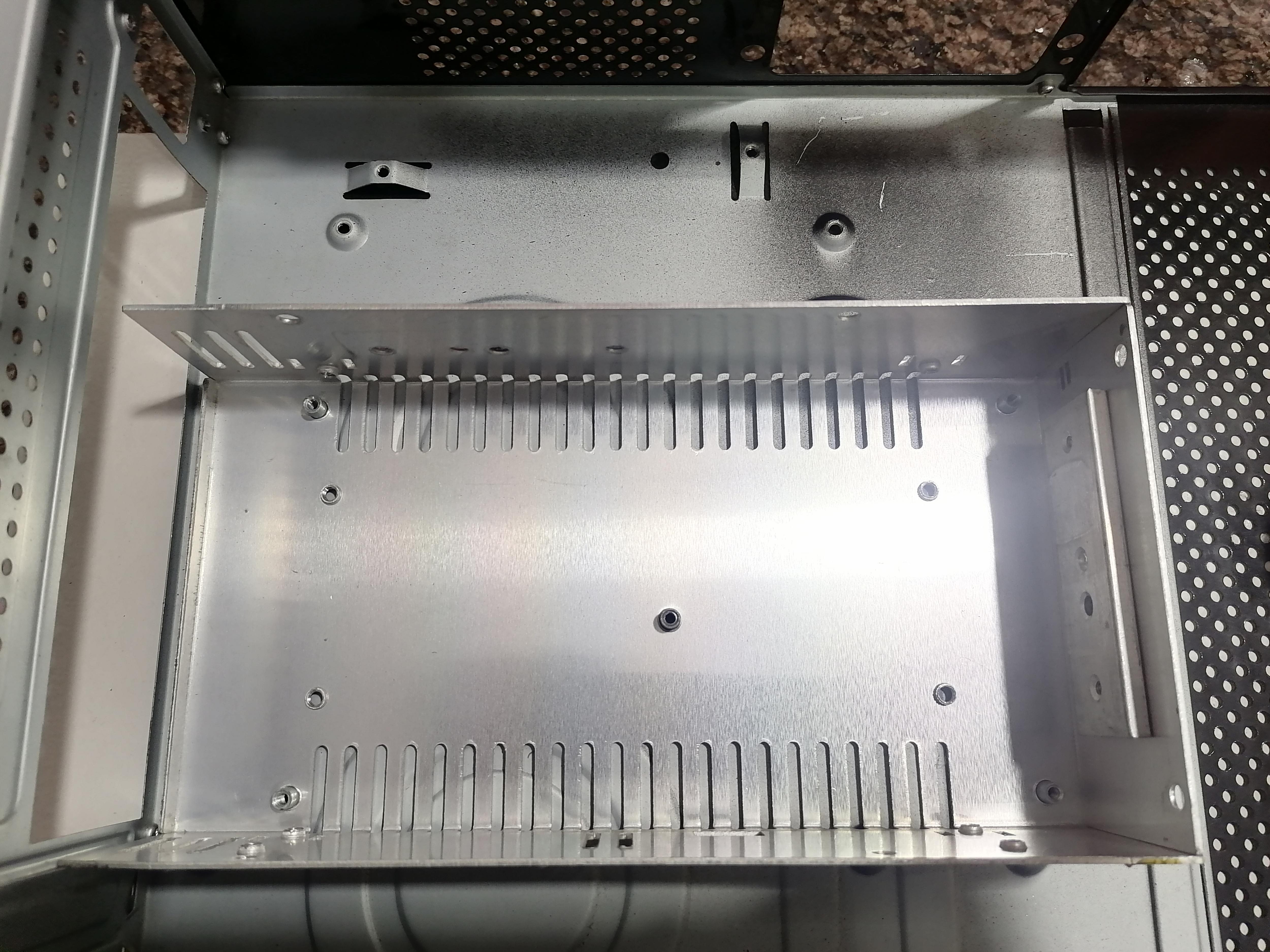
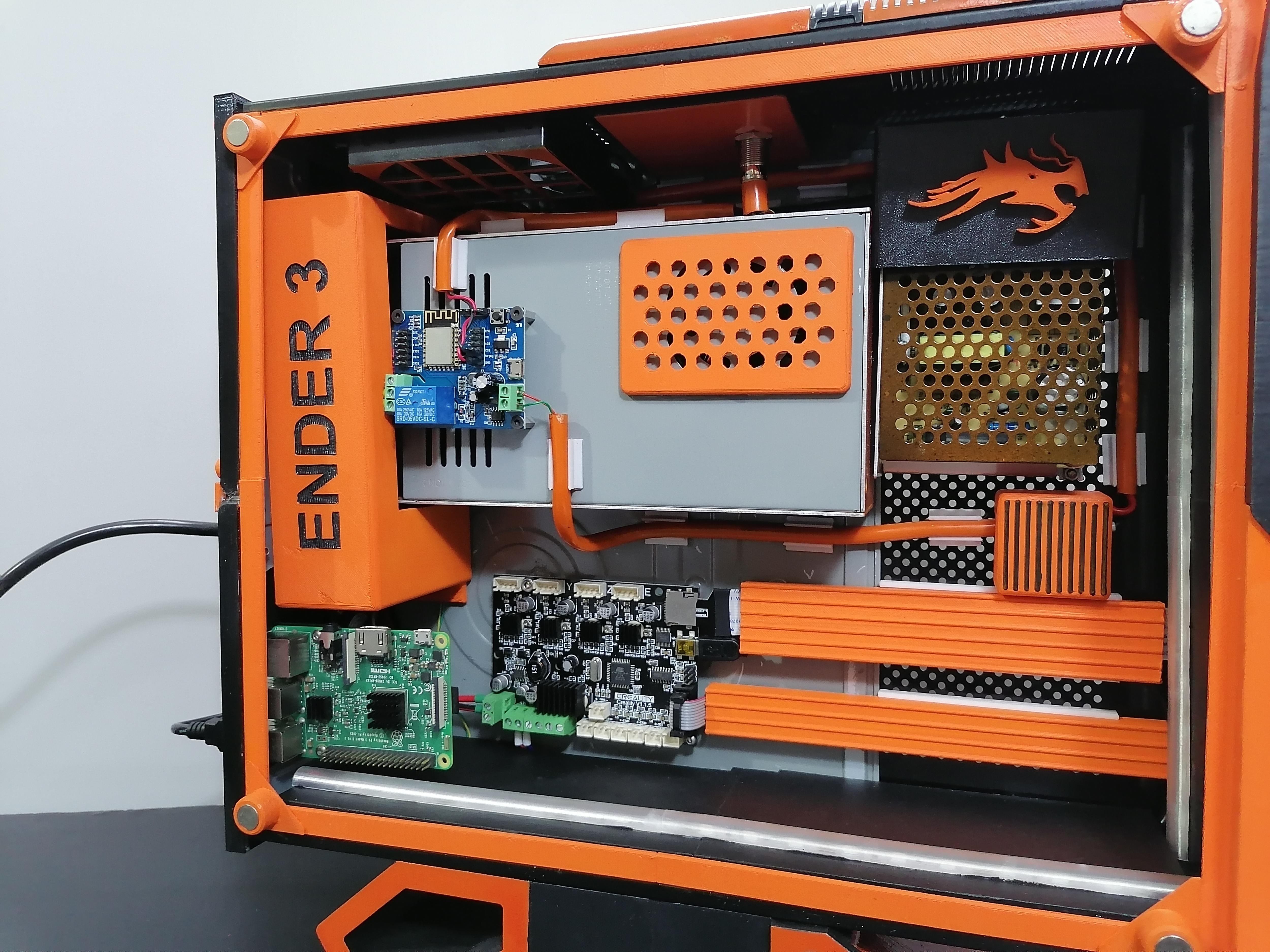
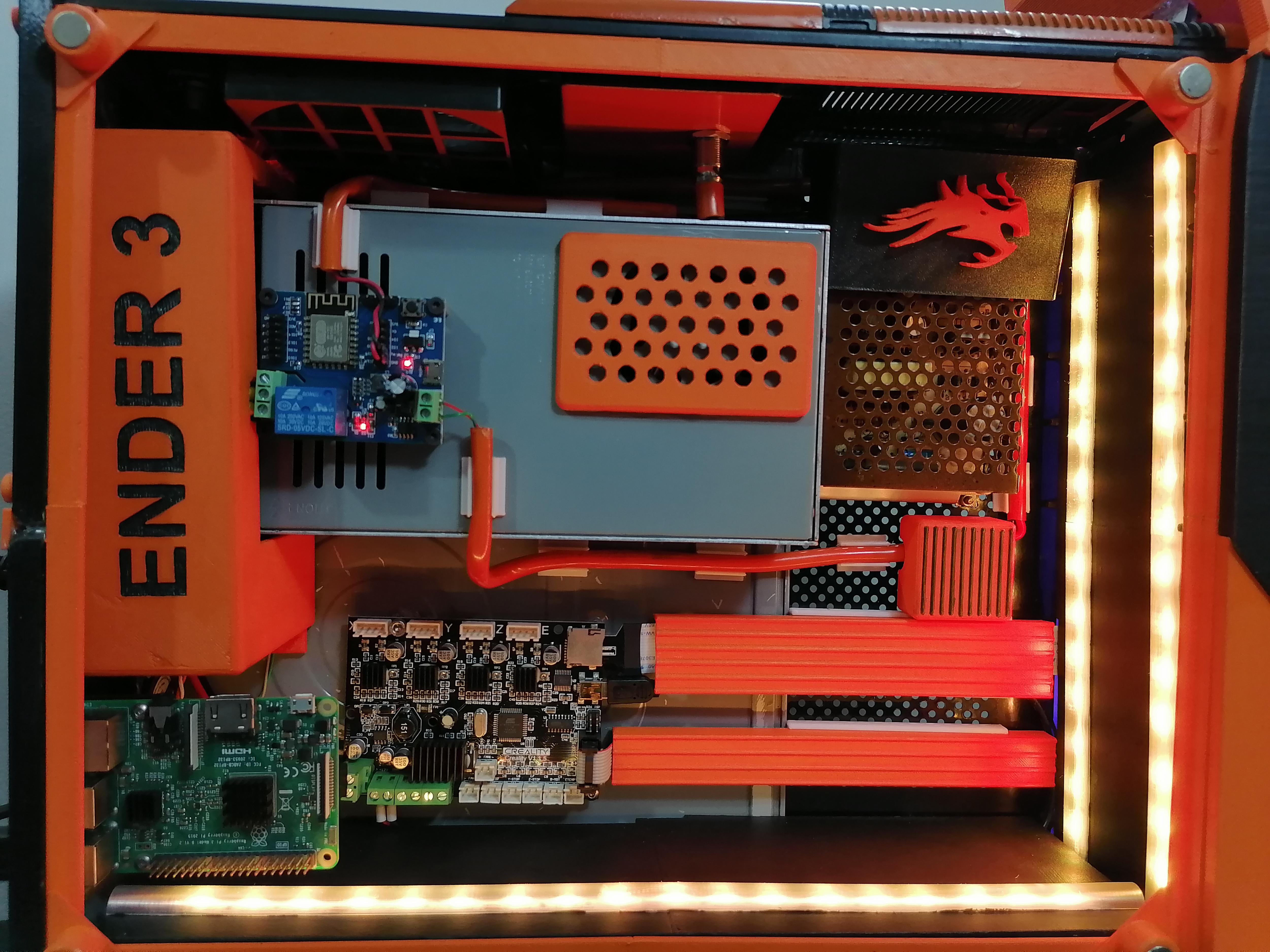
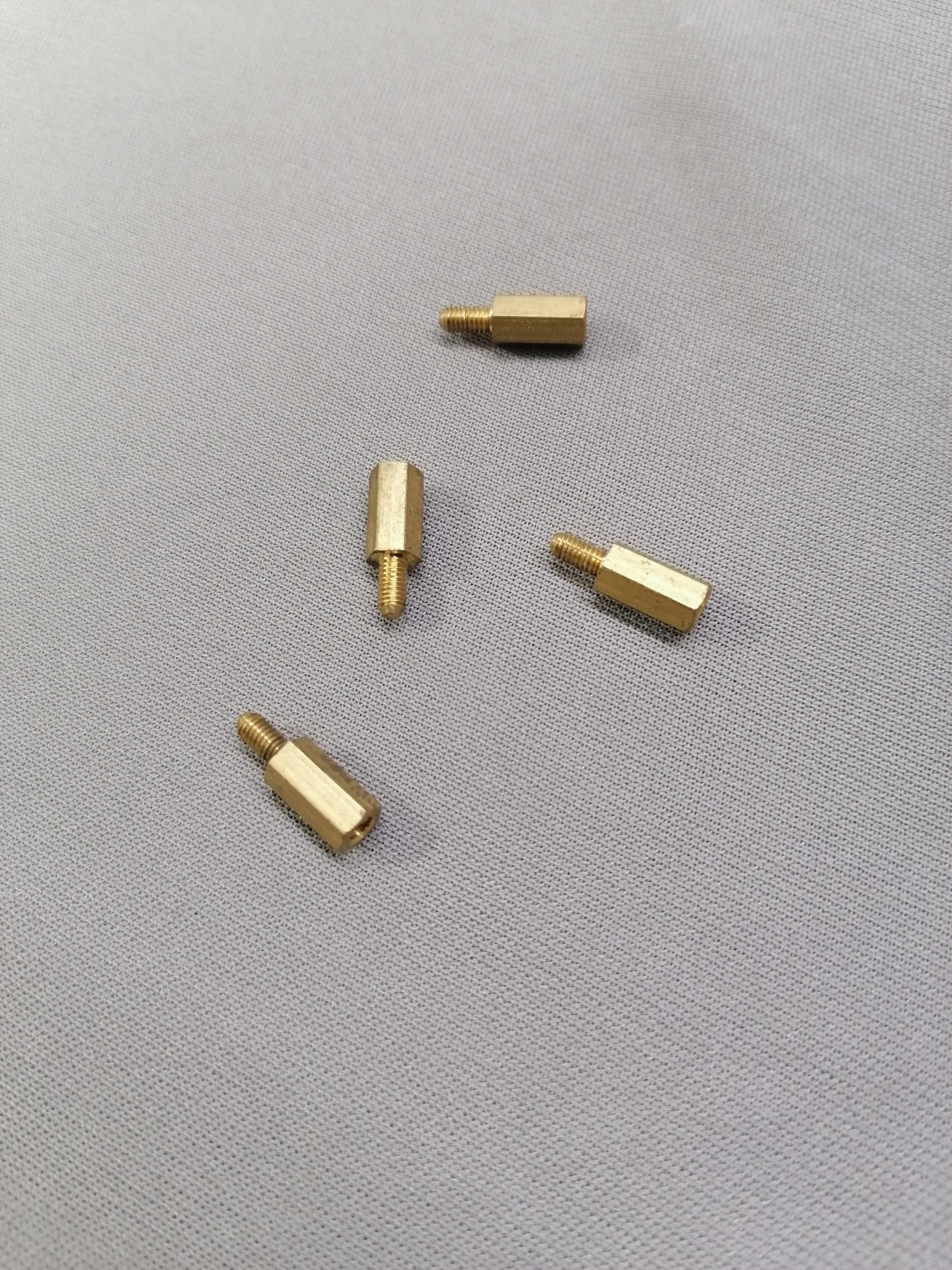
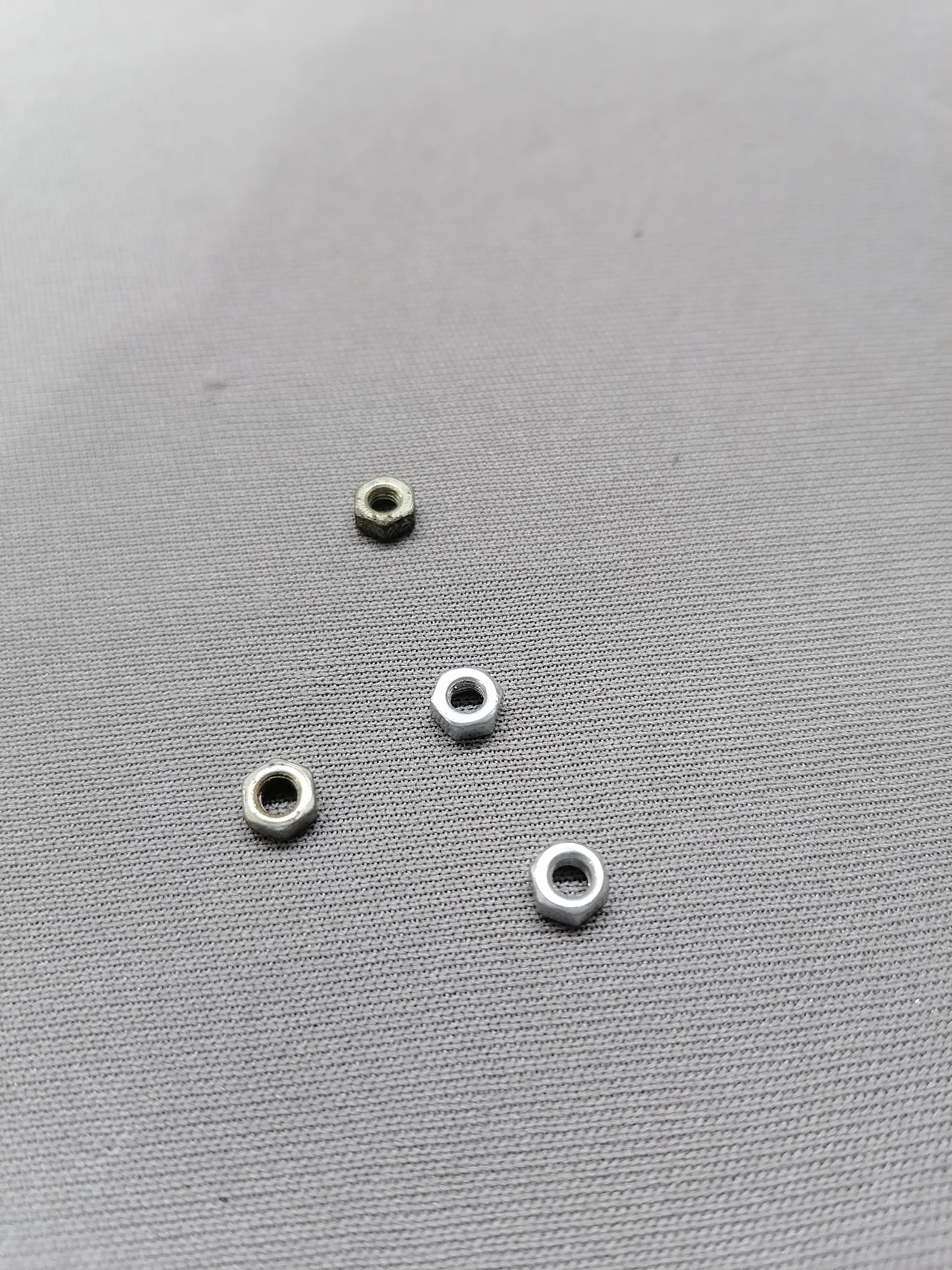
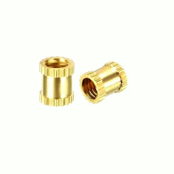
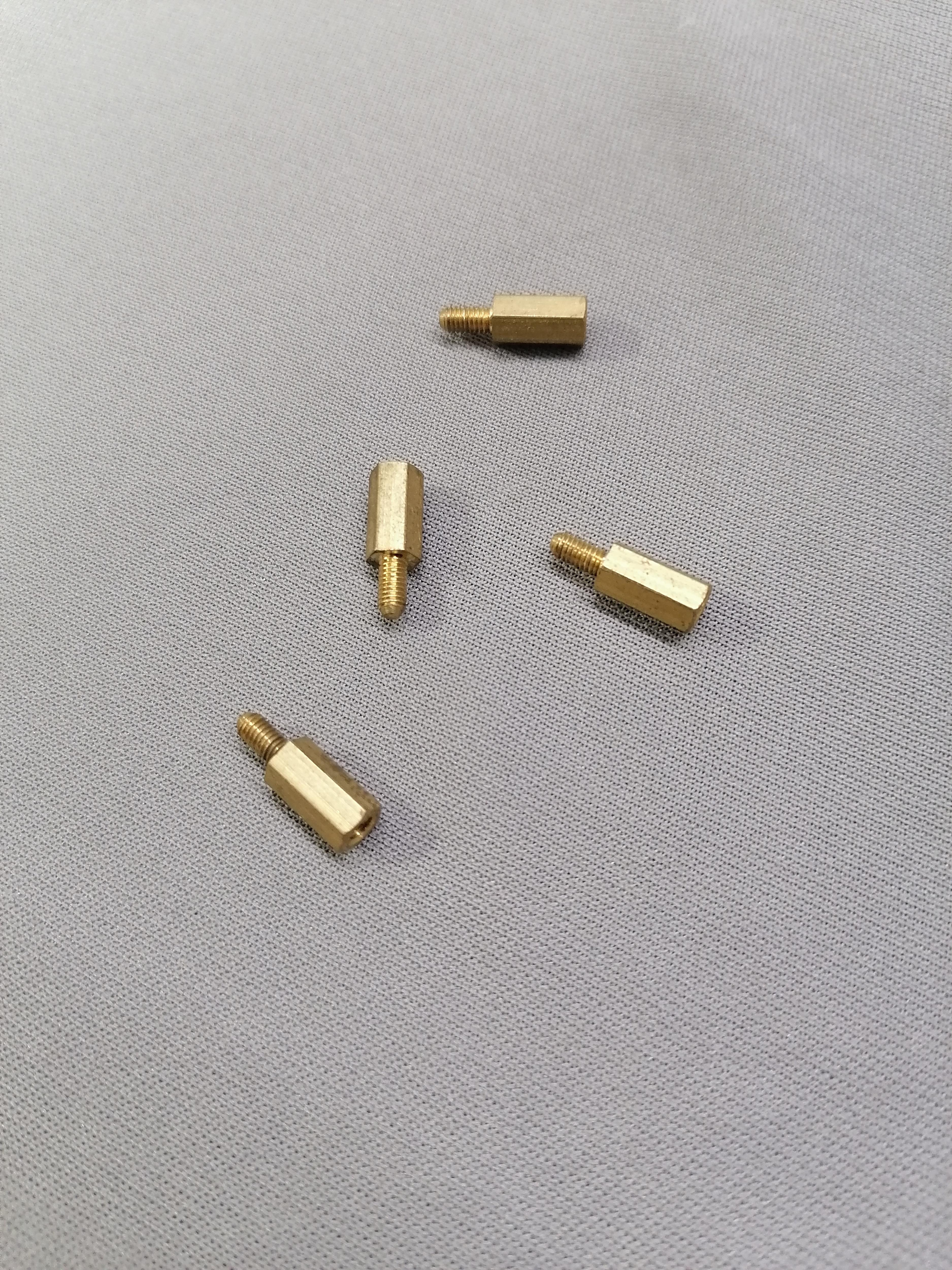
Marks all holes of Power Supply and Mainboard on the inside of CPU case. Here I am using the Brass Female nut to attach the mainboard and throw hole screw nut bolt the power supply attaching. Also noted that here I am using another power supply for other components.
Note: Refer image for more understanding.
Tip: Use solder wire and solder Iron to joint Brass Nut on metal plate of CPU.
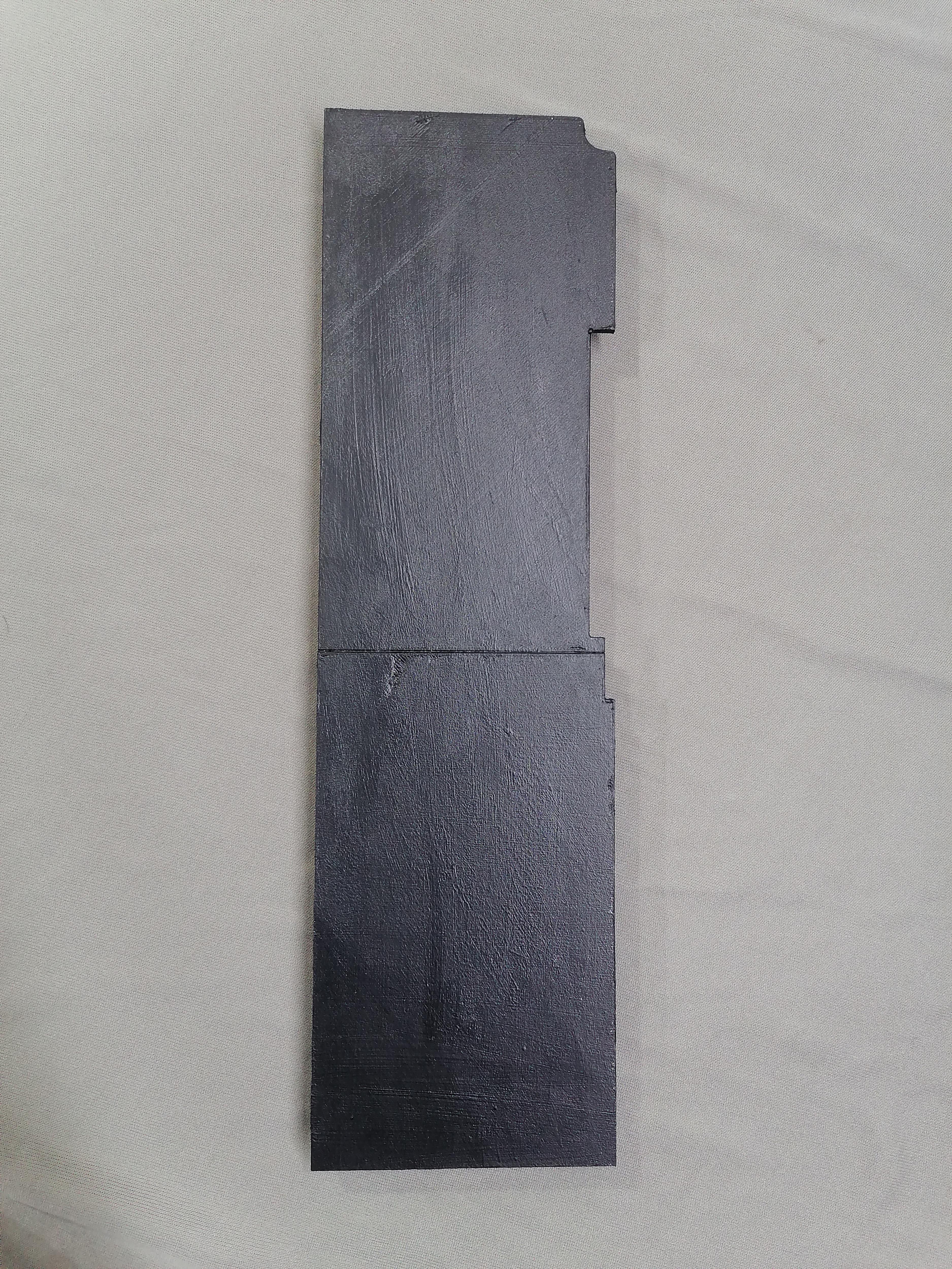
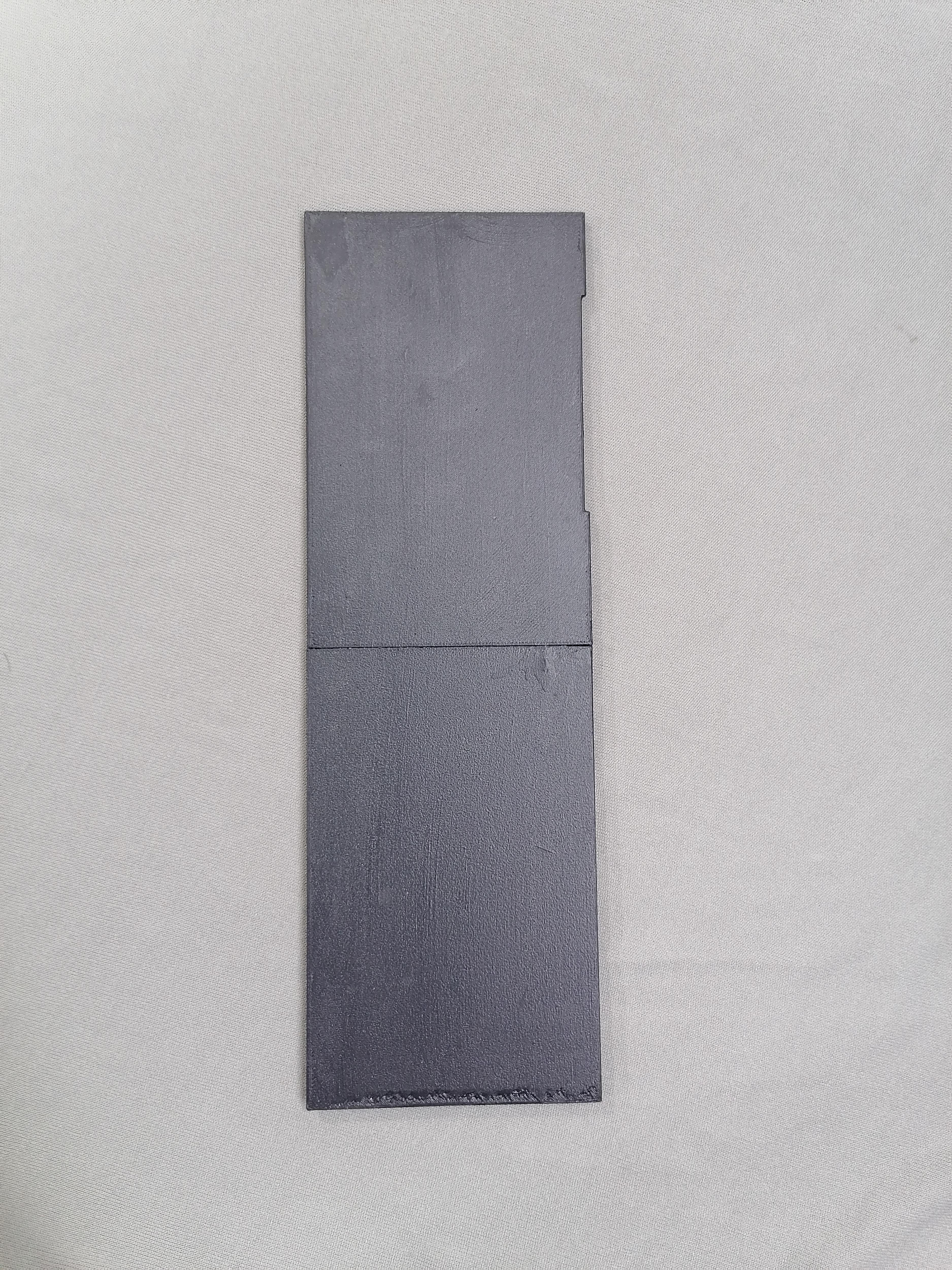
Painting All Parts
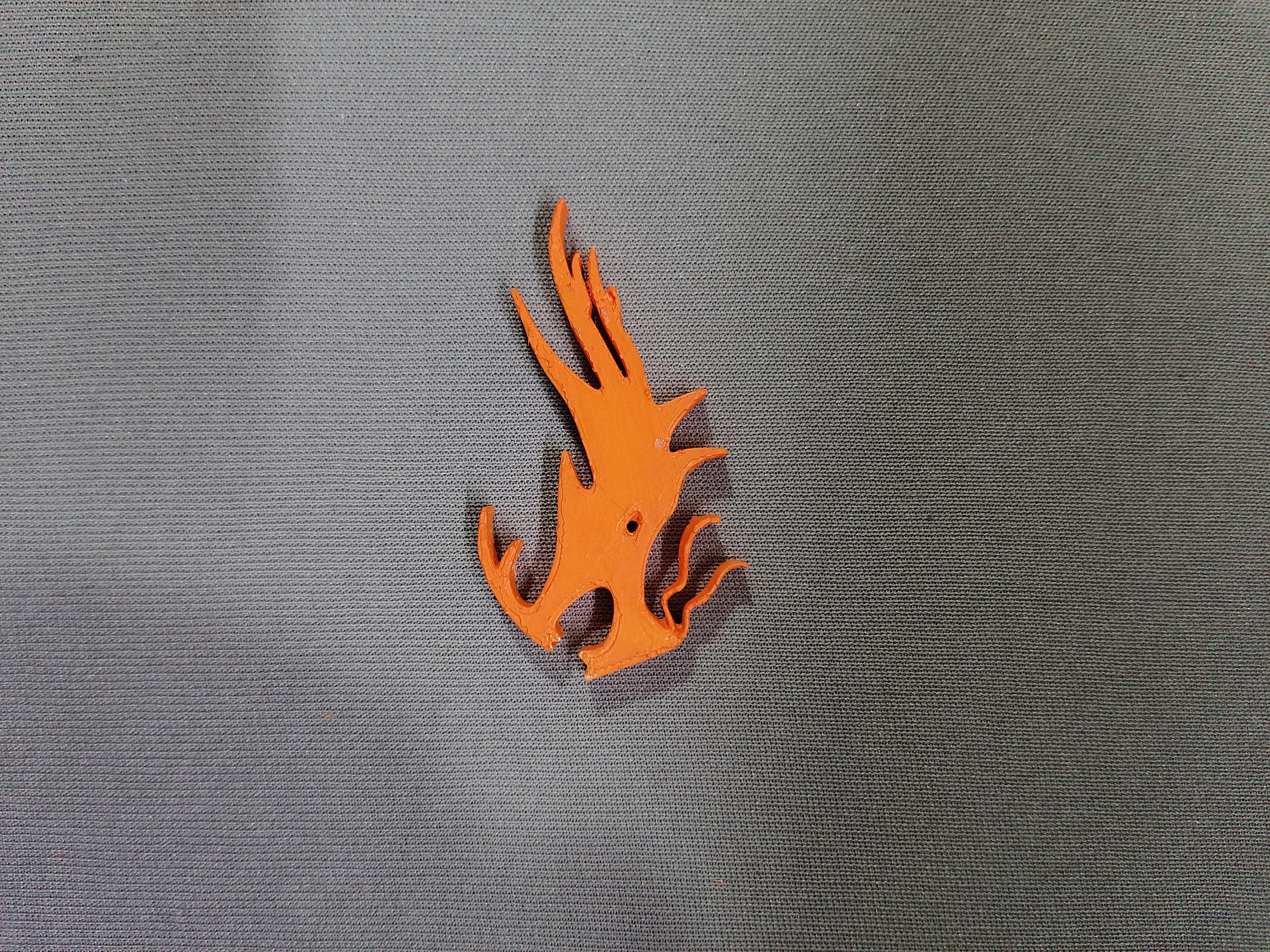
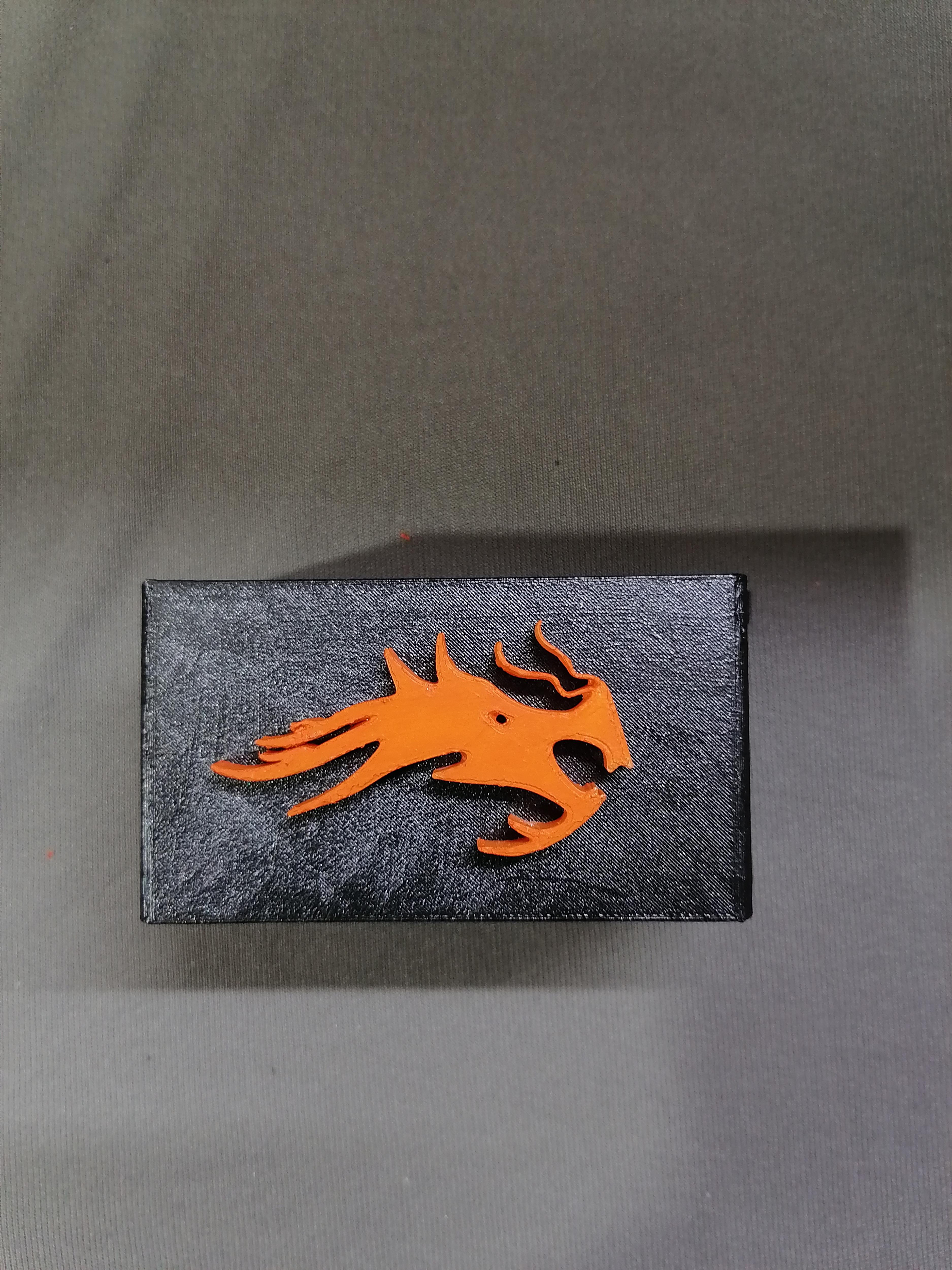
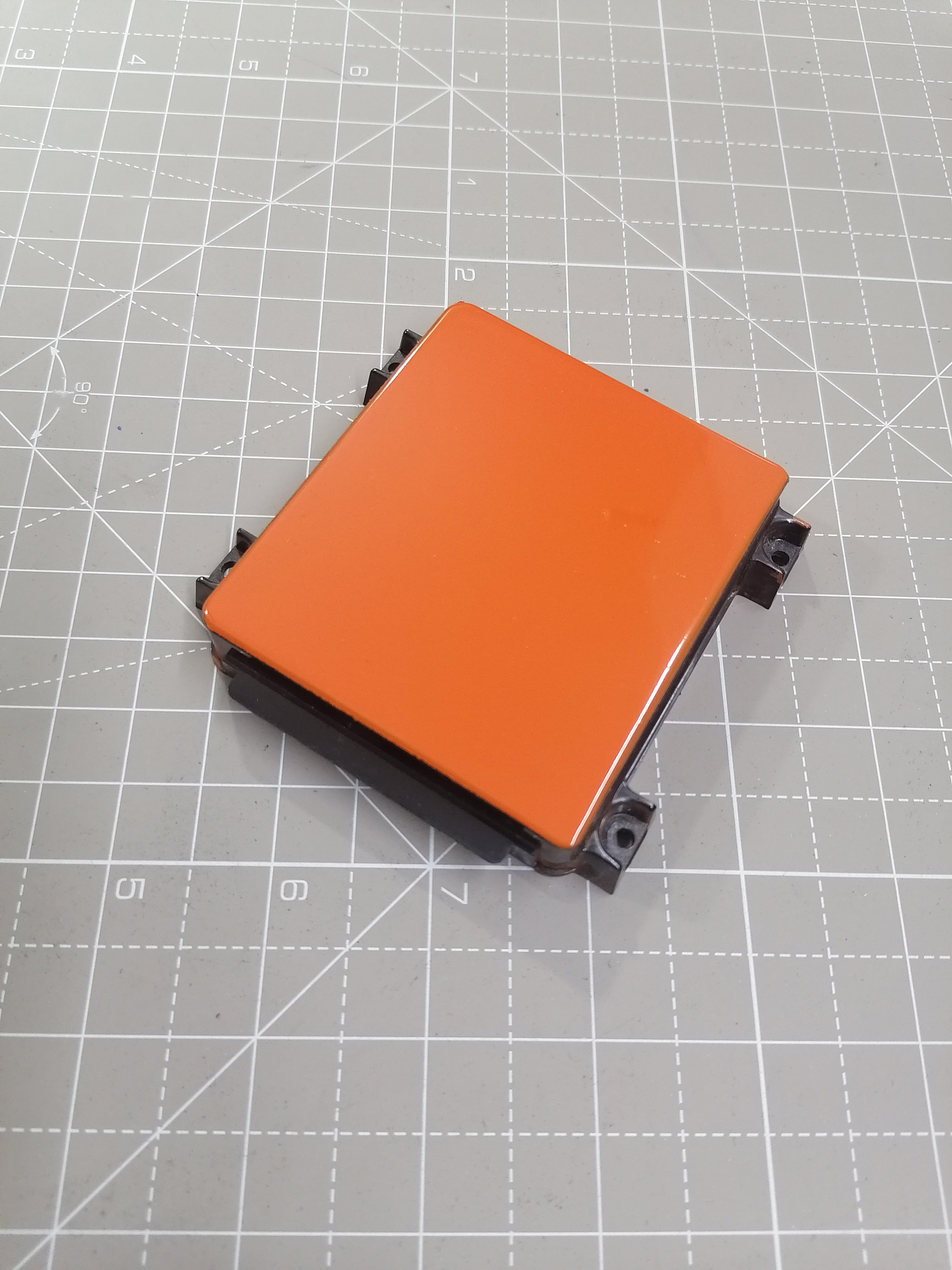
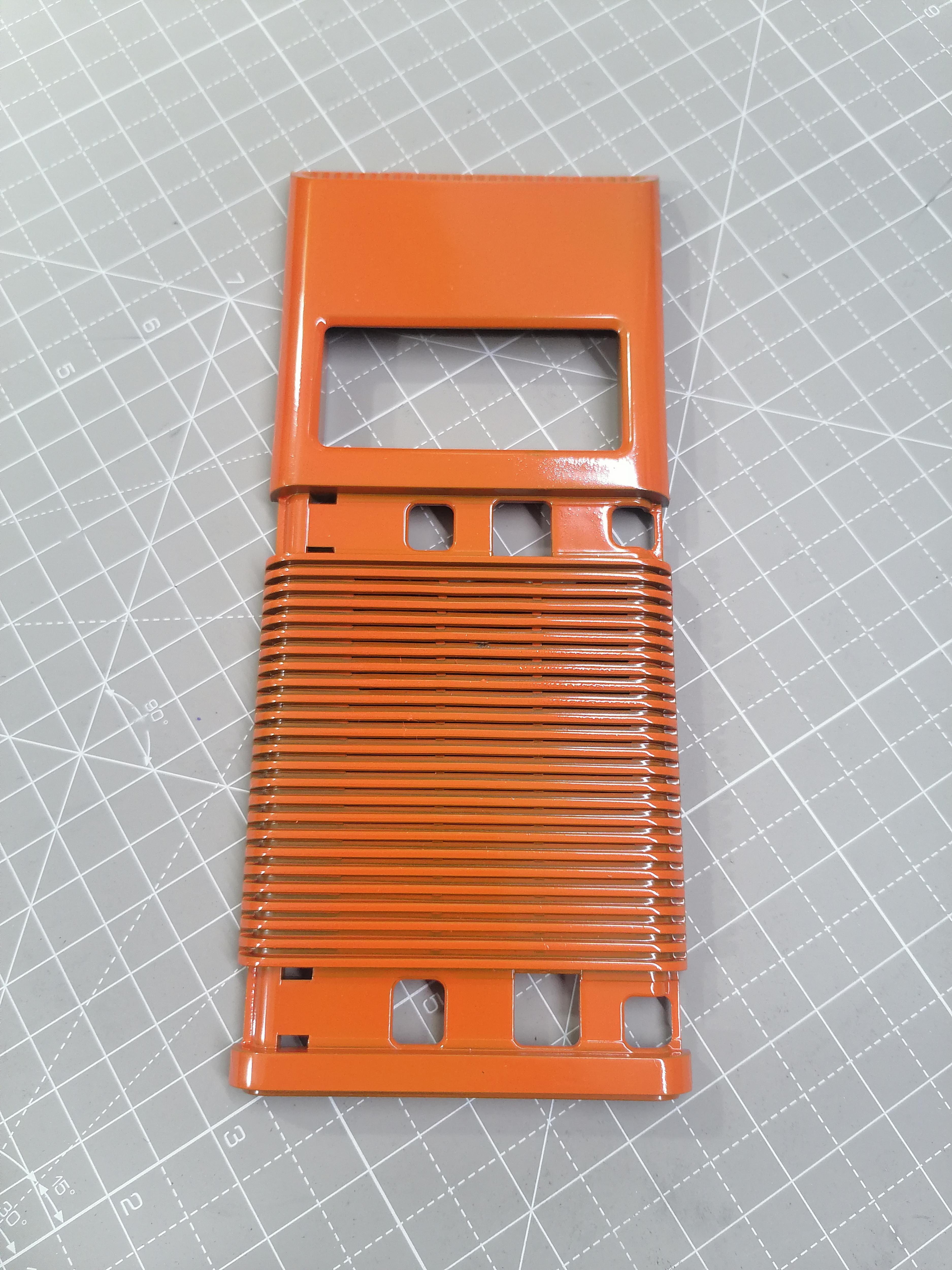
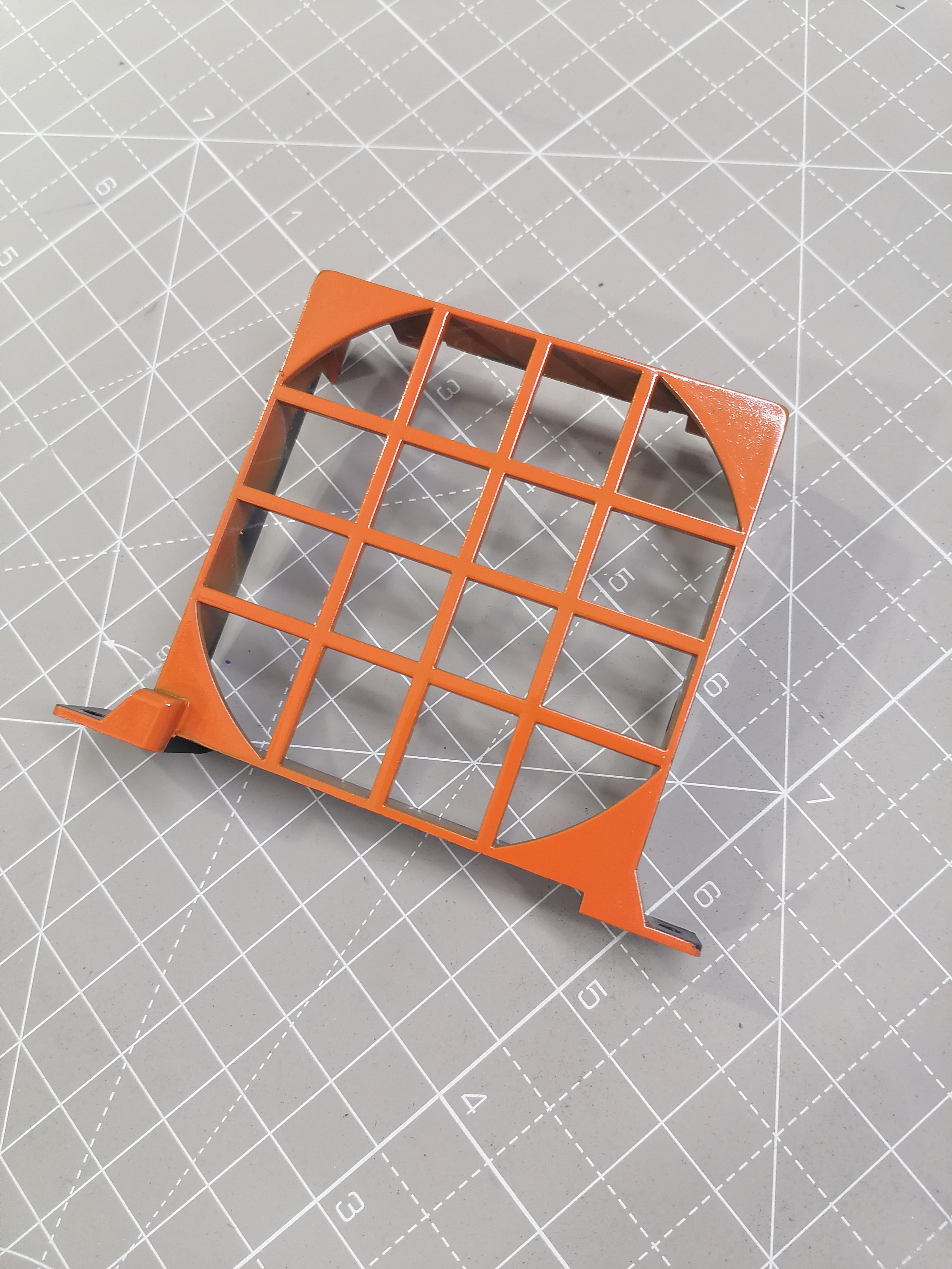
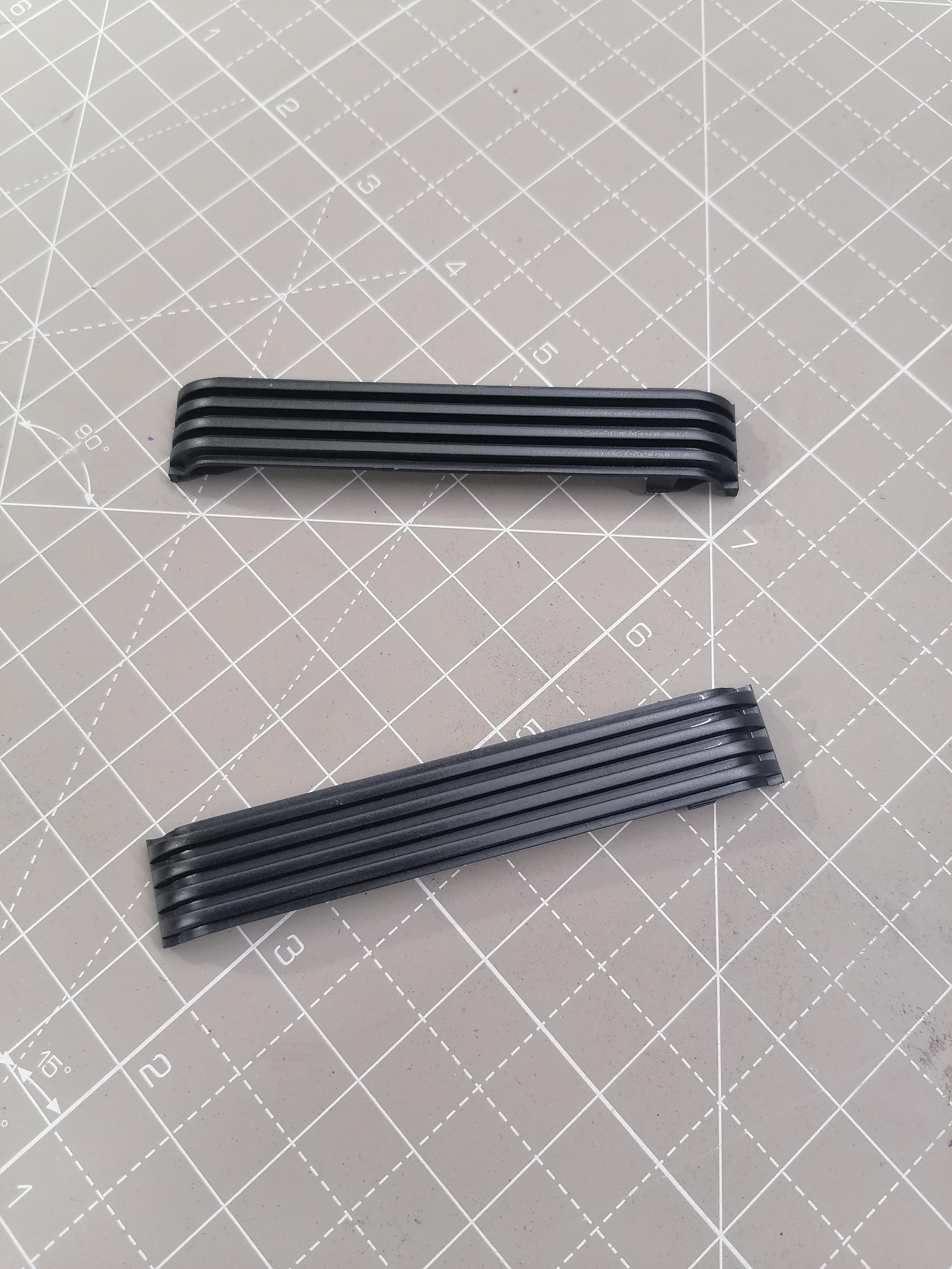
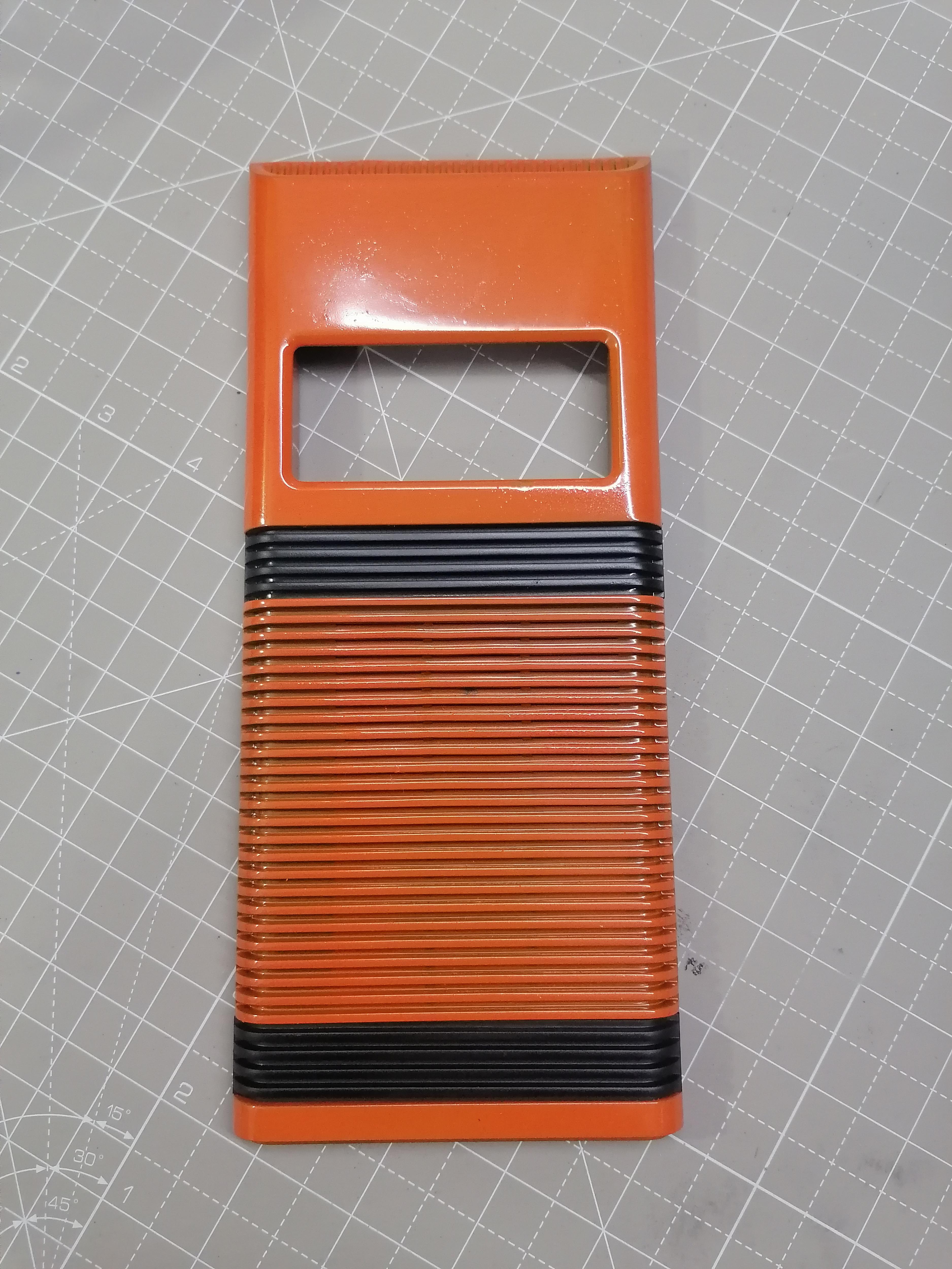
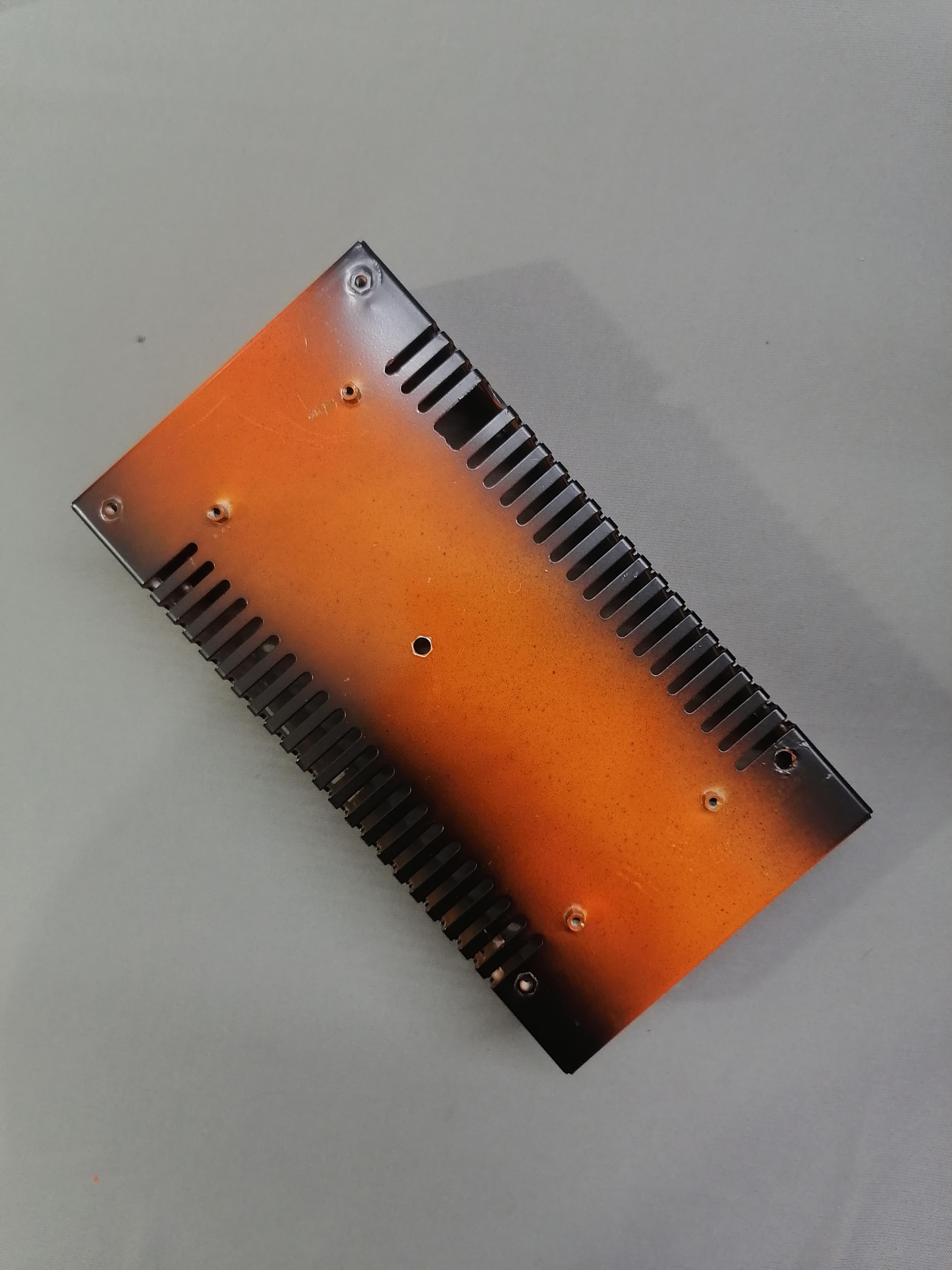
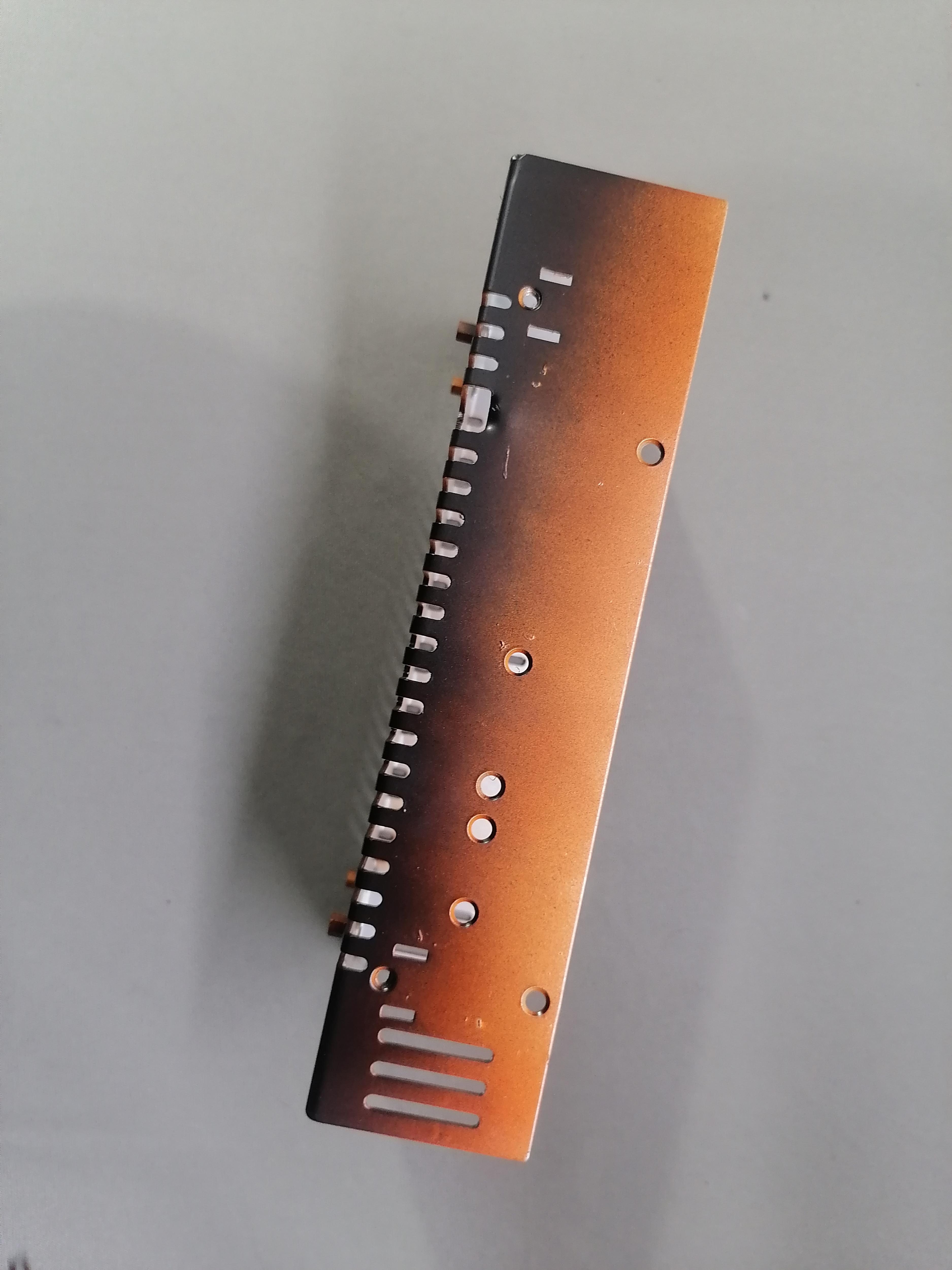
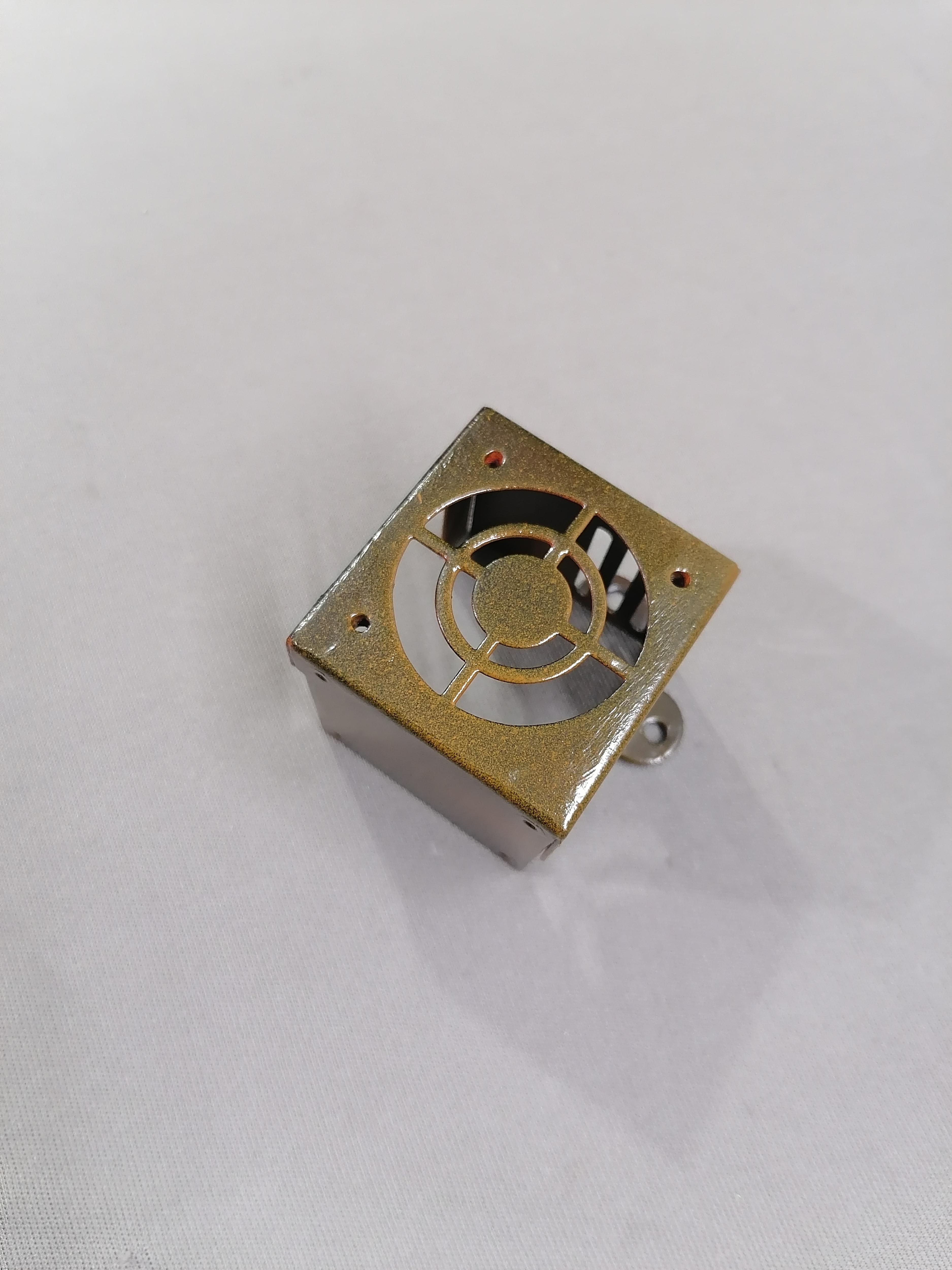
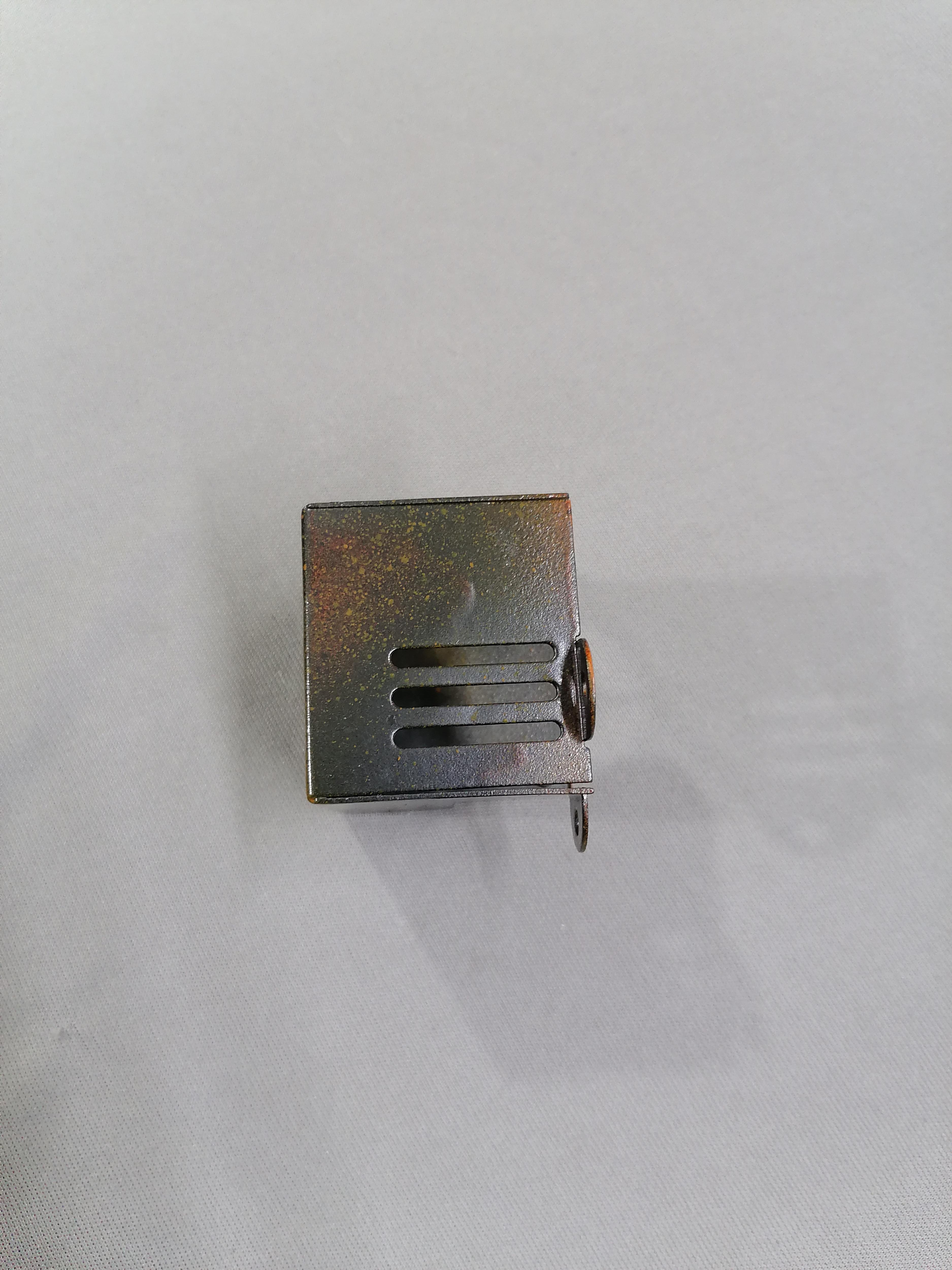

Do paint work after all holing part are done and joining of all part done.
Here I choose the Black, Orange and Grey colours.
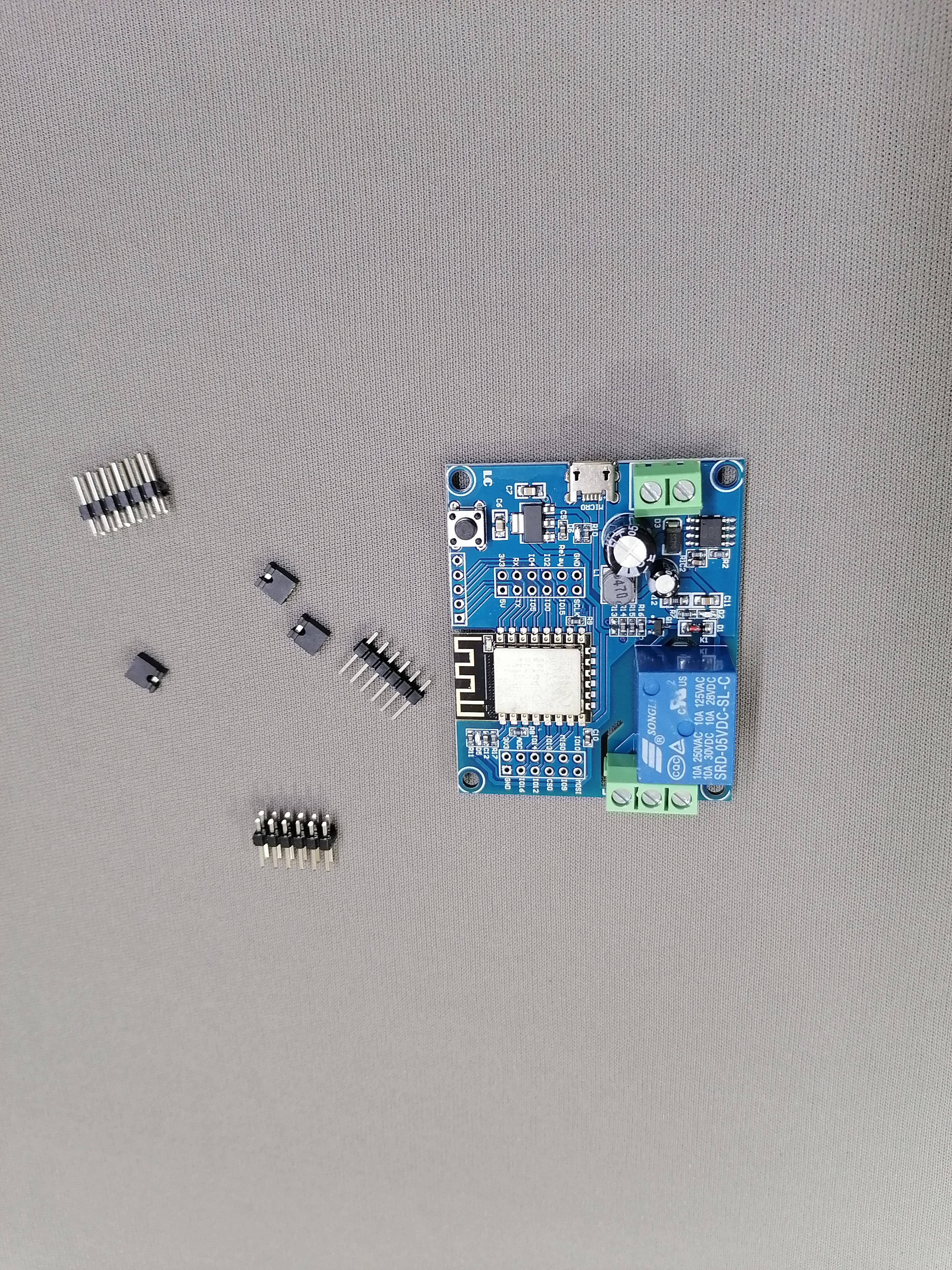
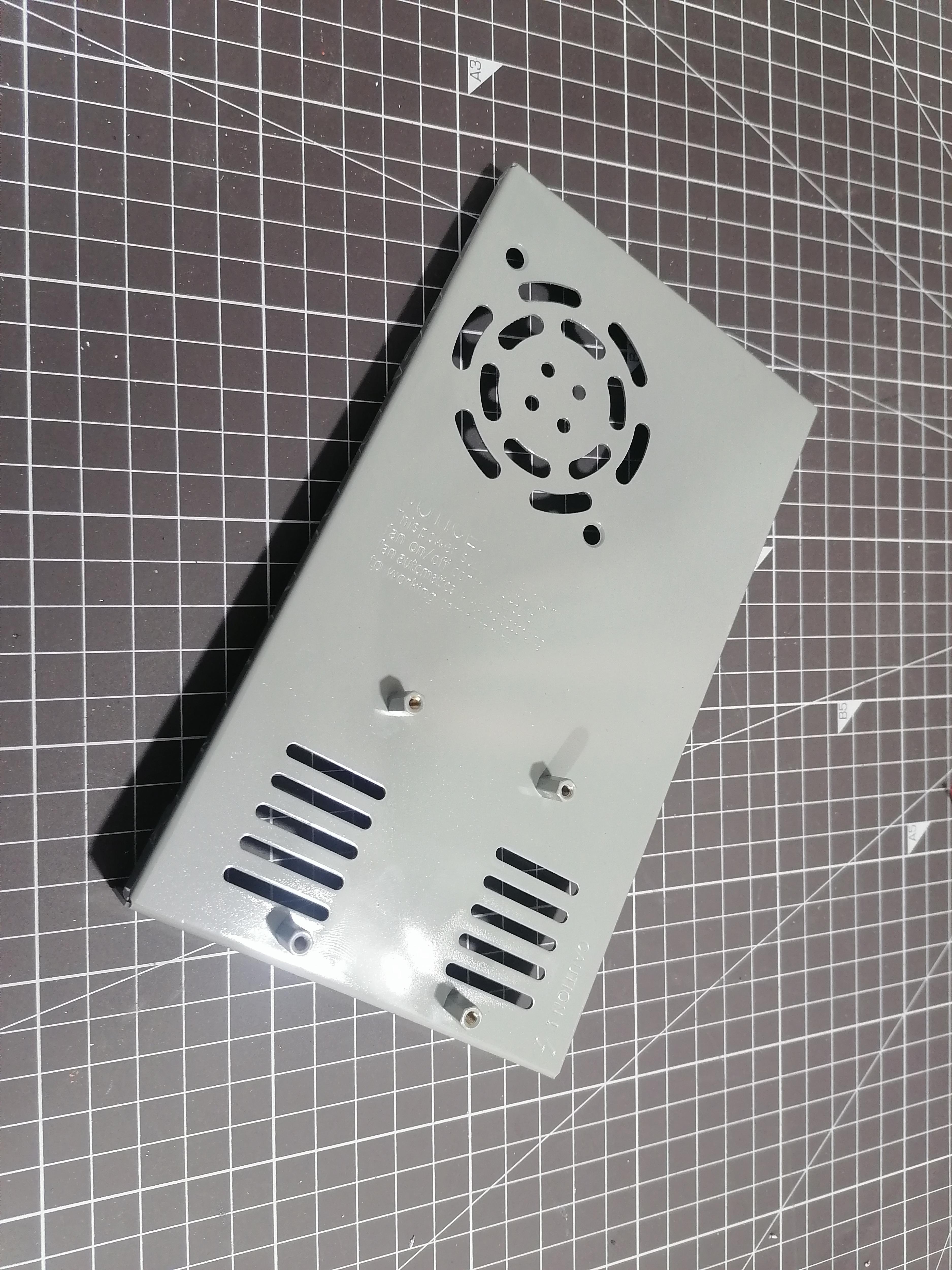
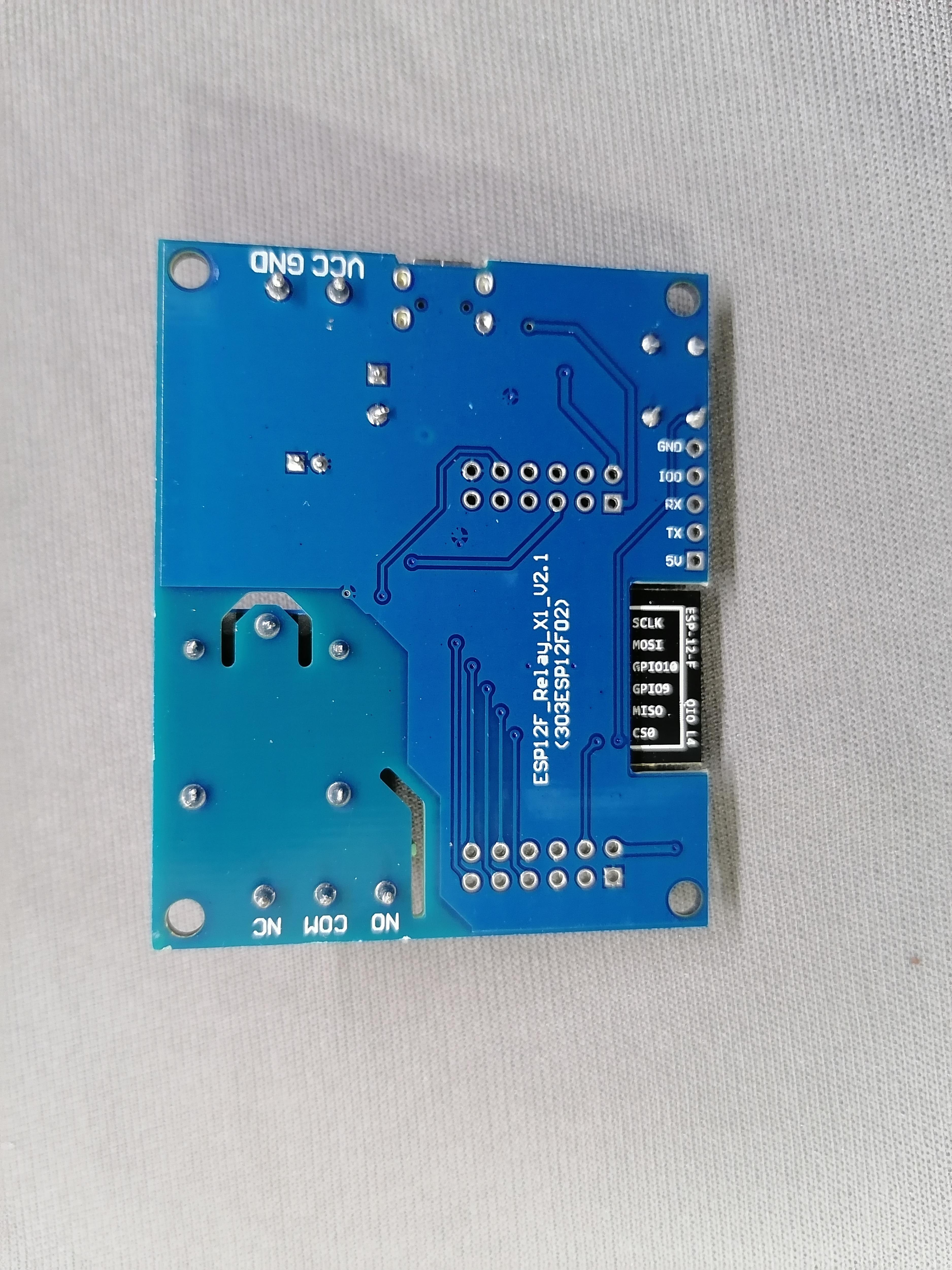
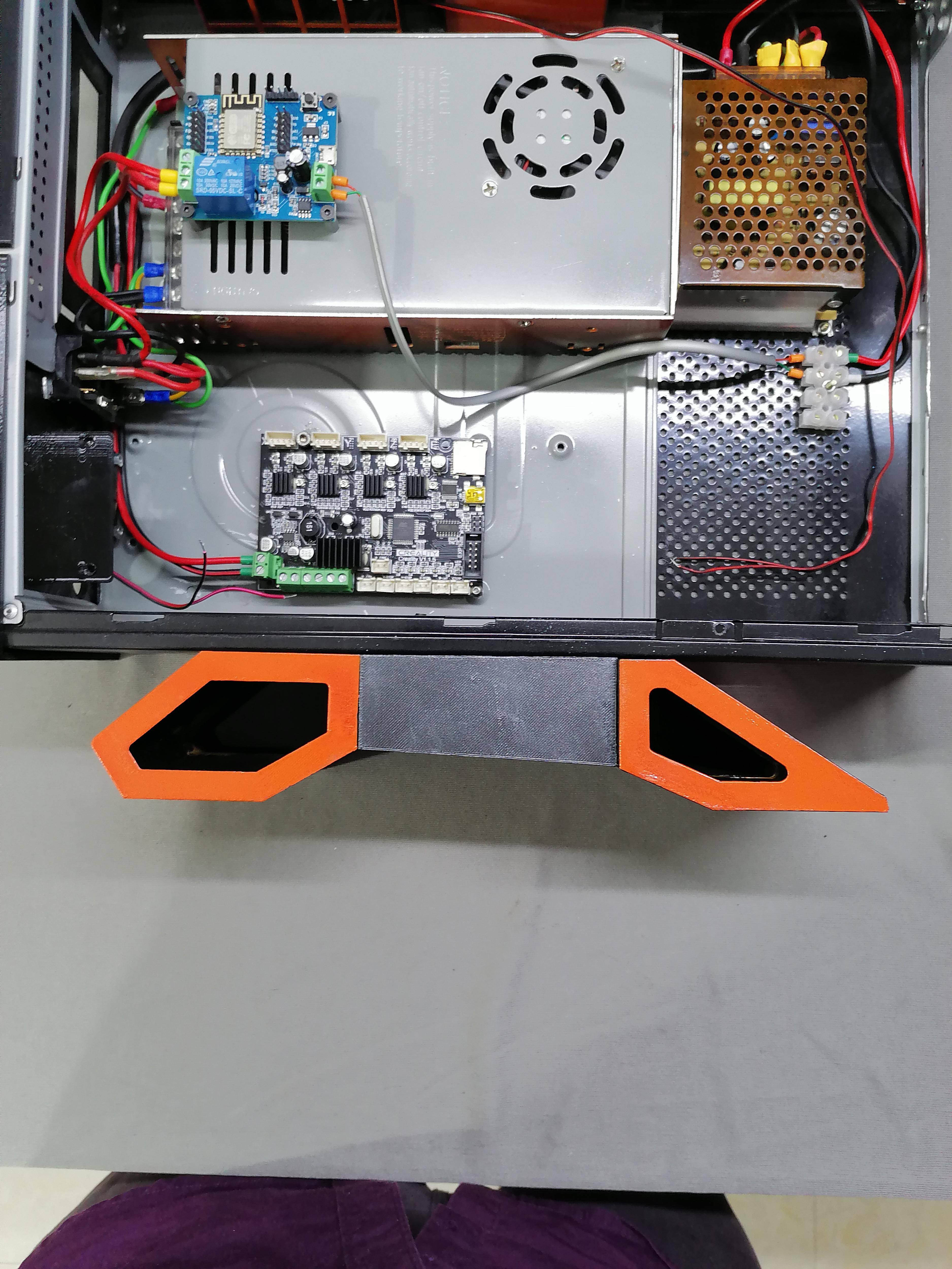
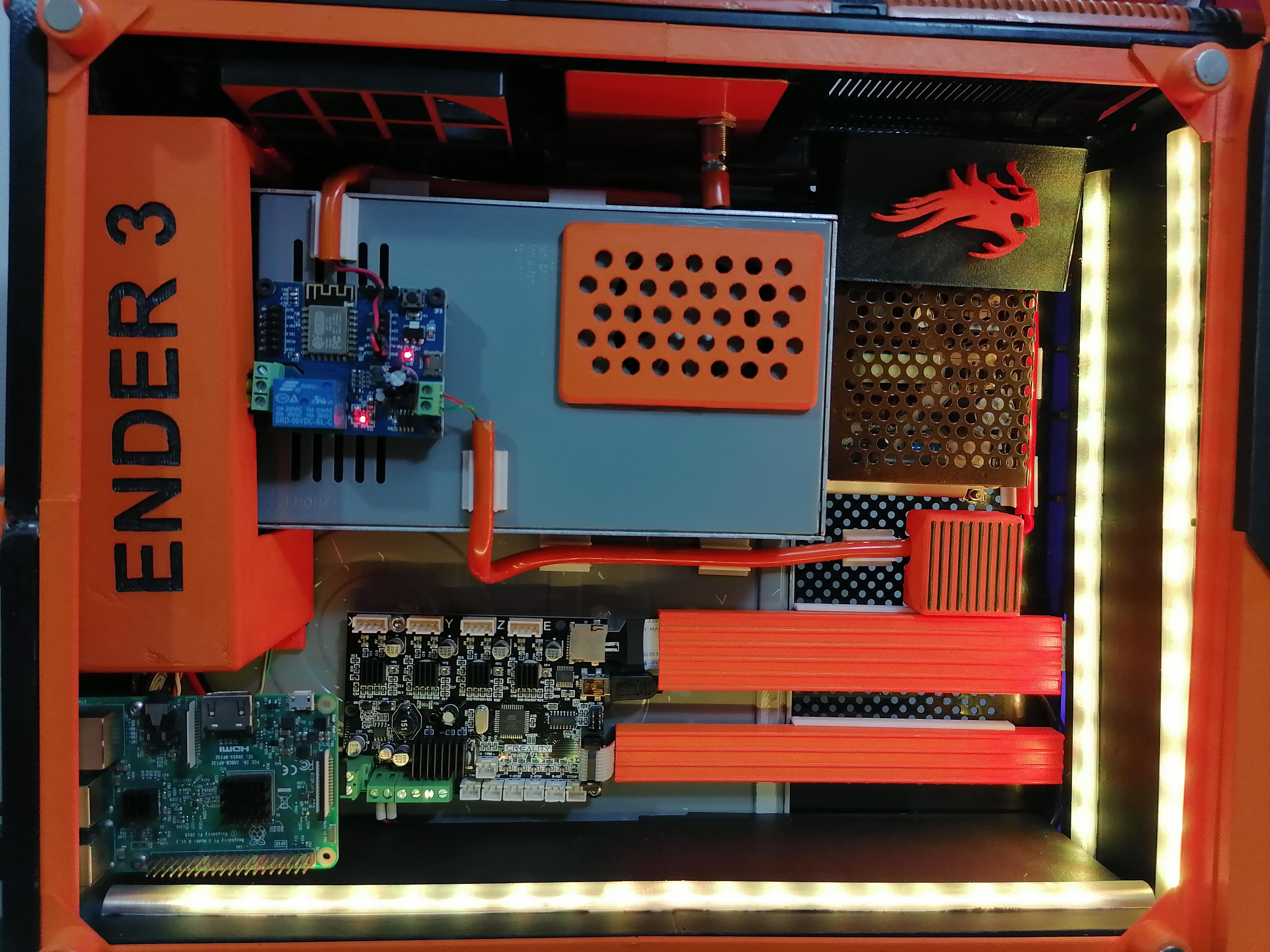
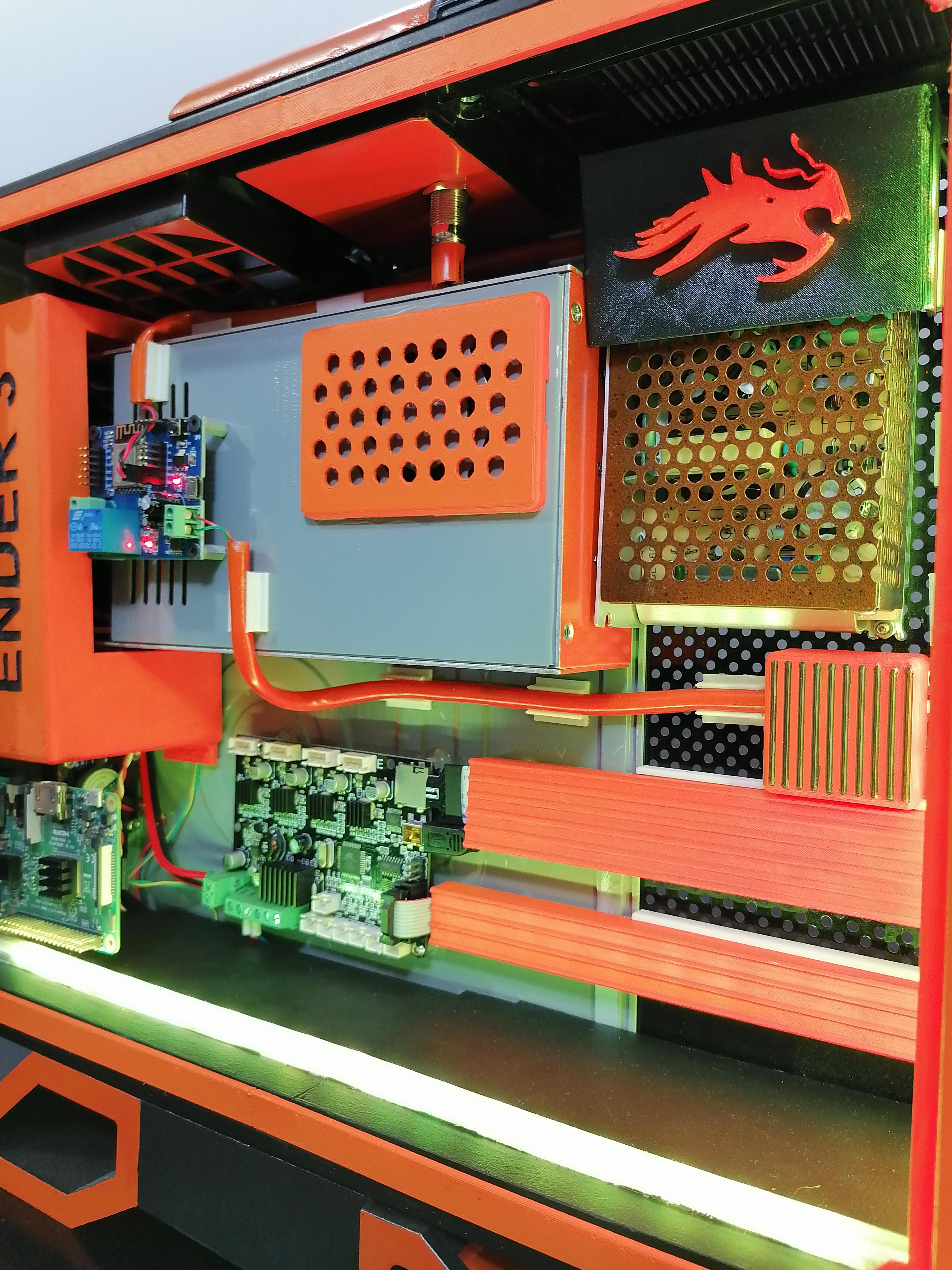
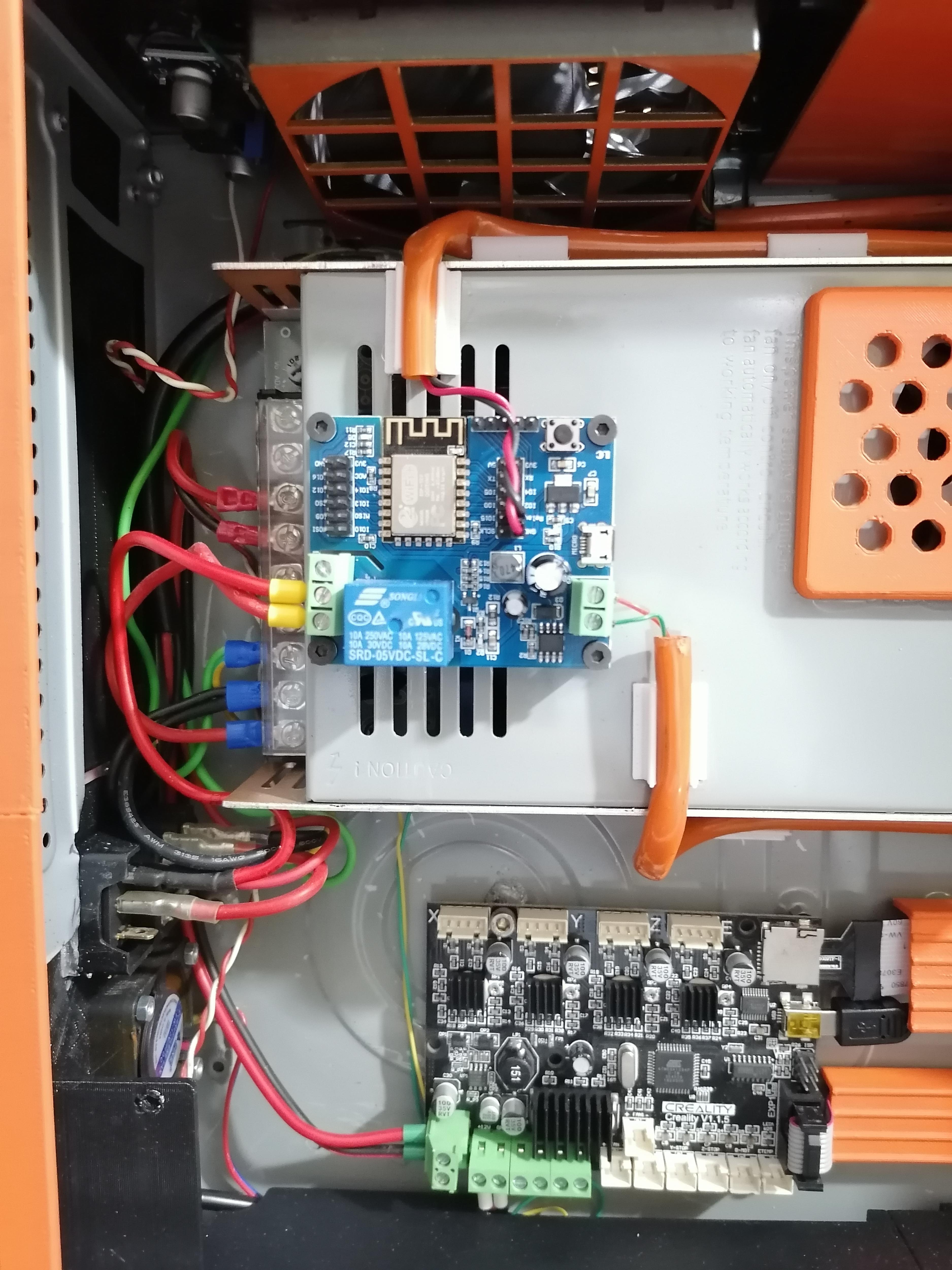
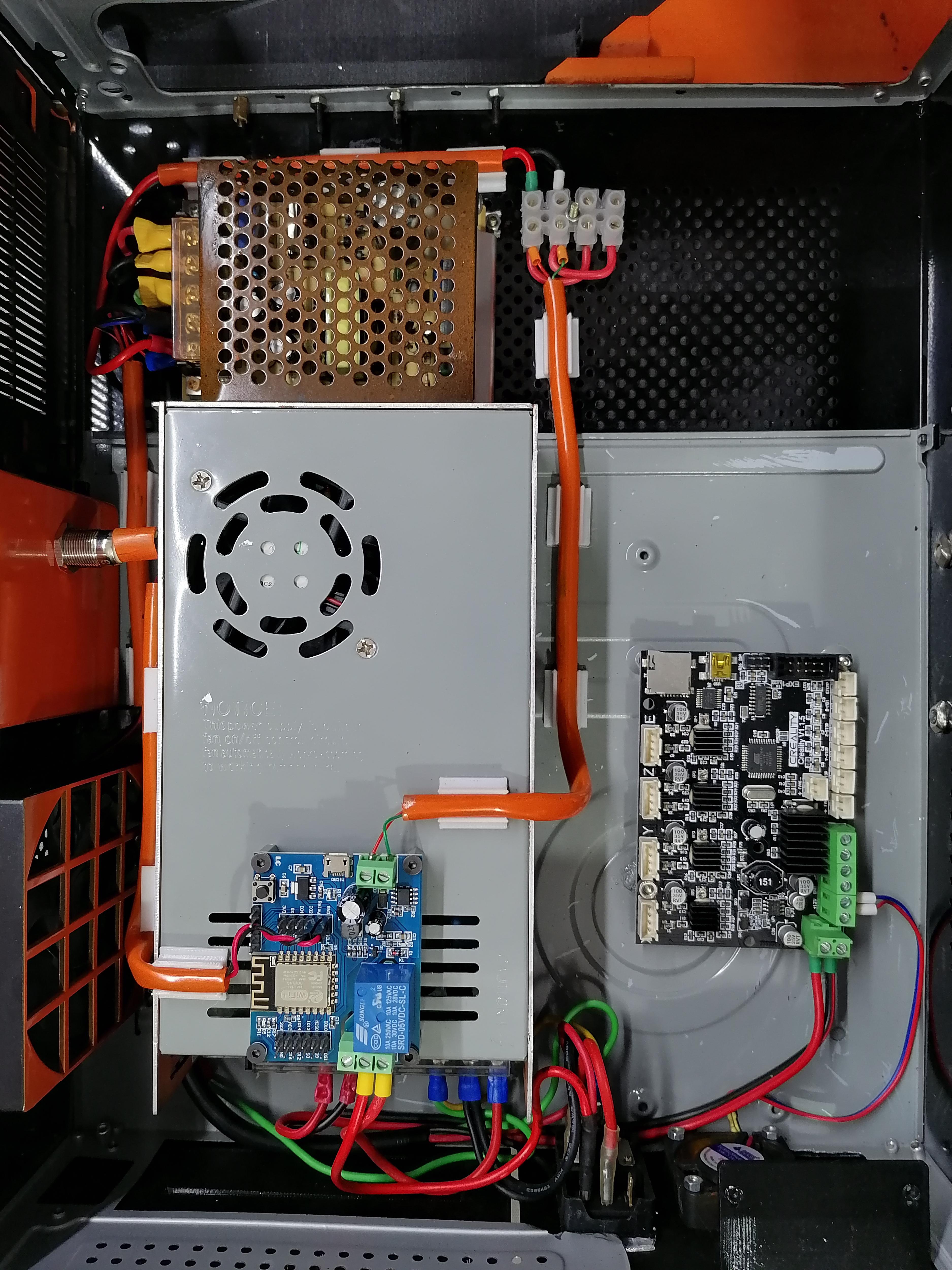
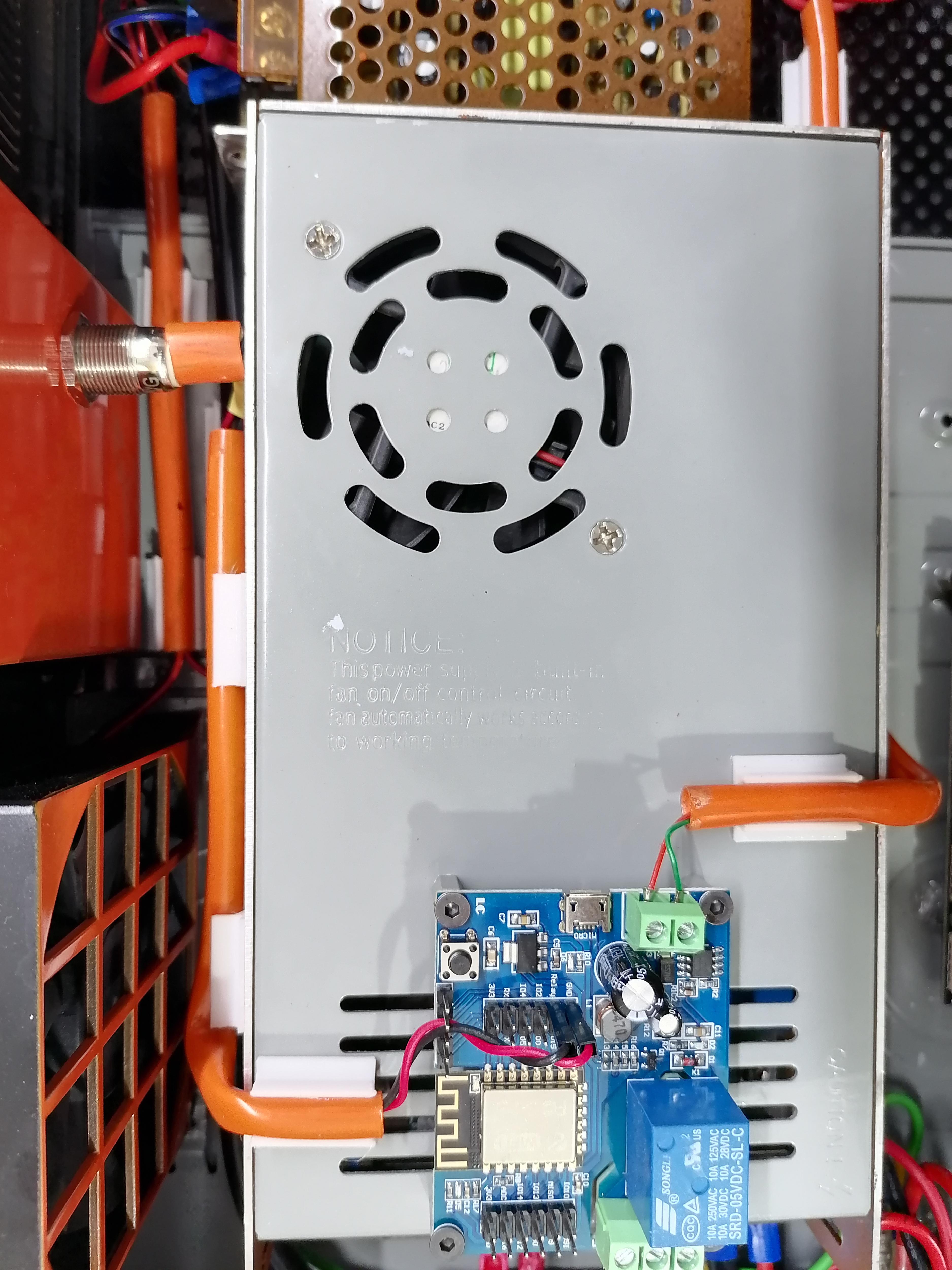
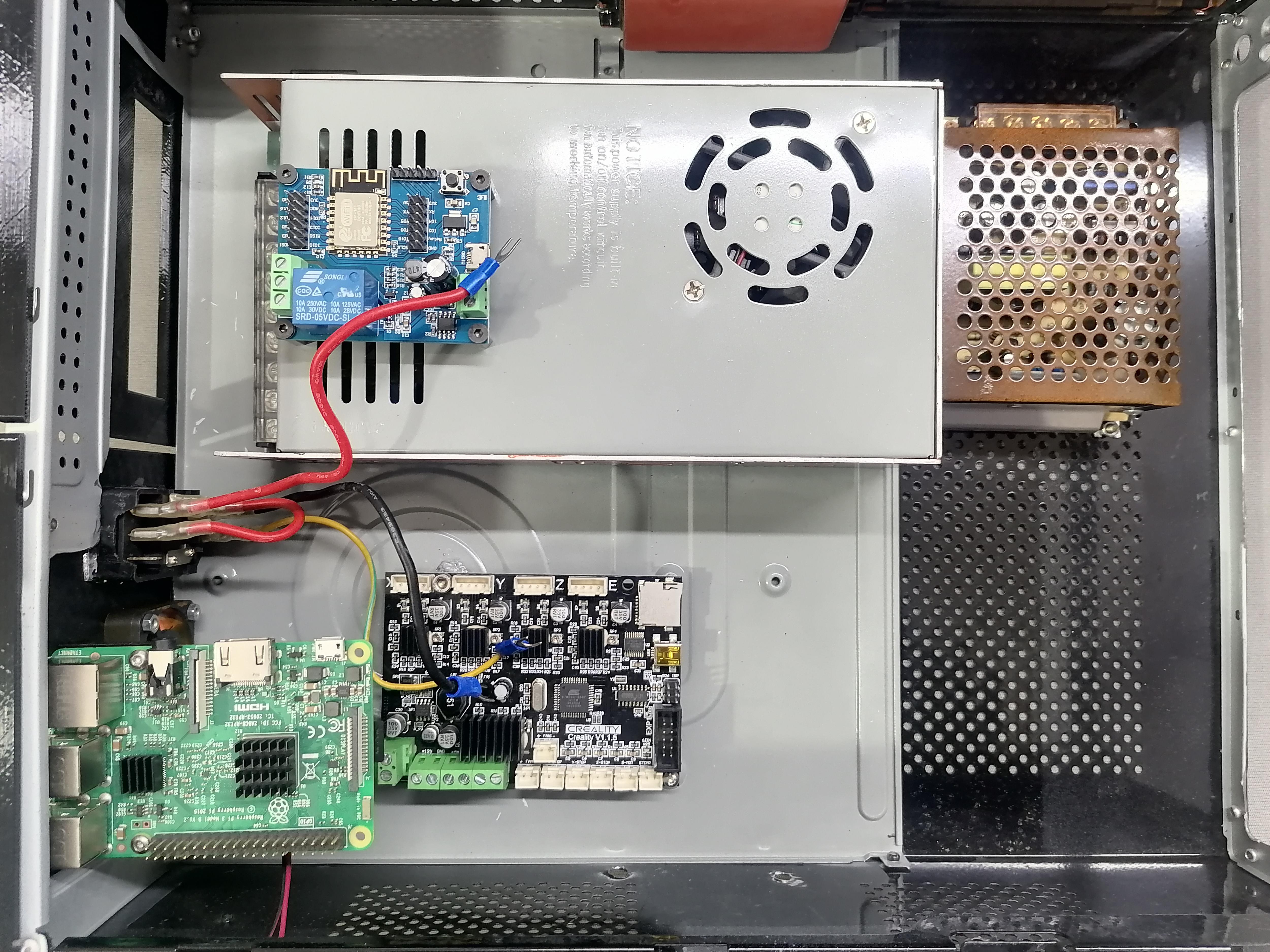
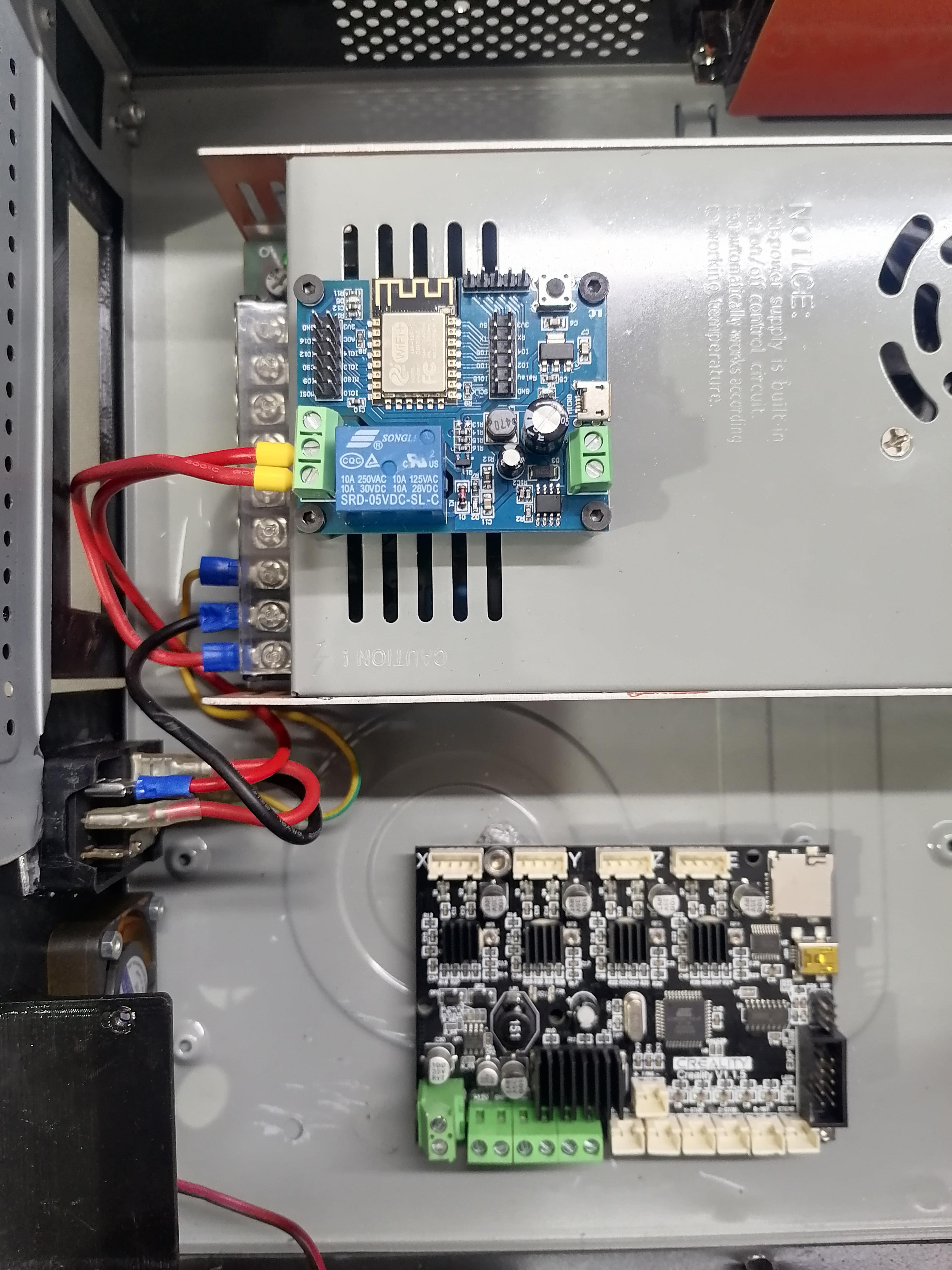
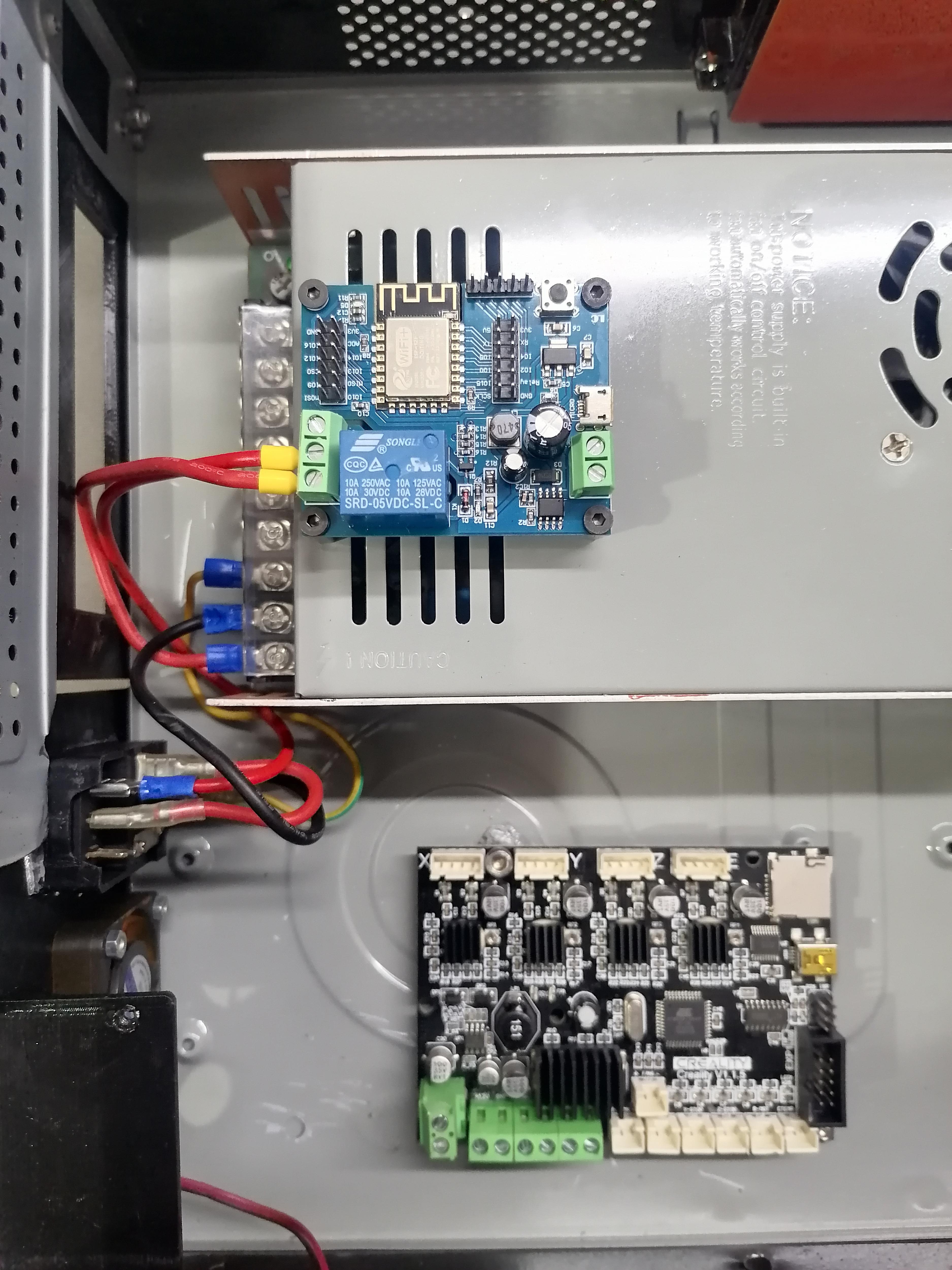
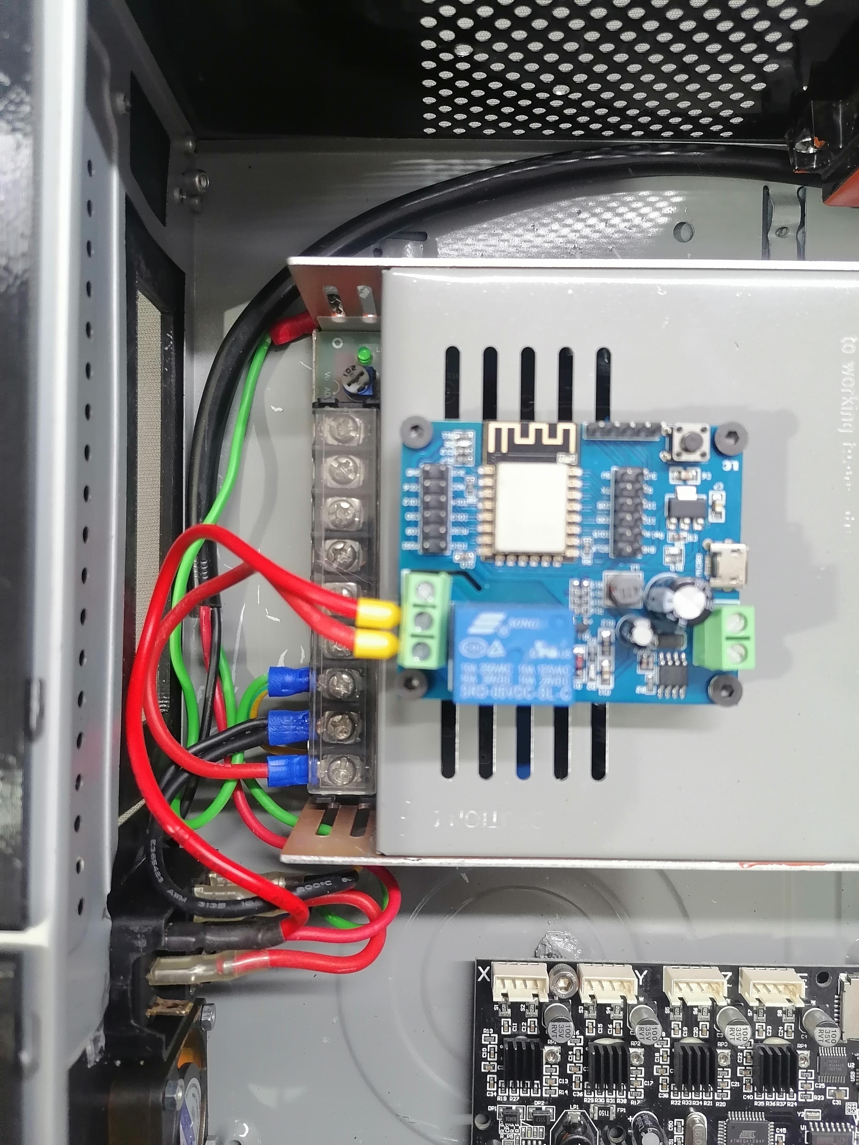
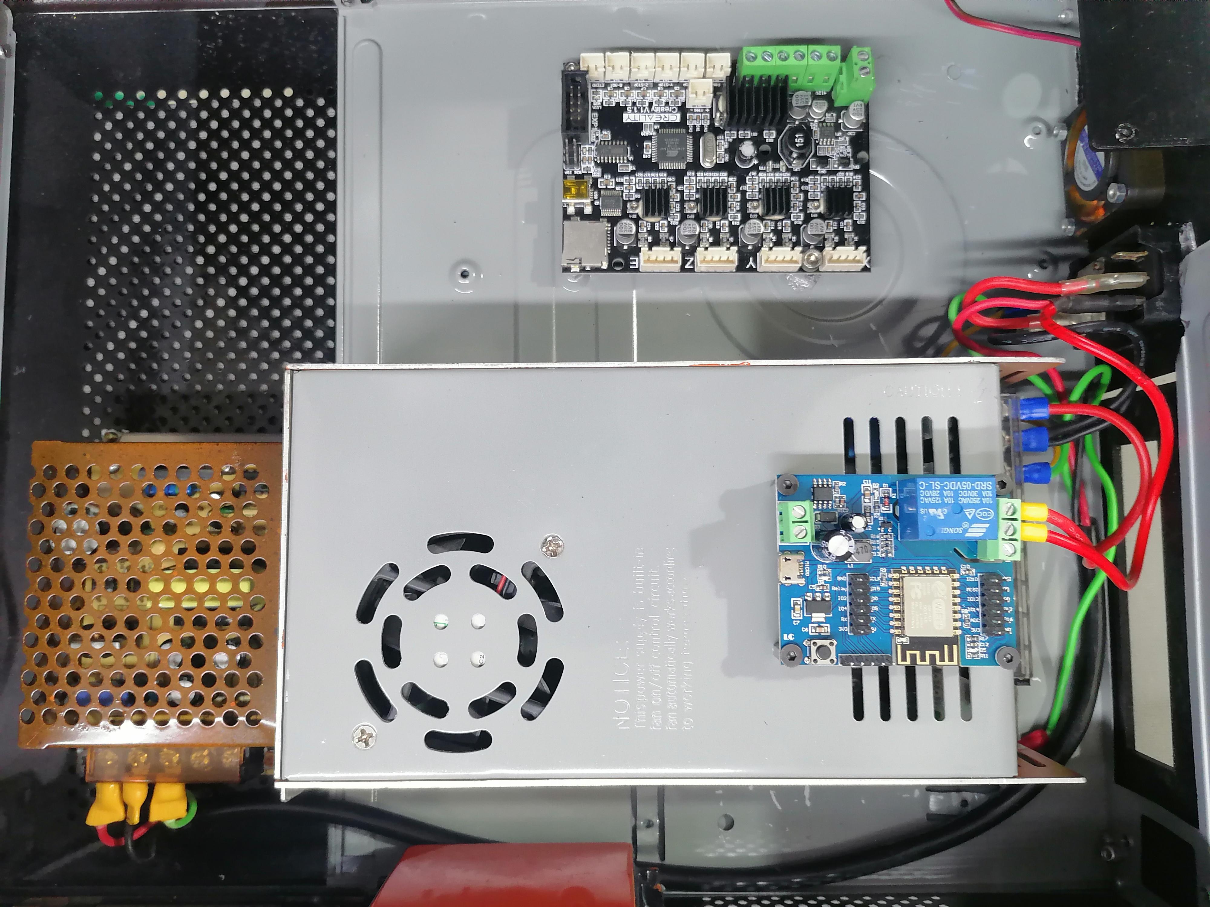
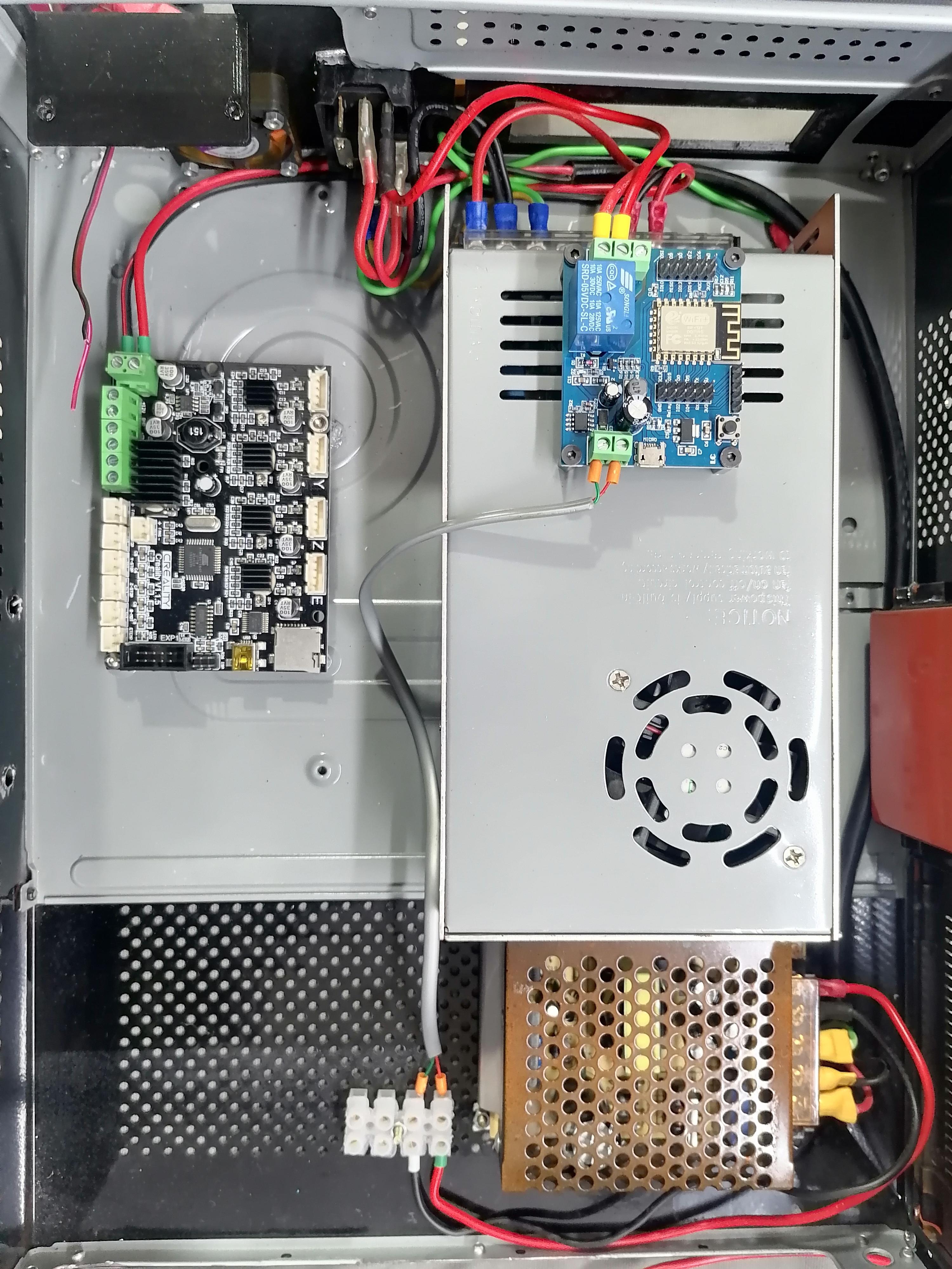
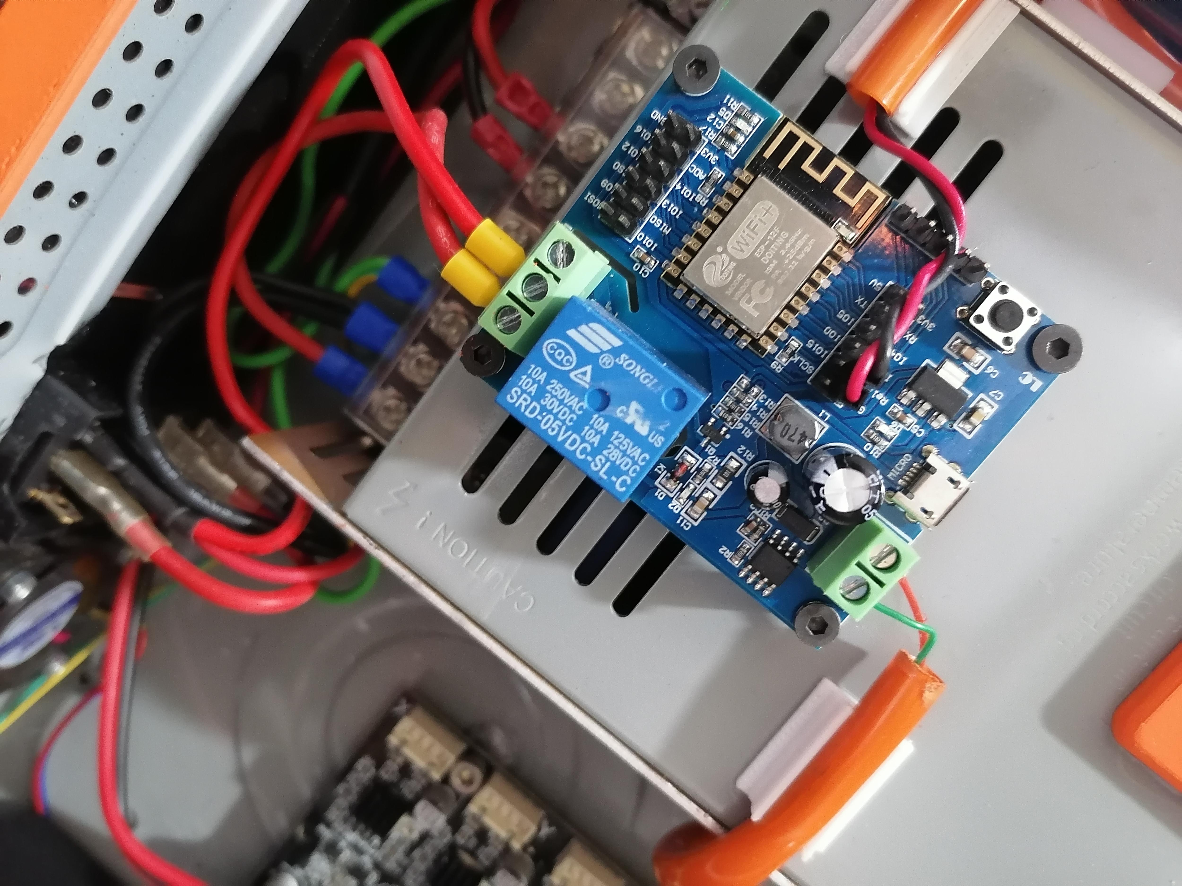
Attaching the WiFi Relay Module on to Power Supply
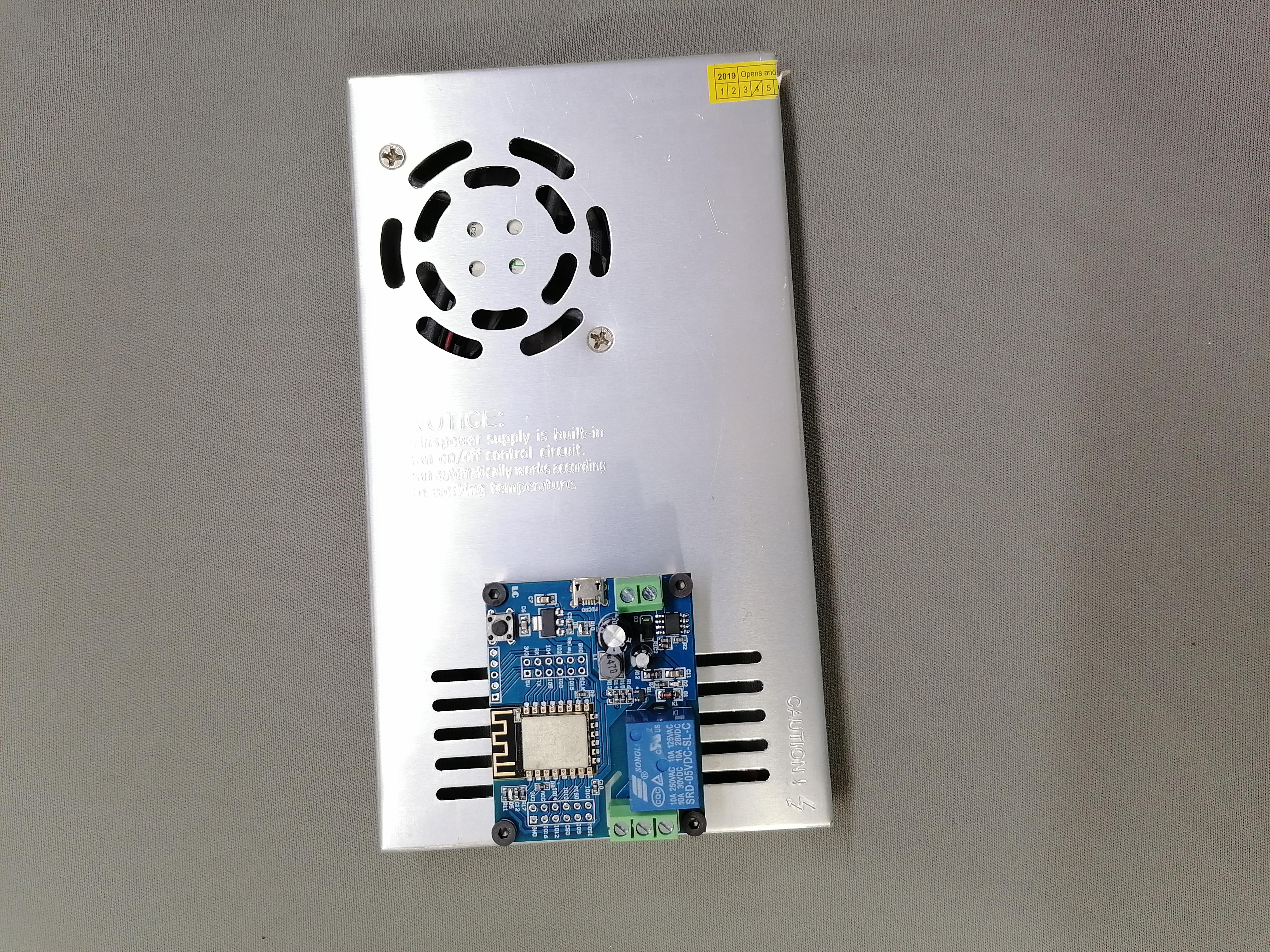
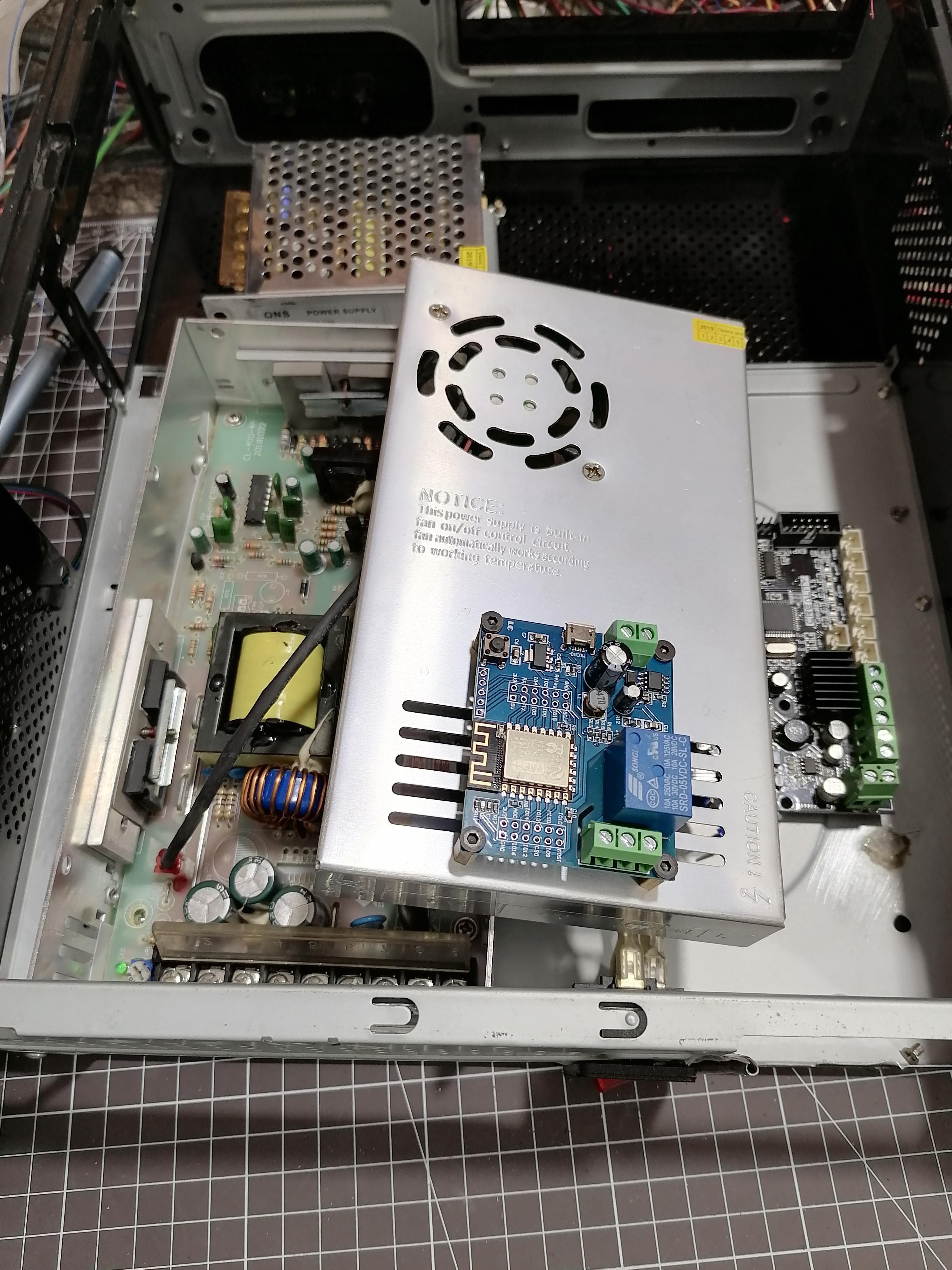
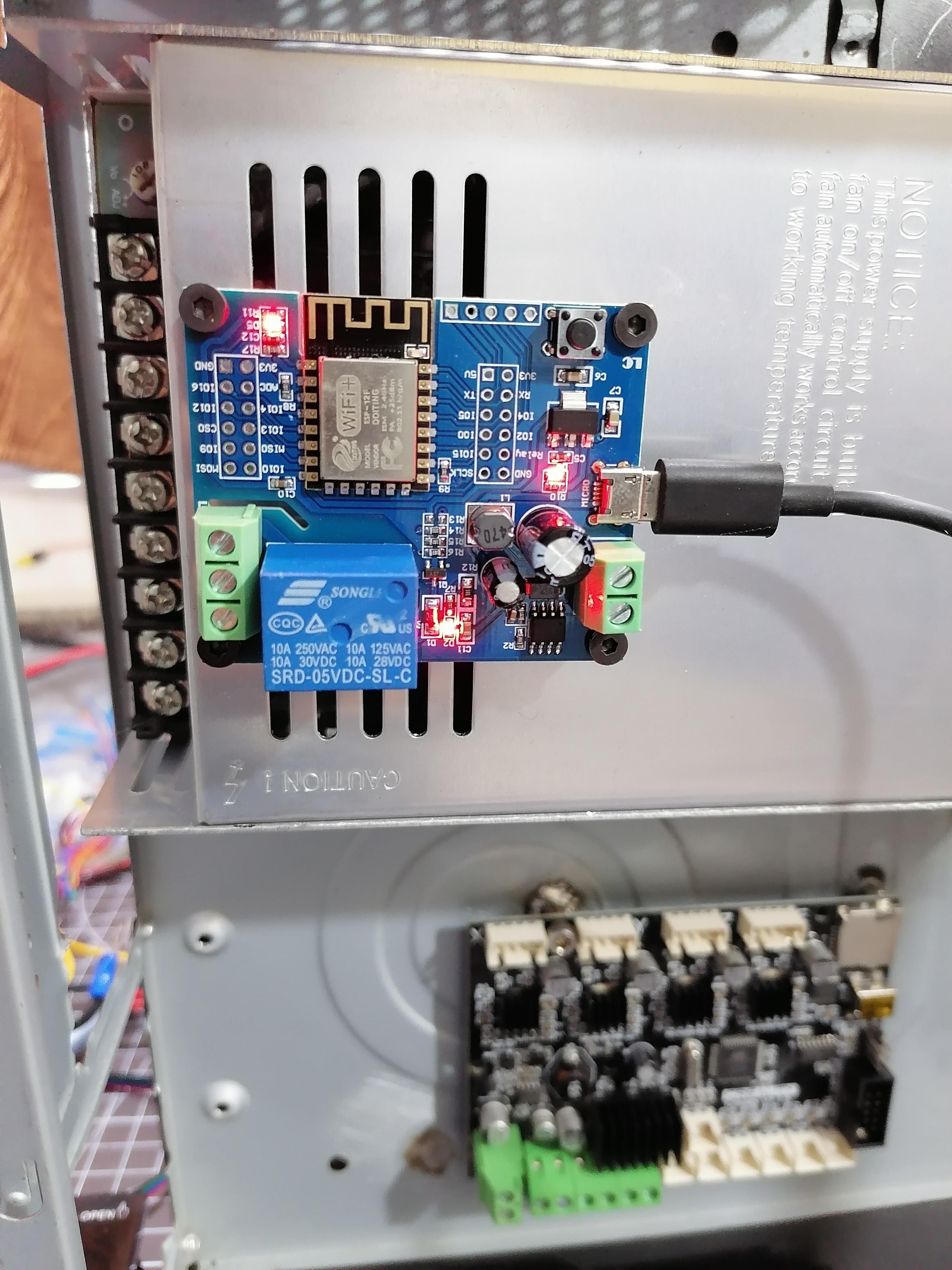
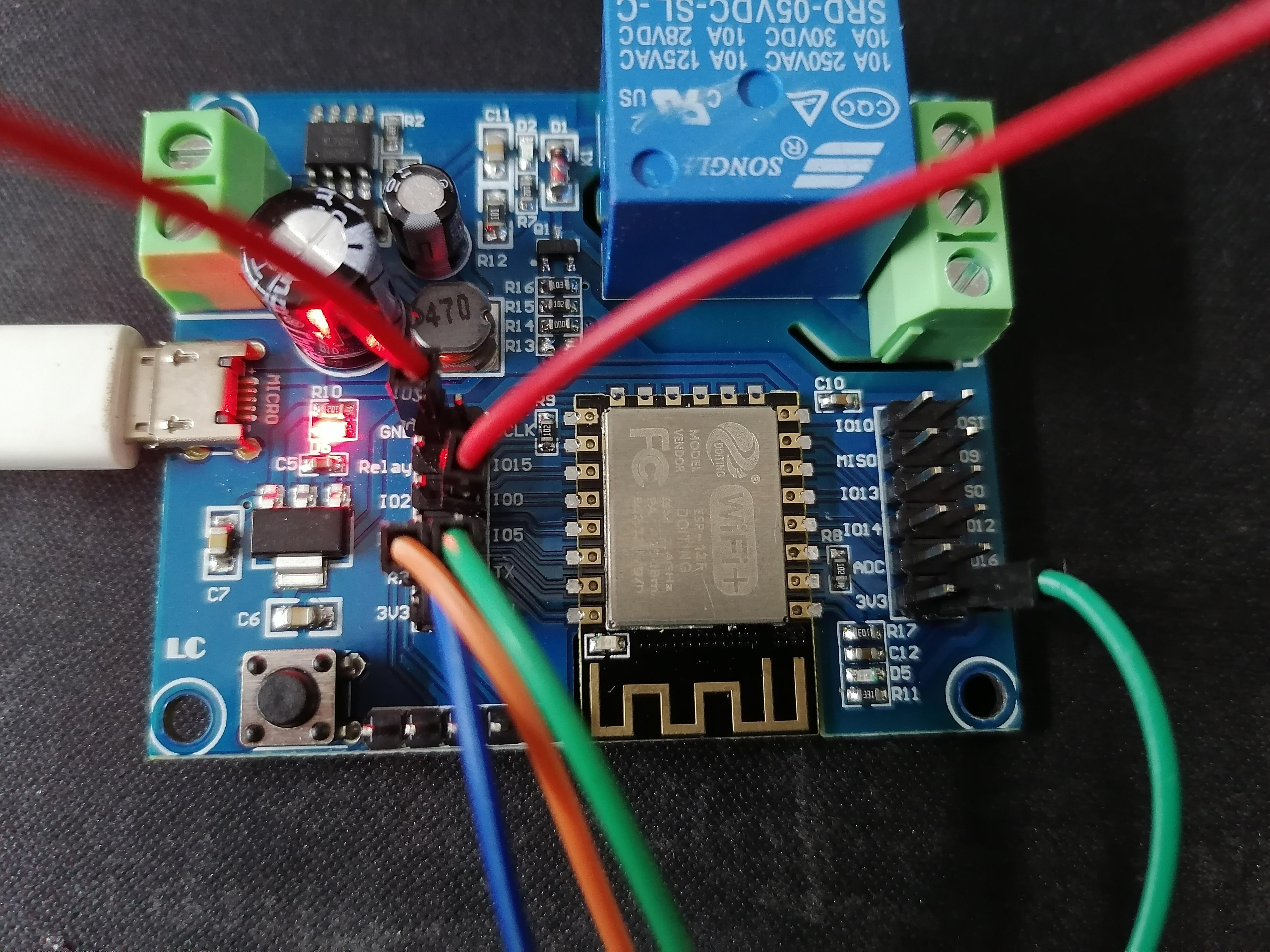
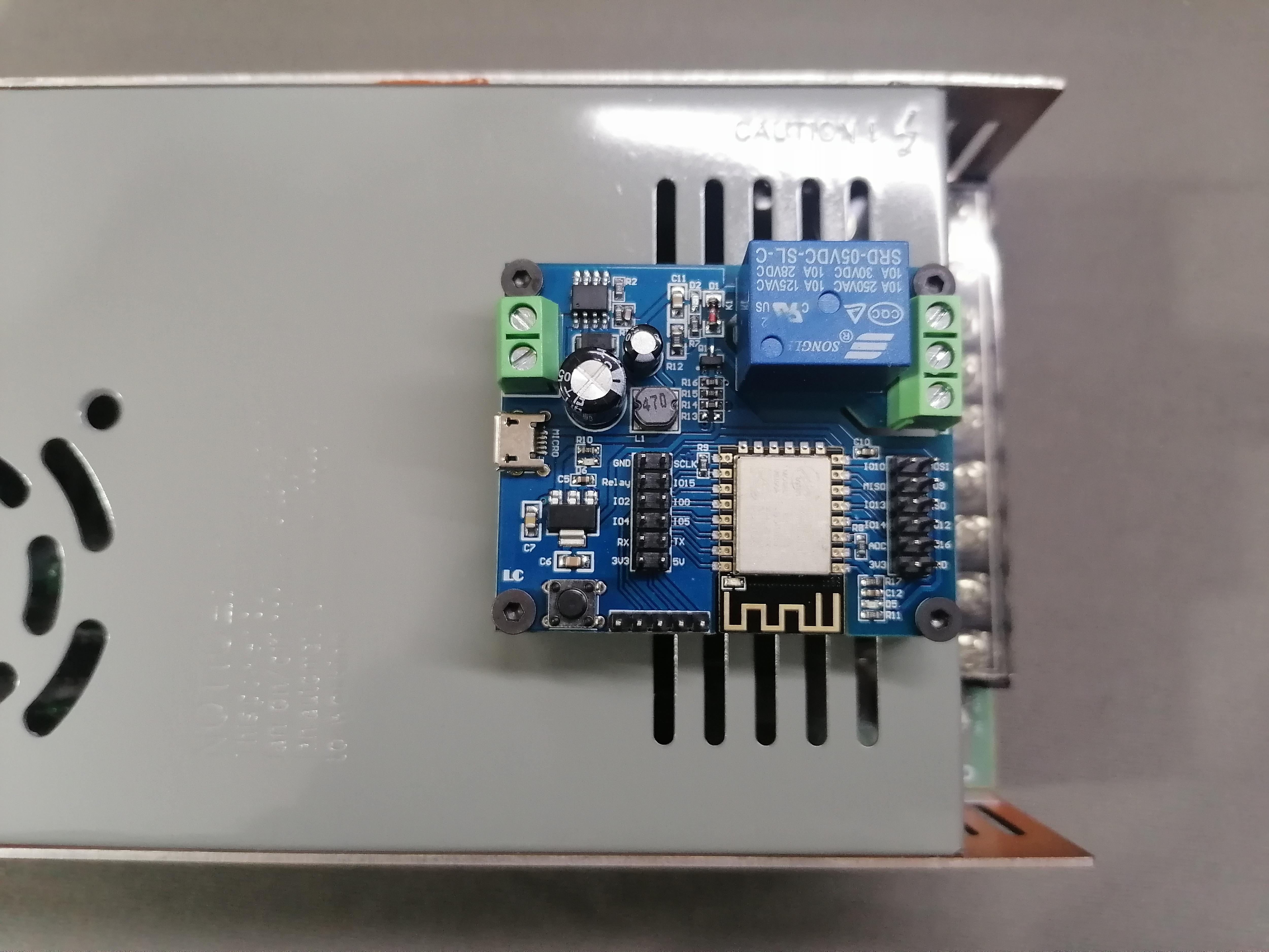
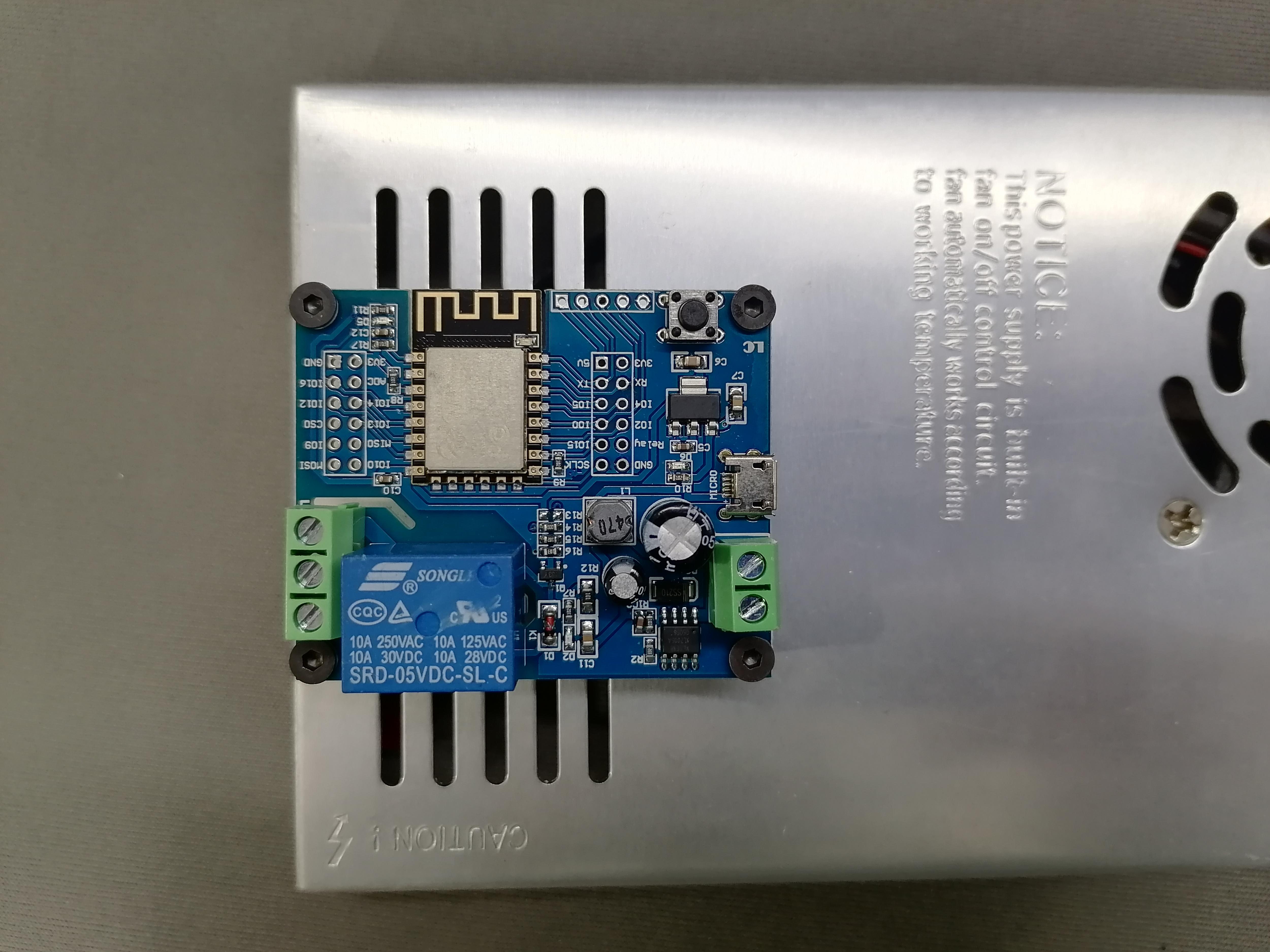
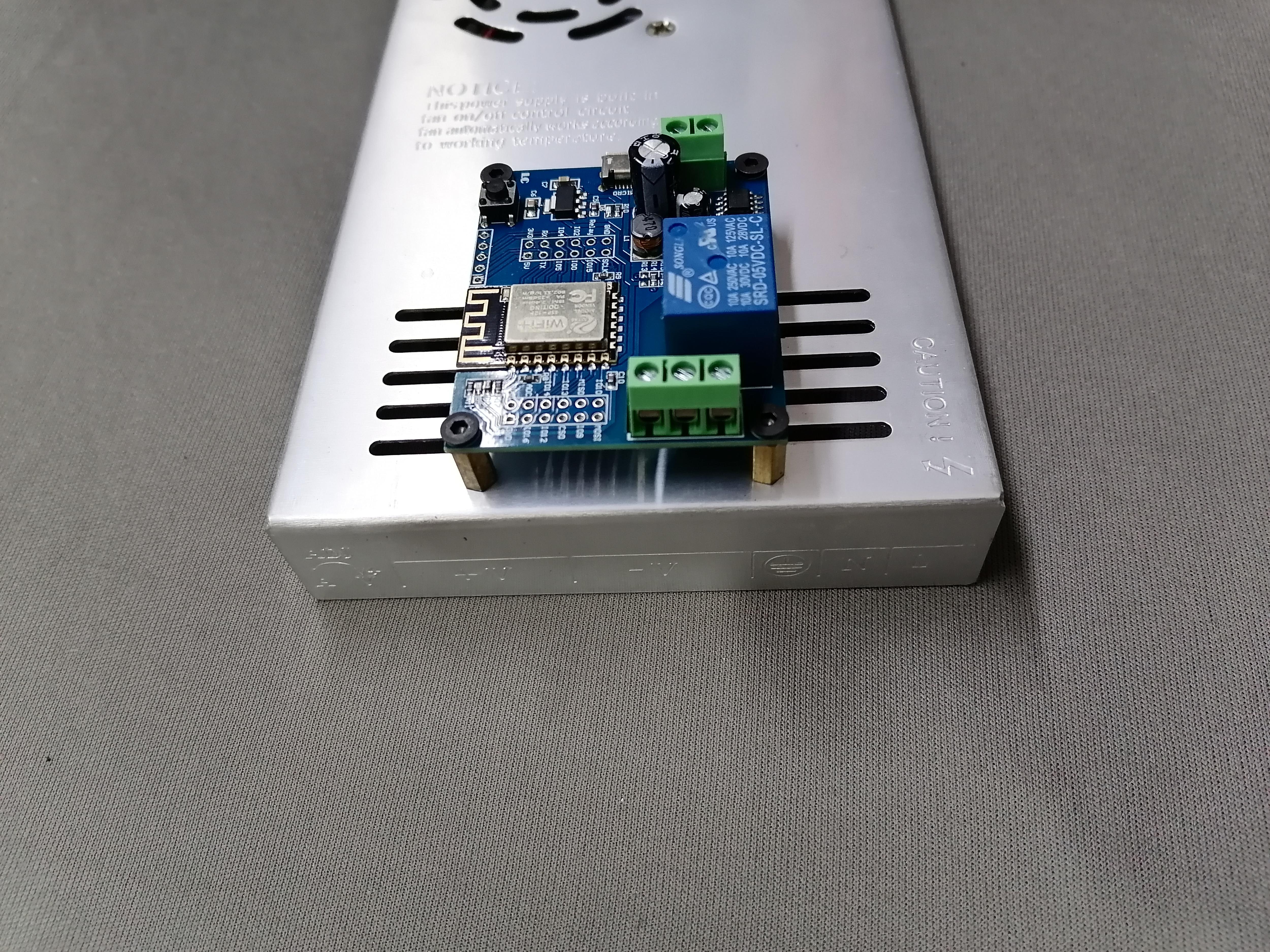

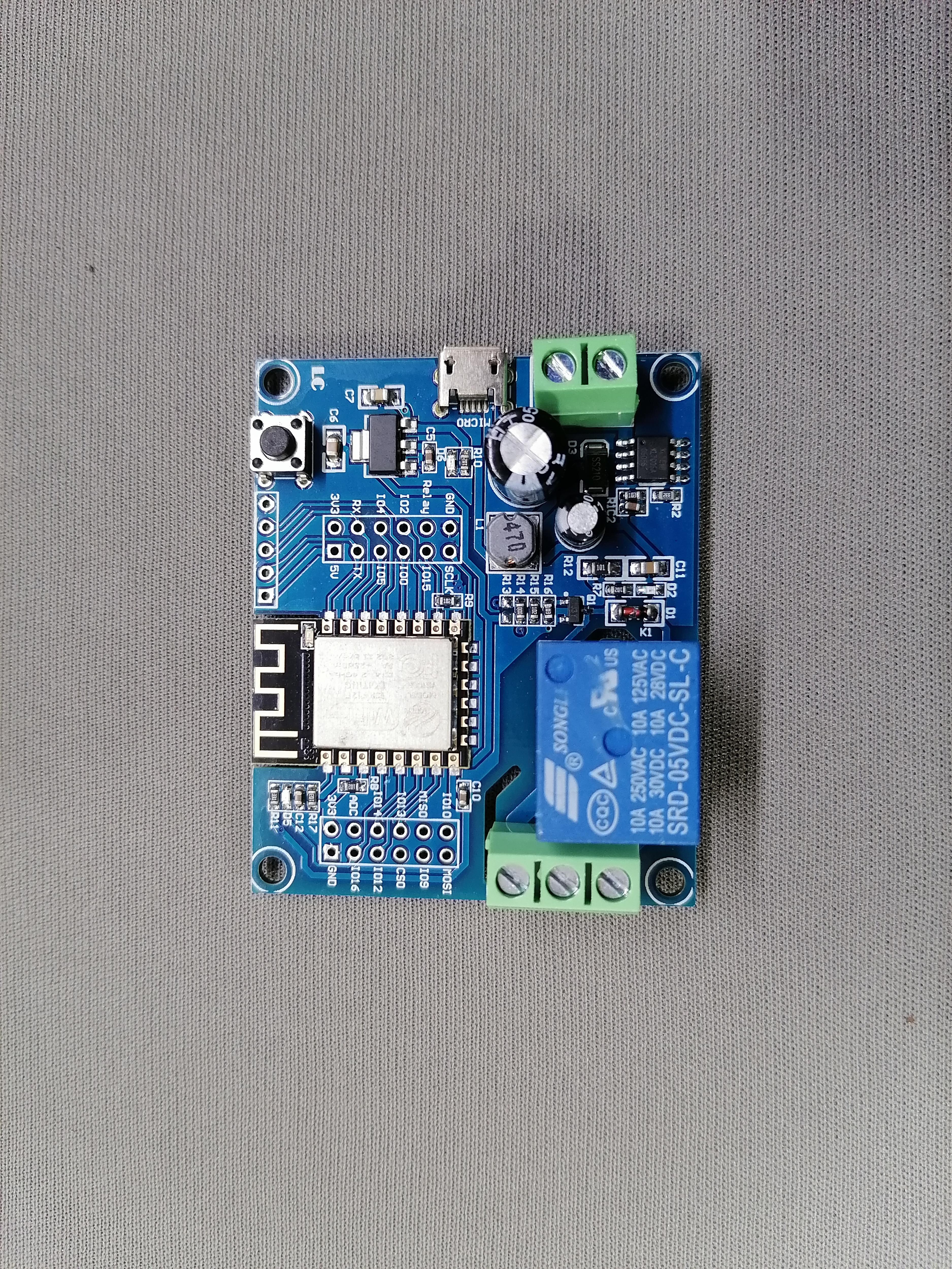
This will enable you to turn ON/OFF the 3D Printer via WiFi.
Make hole on top of the Power Supply and using Brass Male Female Screw attach the WiFi Relay module on SMPS.
Also upload the program on WiFi Relay module.
Here I am attaching the program code, download and upload using Arduino IDE.
This step is optional if you do not want use the WiFi turn ON/OFF the 3D Printer.
Downloads
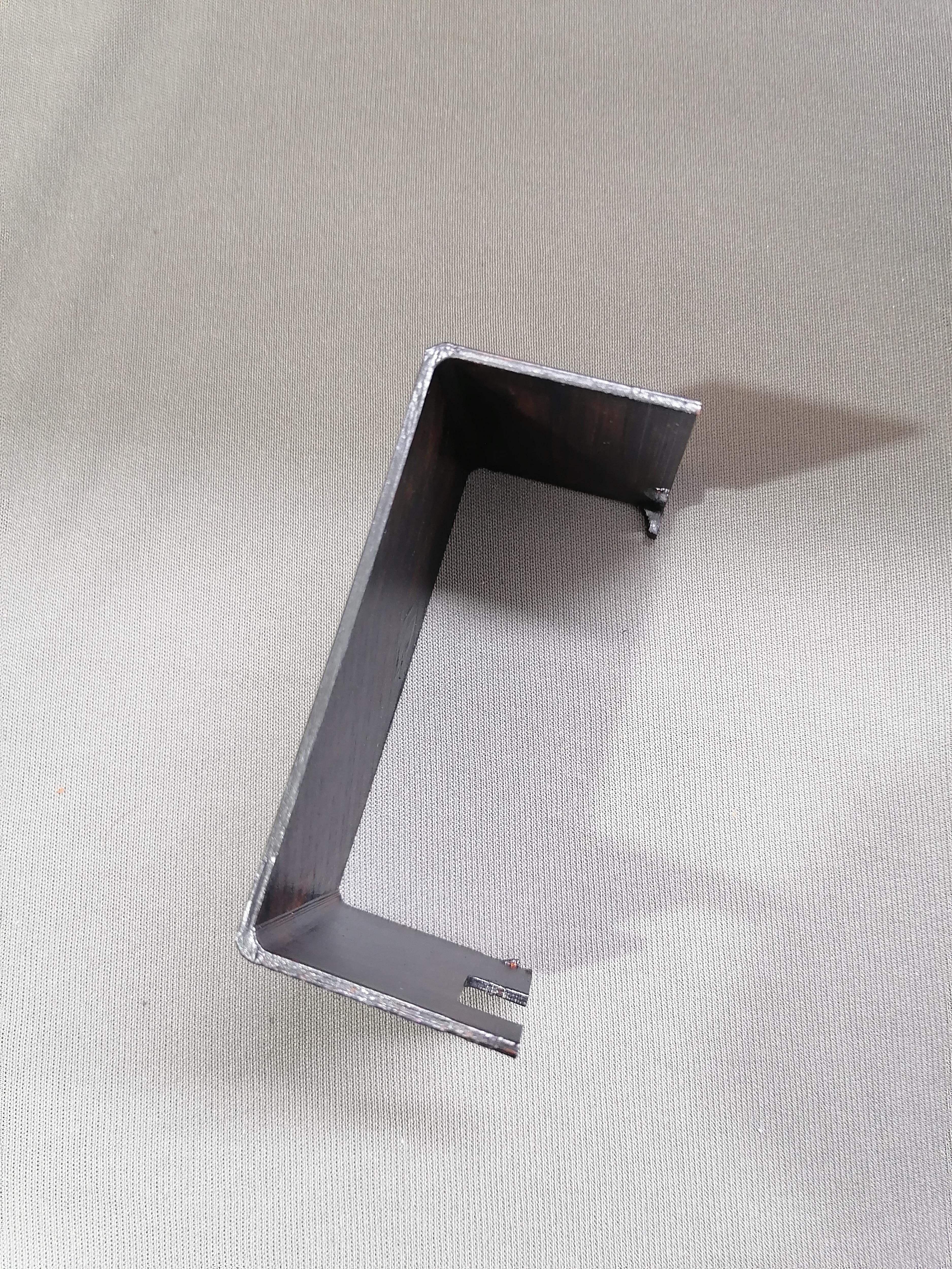
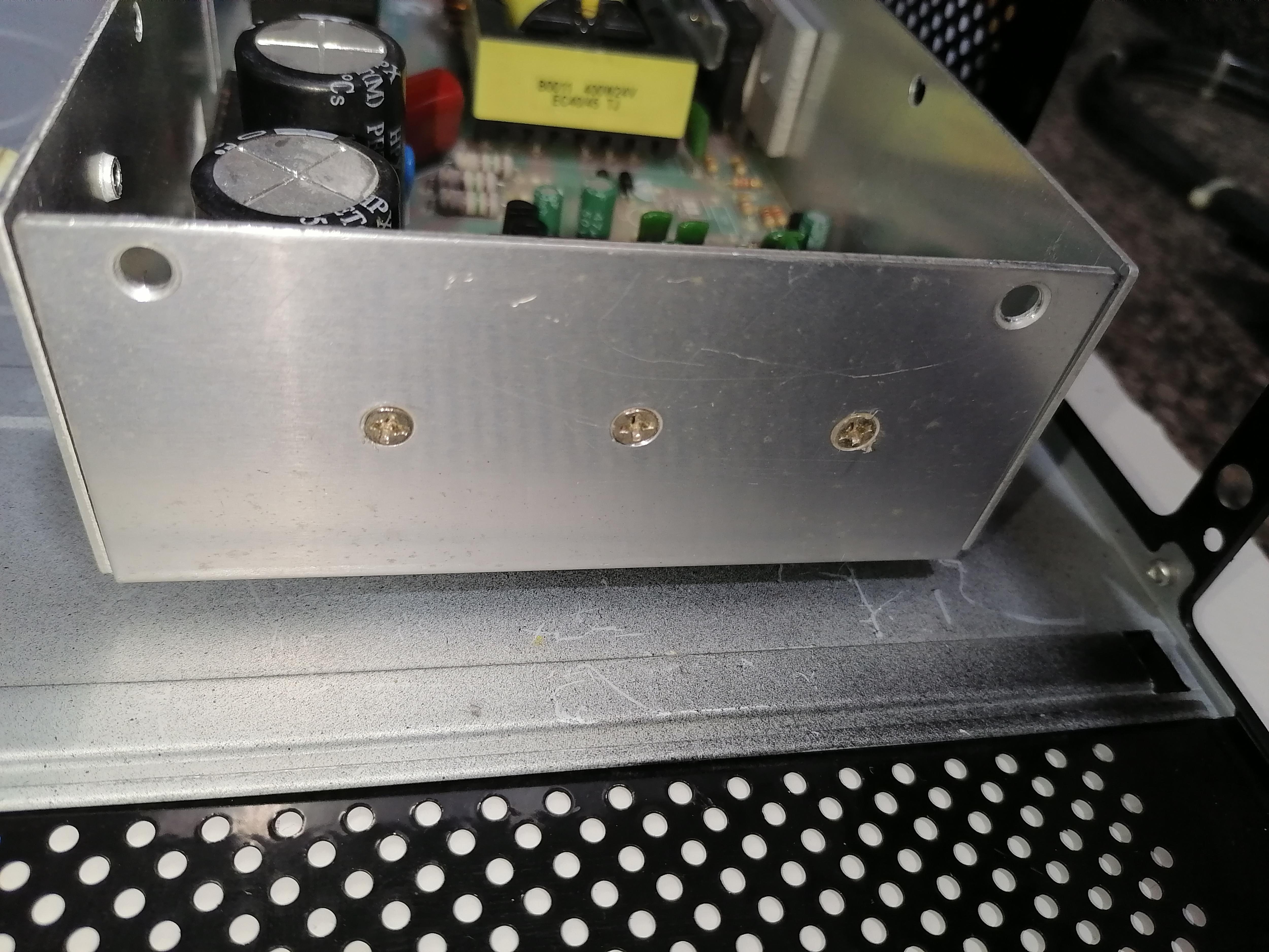
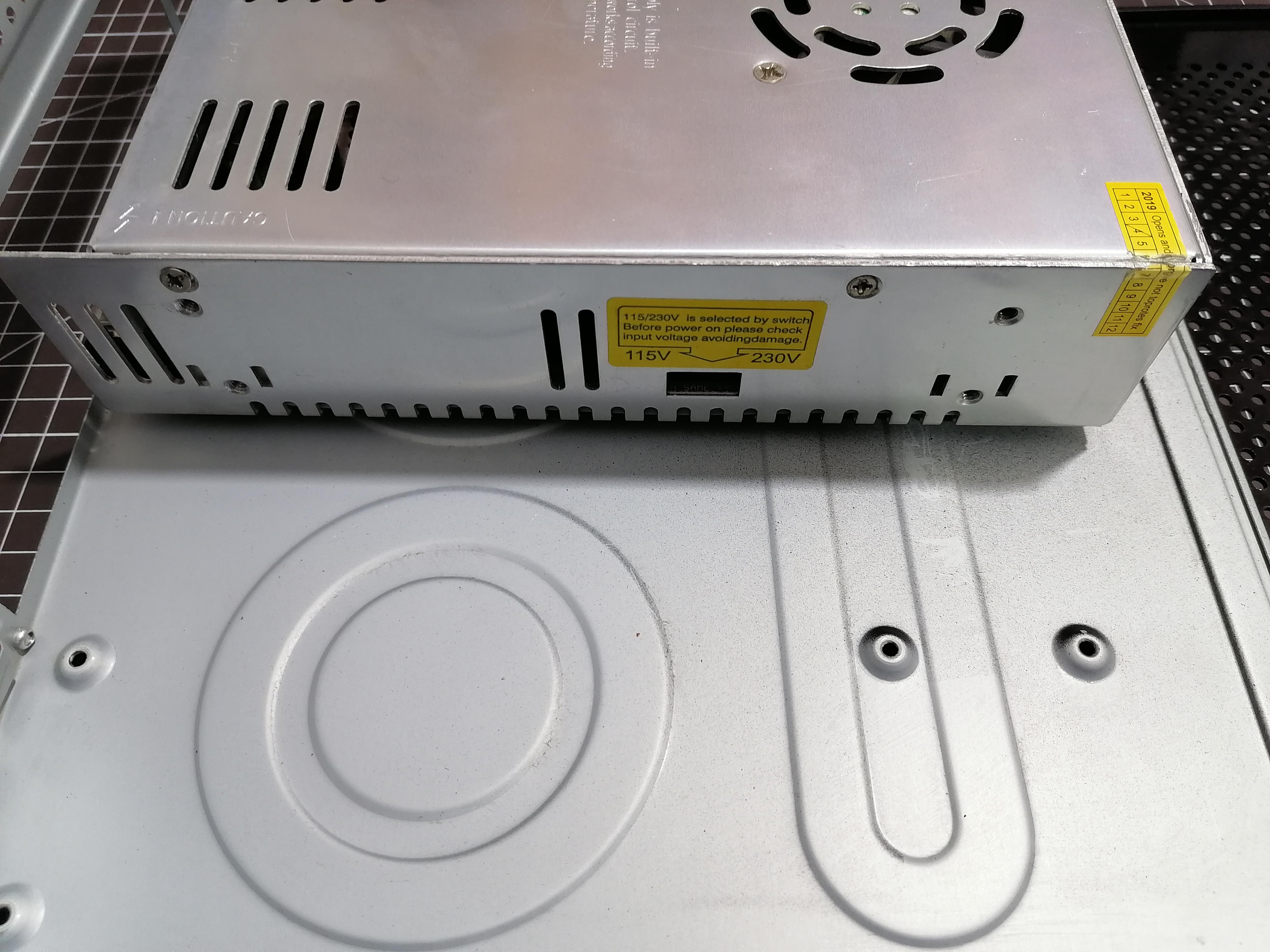
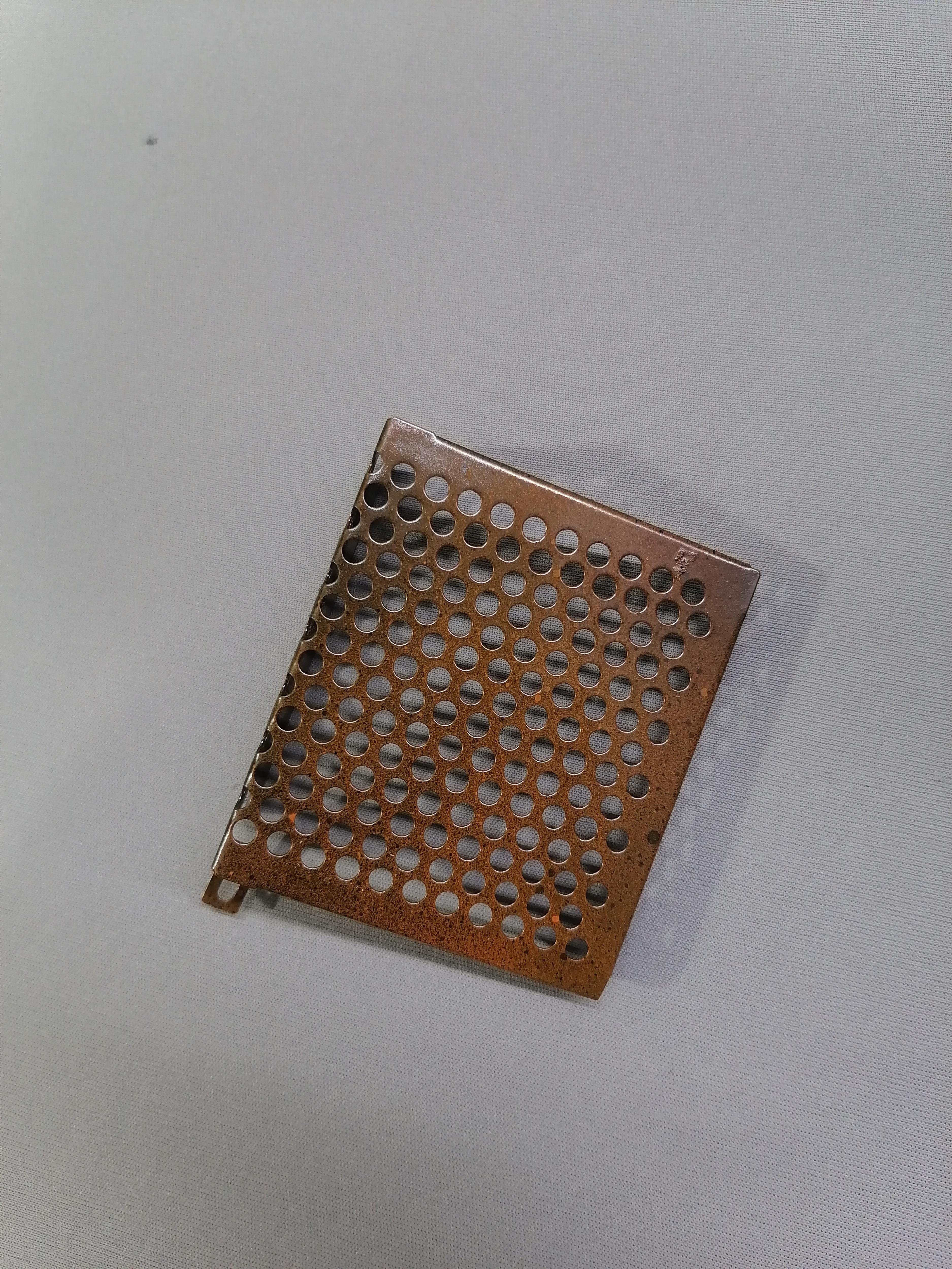
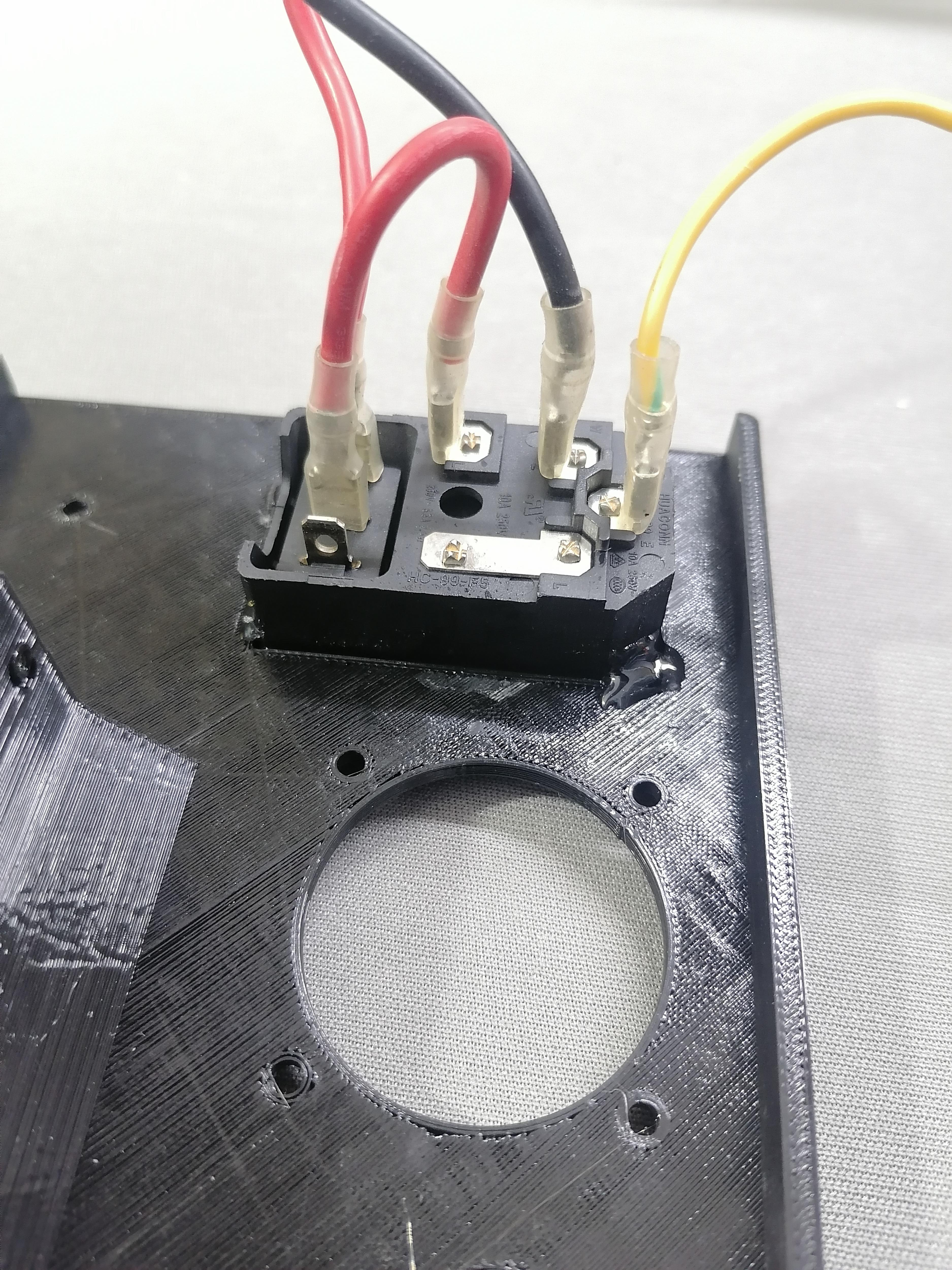
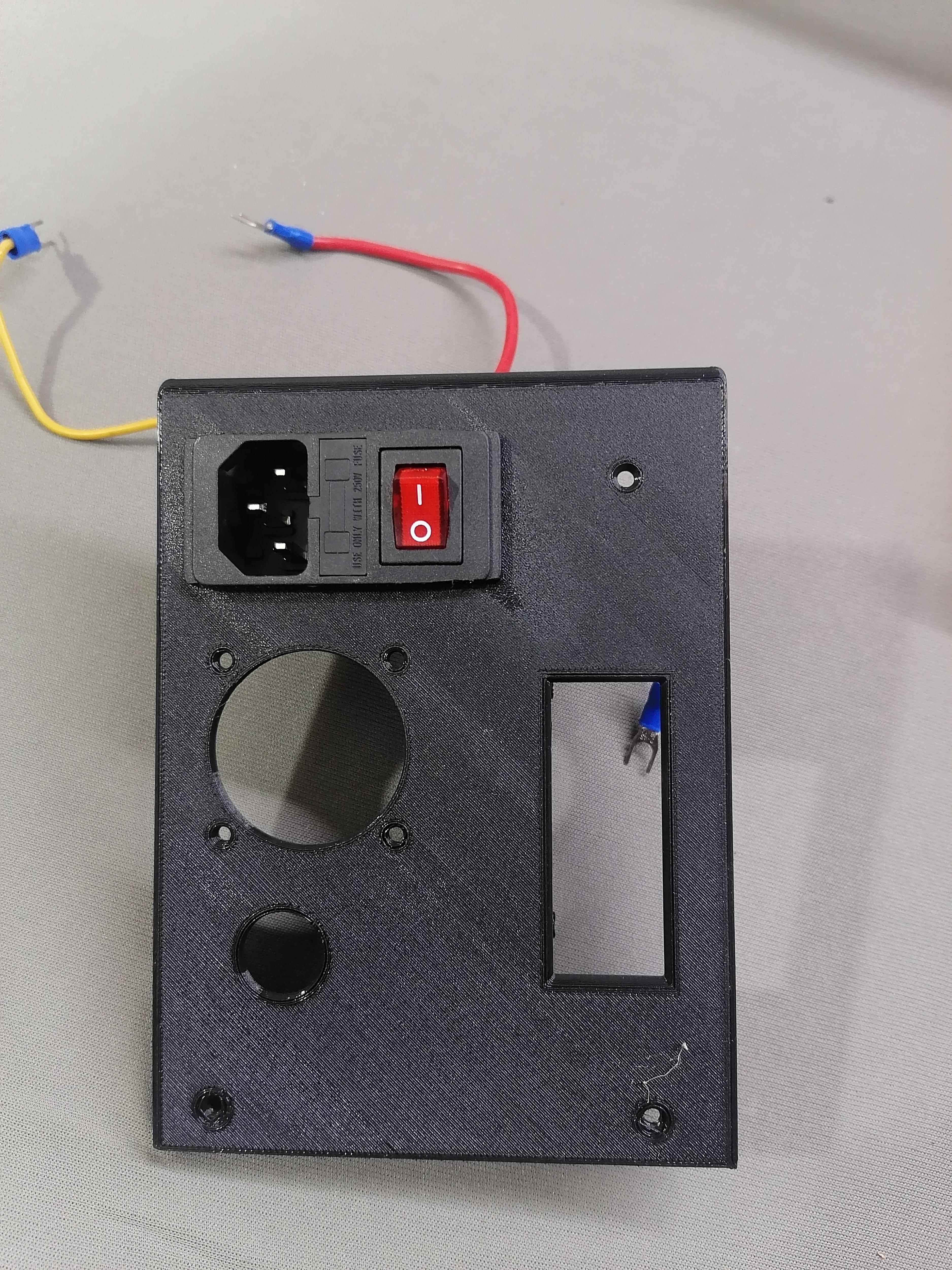
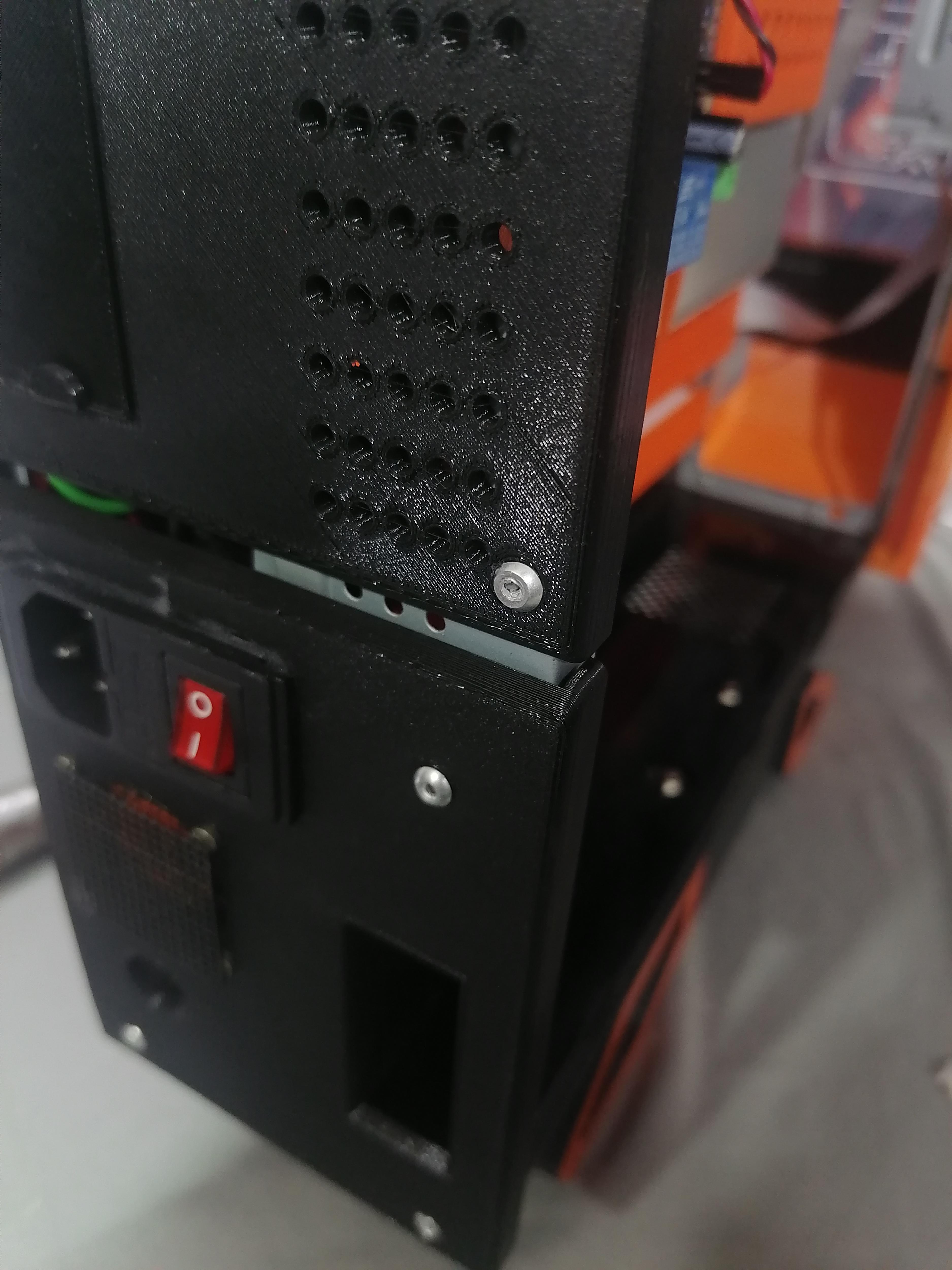
Cutting Extra Part of Supply Switch of Power Supply
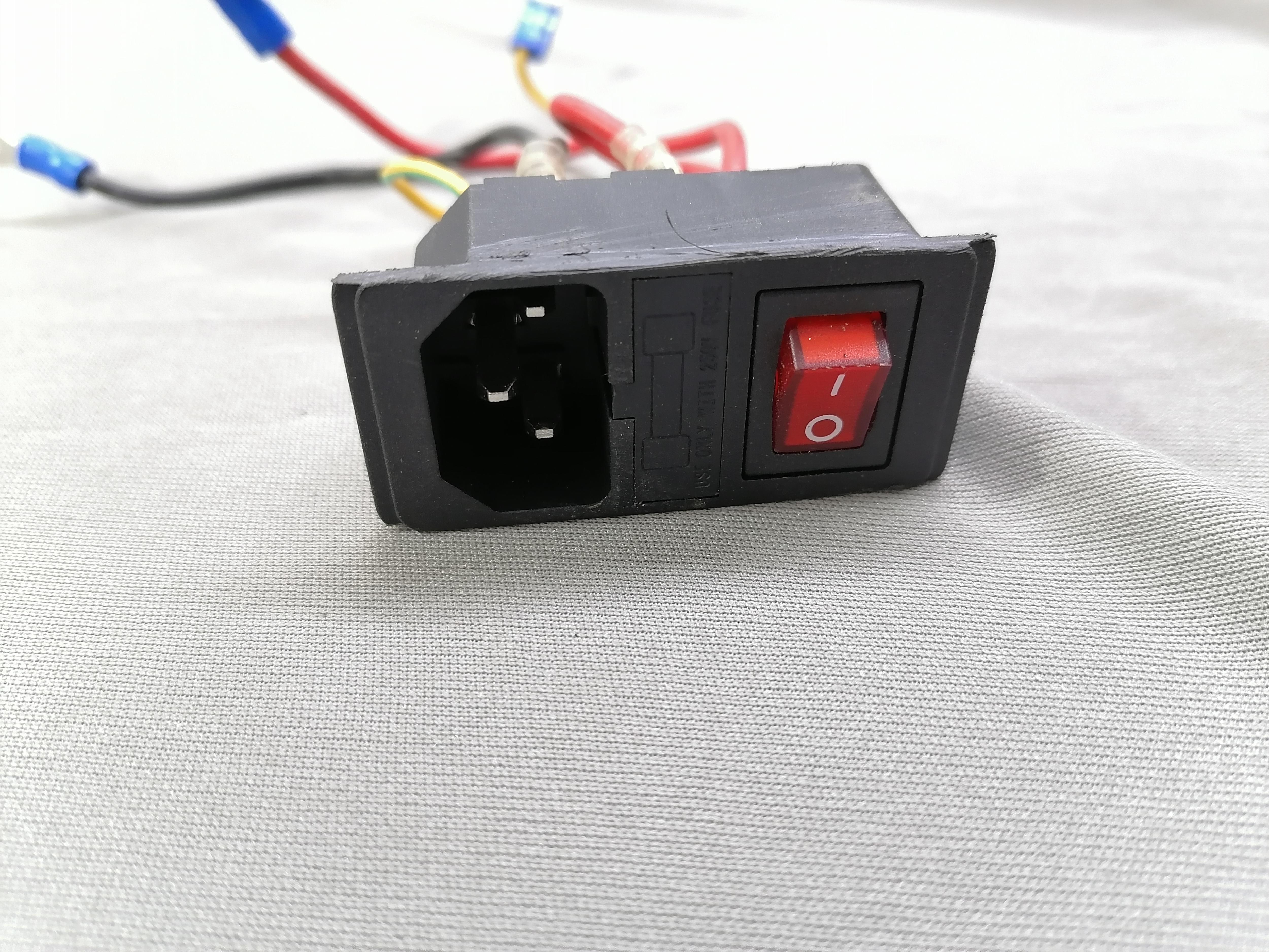
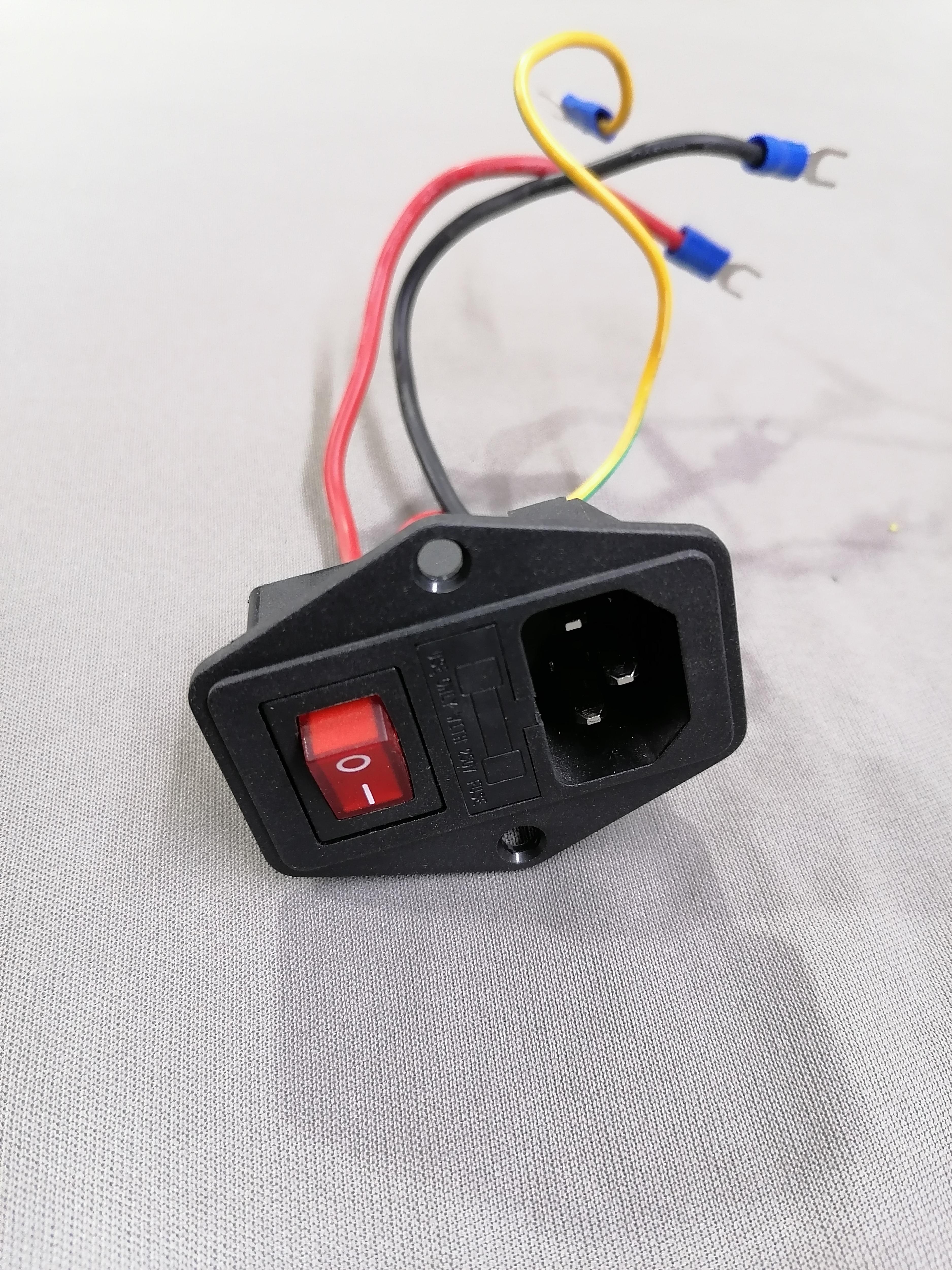
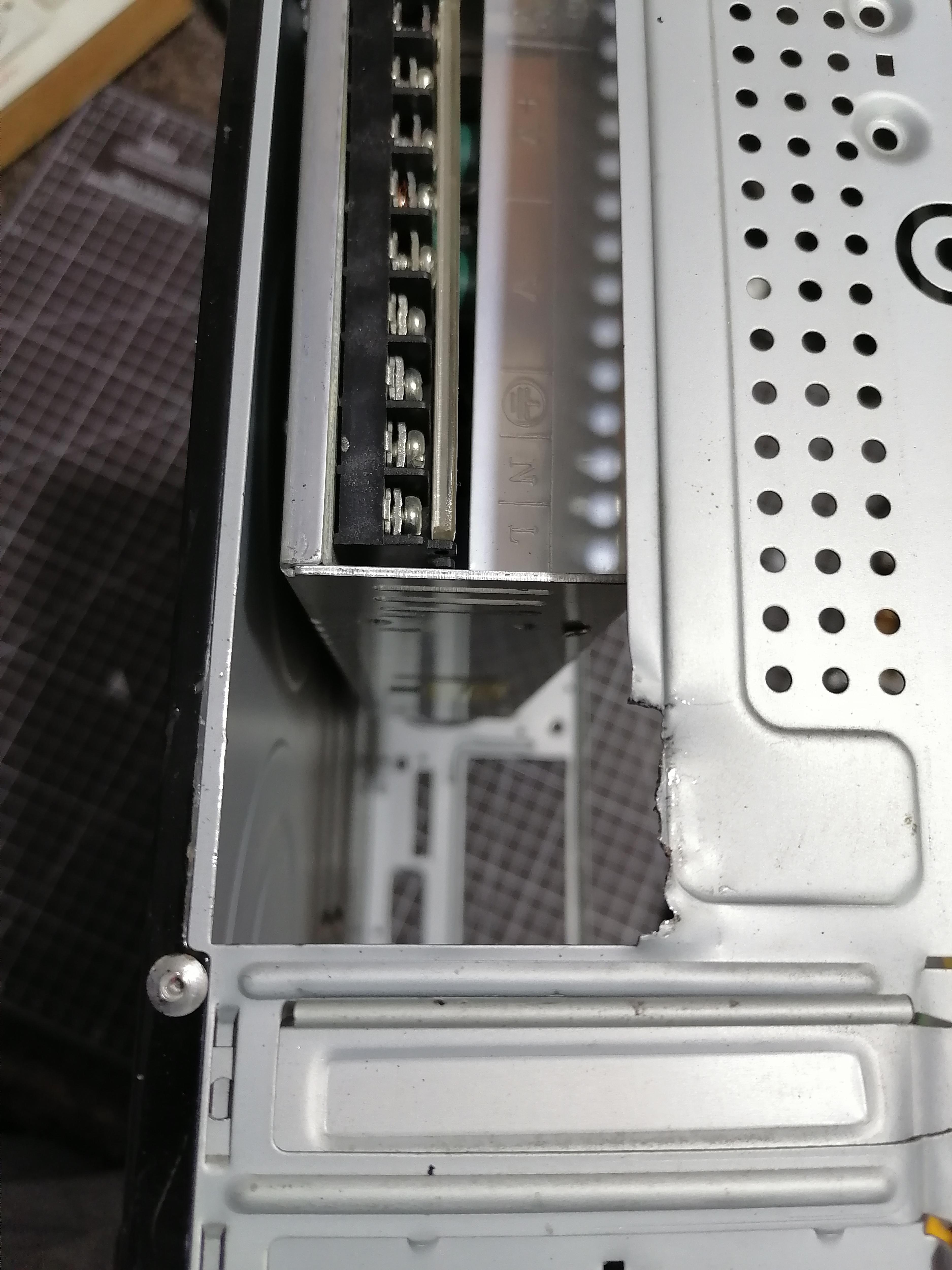
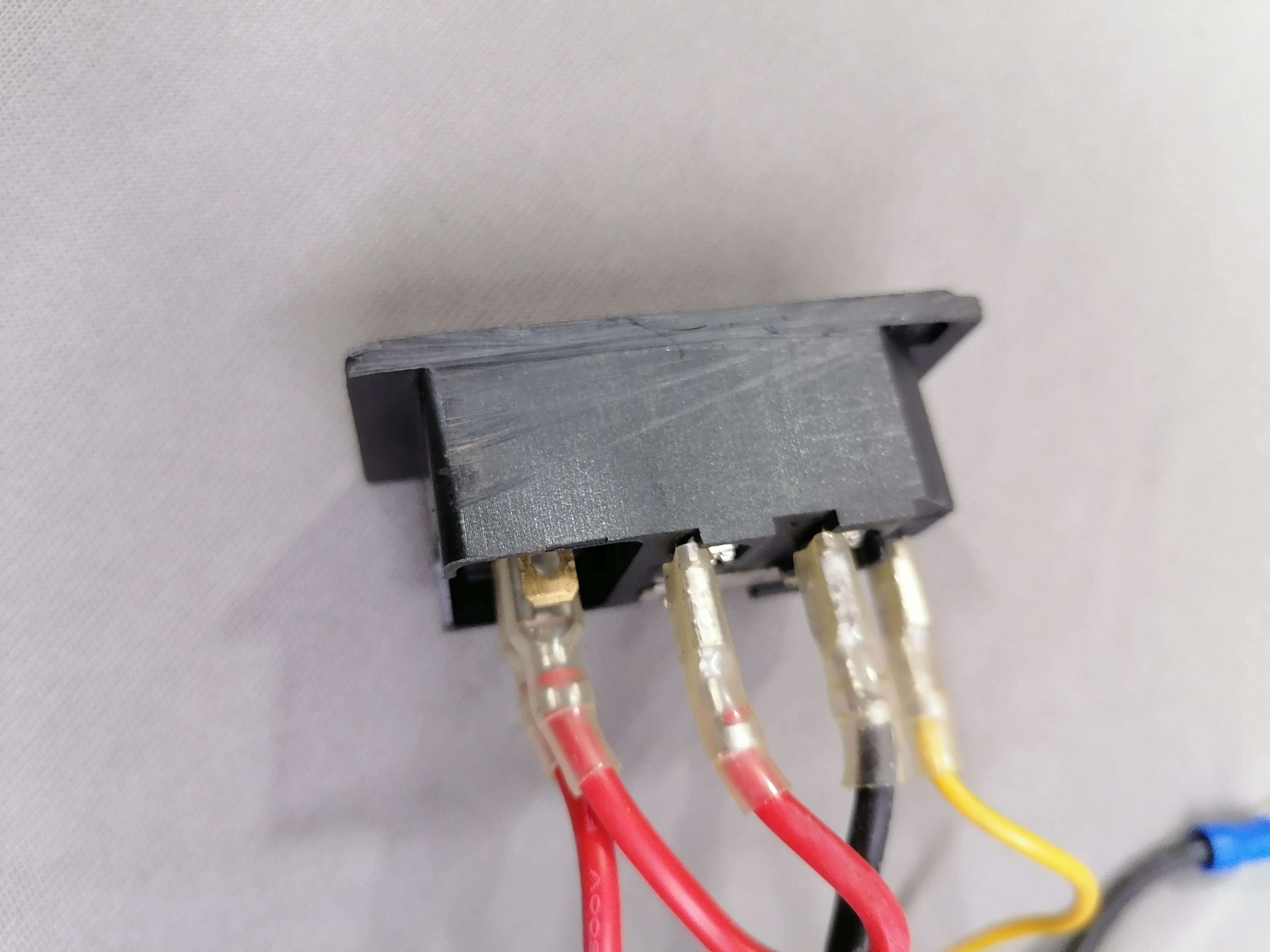
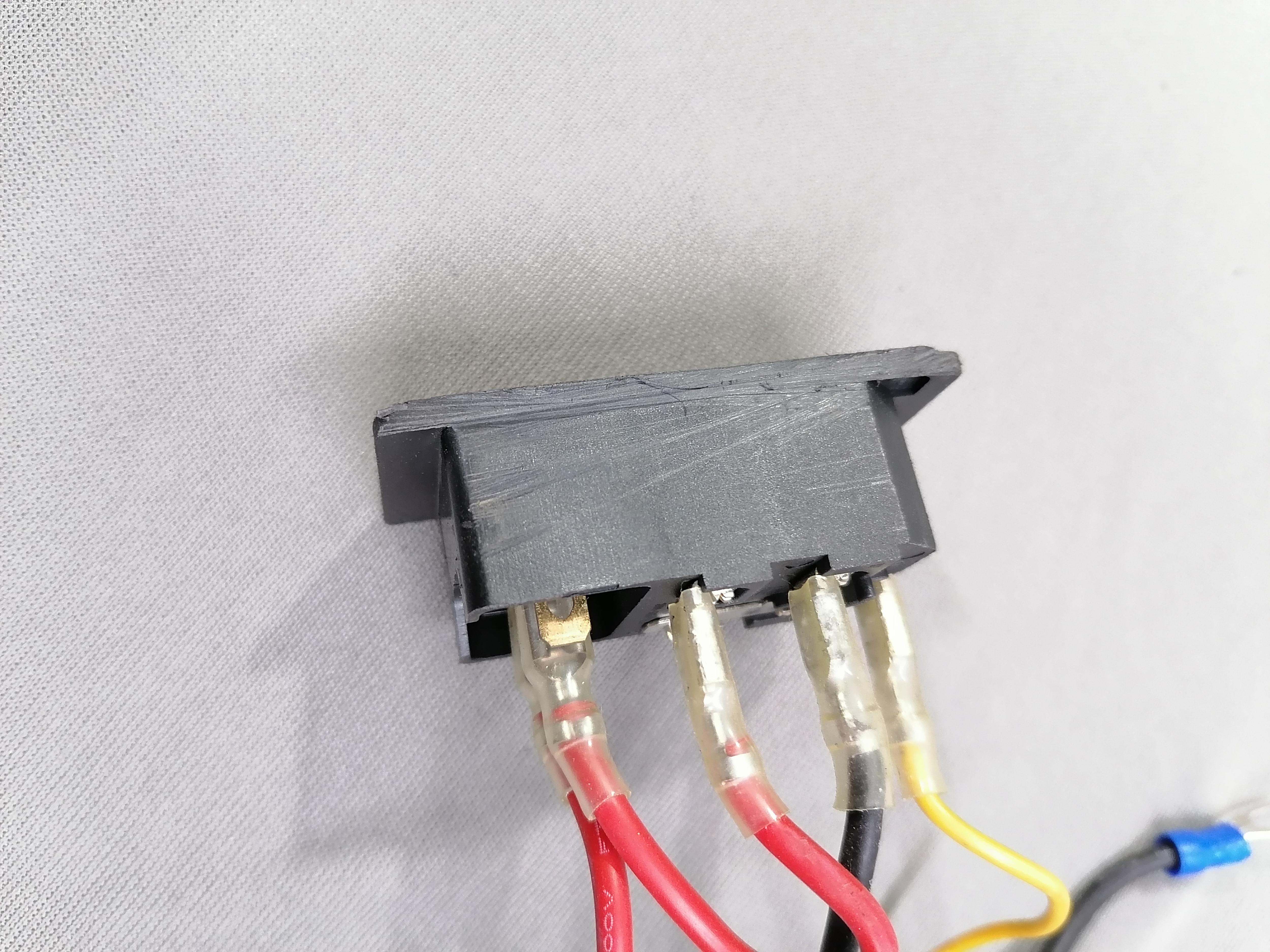
Refer the image for how to cut the switch extra part and also make cut similar at back of CPU where it need to be inserted.
Also cut the metal part of back of CPU Case.
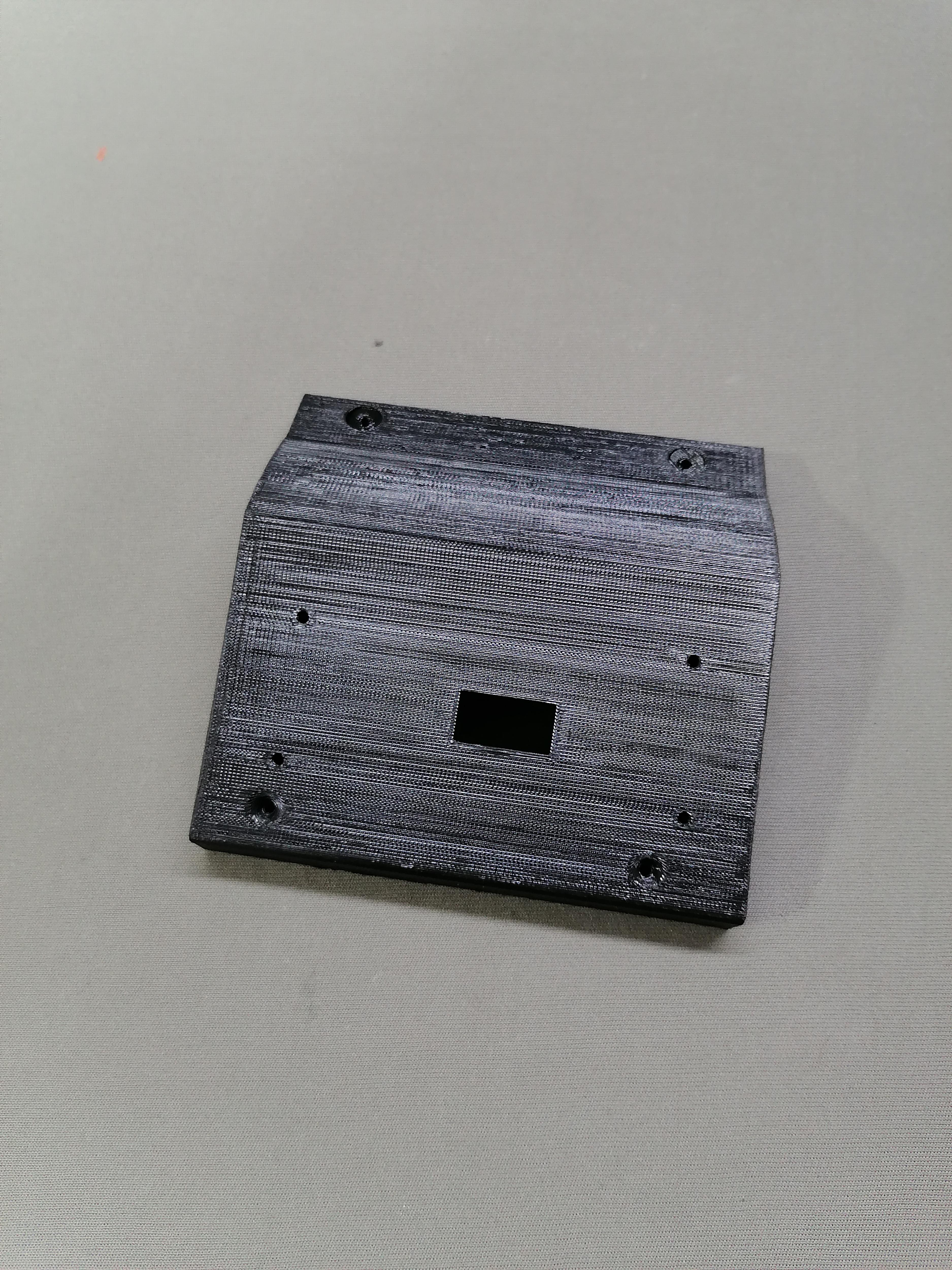
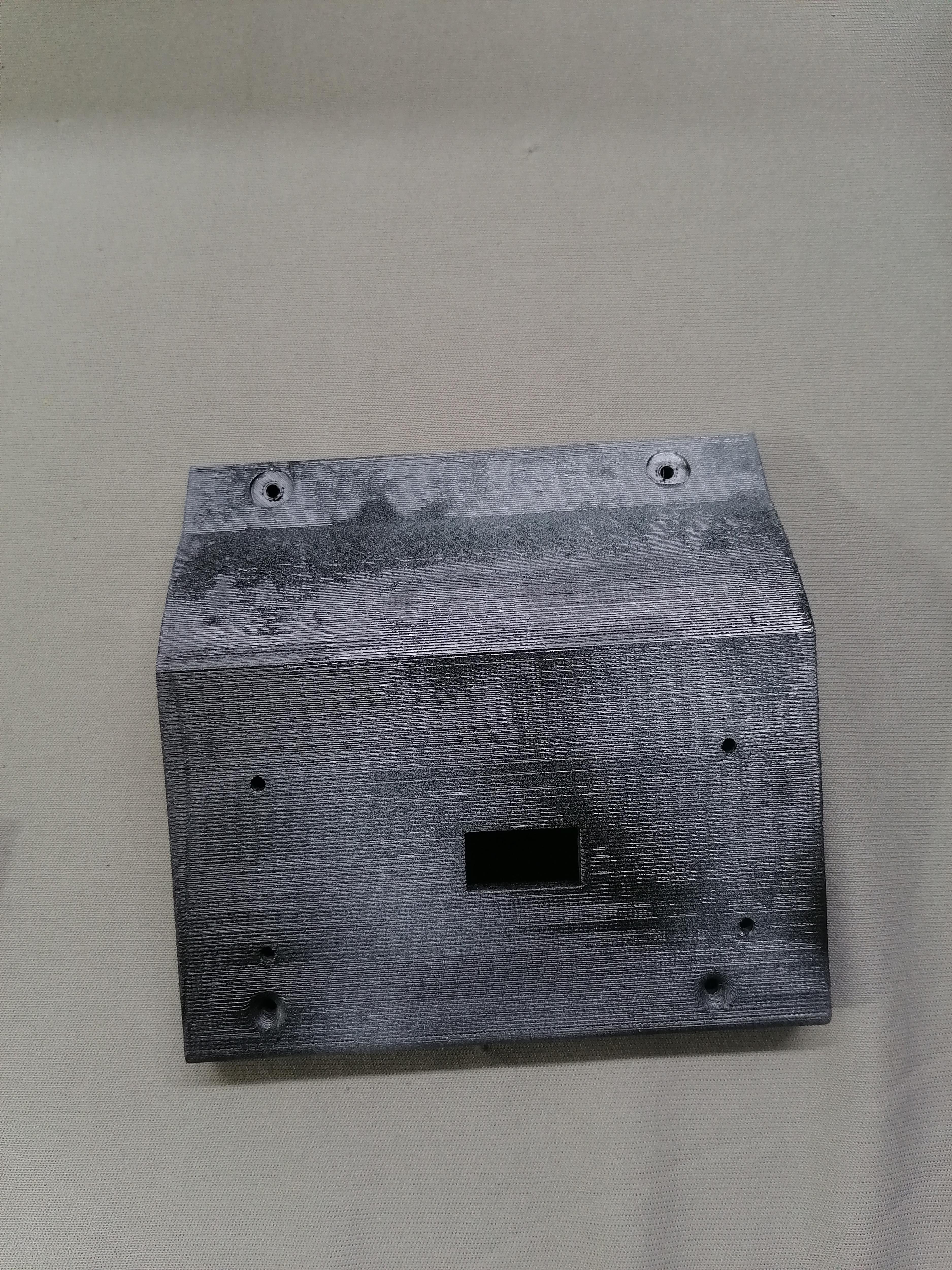
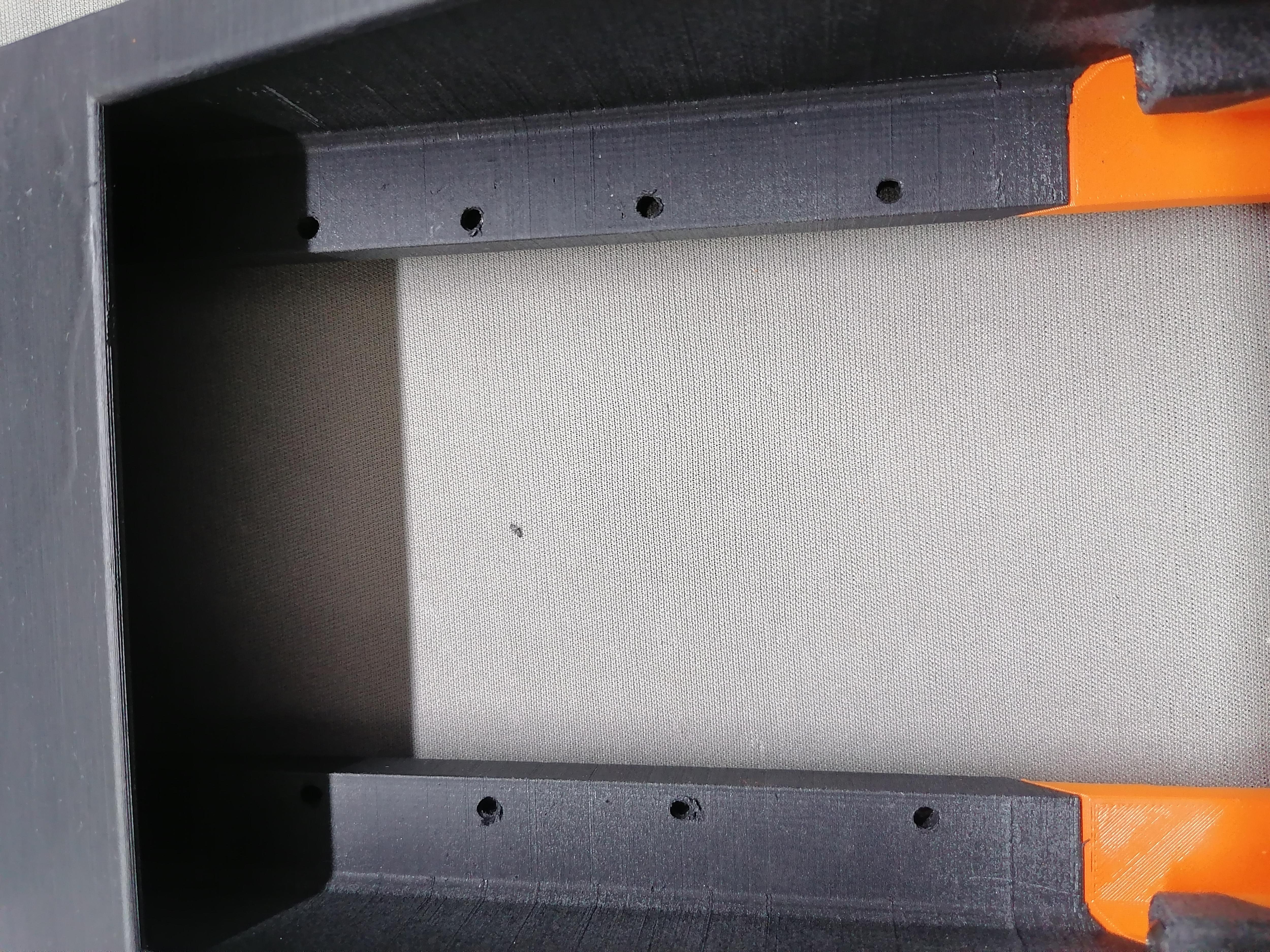
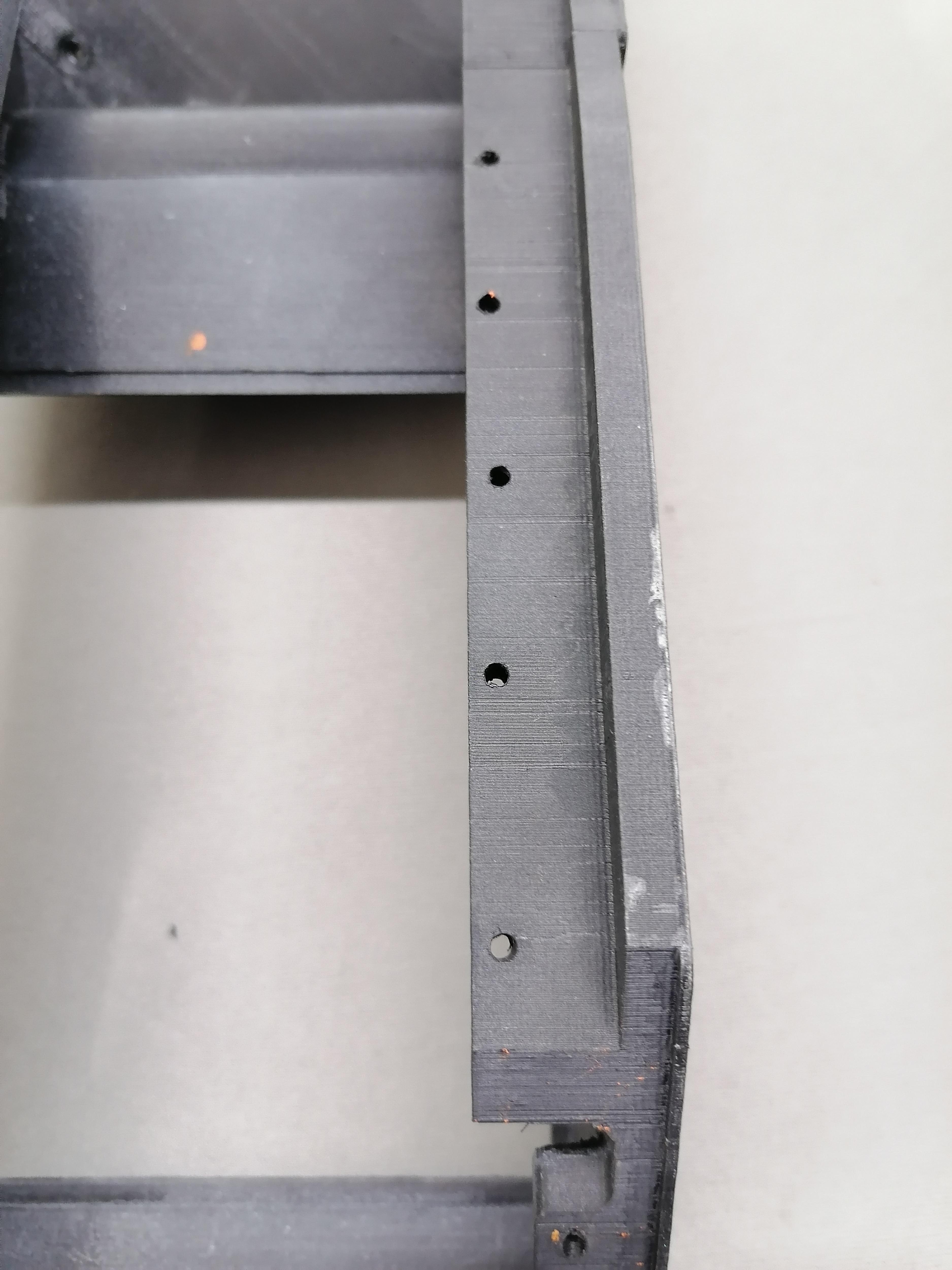
Mark the Hole of Base Stand on CPU Bottom and Then Make Hole

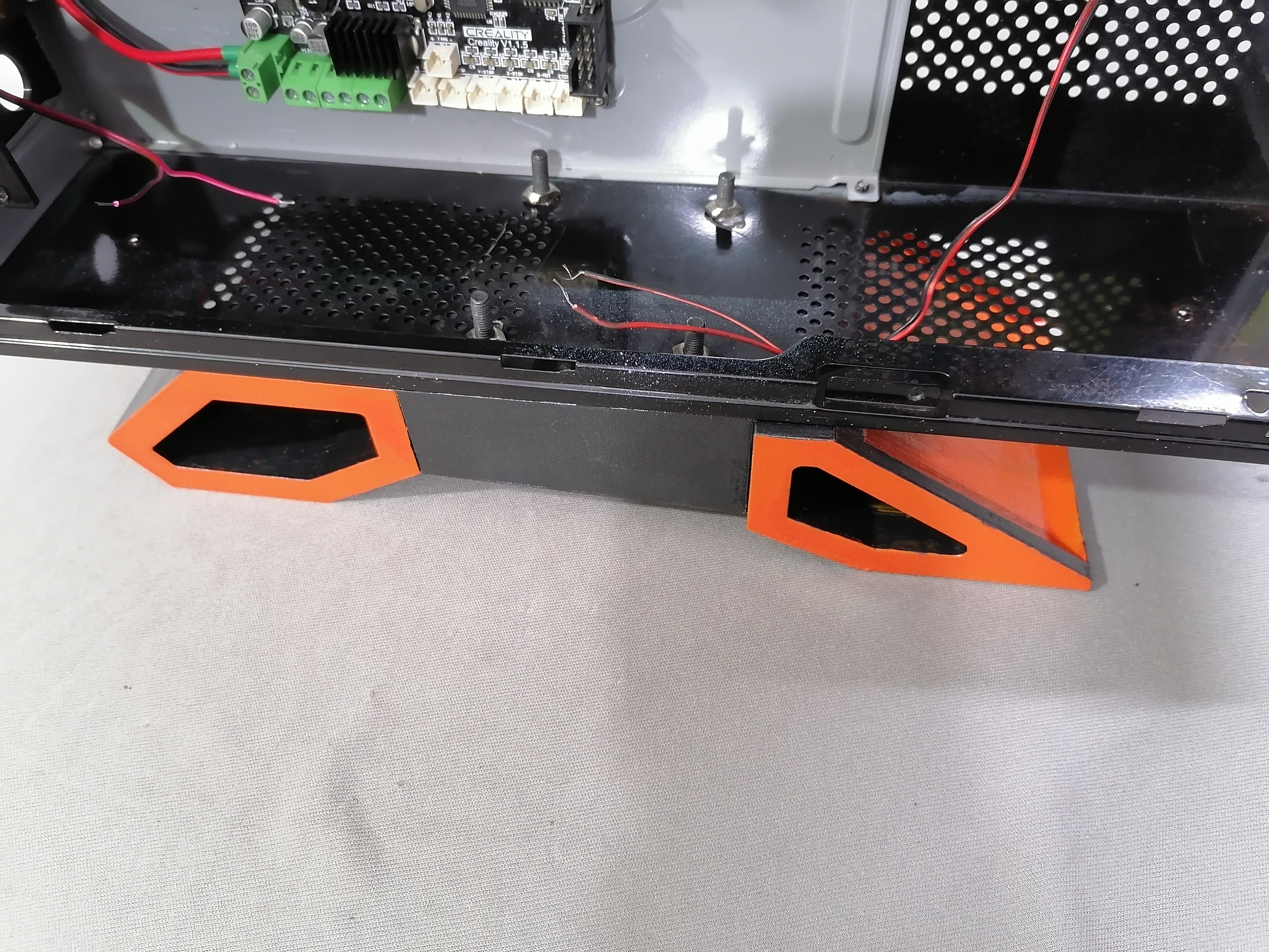
Mark the hole of base stand on CPU Bottom and then make holes.
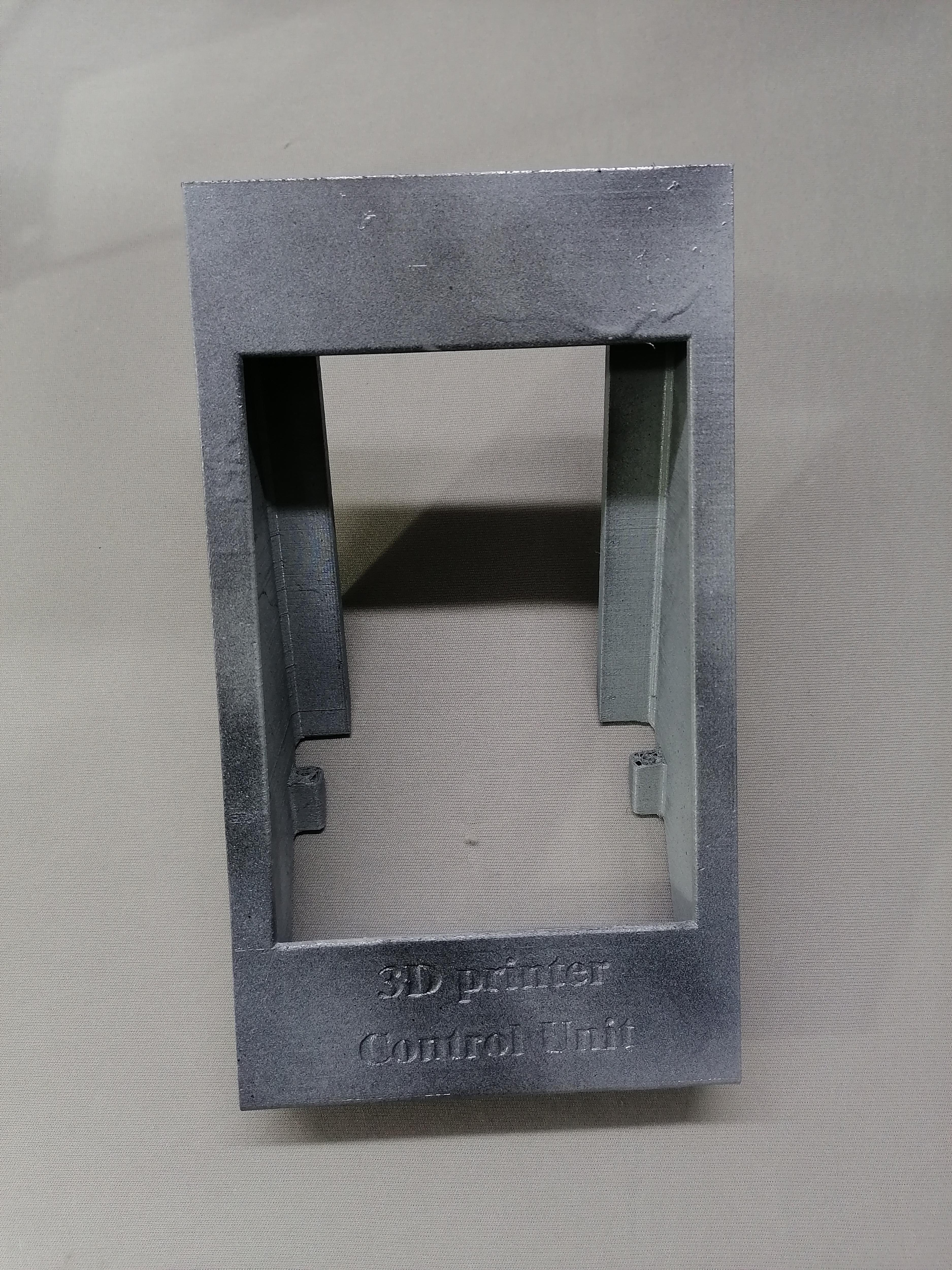
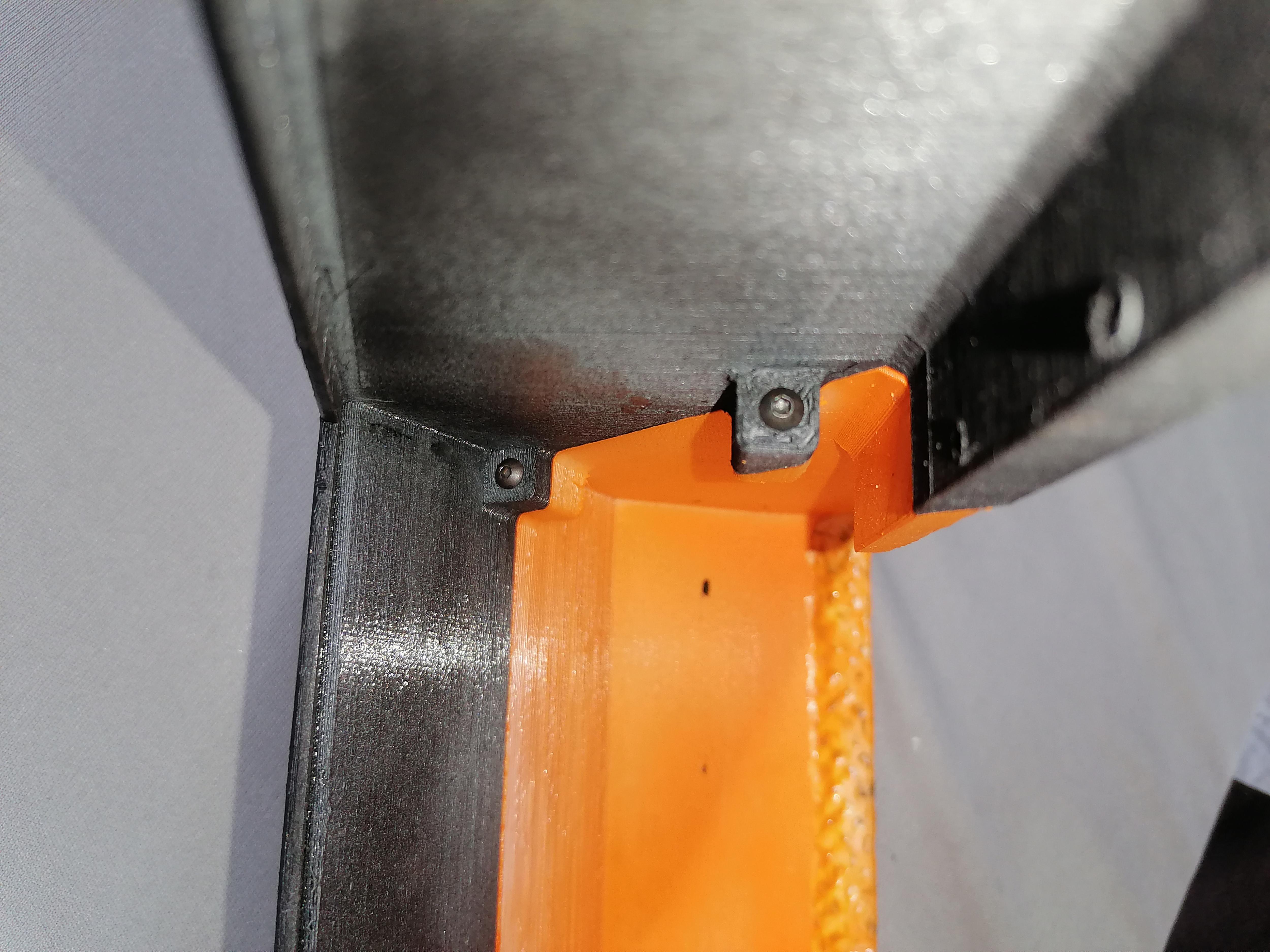
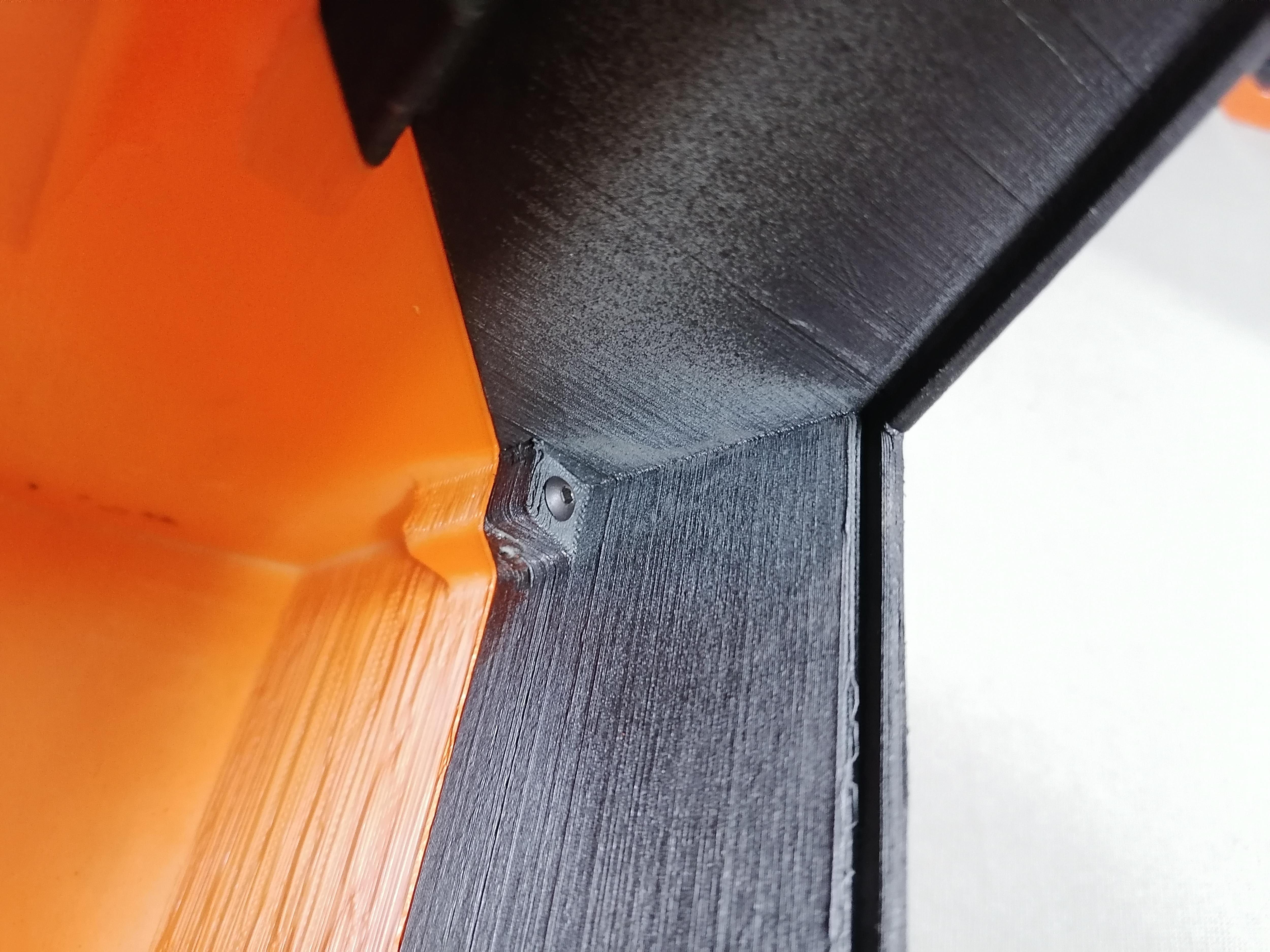
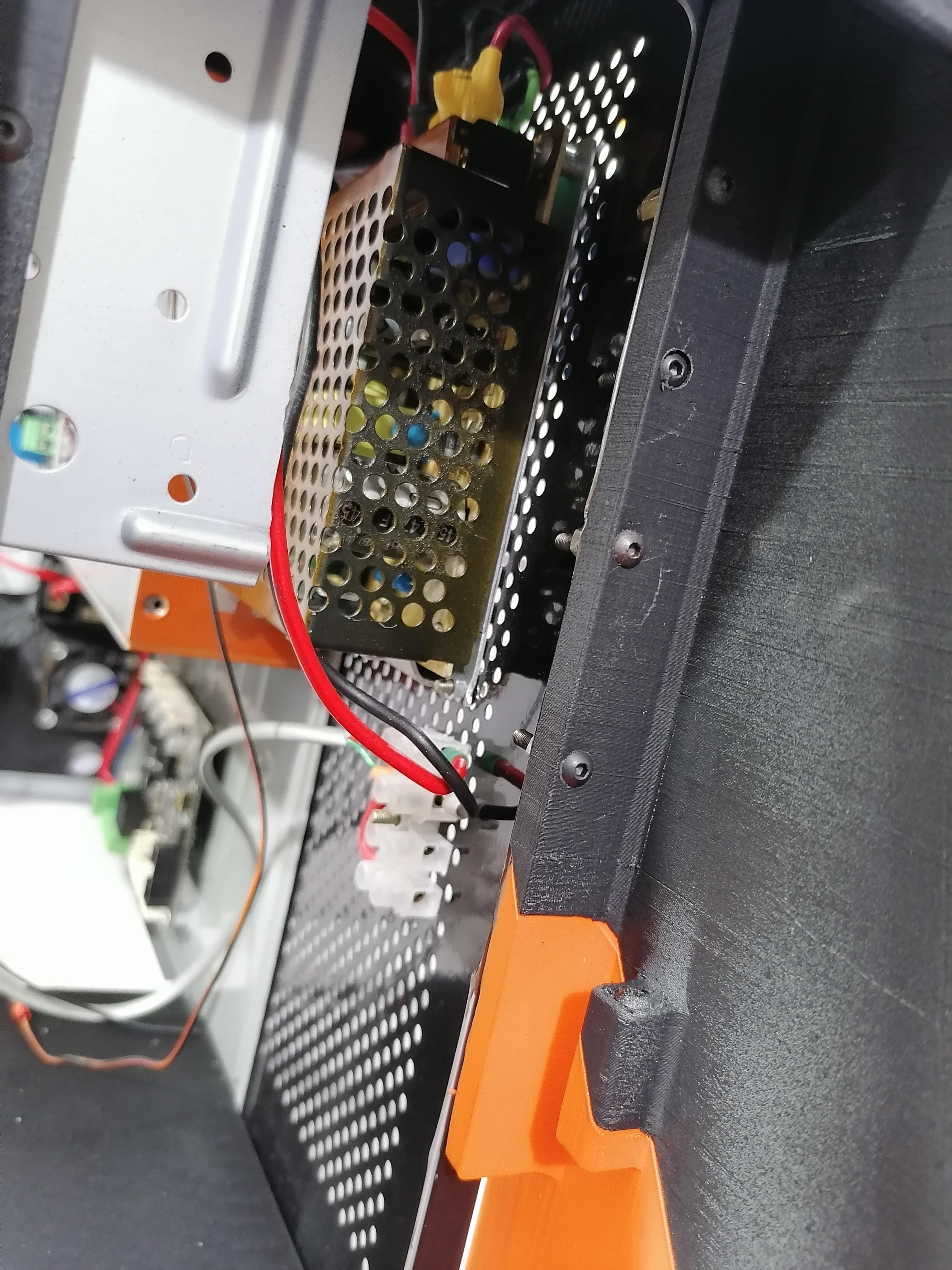
Attach the Base Stand to the CPU


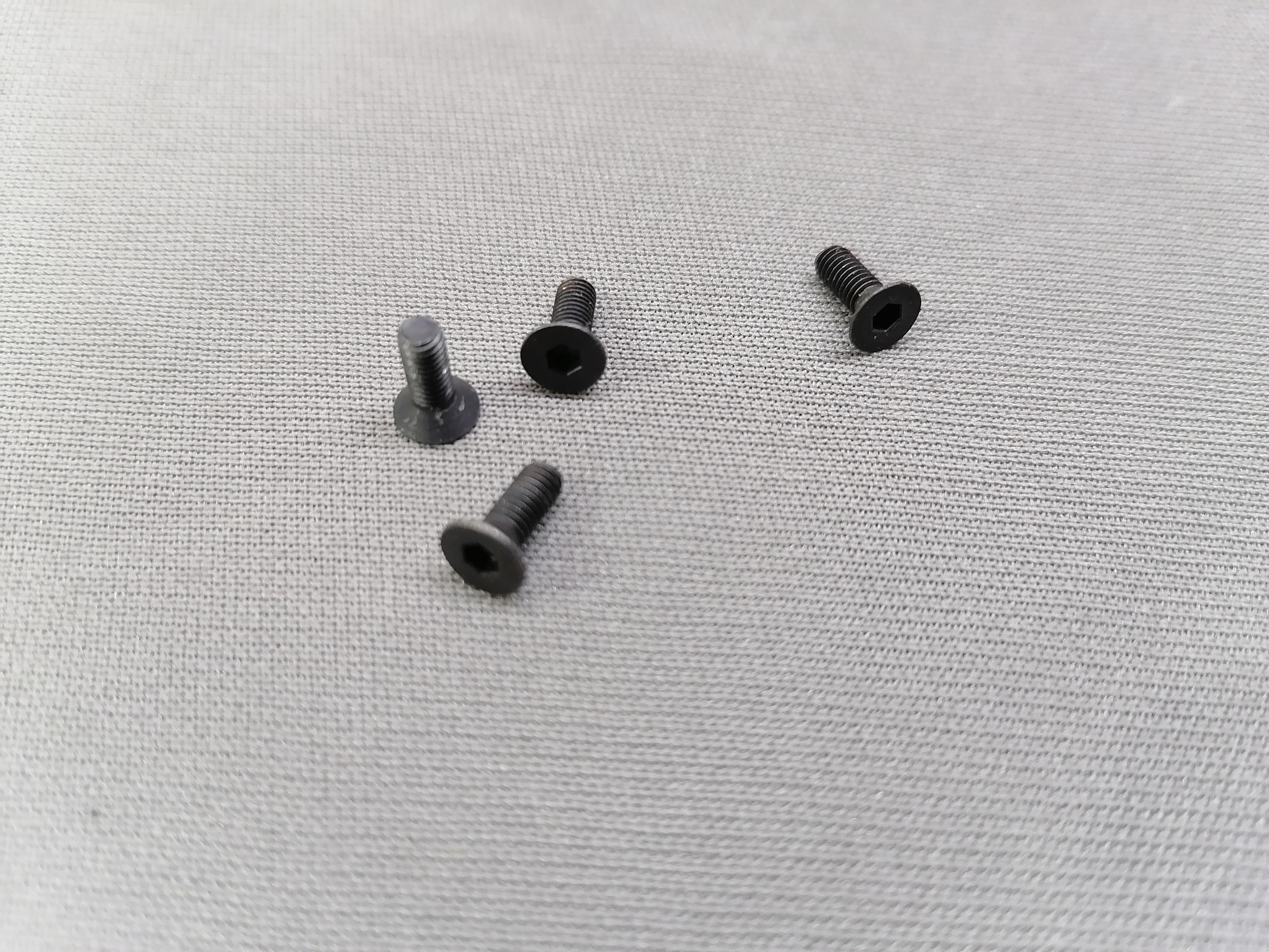
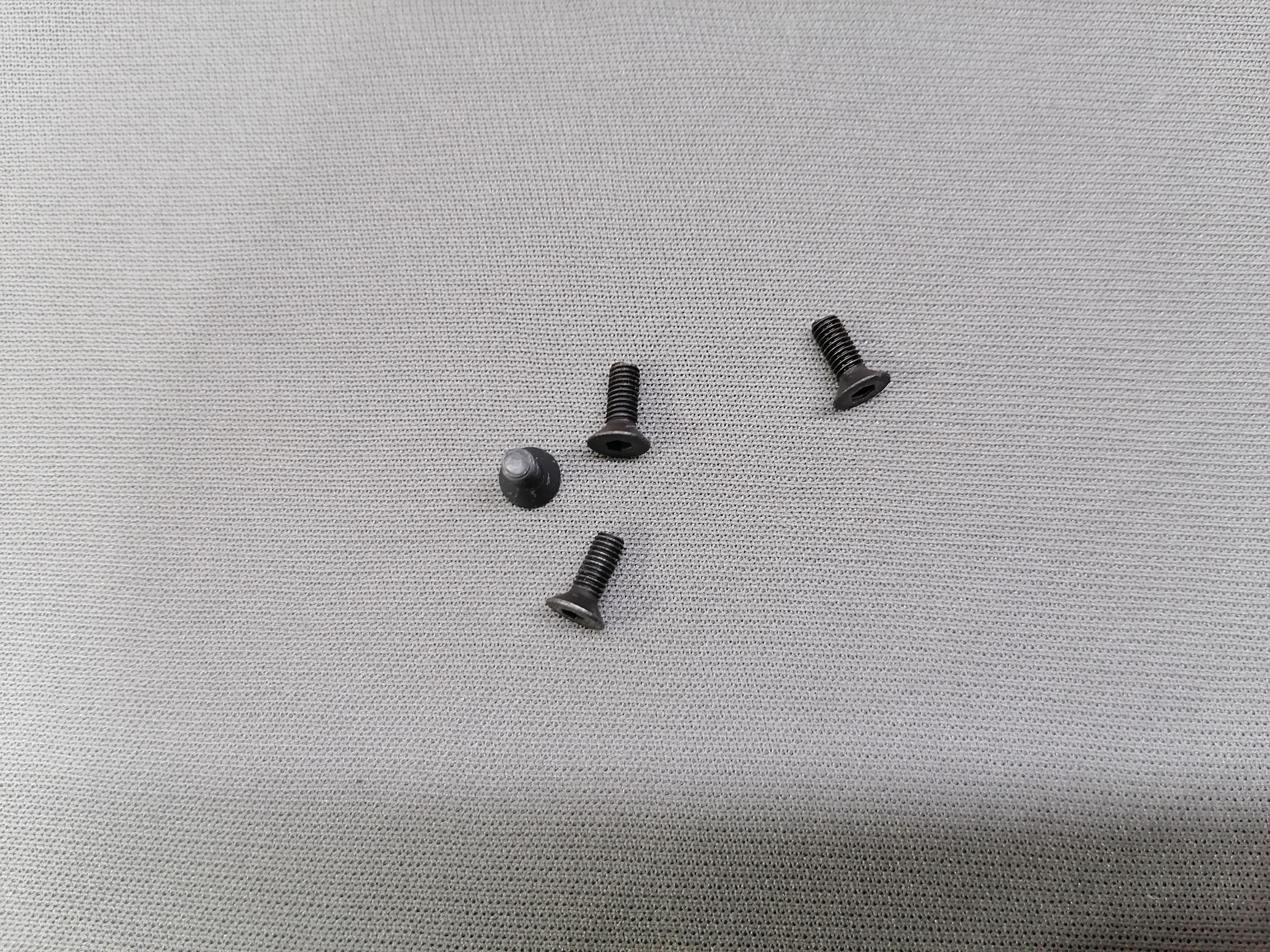
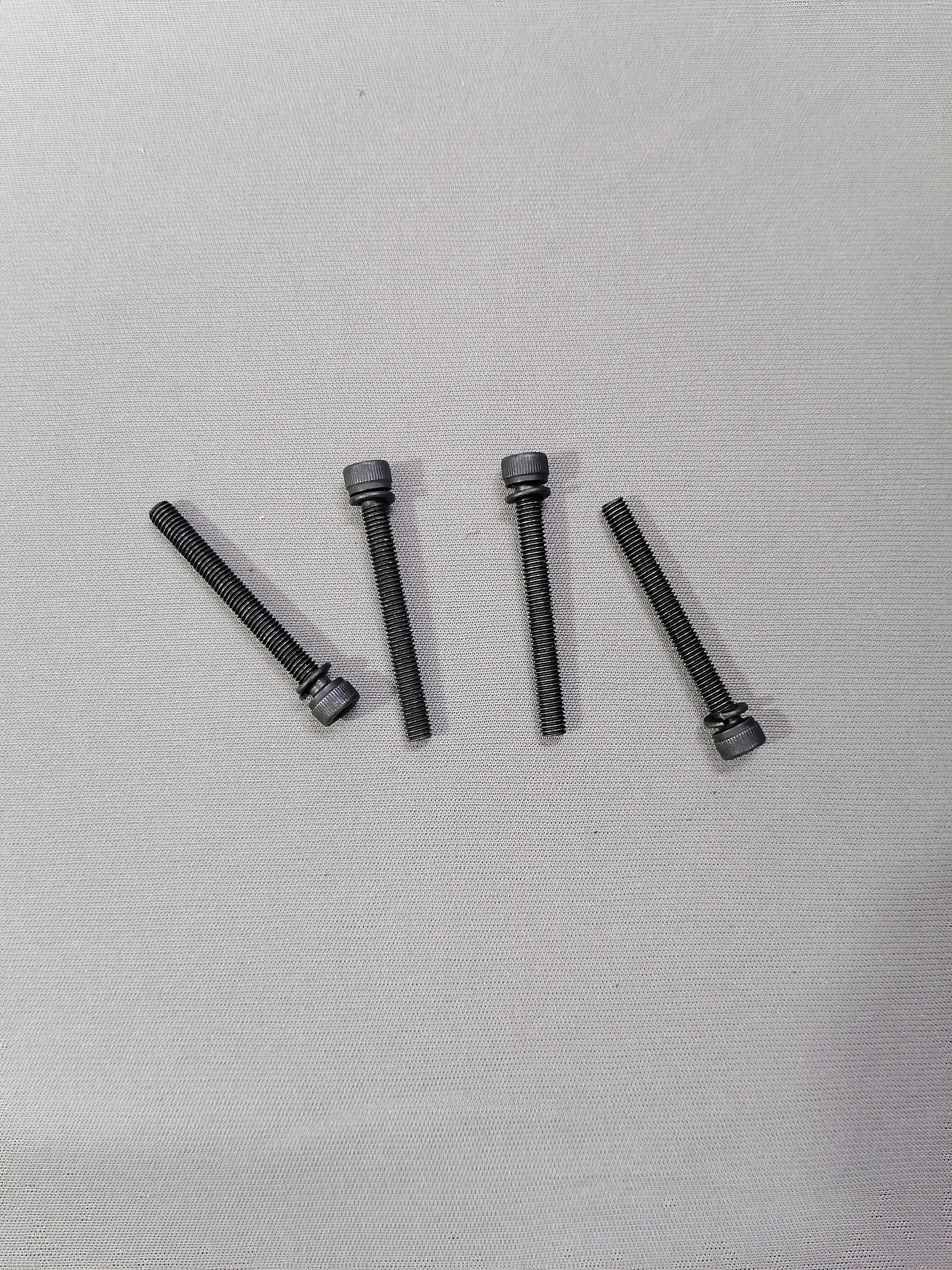
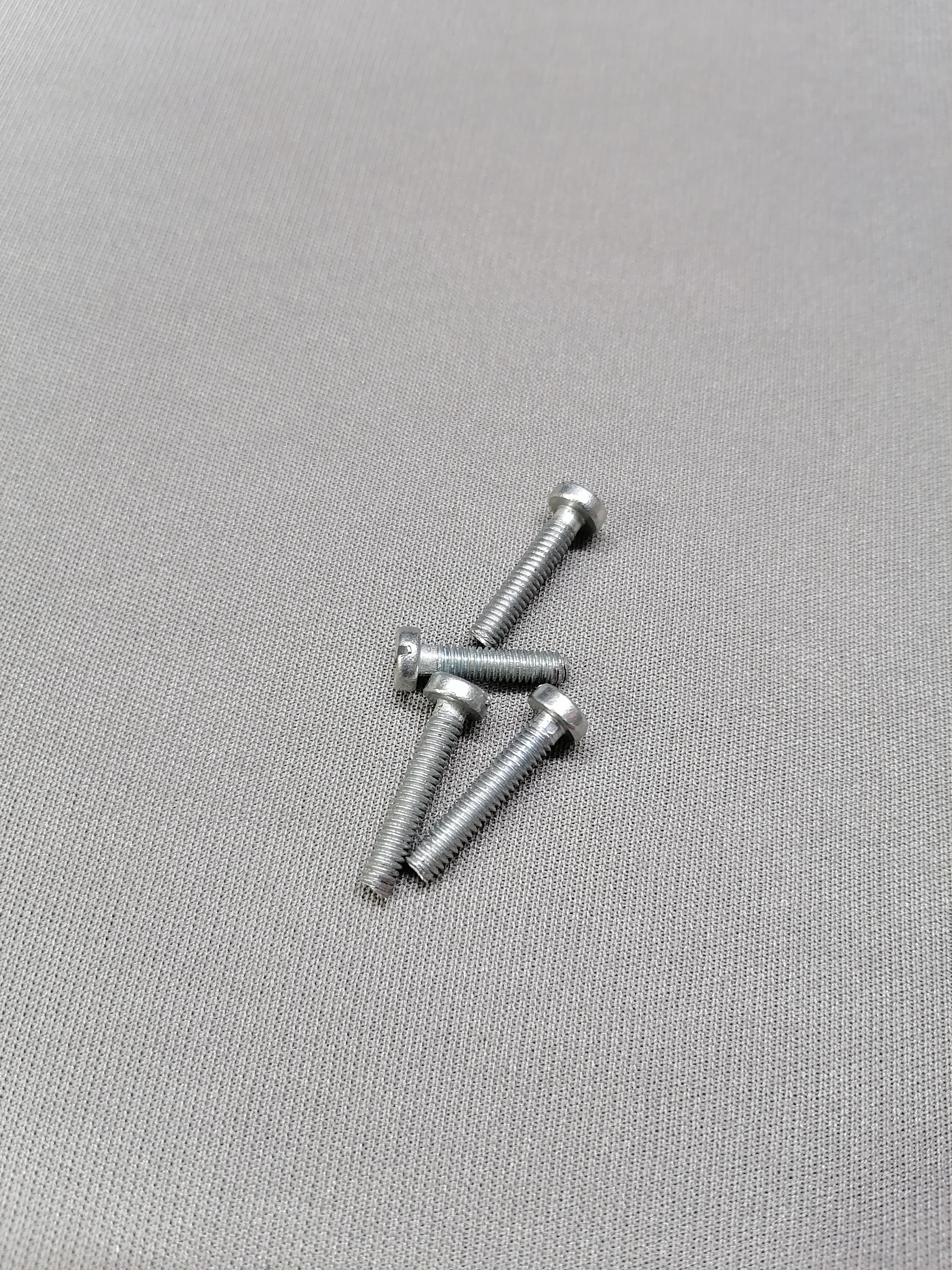
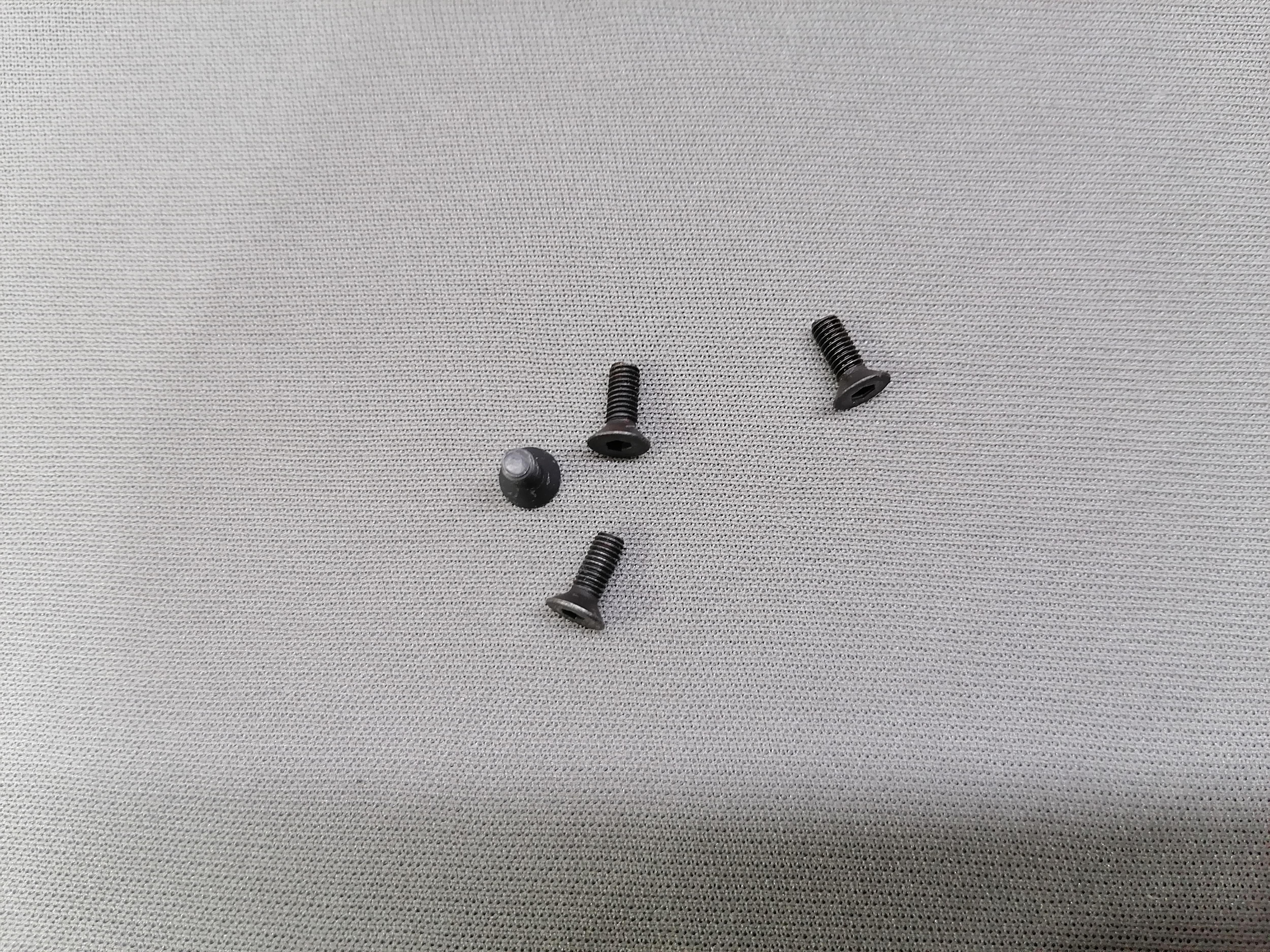
Use Allen Bolt( Bolt Head Cap) (5x60mm-4) and its nuts to attach the Base with CPU Bottom.
Note: Refer image for more understanding.
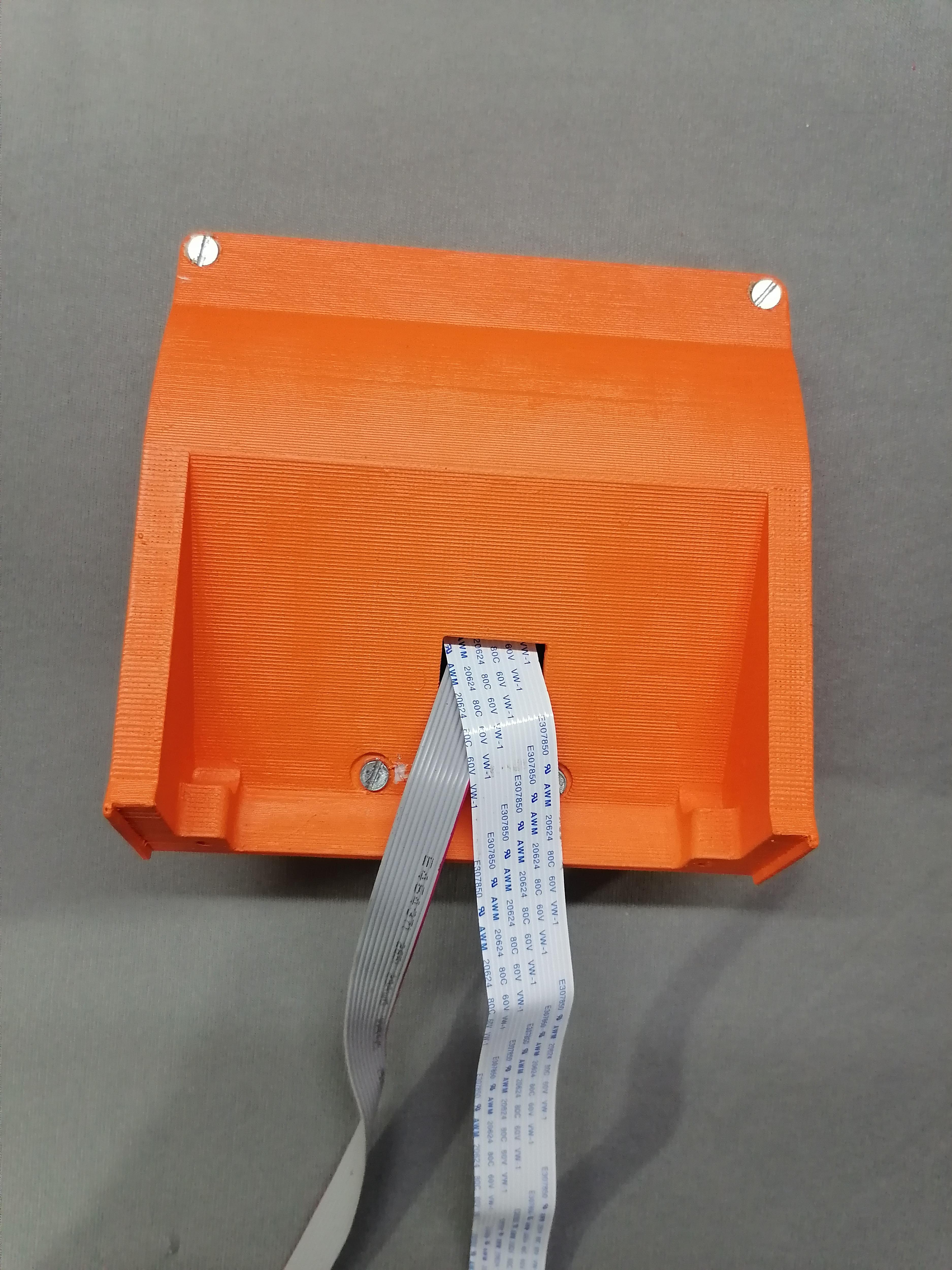
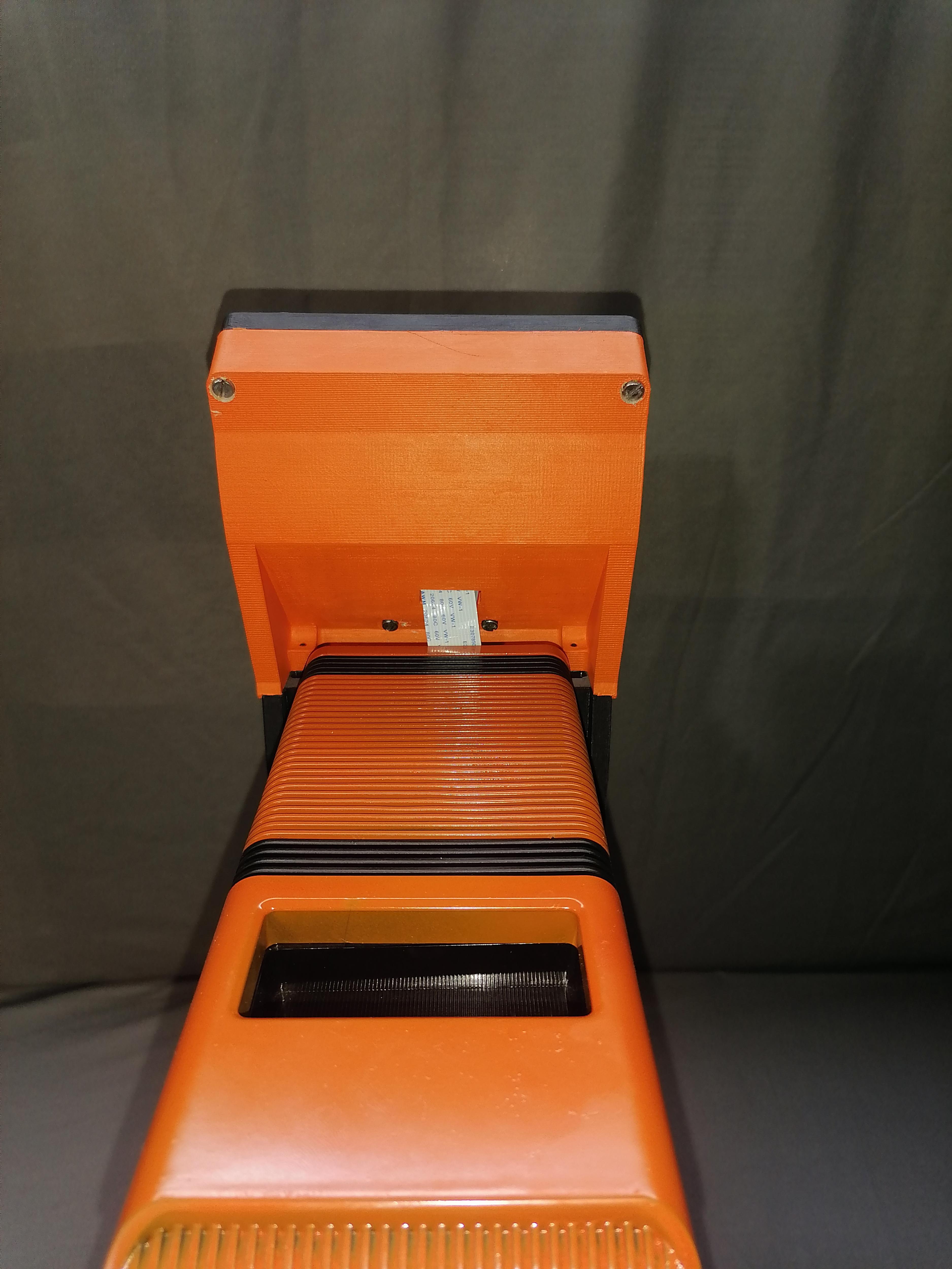
Insert the SD Card Extension Cable to Back Case LCD
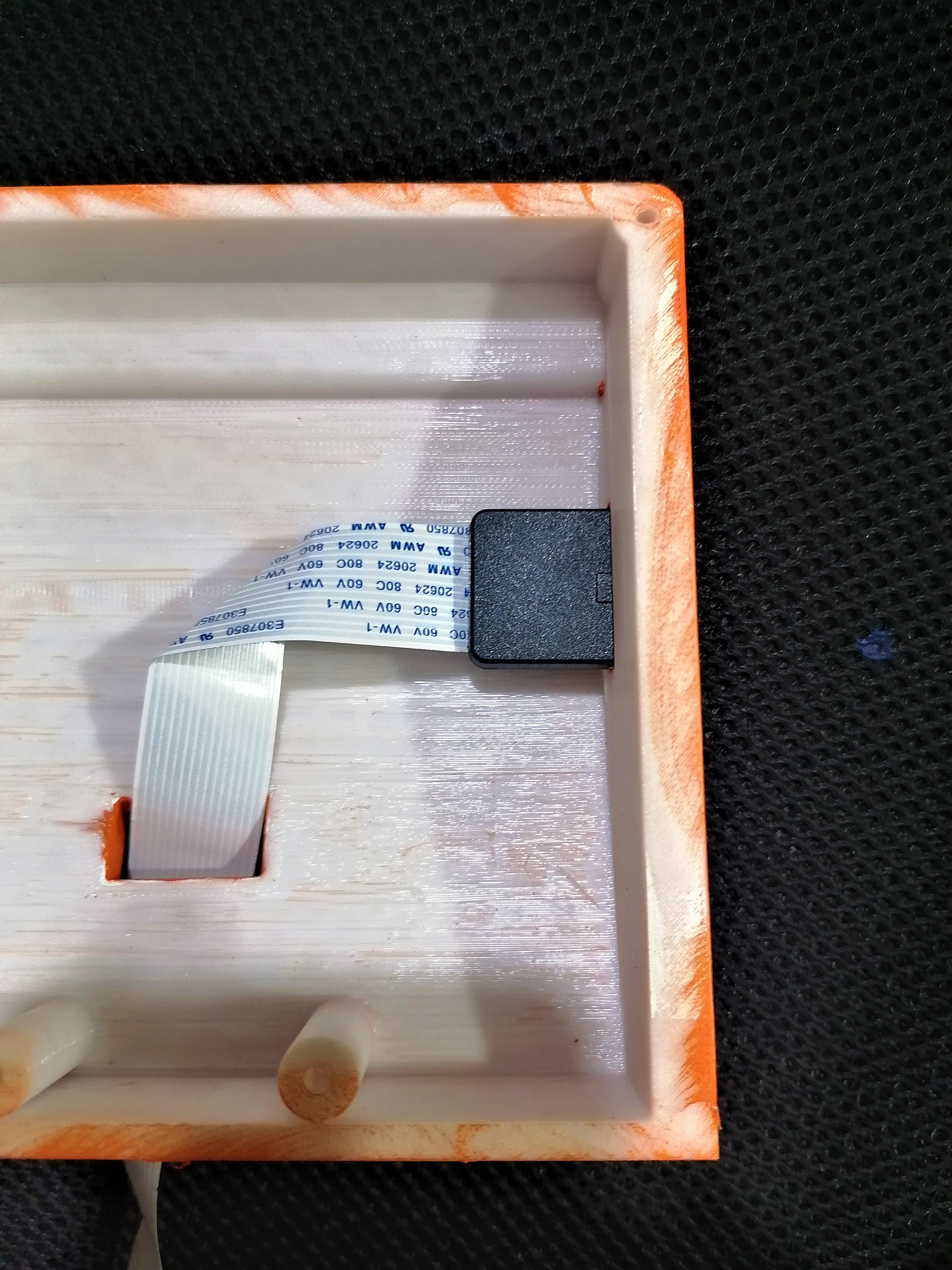
After inserting the SD Card Cable use super glue to glue permanent.
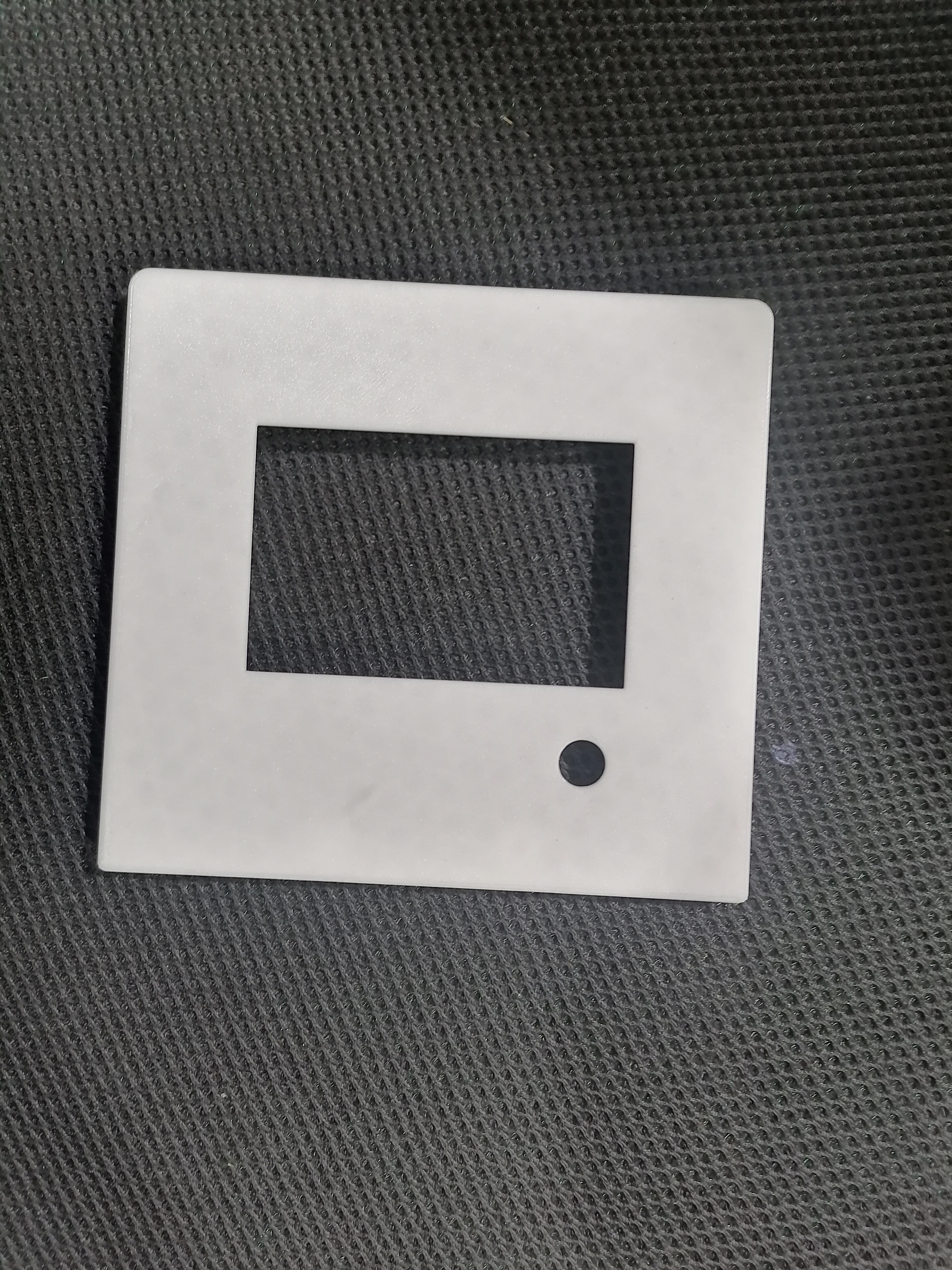
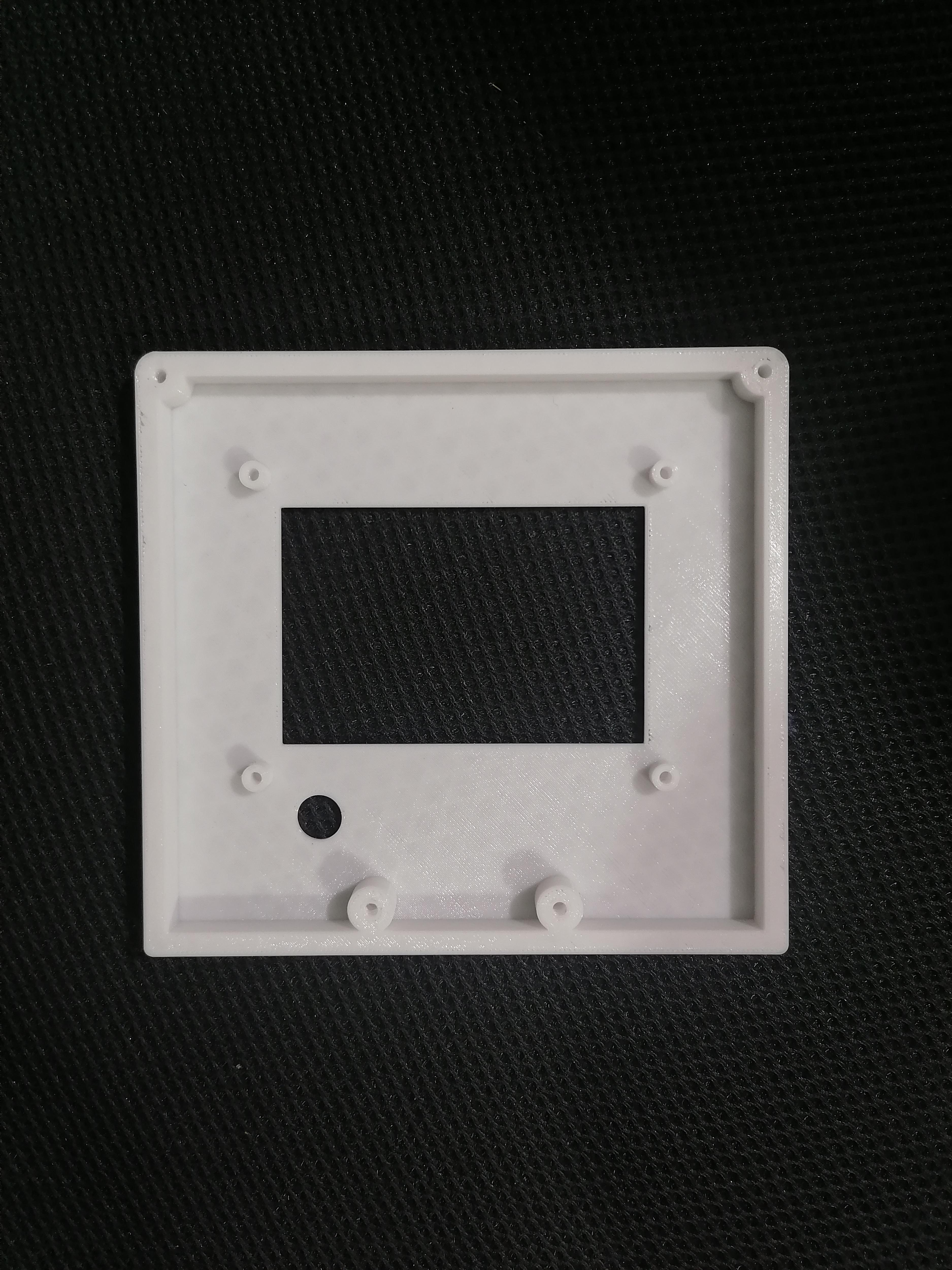
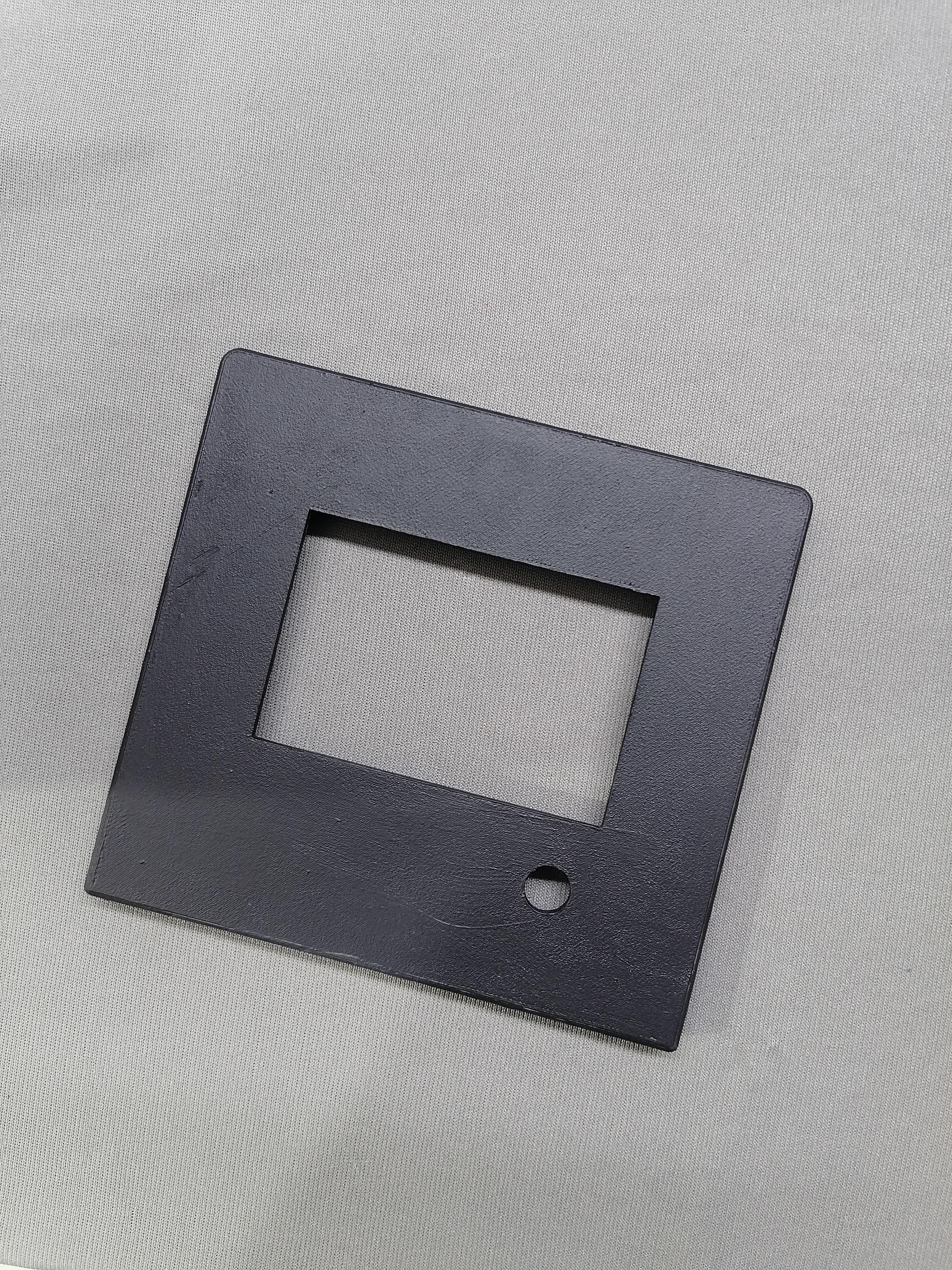
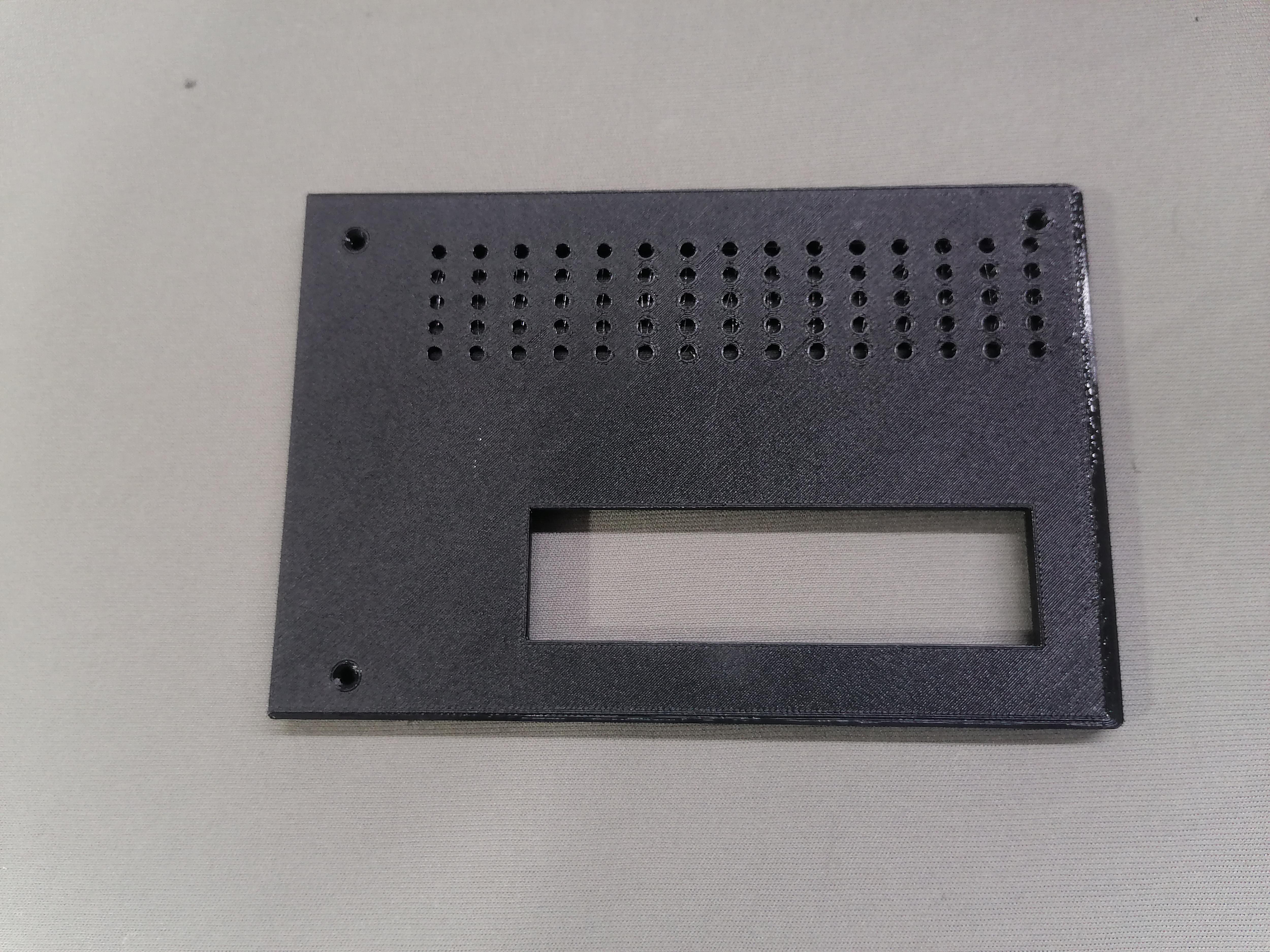
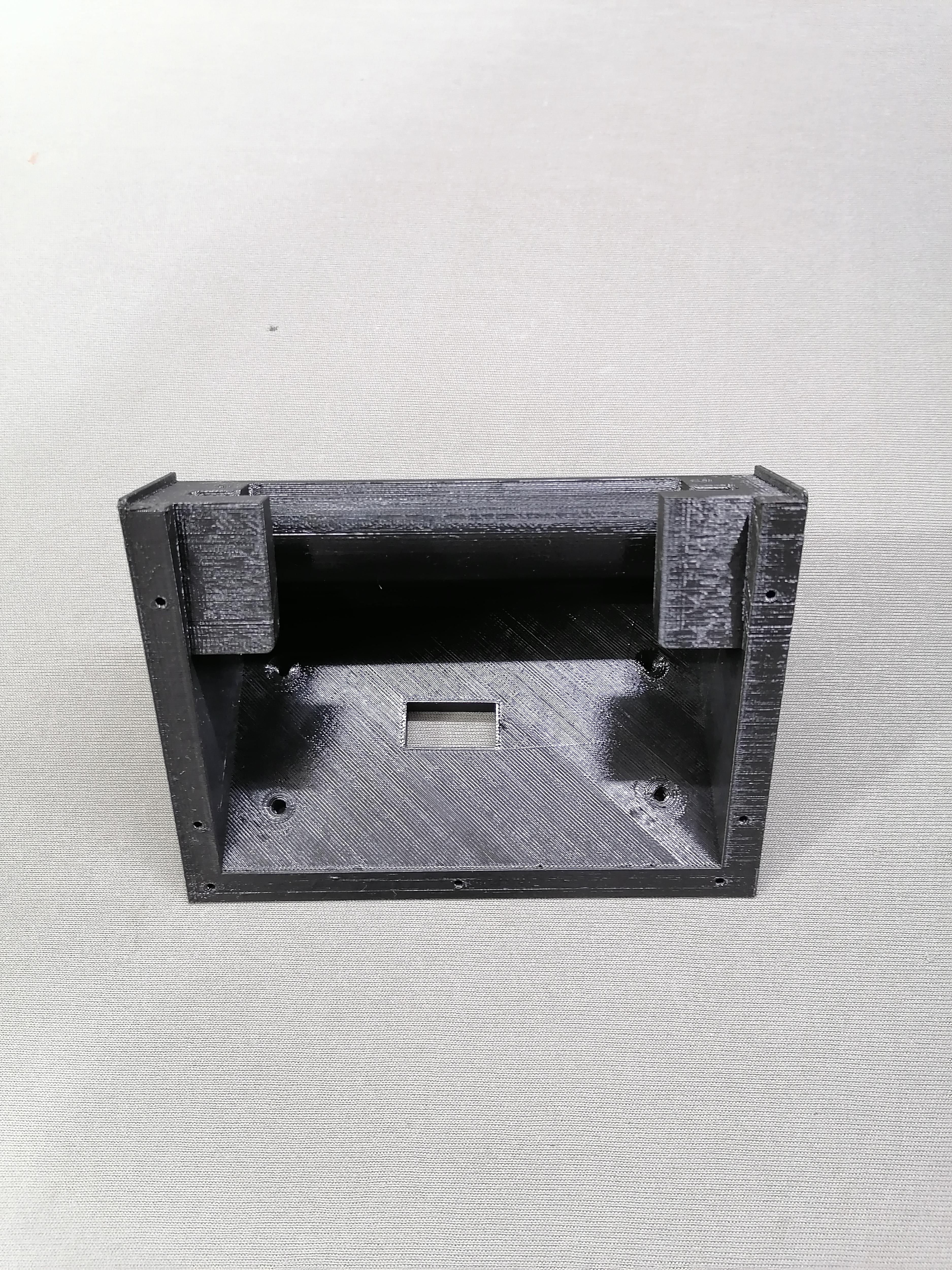
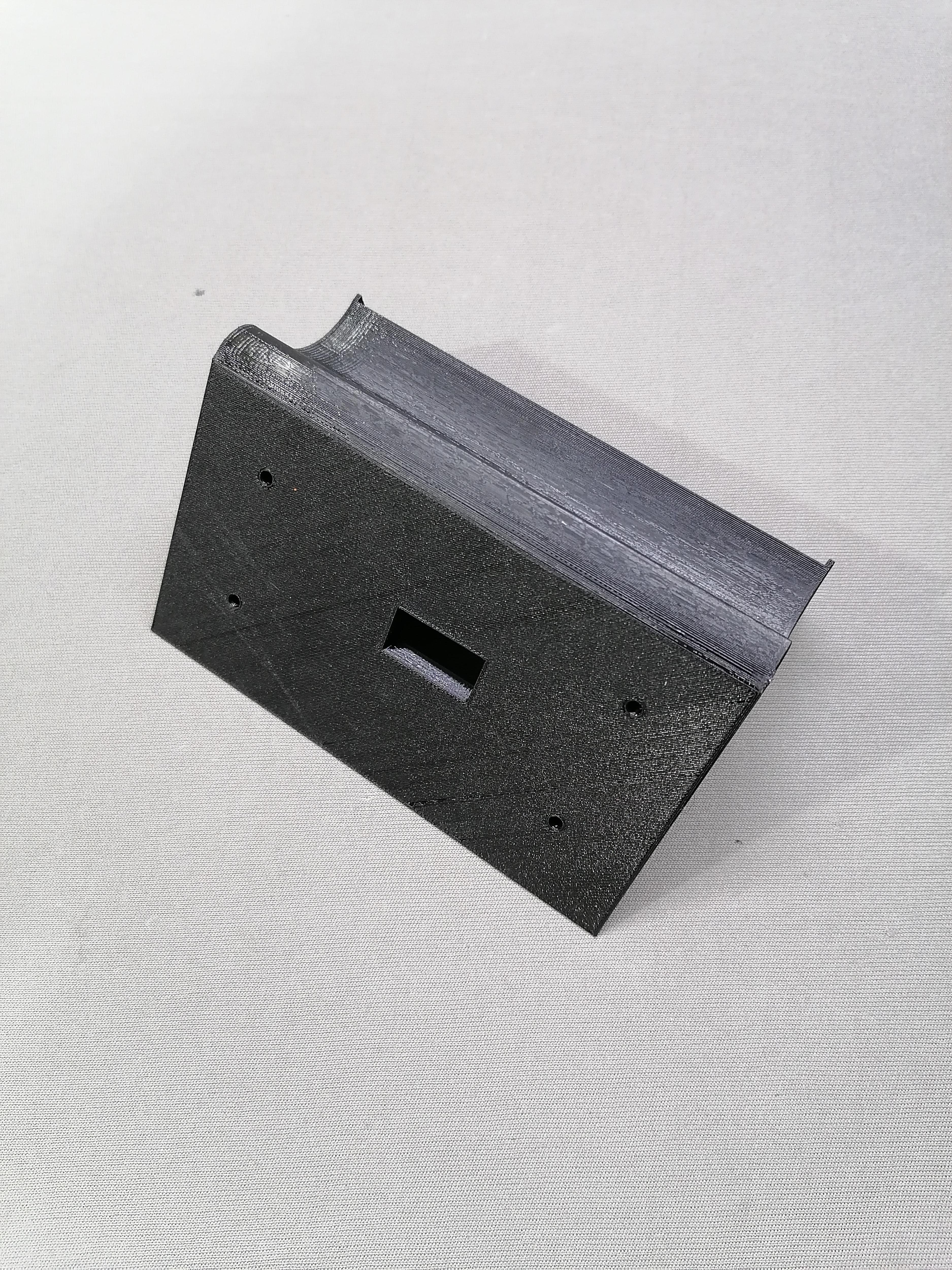
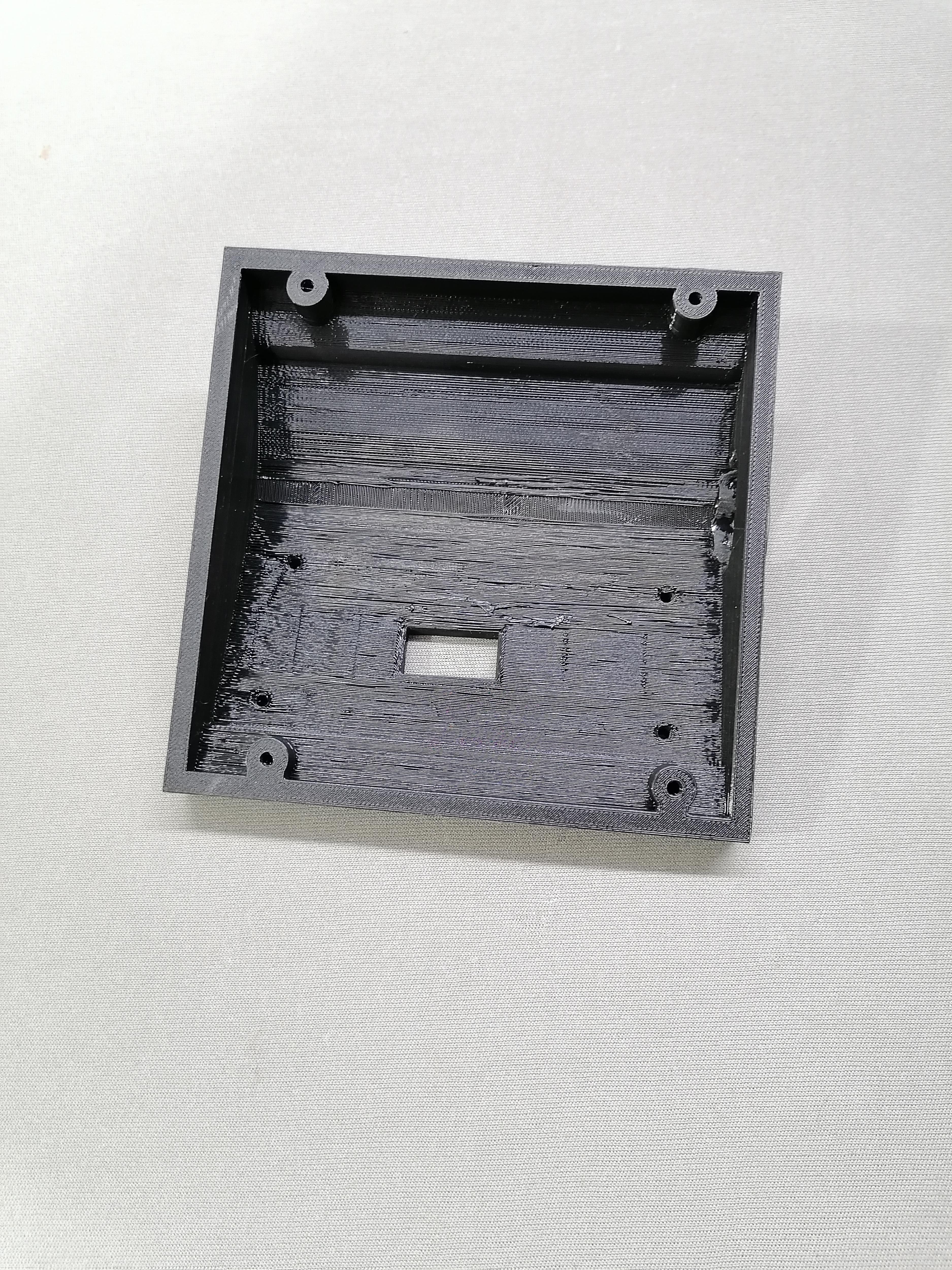
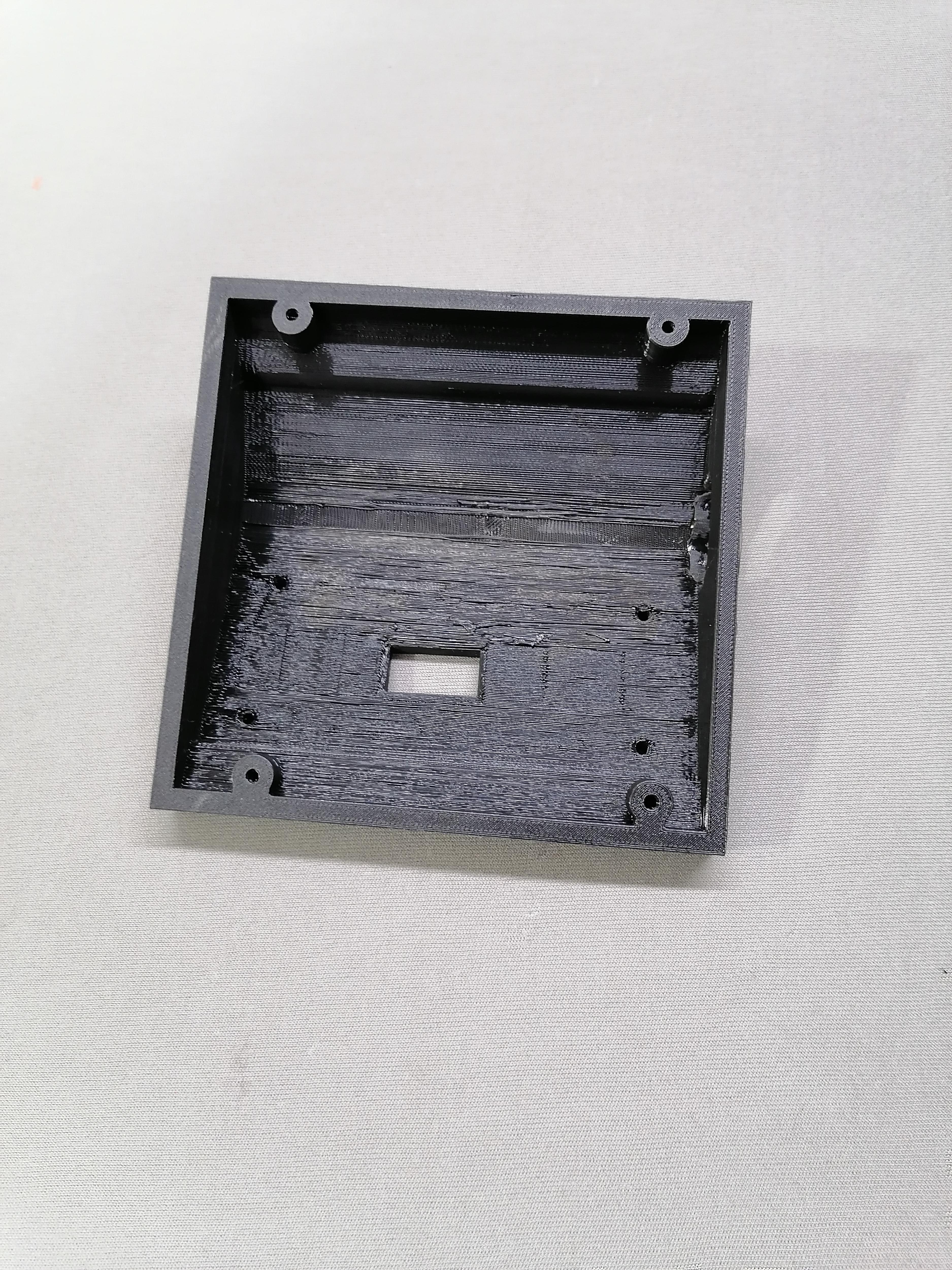
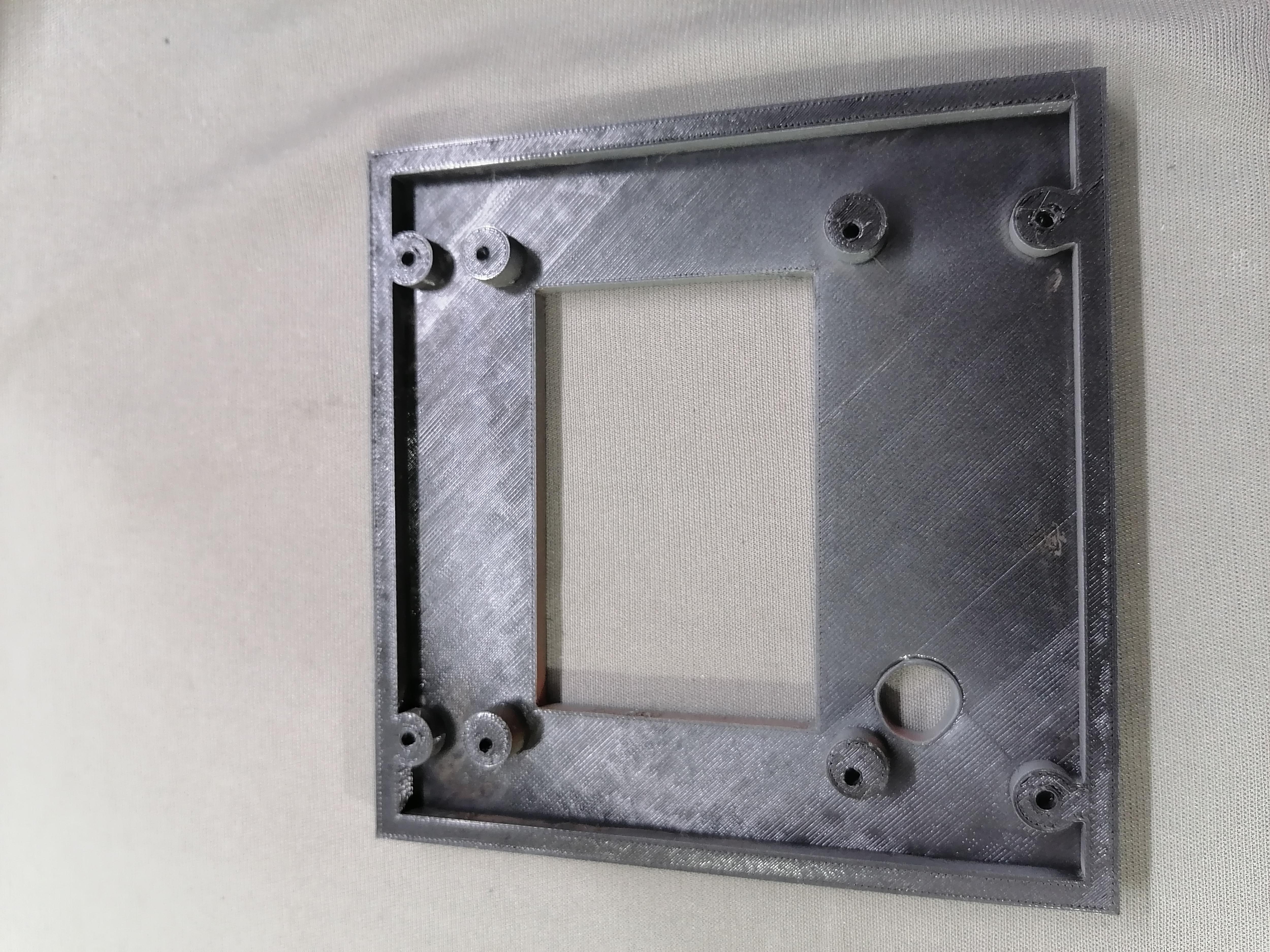
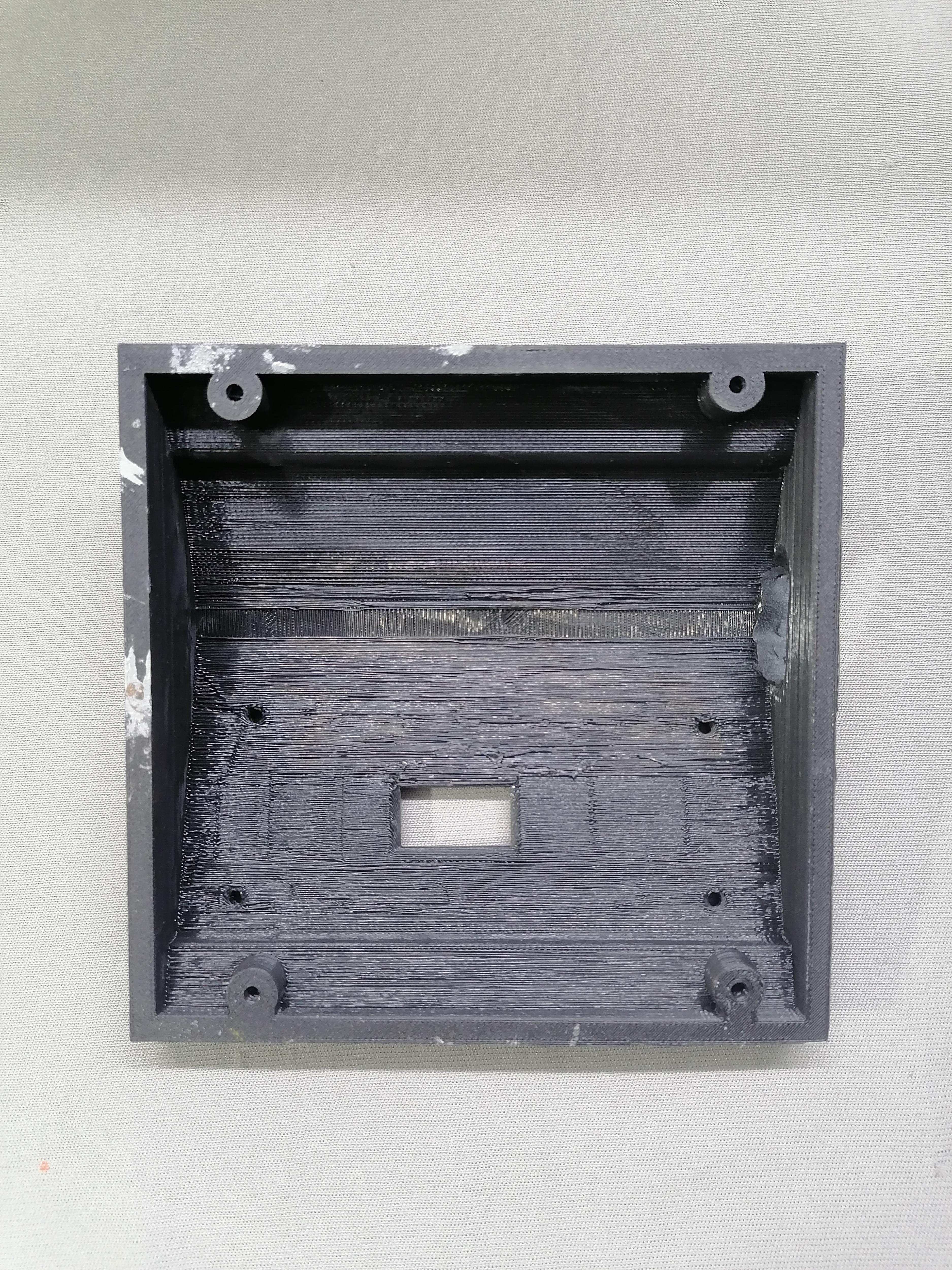
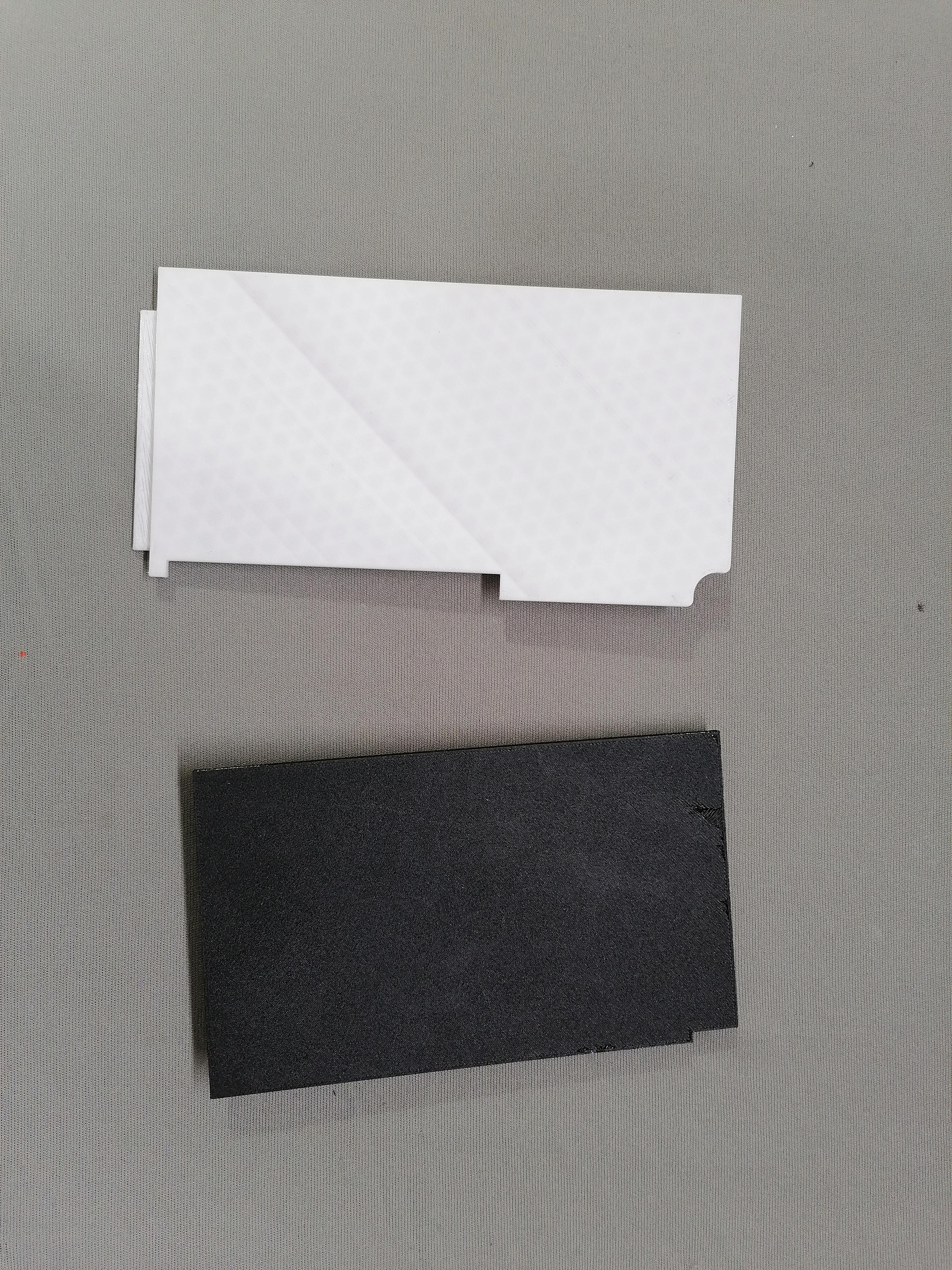
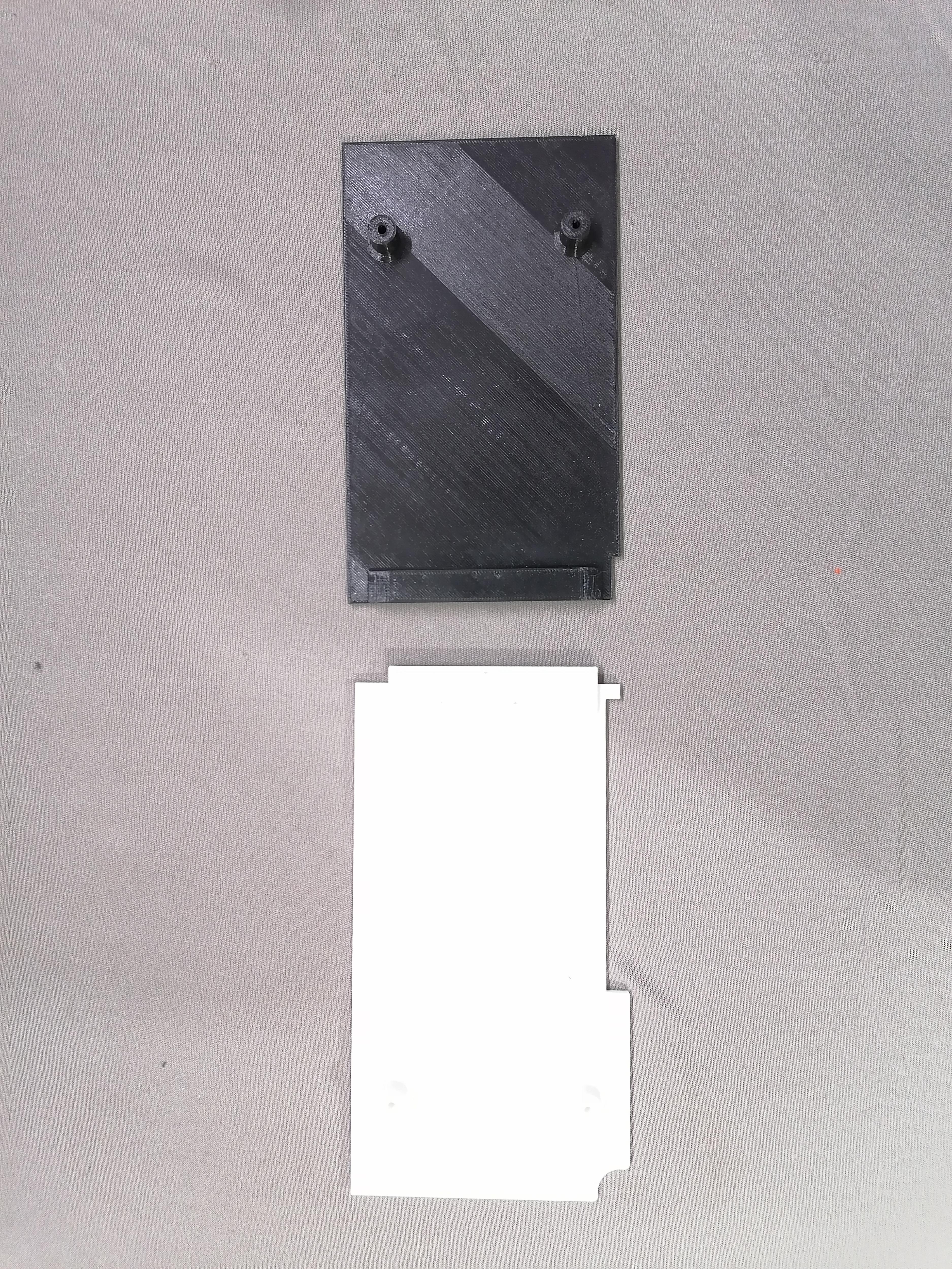
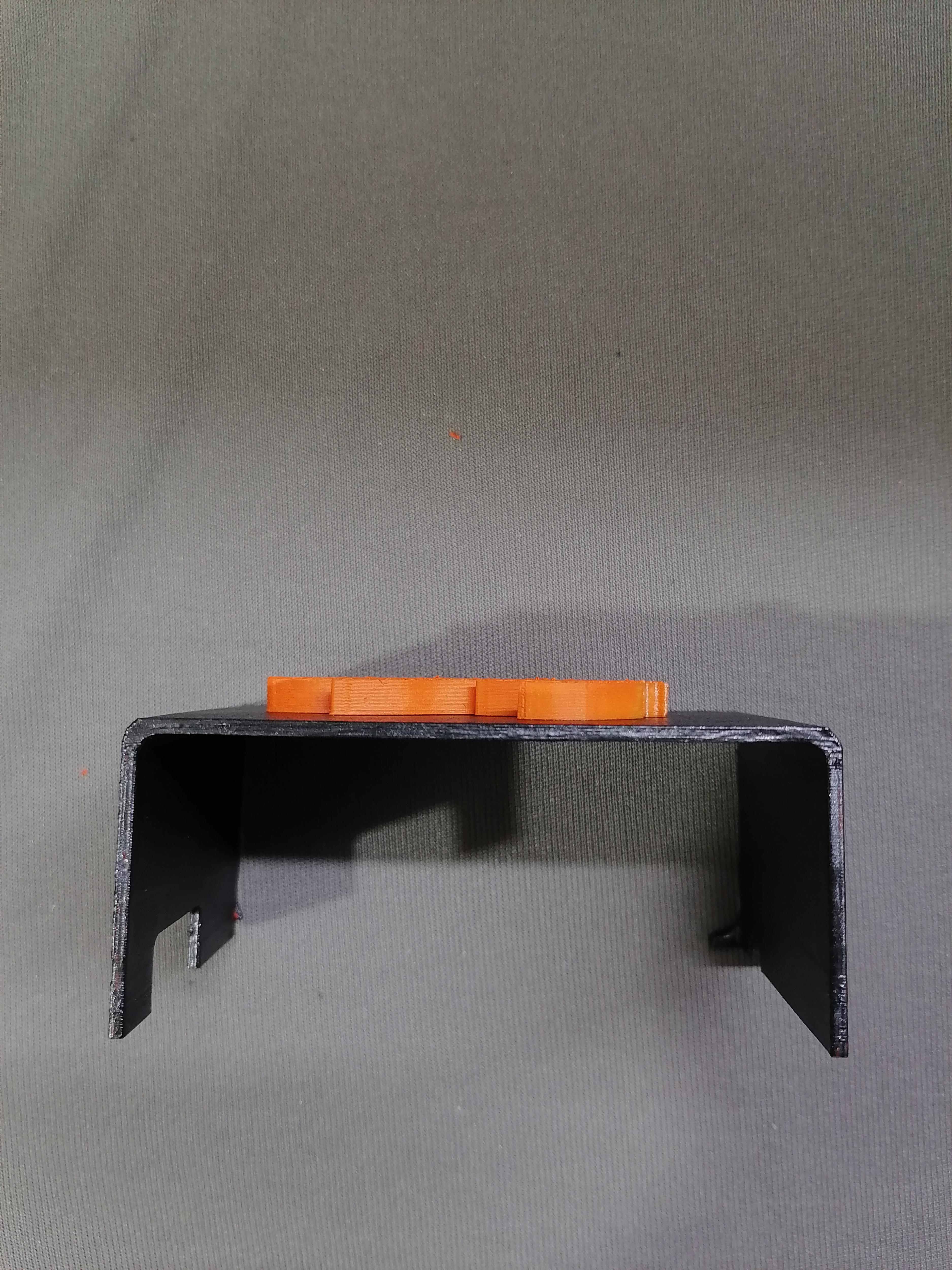
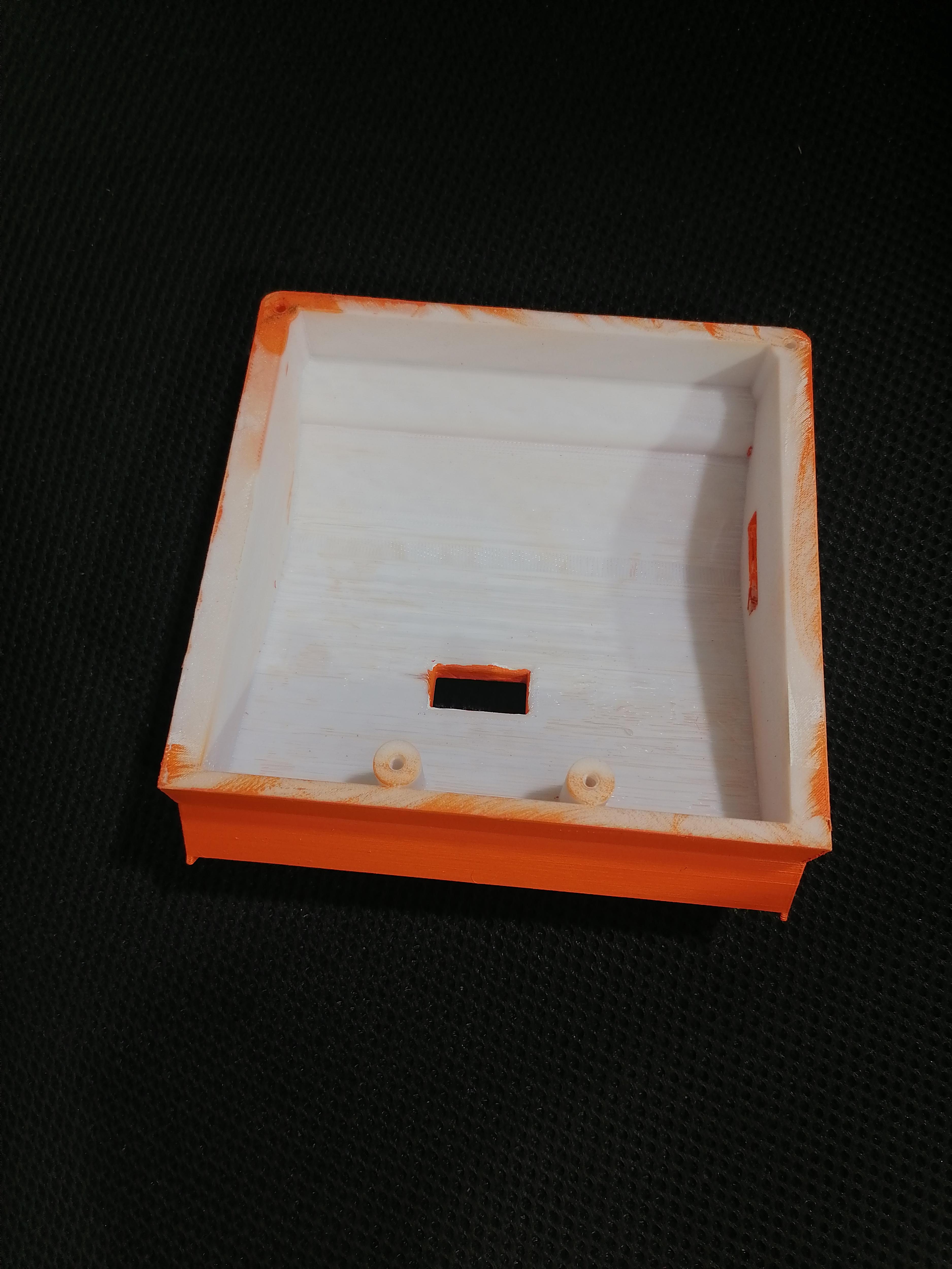
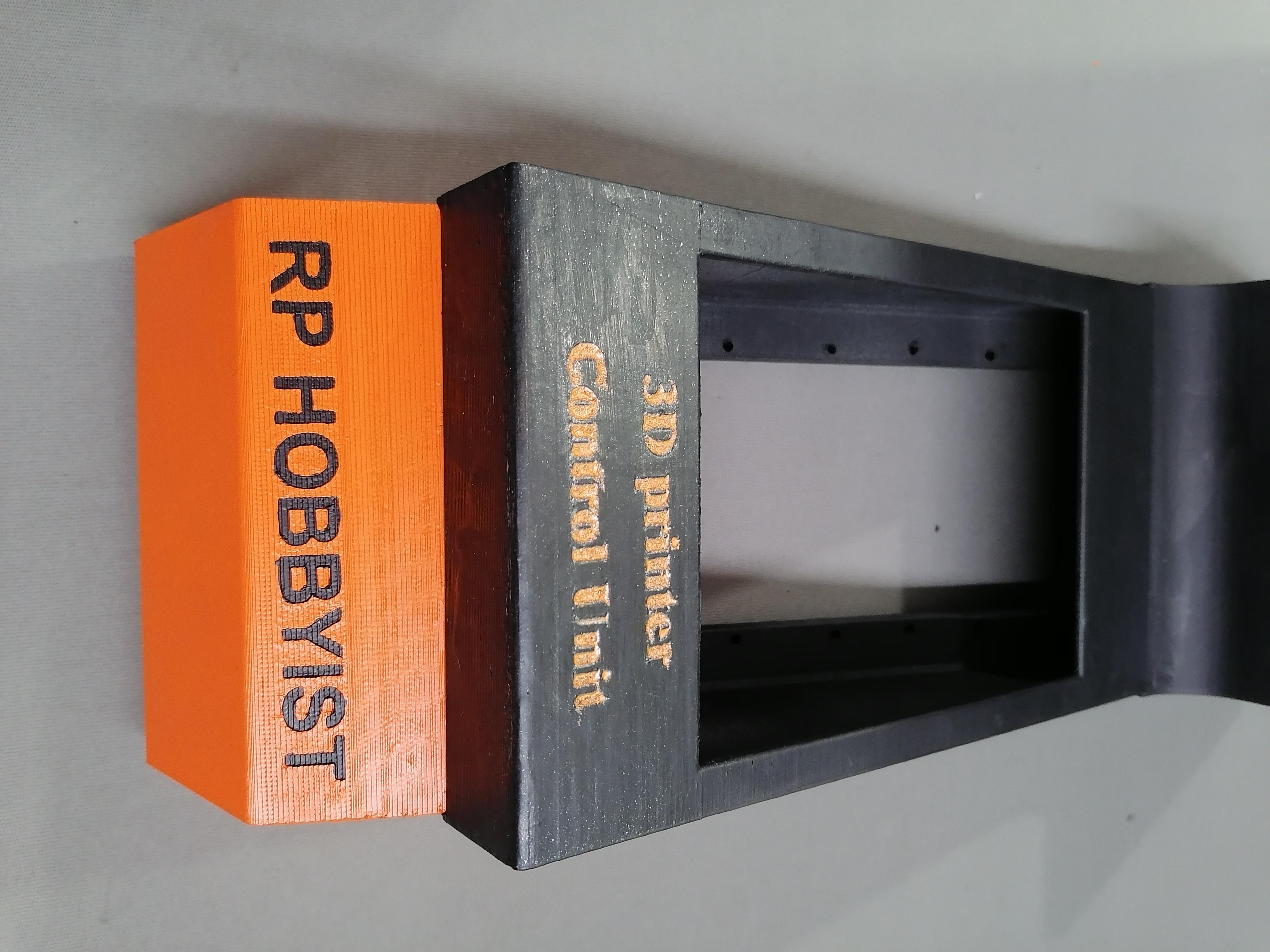
Assembling the LCD Body
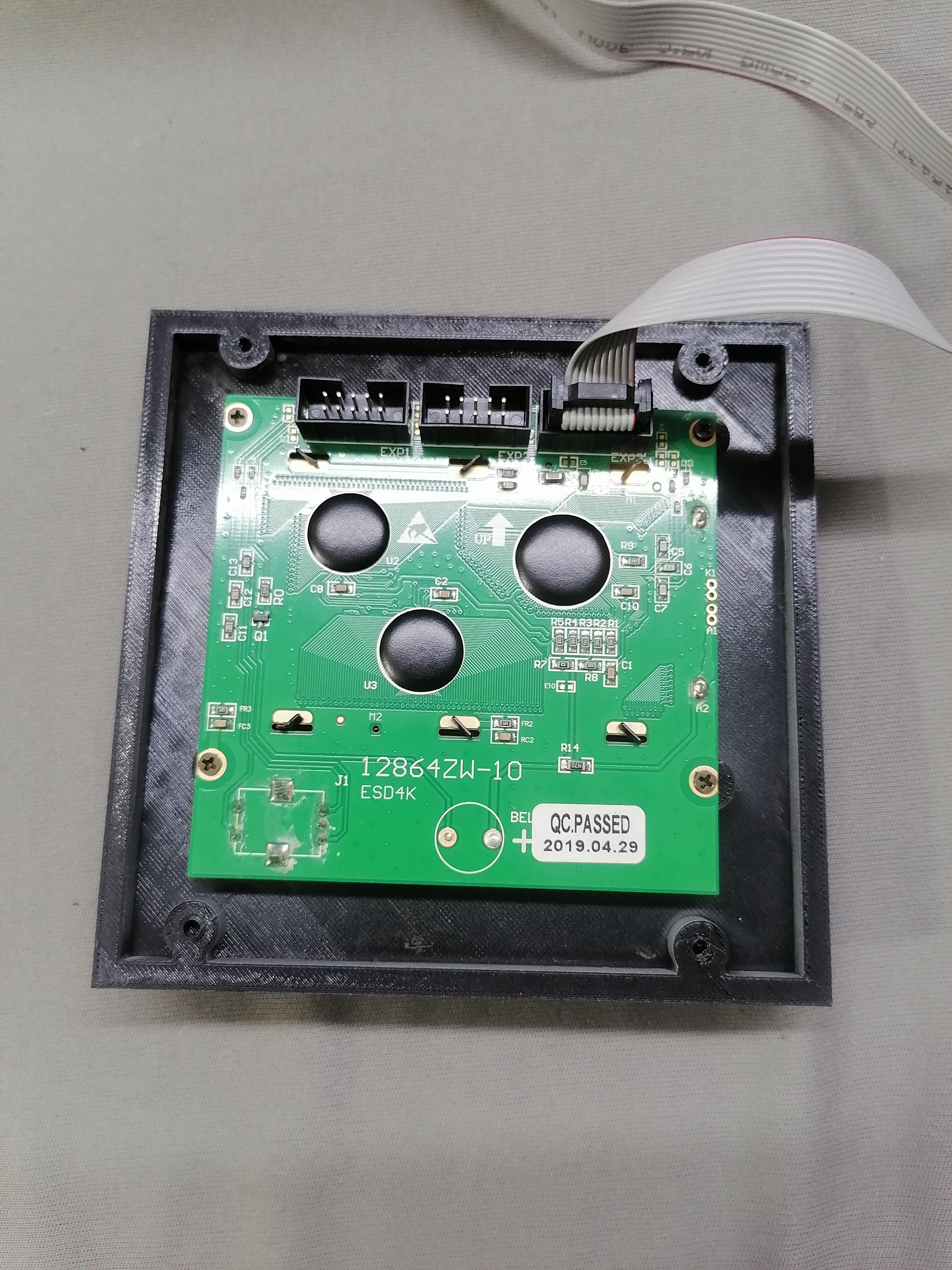
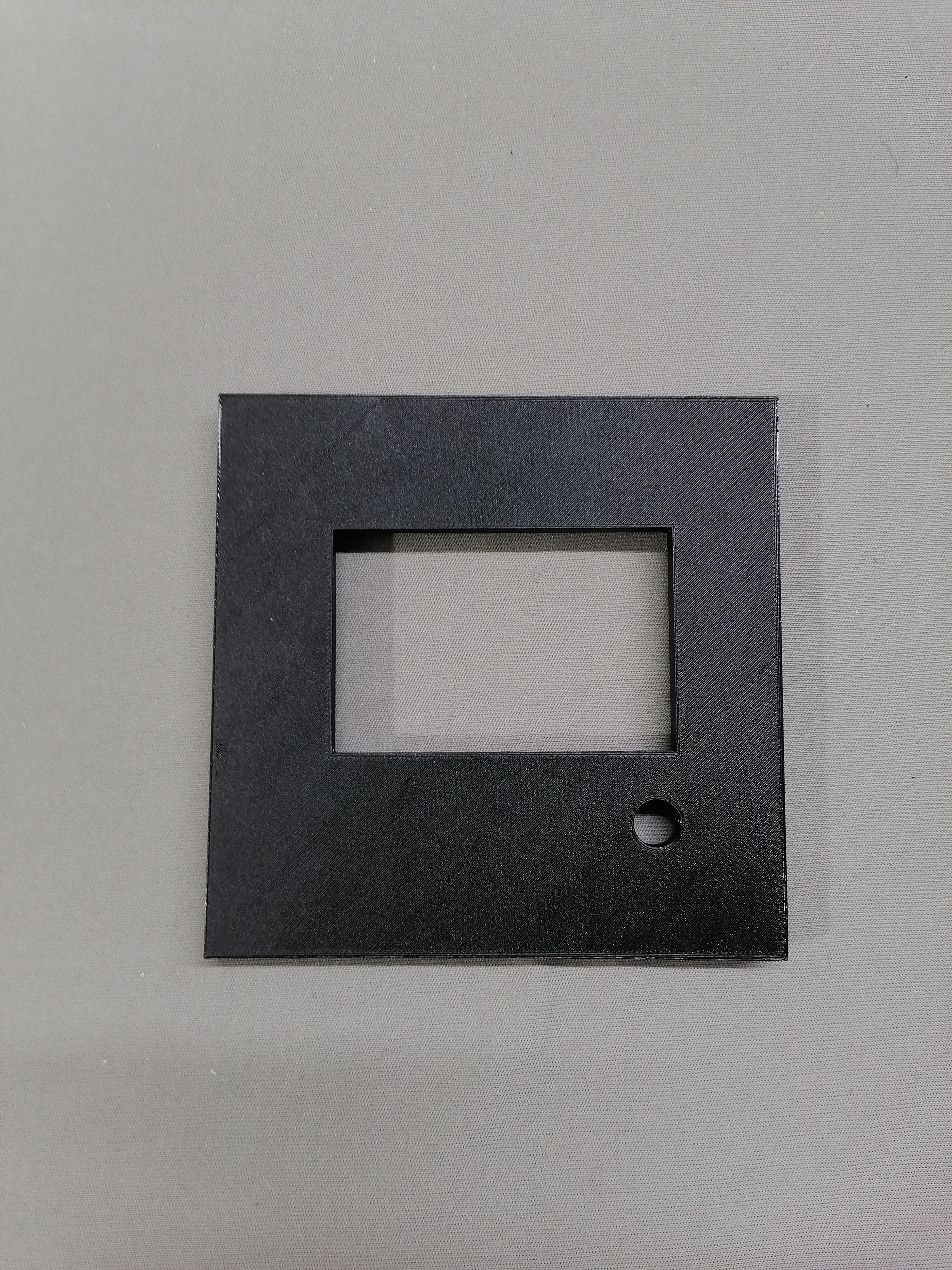
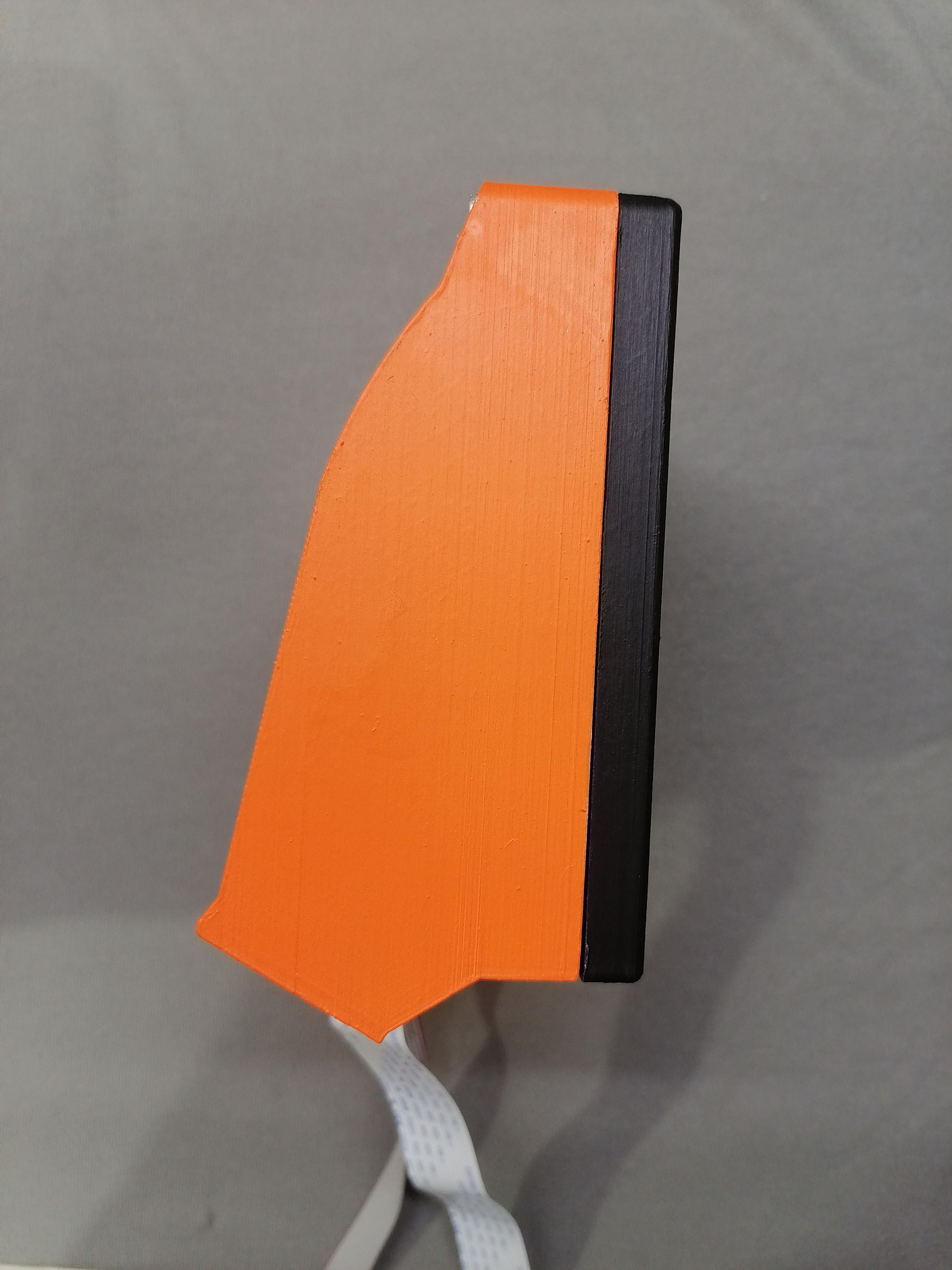

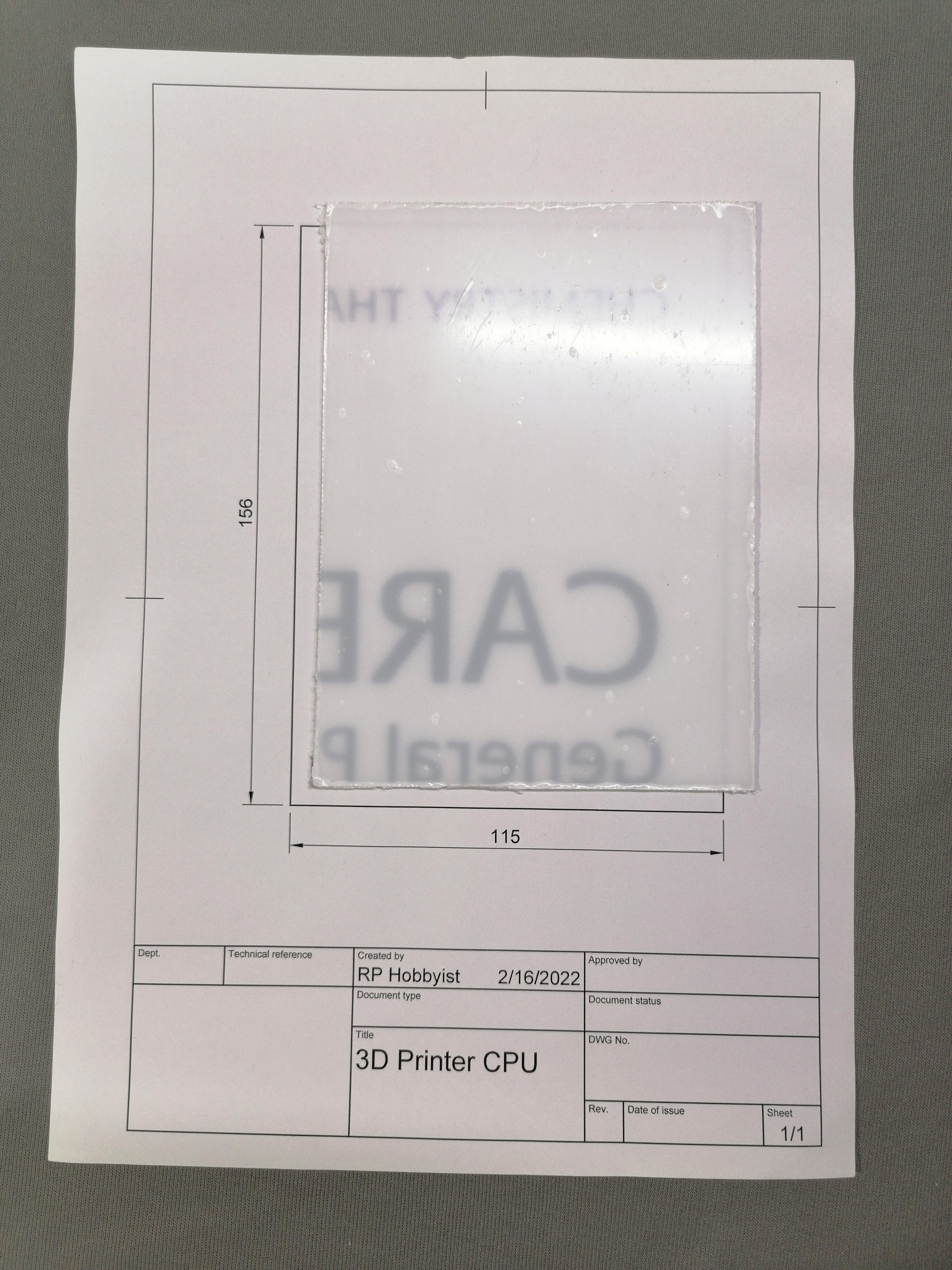
Attach the LCD with screw to its holder. Now put the acrylic sheet as per dimension of LCD screen.
Pass the cables from the given back hole and then after close Back lid with screw.
Note: Refer image for more understanding.
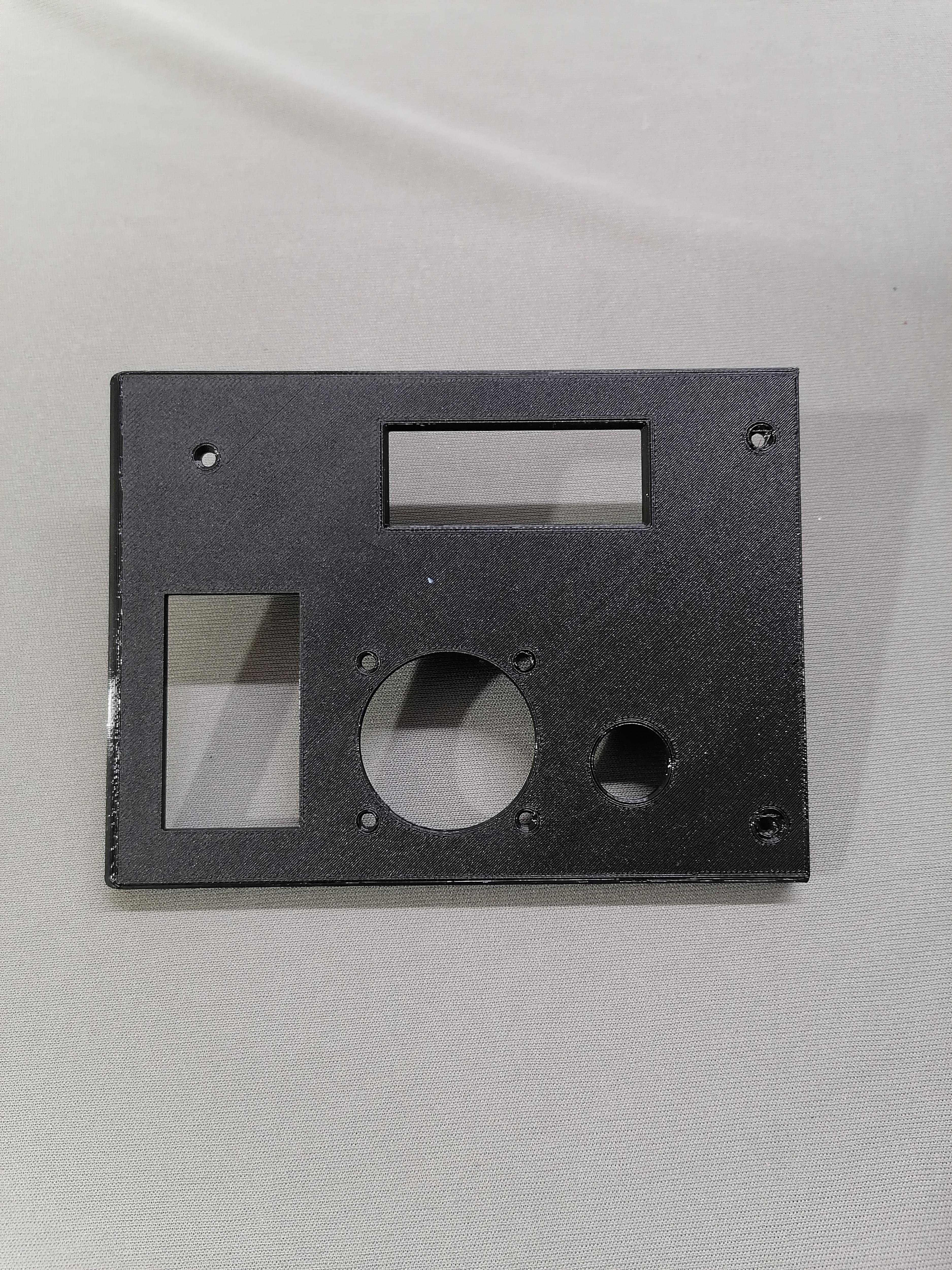
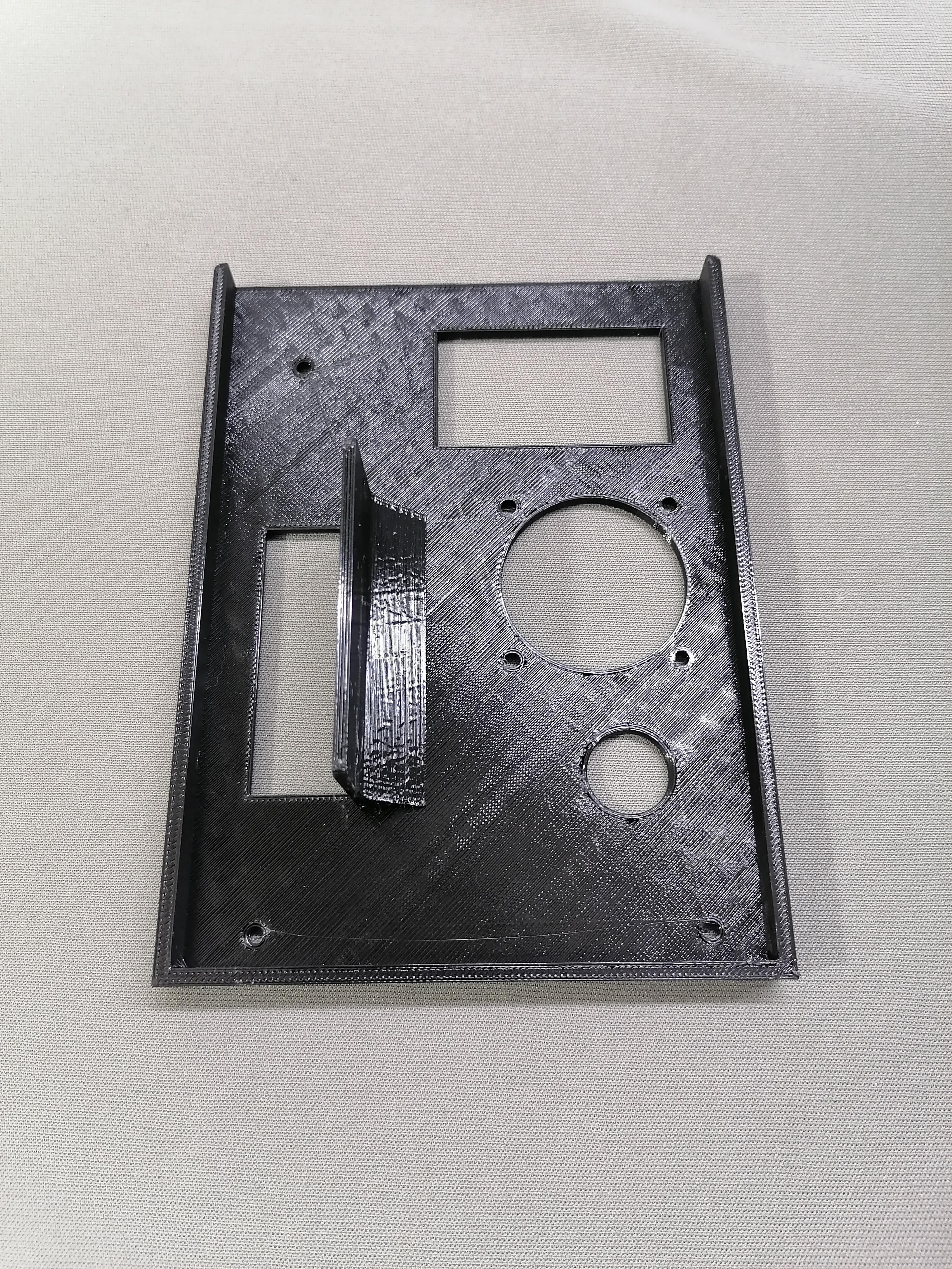
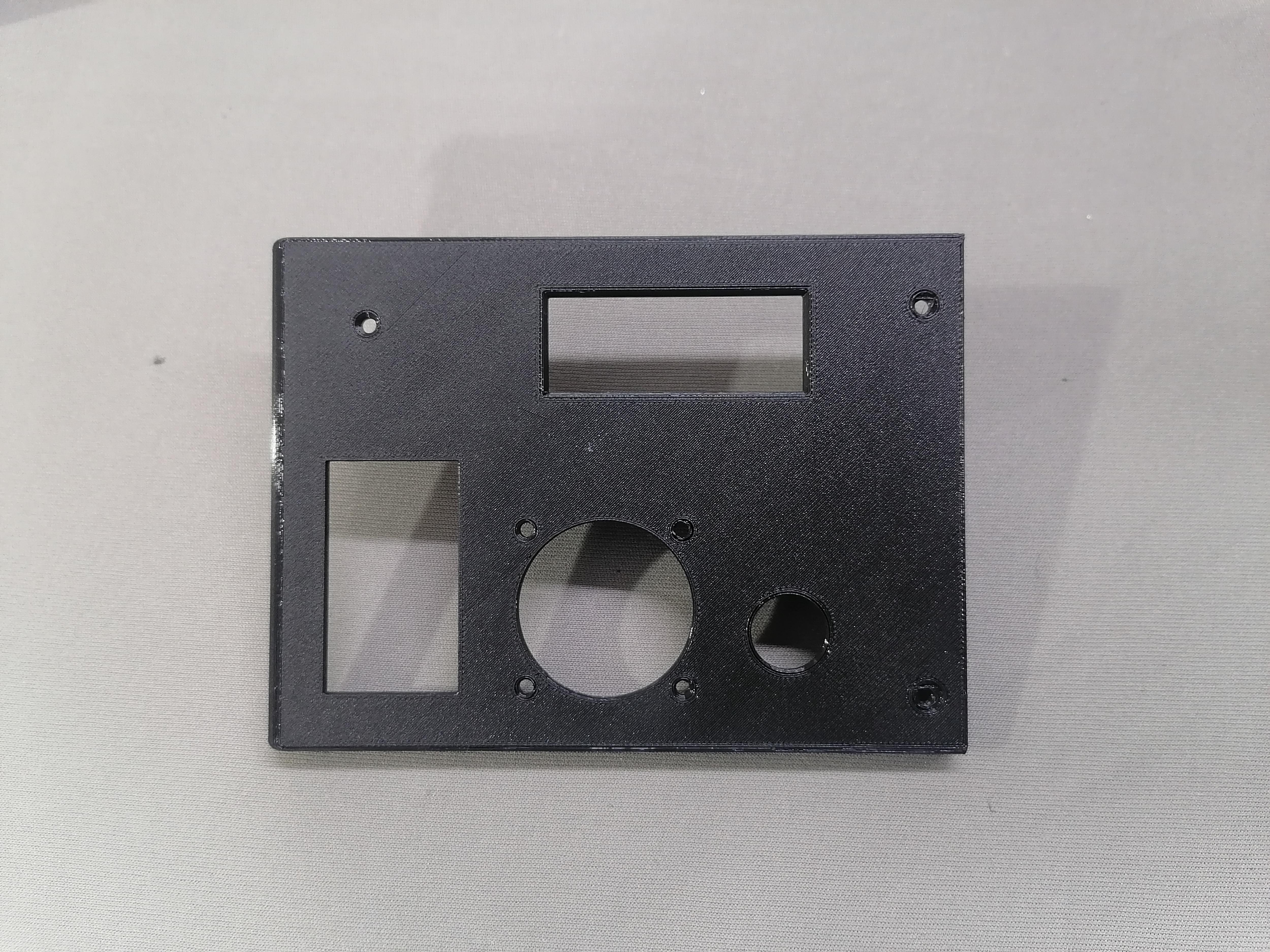
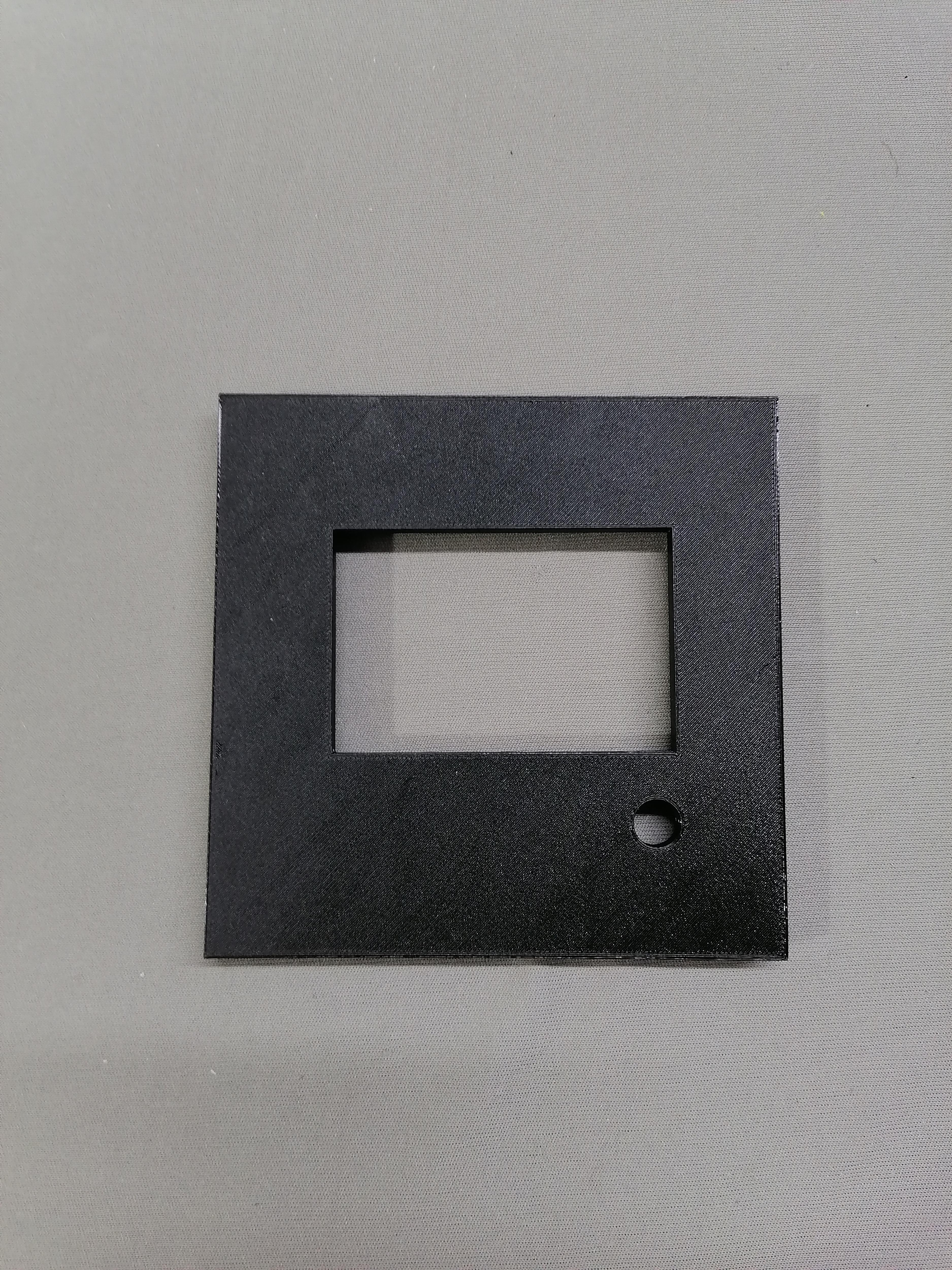
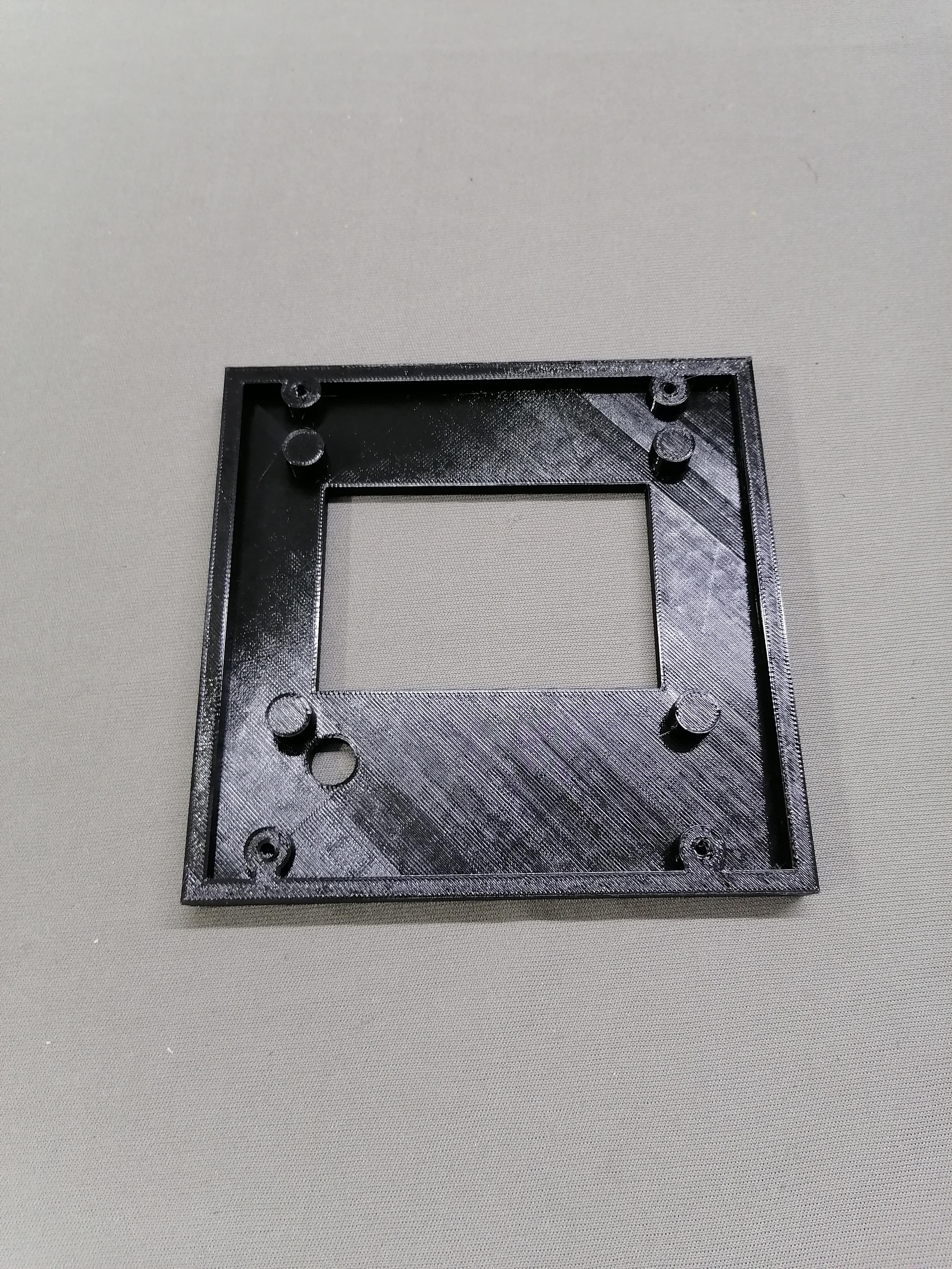
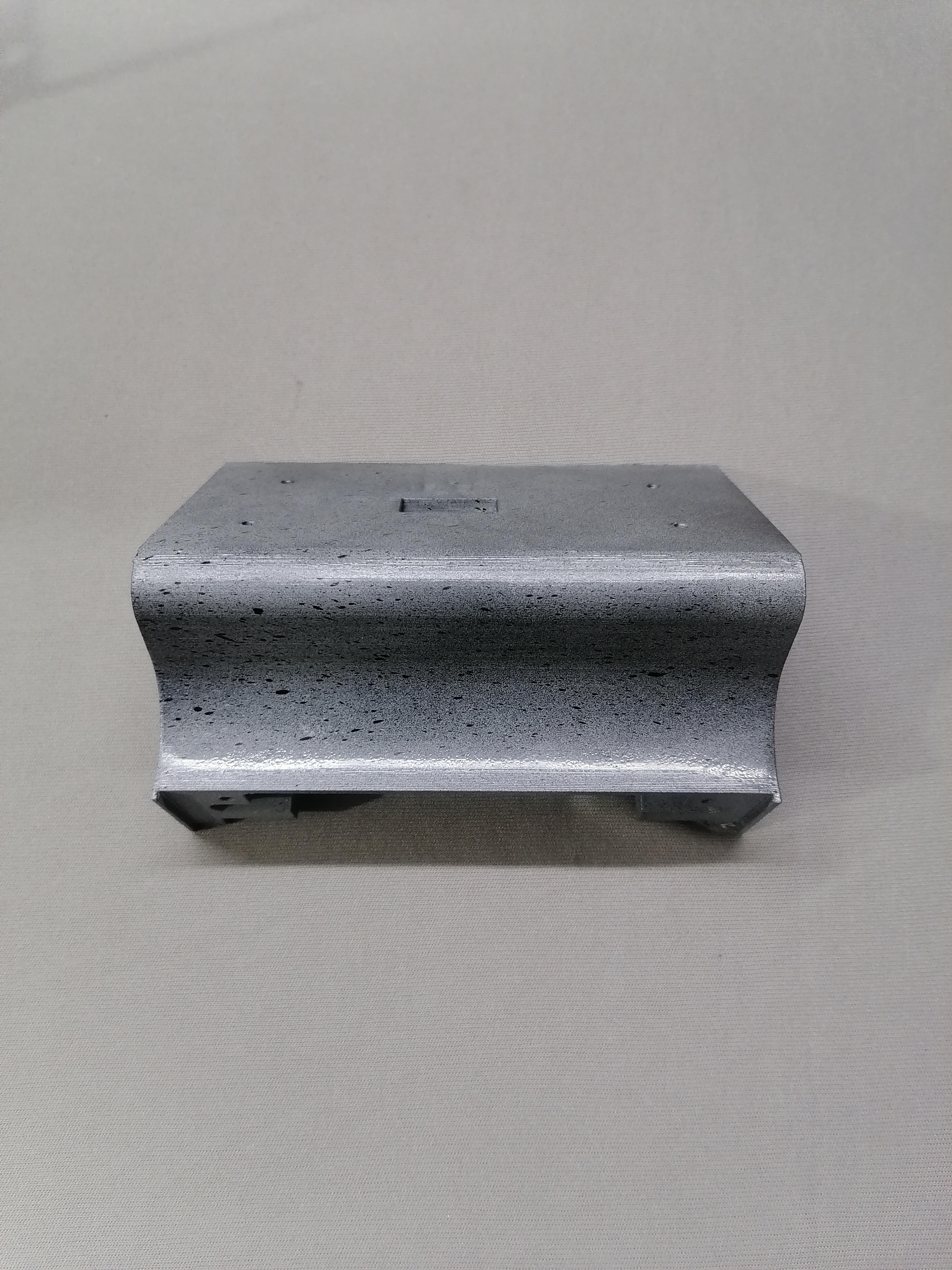
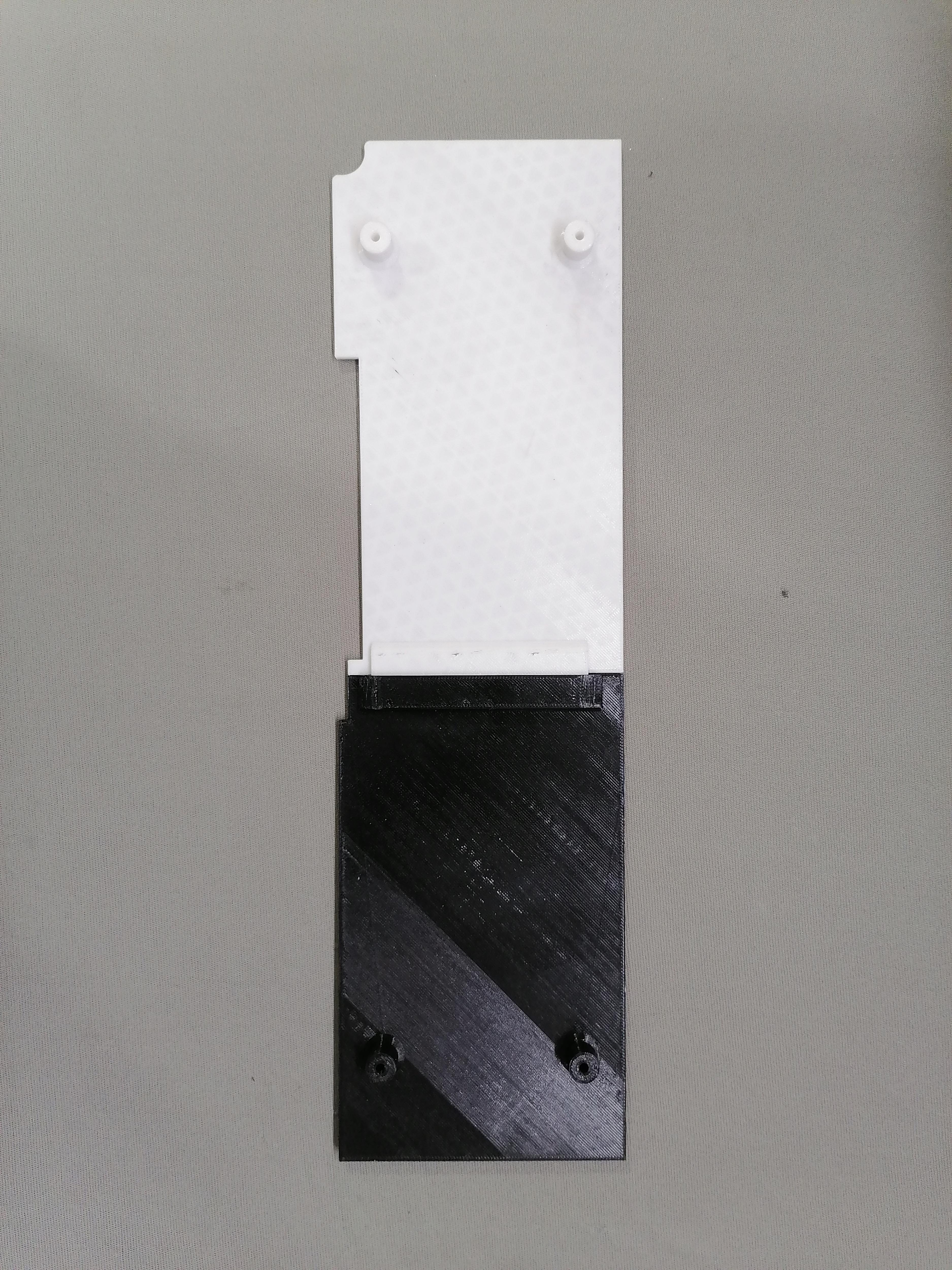
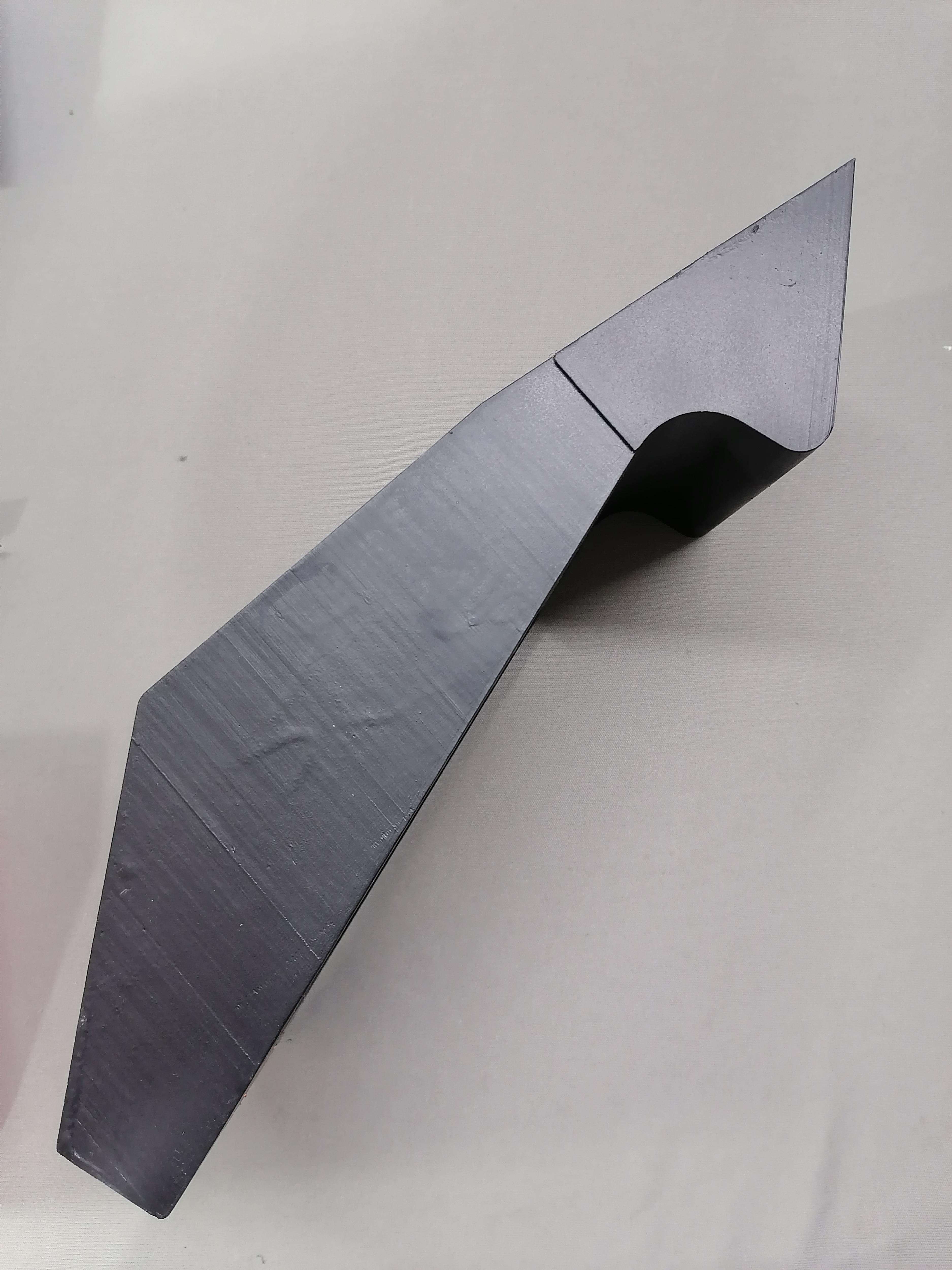
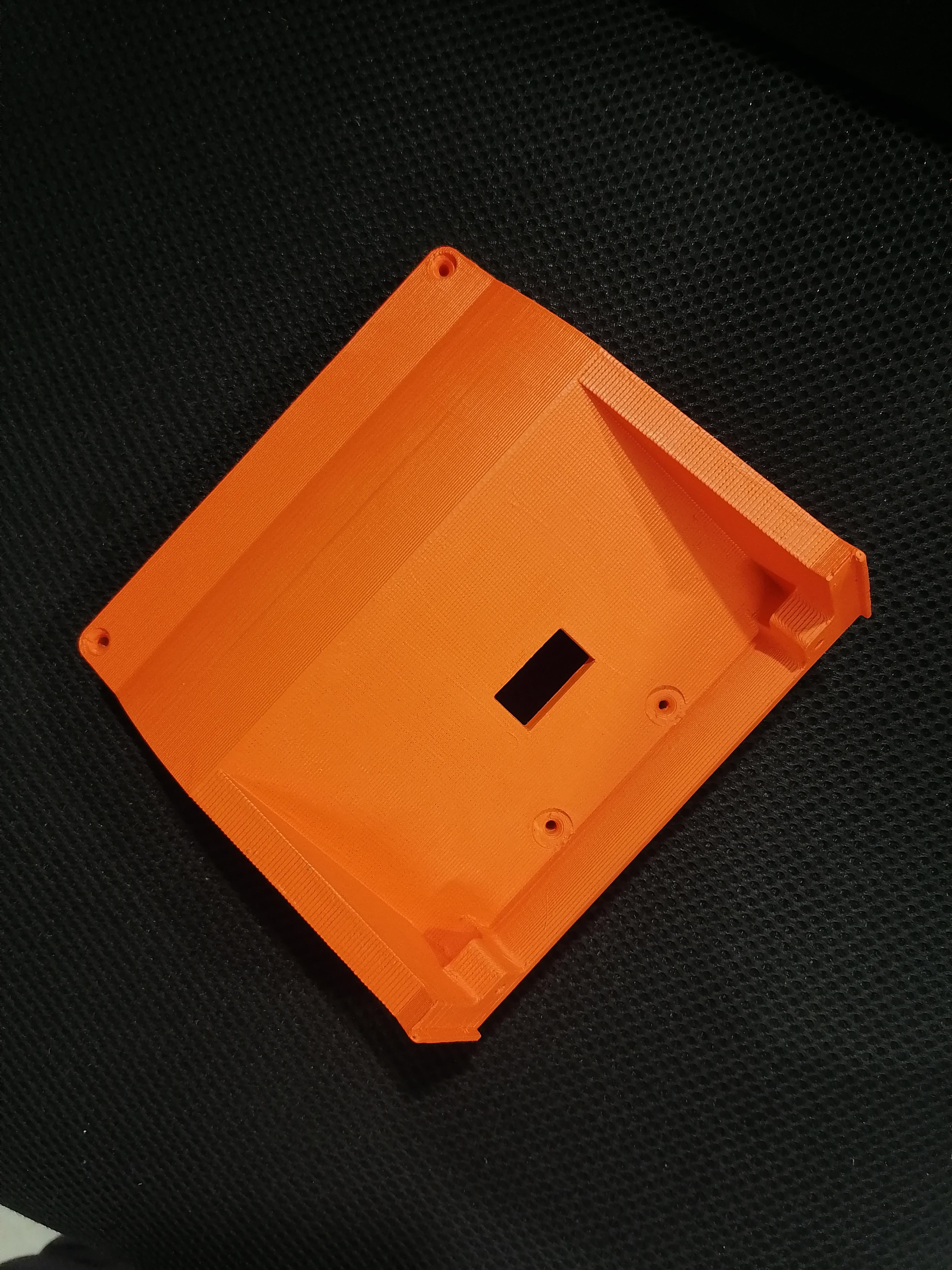
Assembling the Front Parts [Step:1]
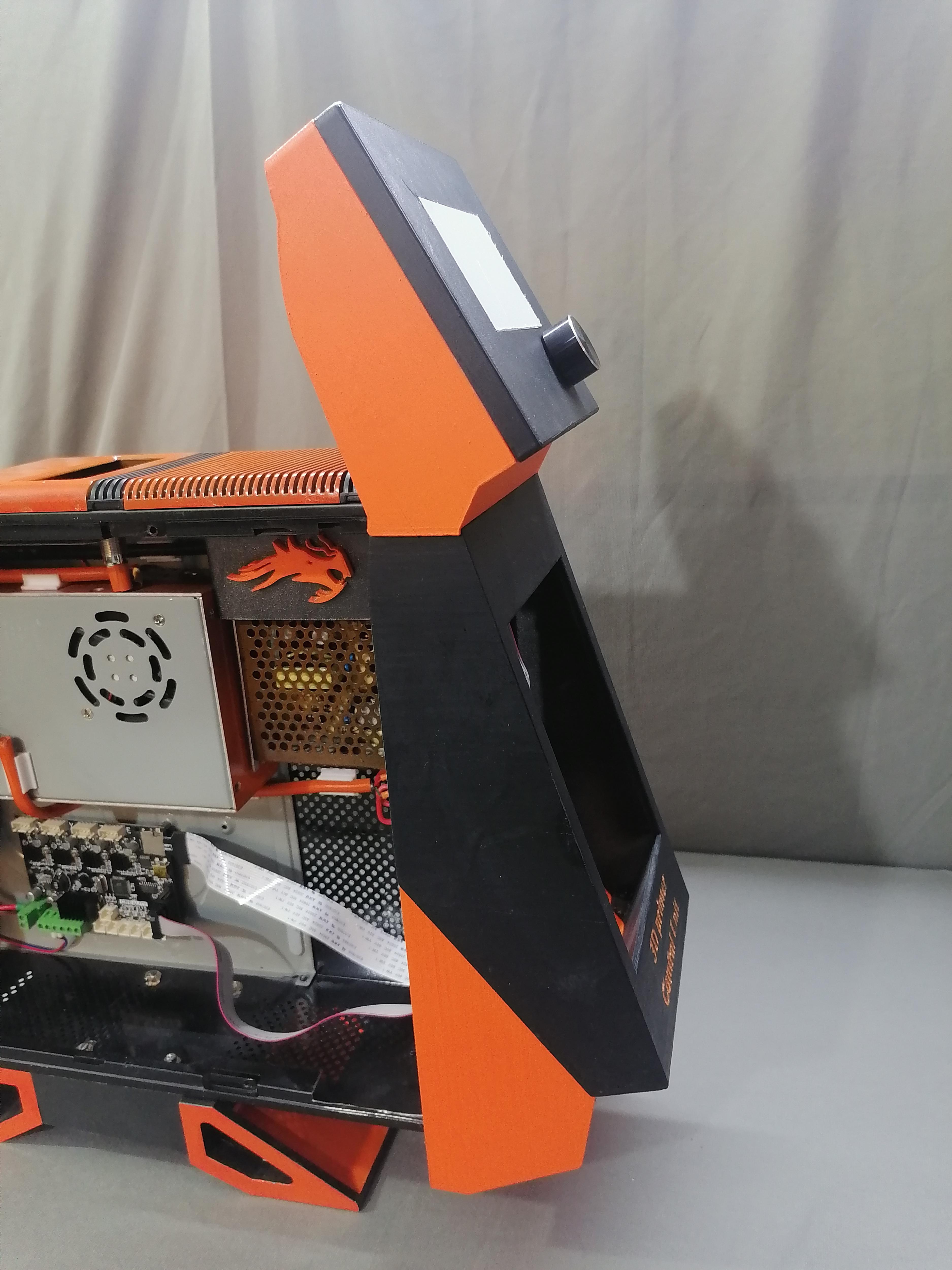
Join the Front- Middle , Front - Bottom and LCD parts together with screws.
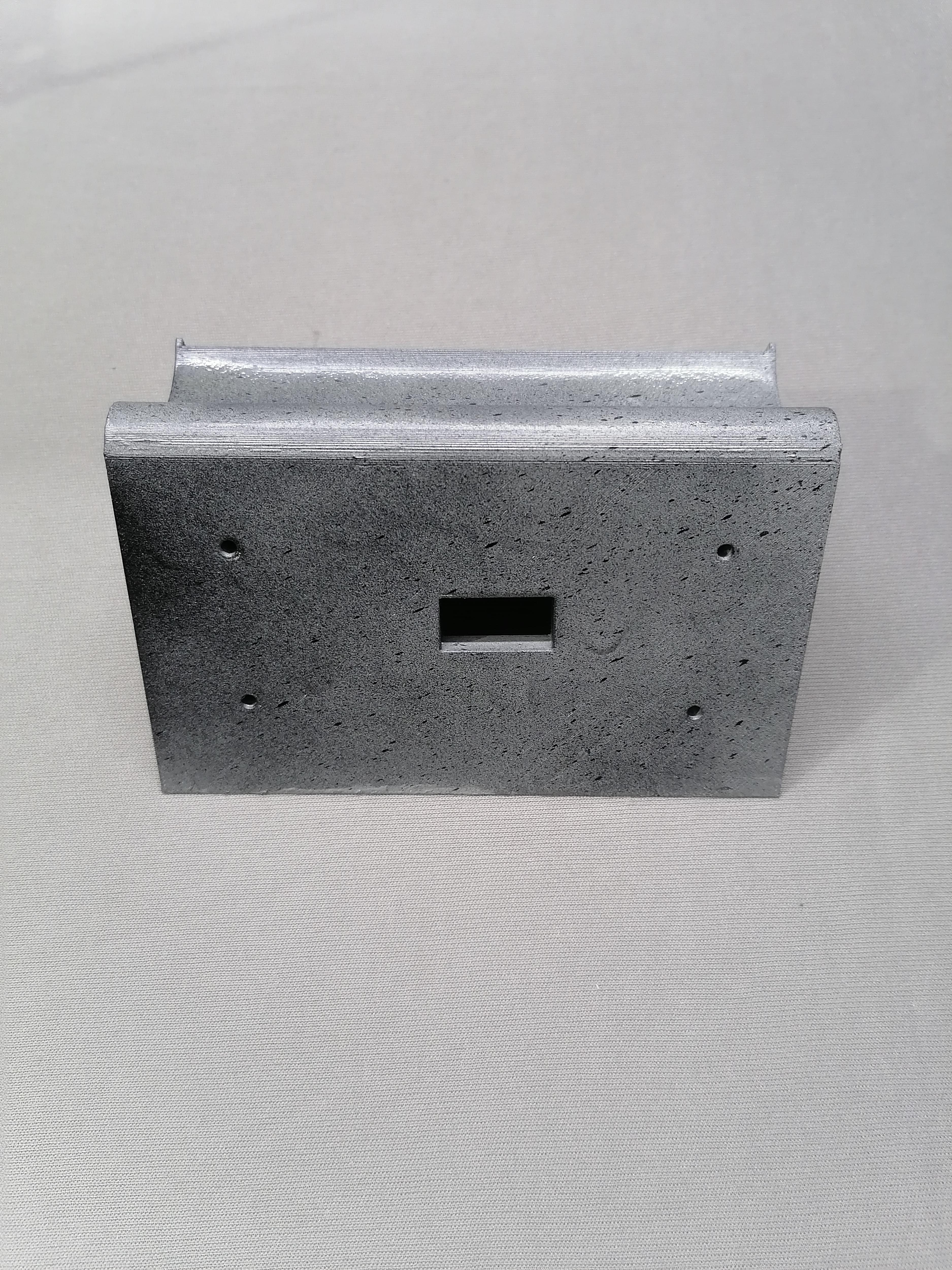
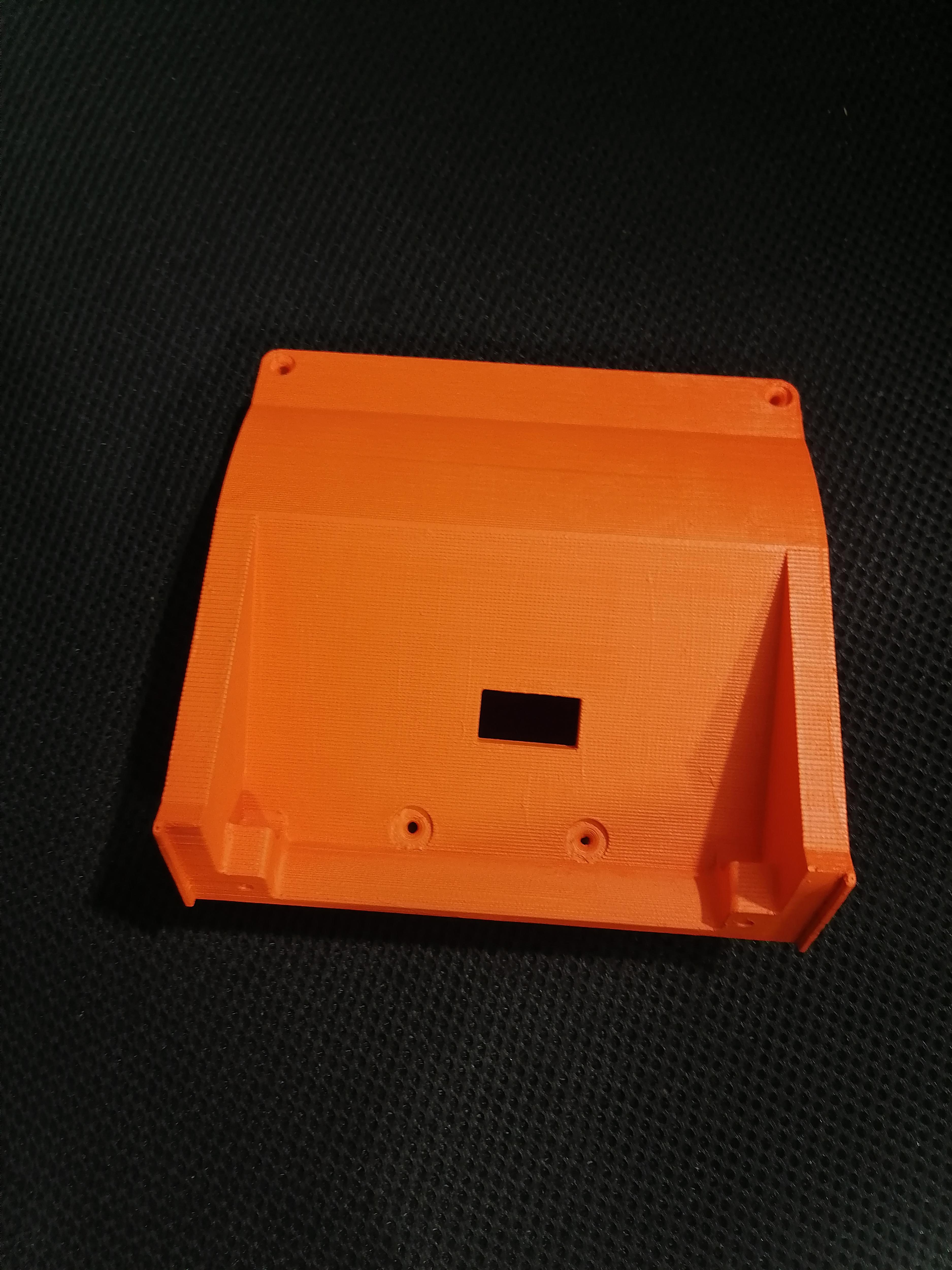
Assembling the Front Parts [Step:2]
Step1: Joint both the Front-middle-1 and Front-bottom-2 parts with screws.
Step2: Drill hole in Front parts and on CPU front side as shown in image.
Note: Refer image for more understanding.
Assembling the Front Parts [Step:3]
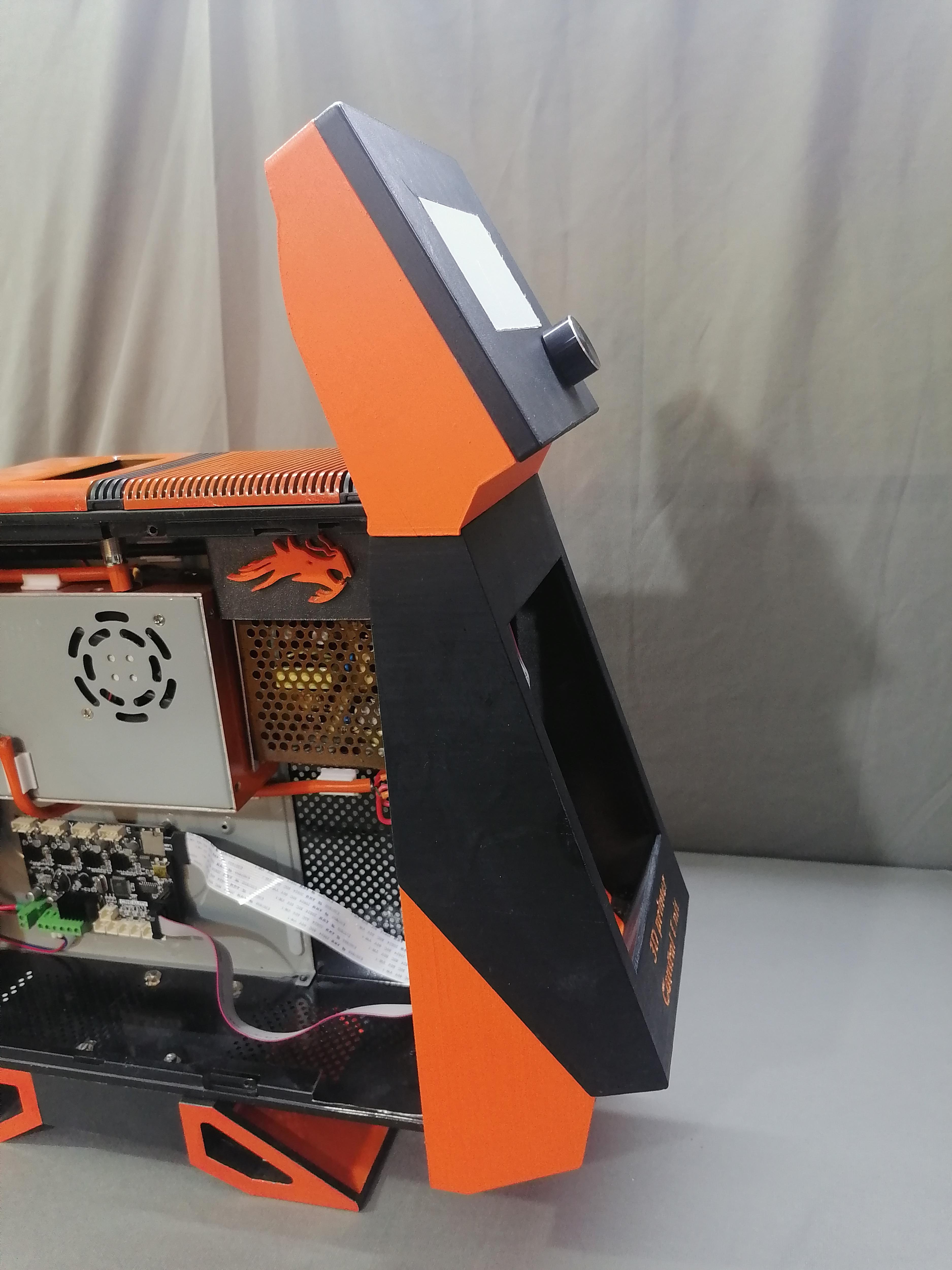
Attach the LCD Assembled part.
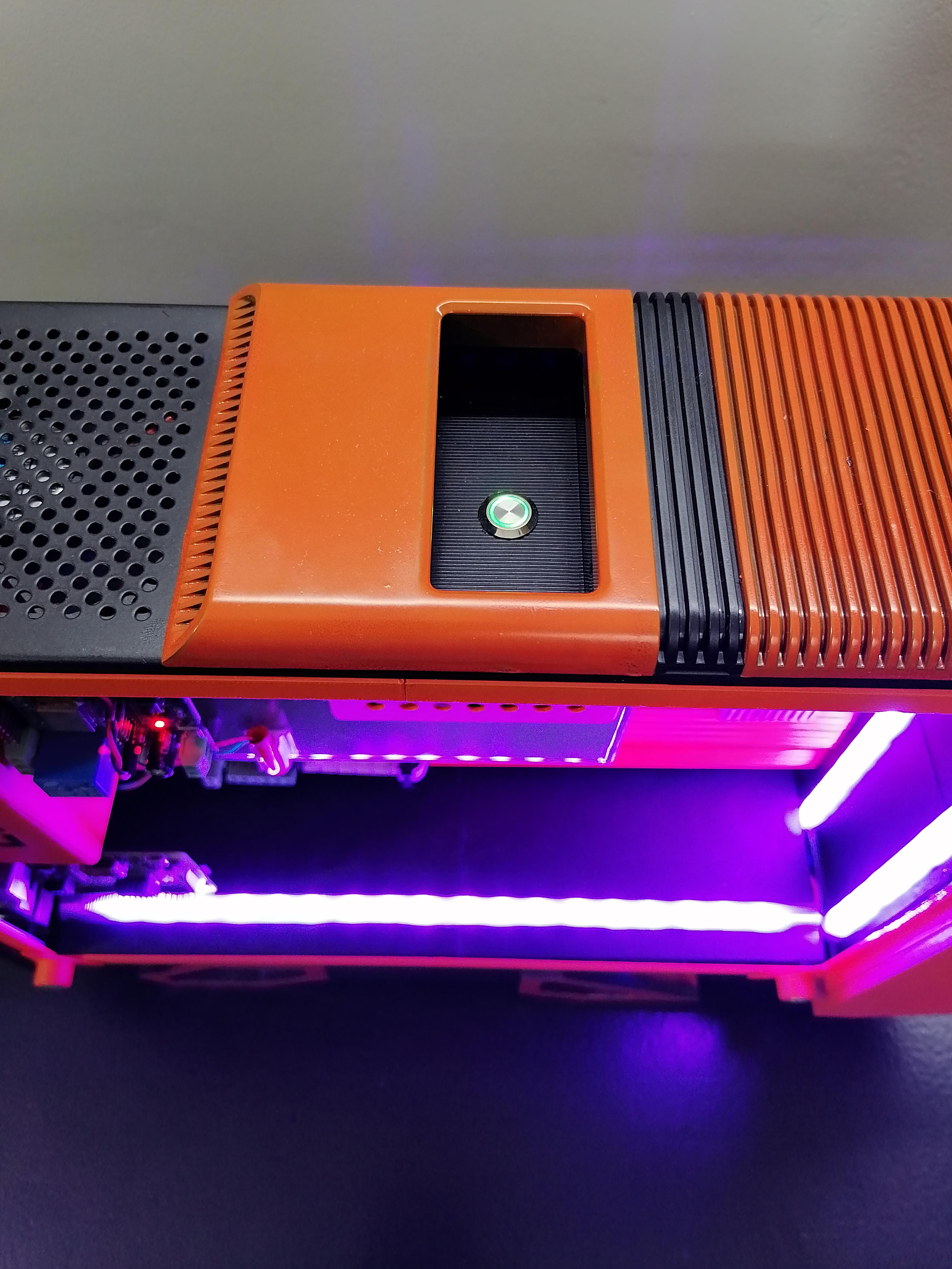
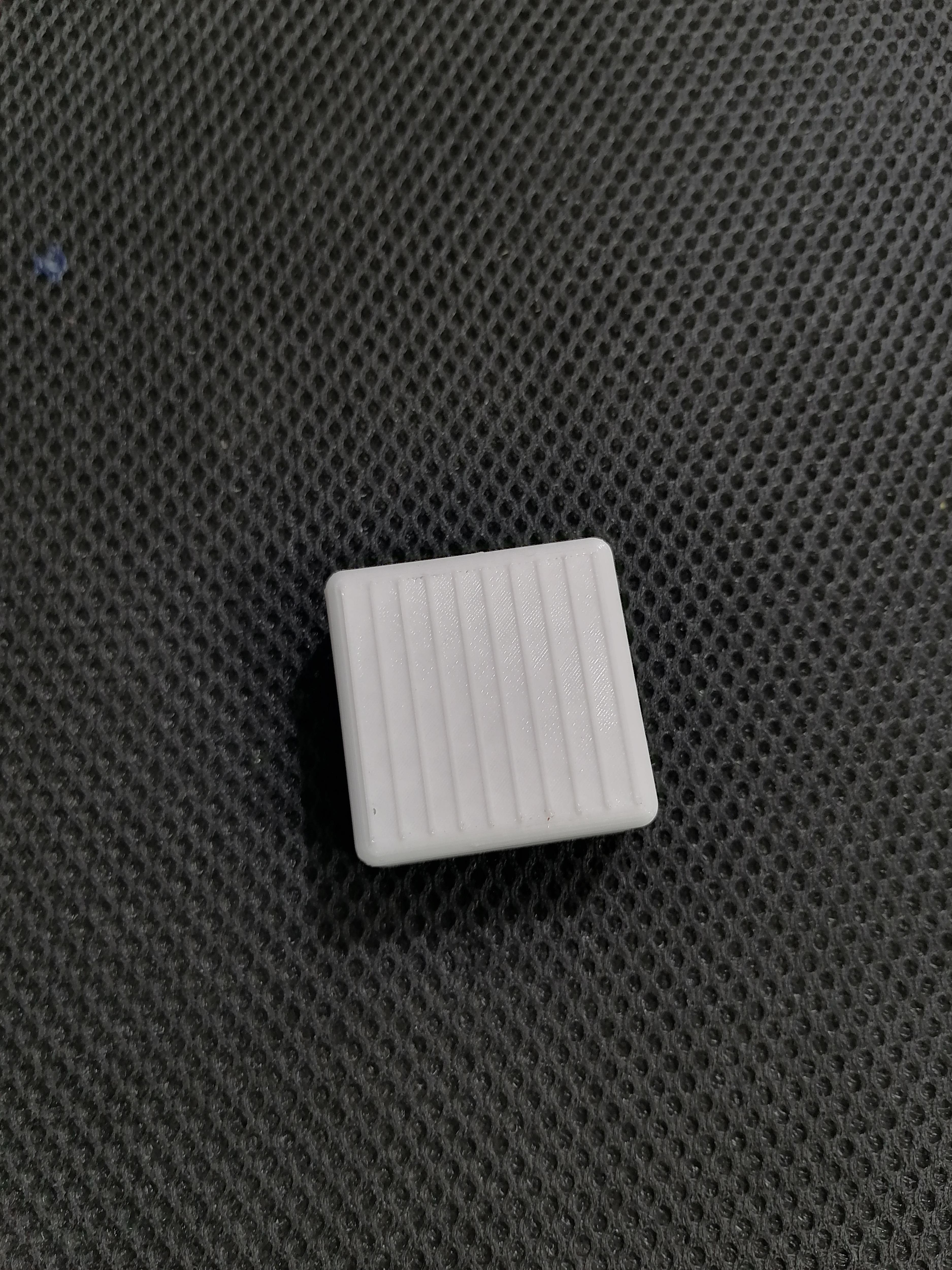
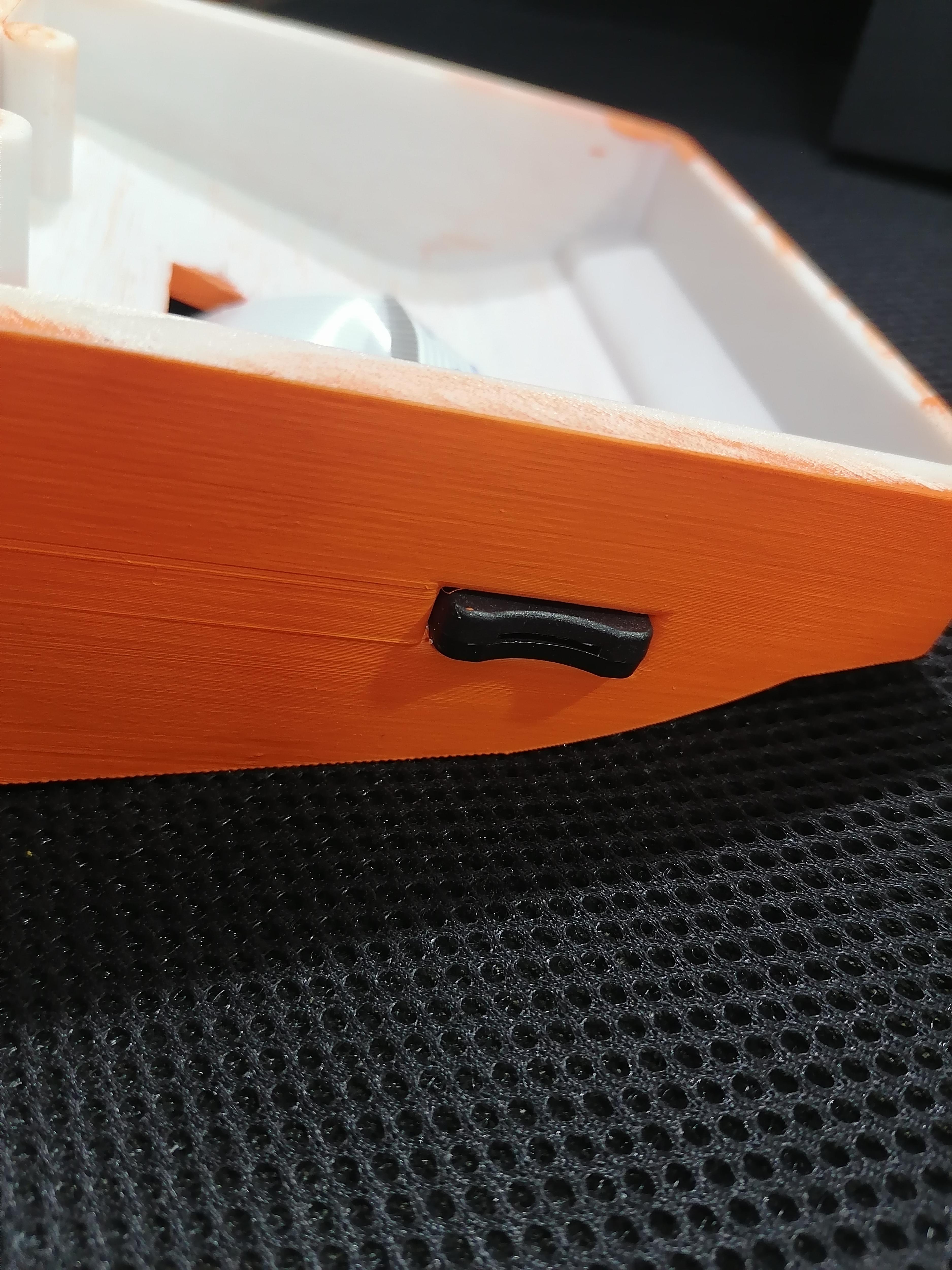
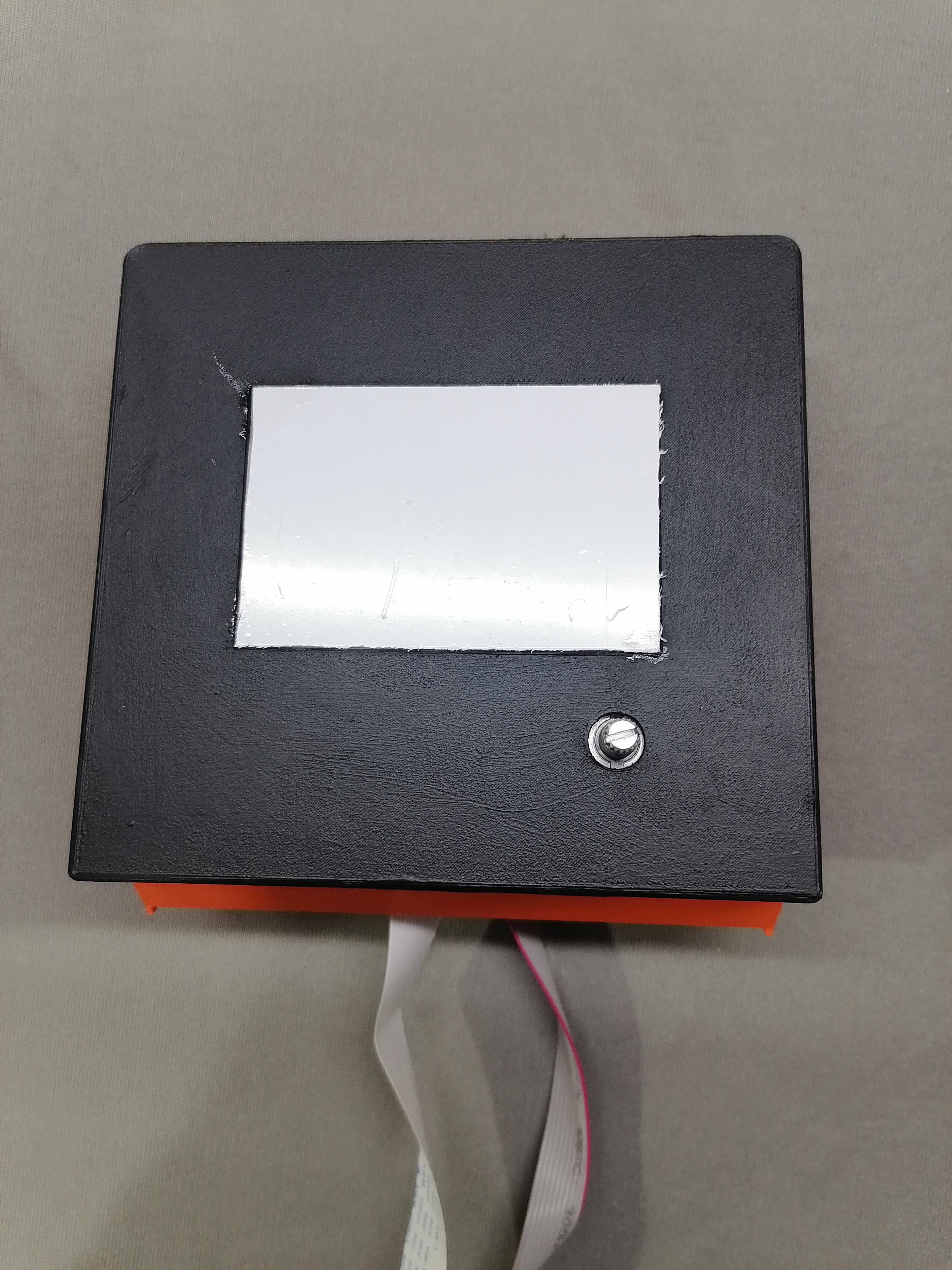
ON/OFF Switch of 3D Printer
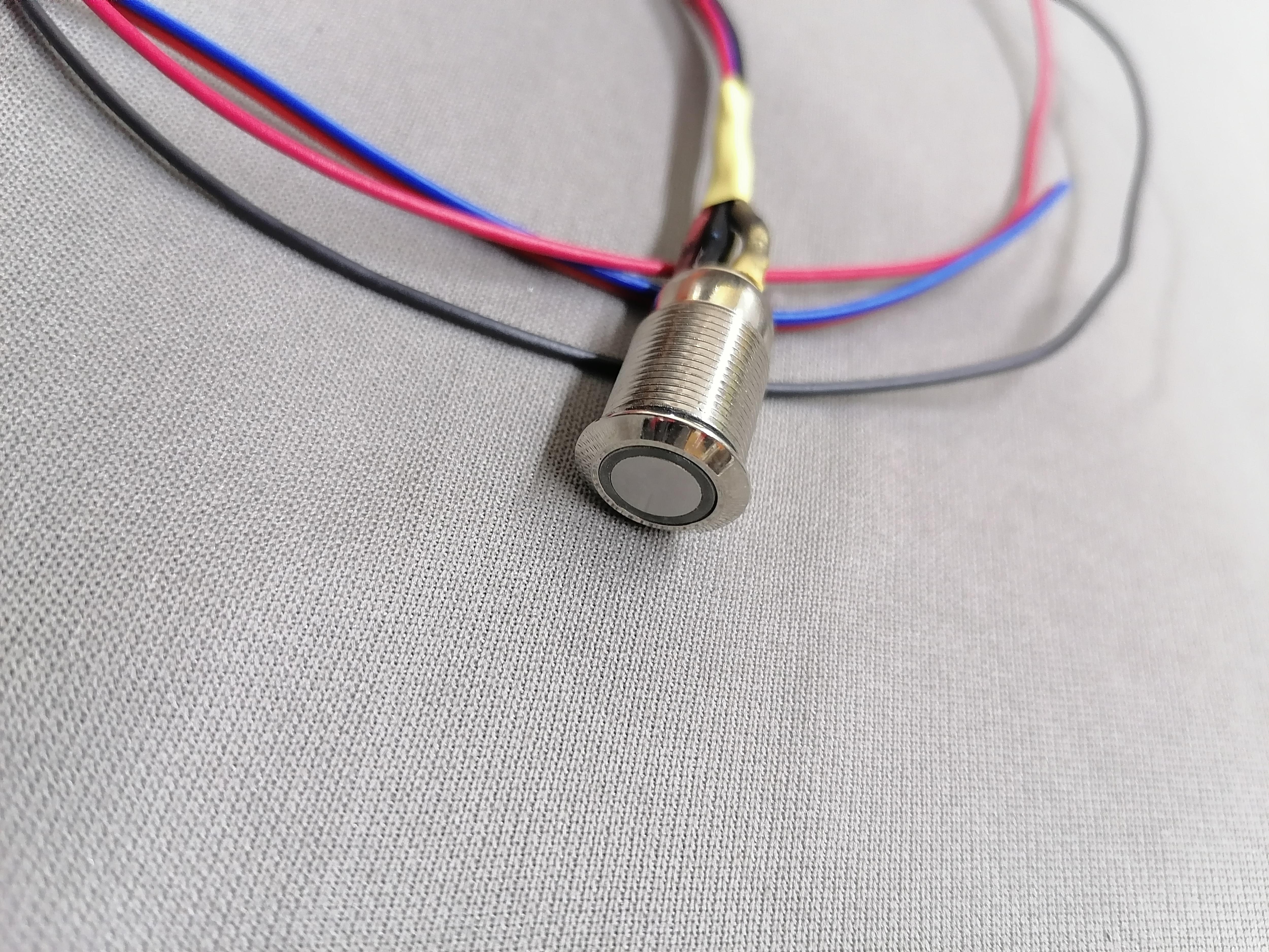
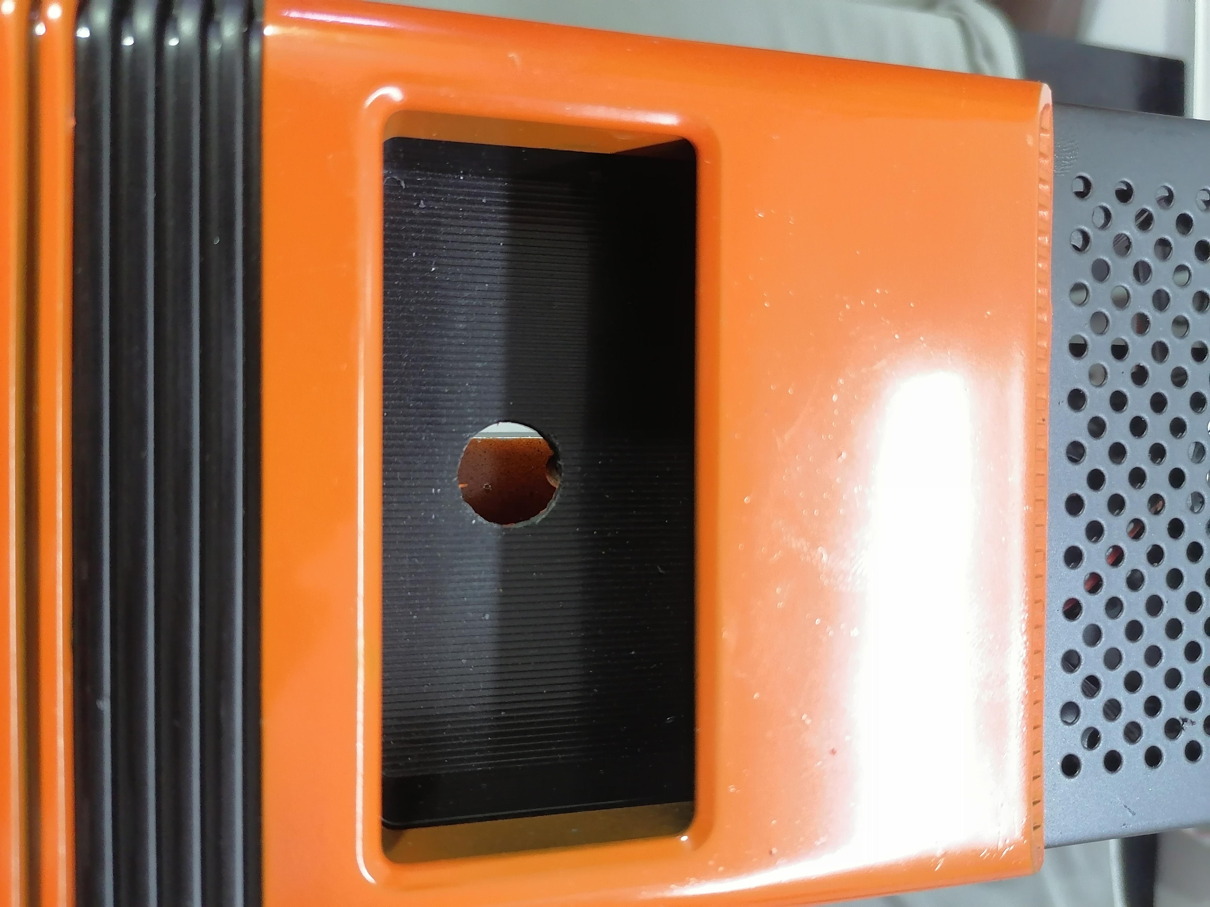
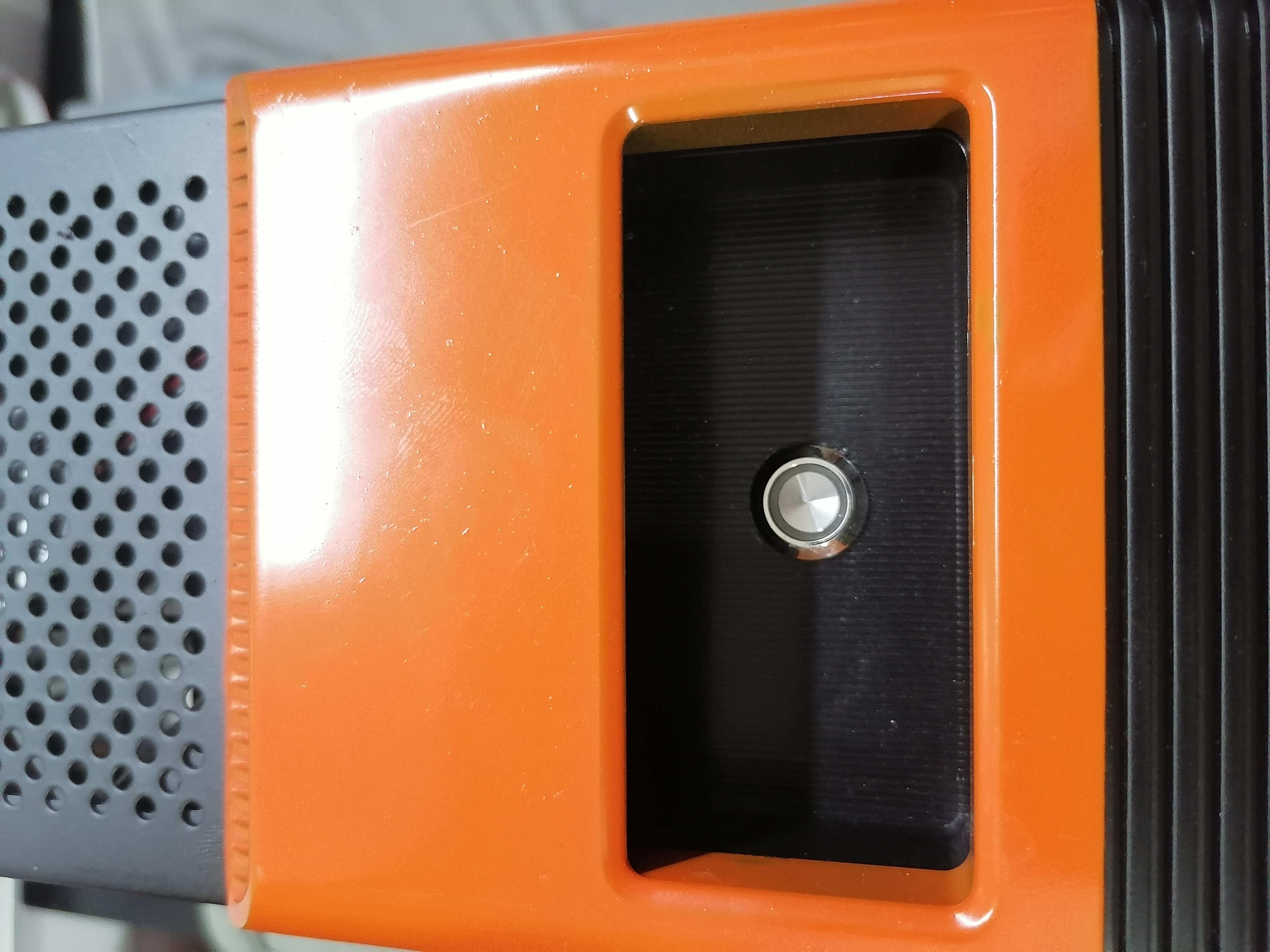
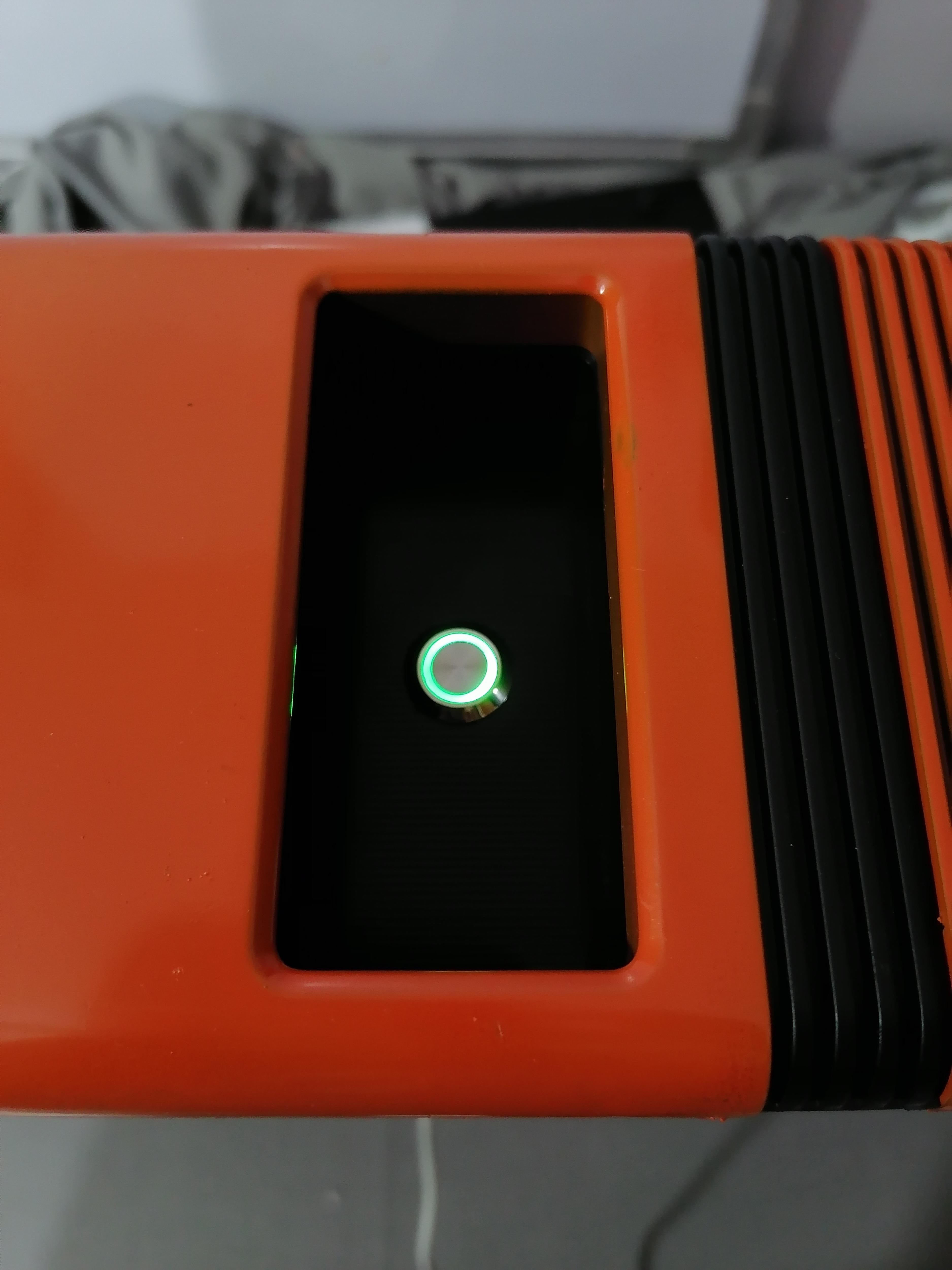
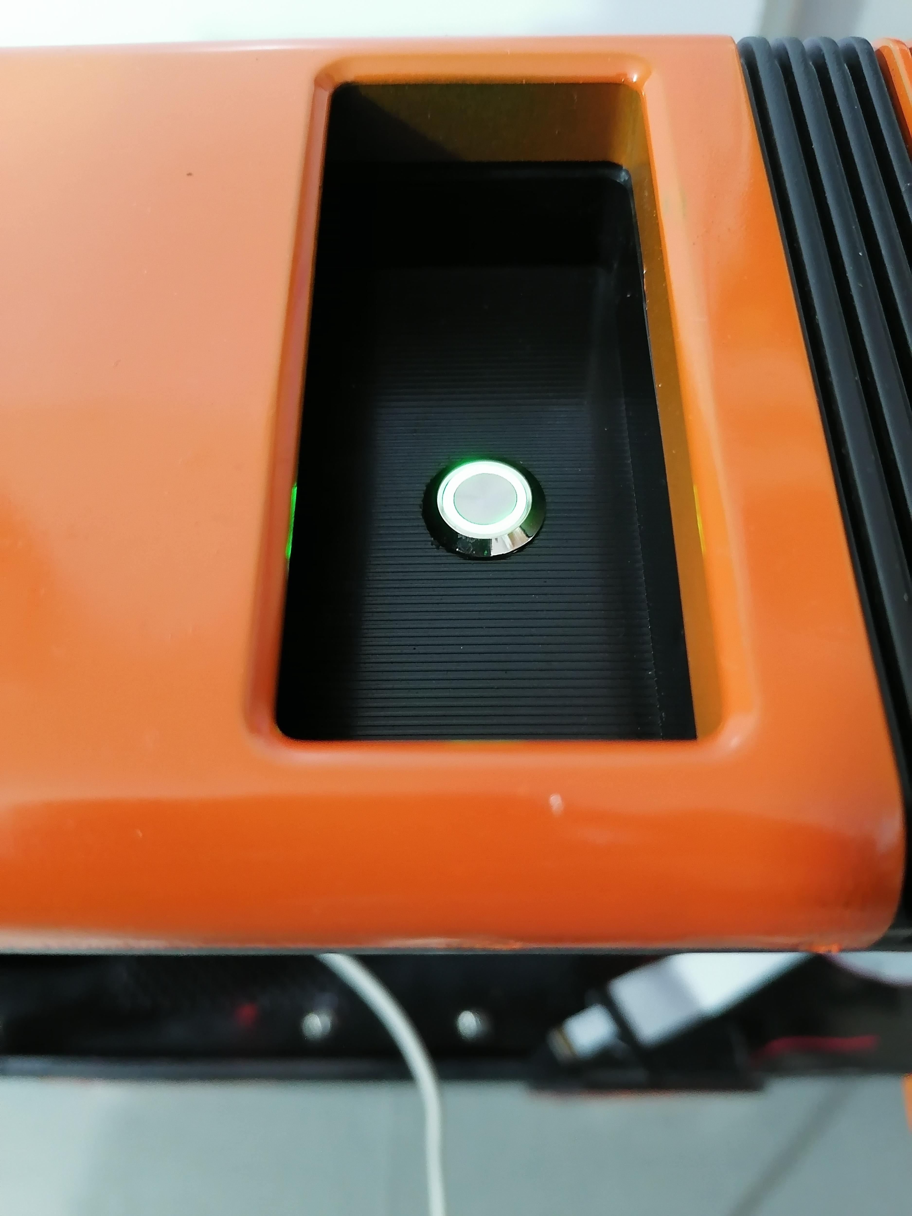
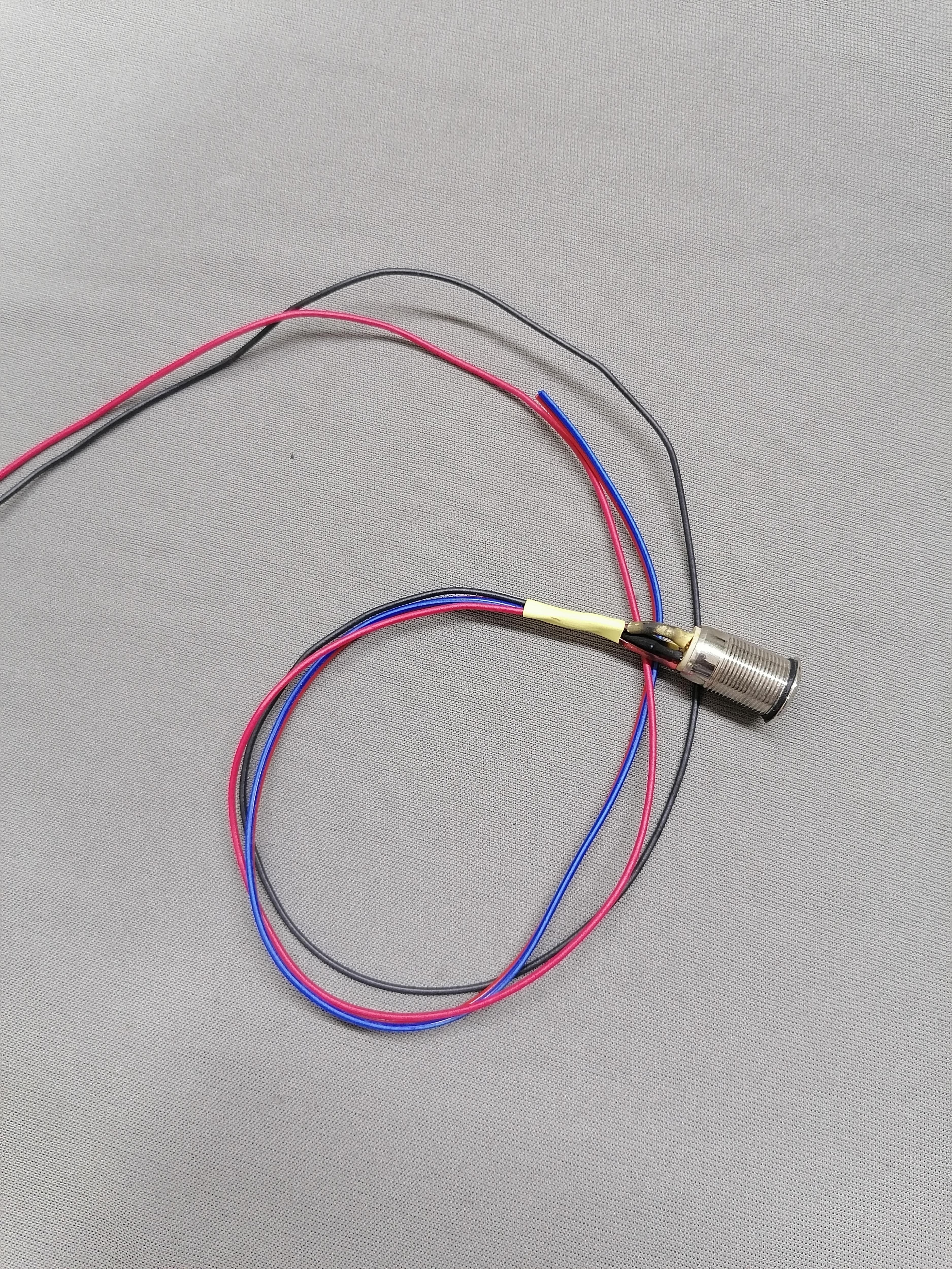
Here I am using the Momentary Switch to turn ON/OFF 3D printer Manually.
This switch connected to the WiFi Relay Module.
Make the 12mm Diameter hole and insert the switch.
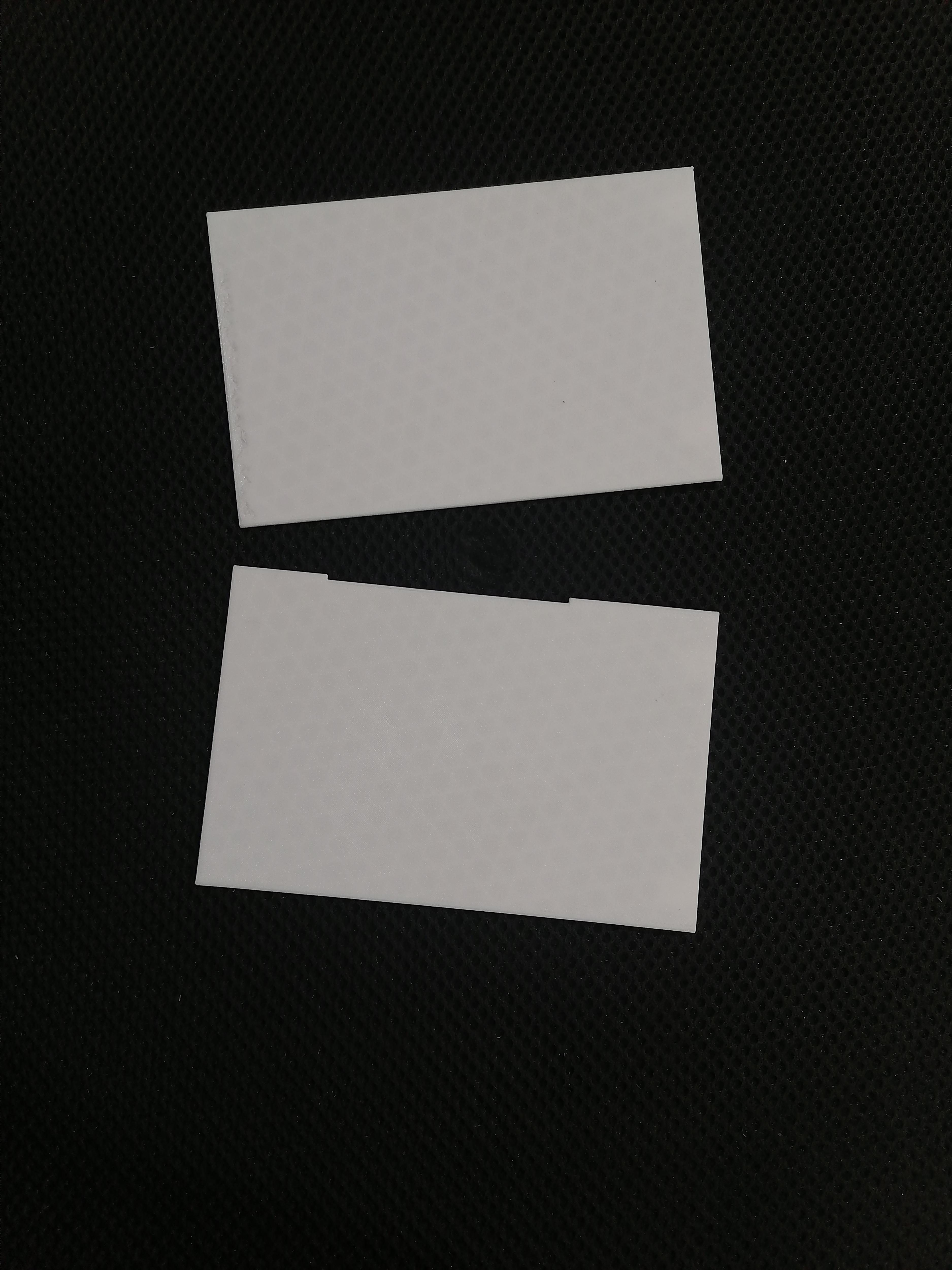
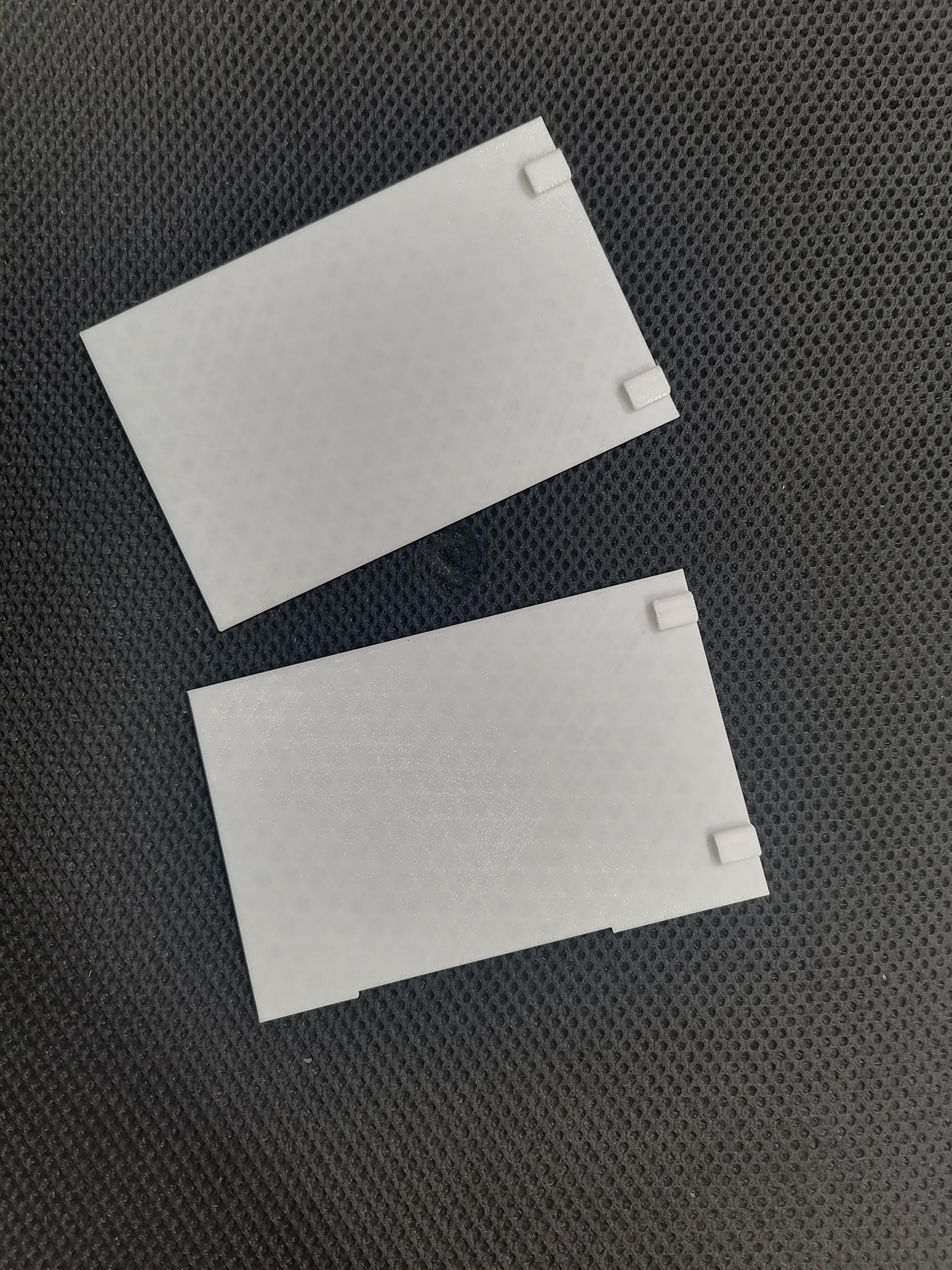
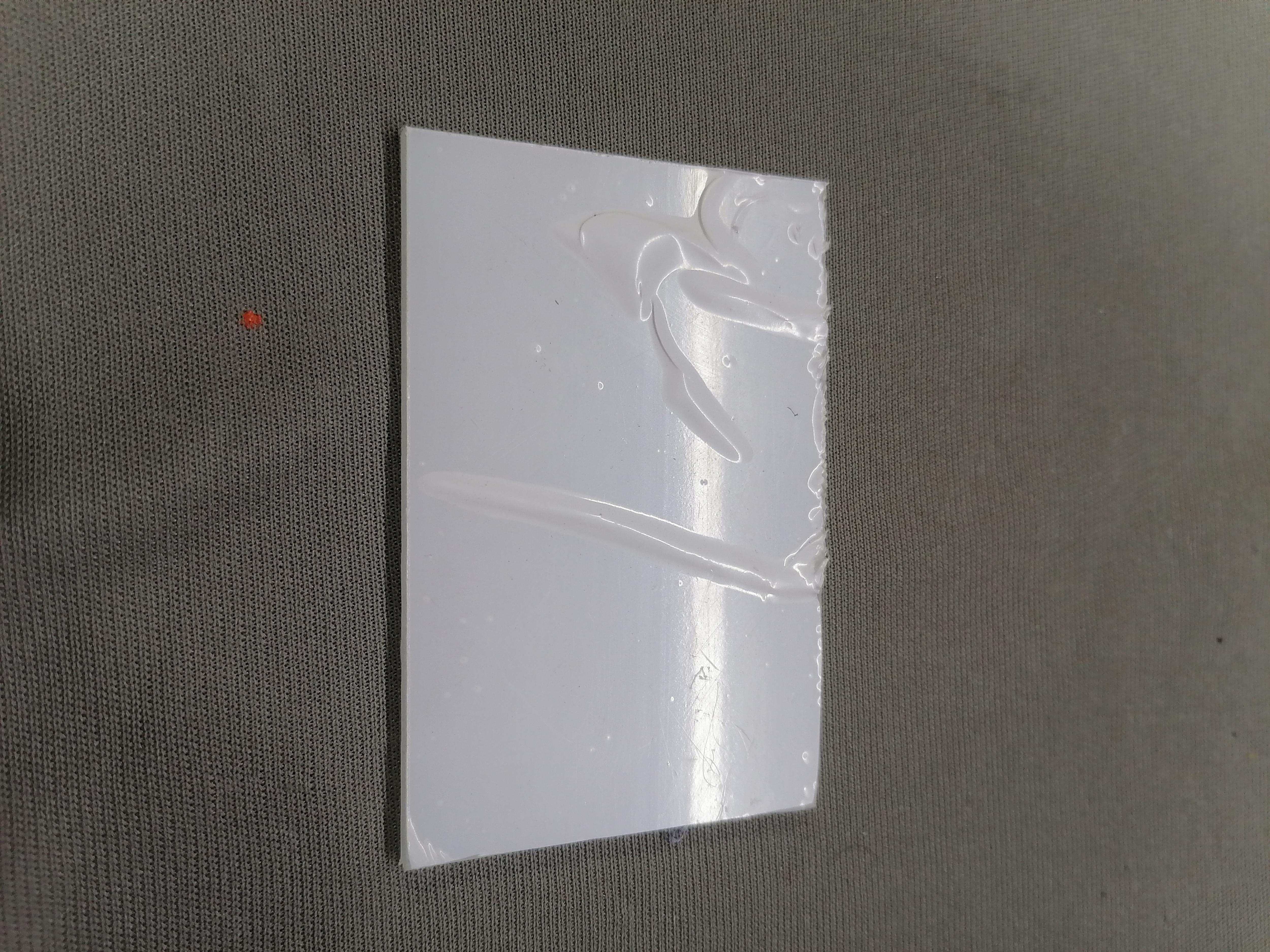
Stick Mirror Film on Acrylic Sheet
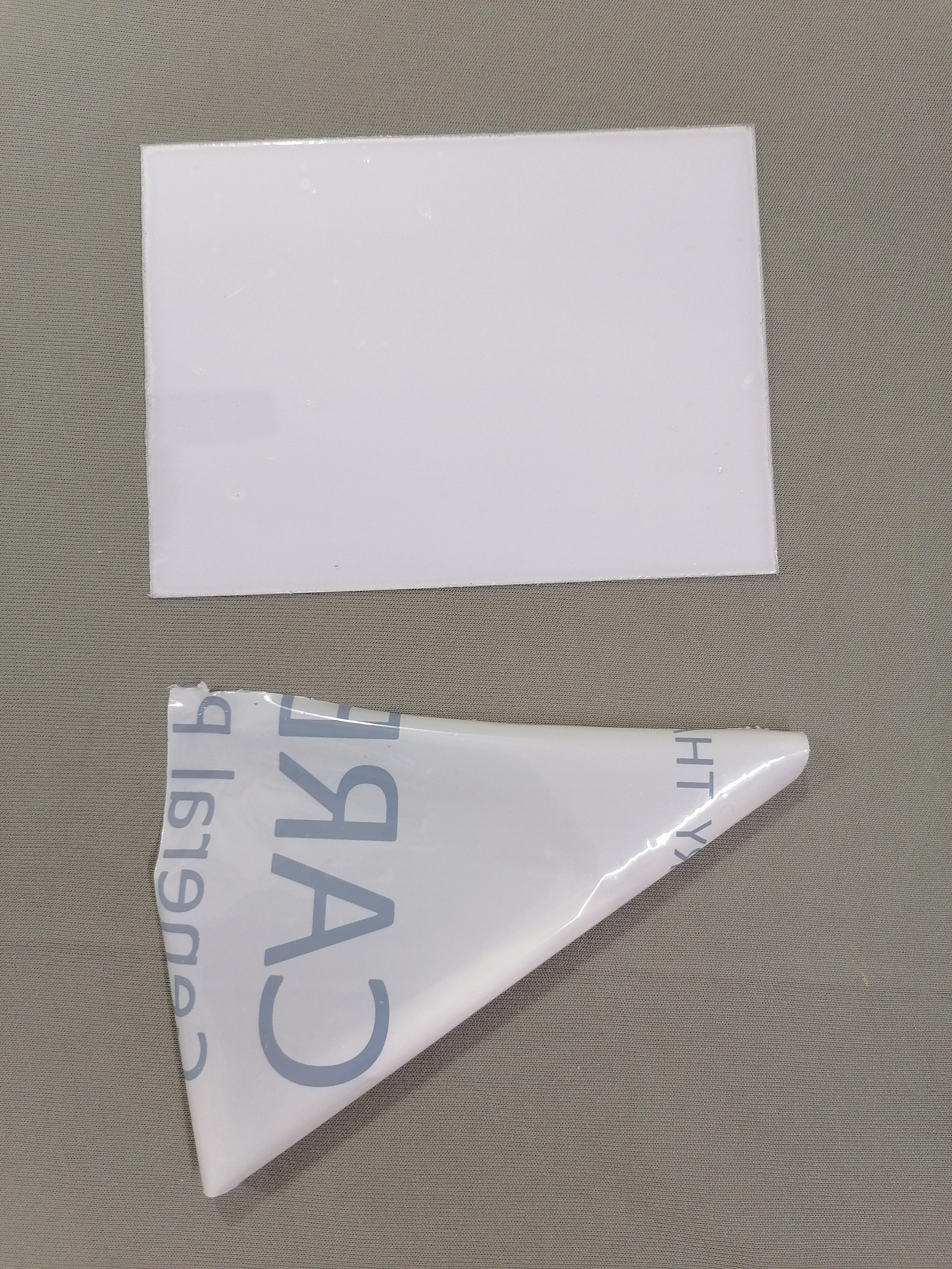
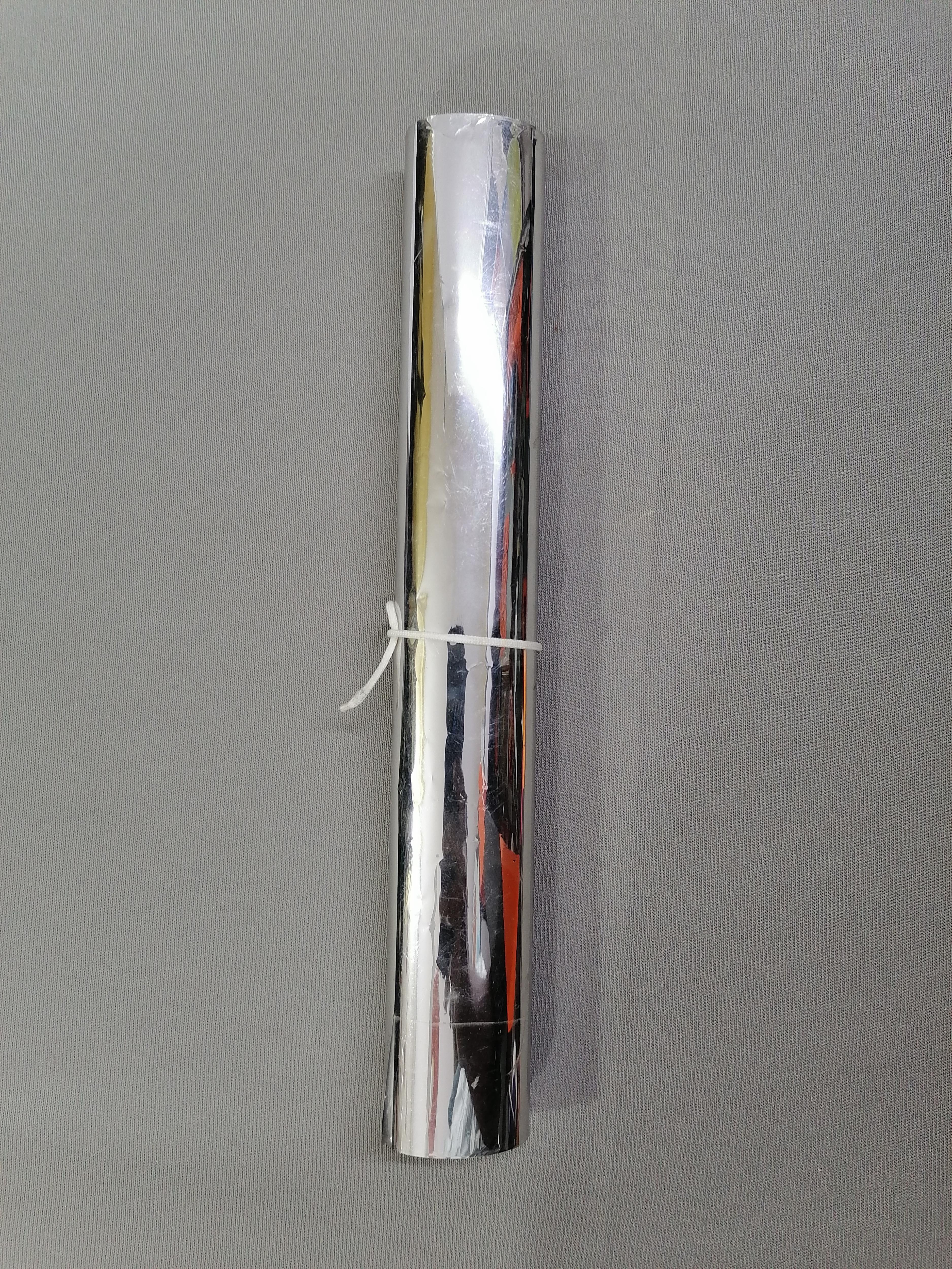
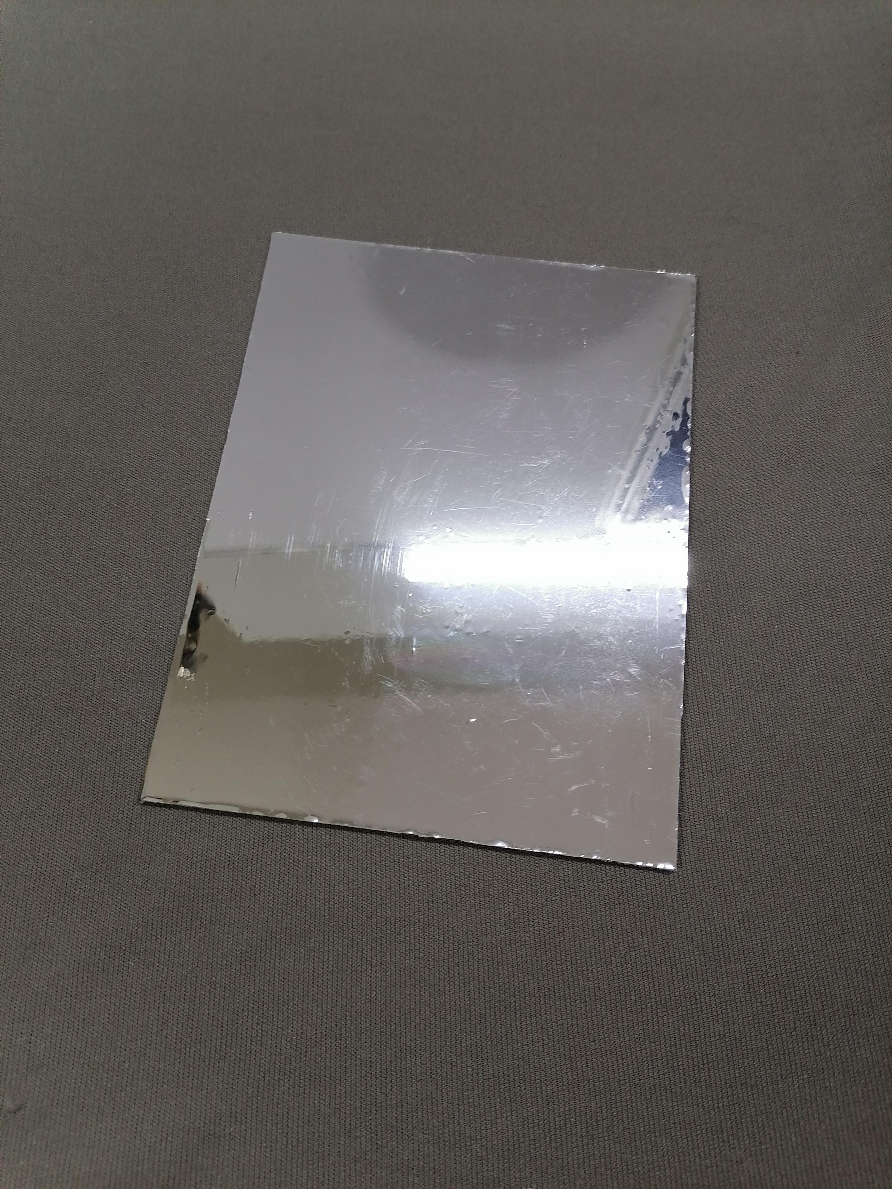
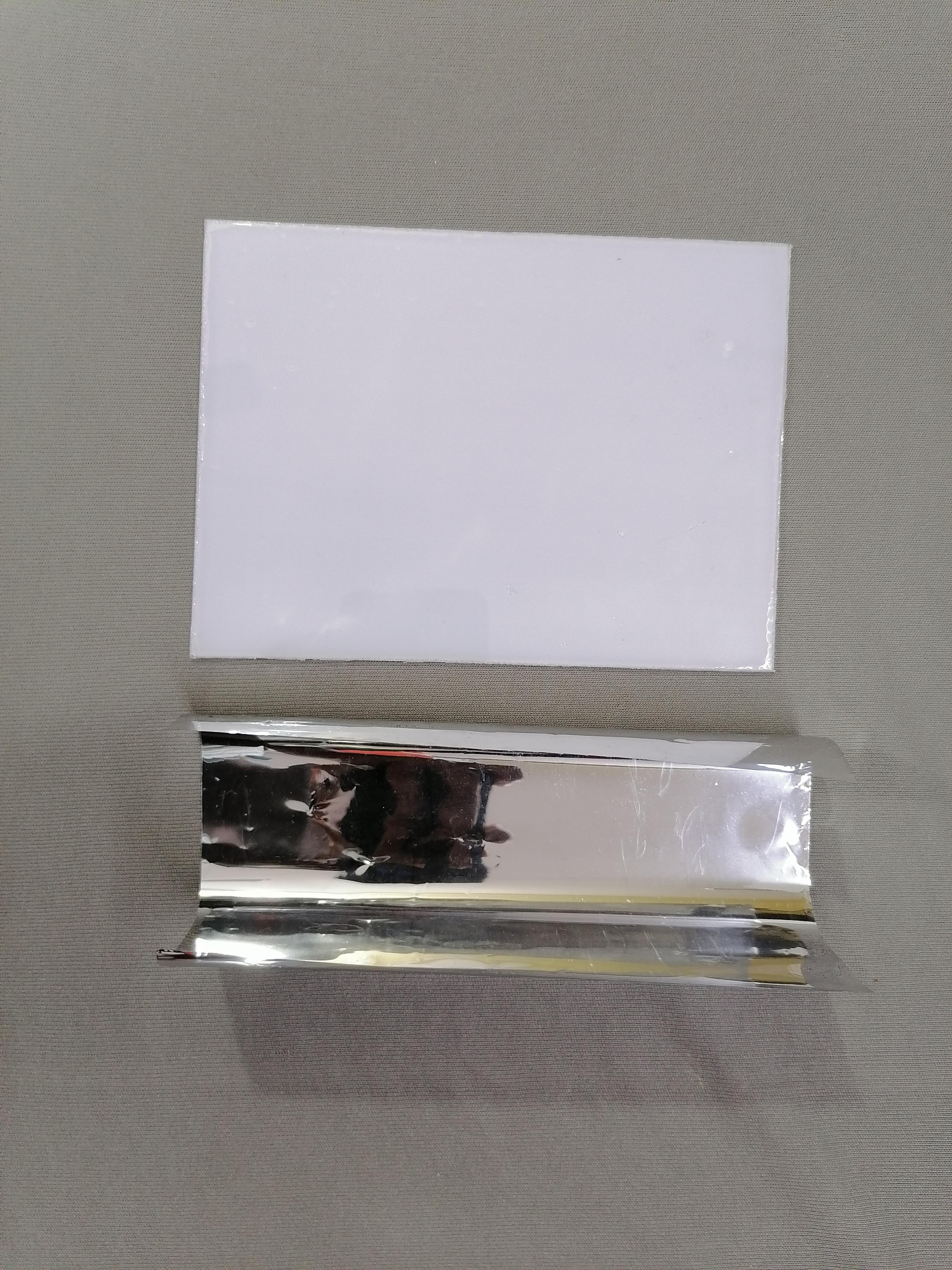
Cut the acrylic sheet as per given dimensions then stick the mirror film on it. (This is part optional)
Downloads
G-code Path Generated in Fusion360
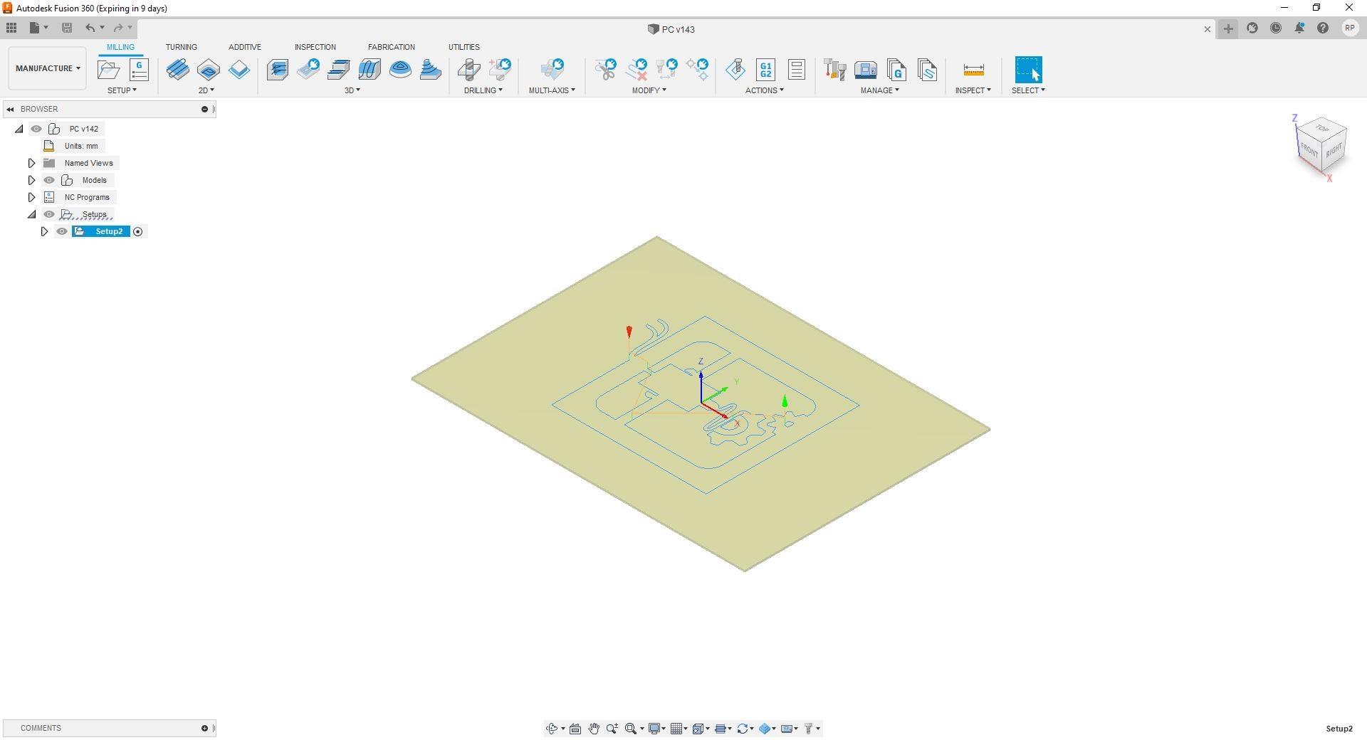
Download the G-code file for Engraving printer symbol.
Downloads
CNC Engraving
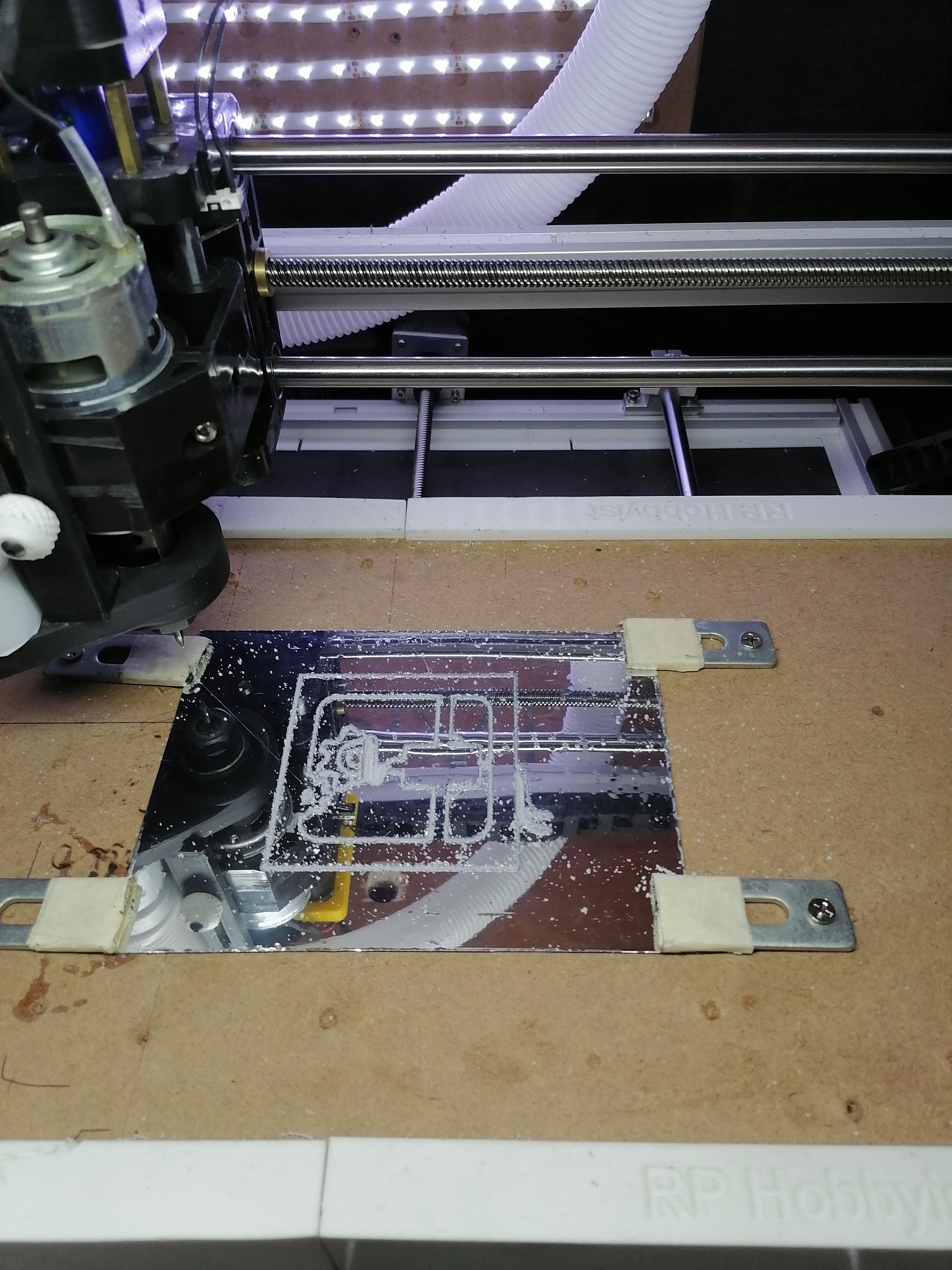
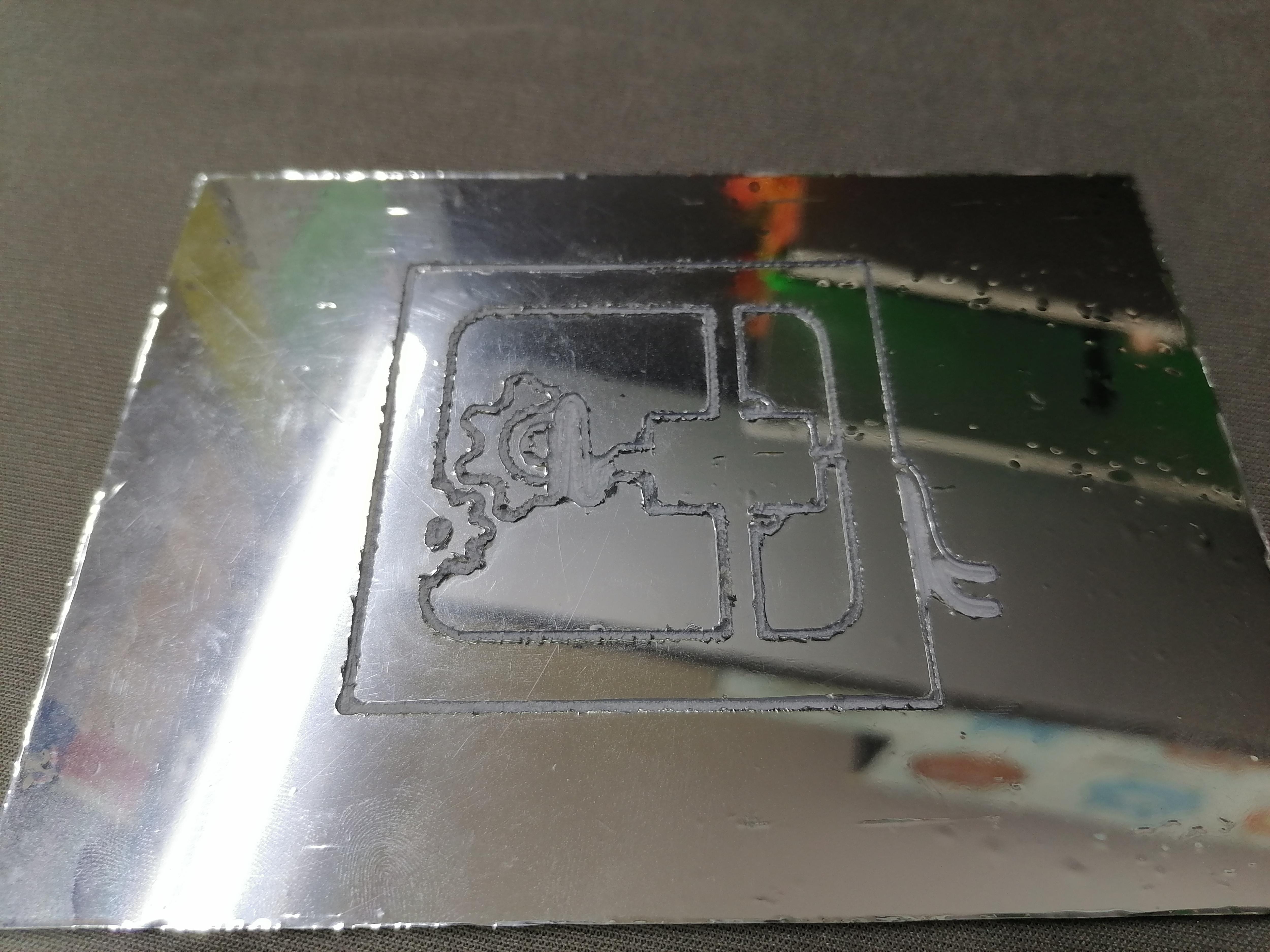
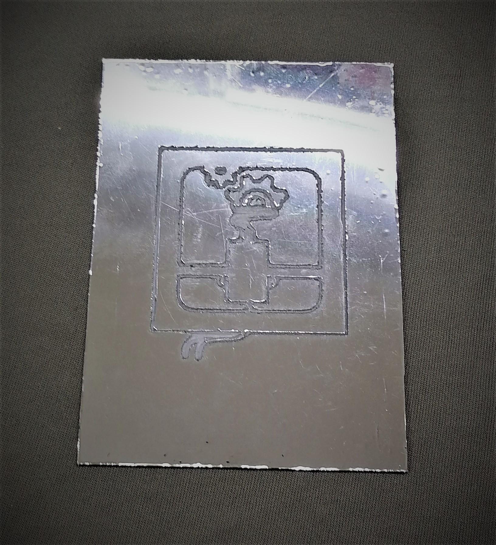
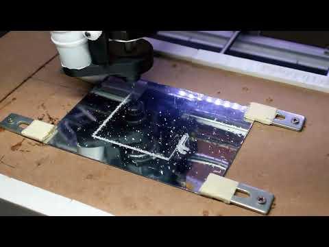
Do the engraving on the where you stick the mirror film.
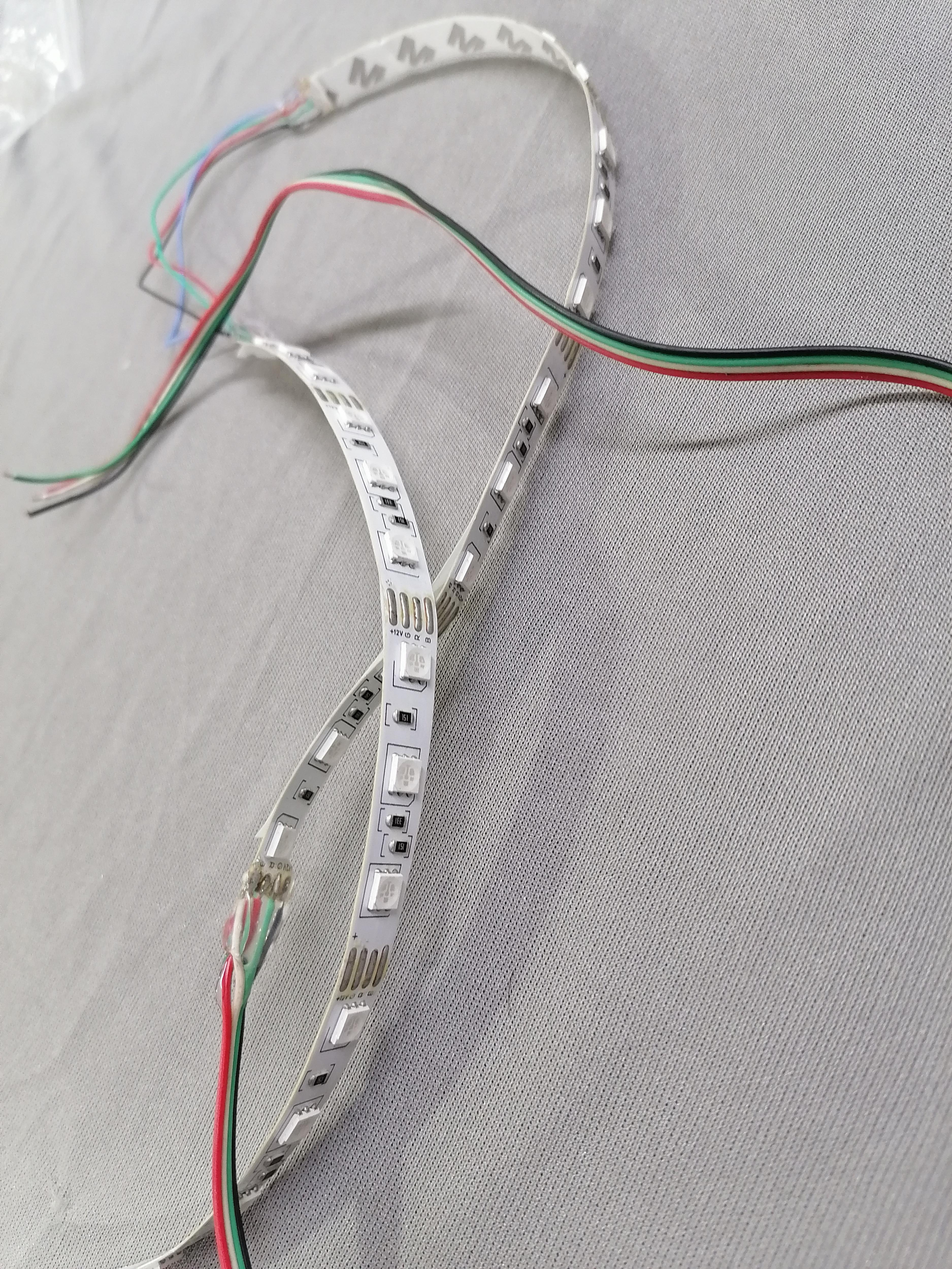
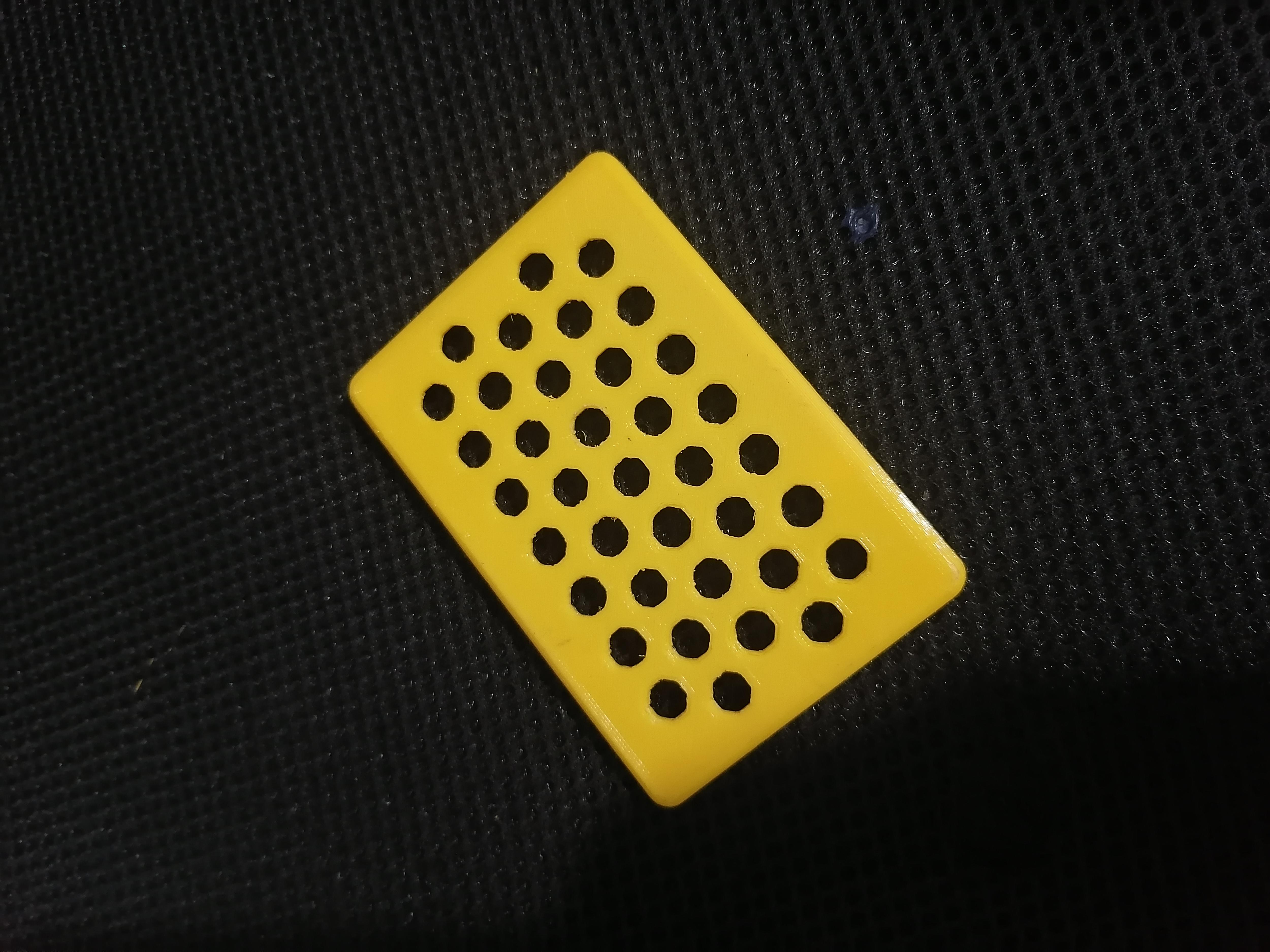
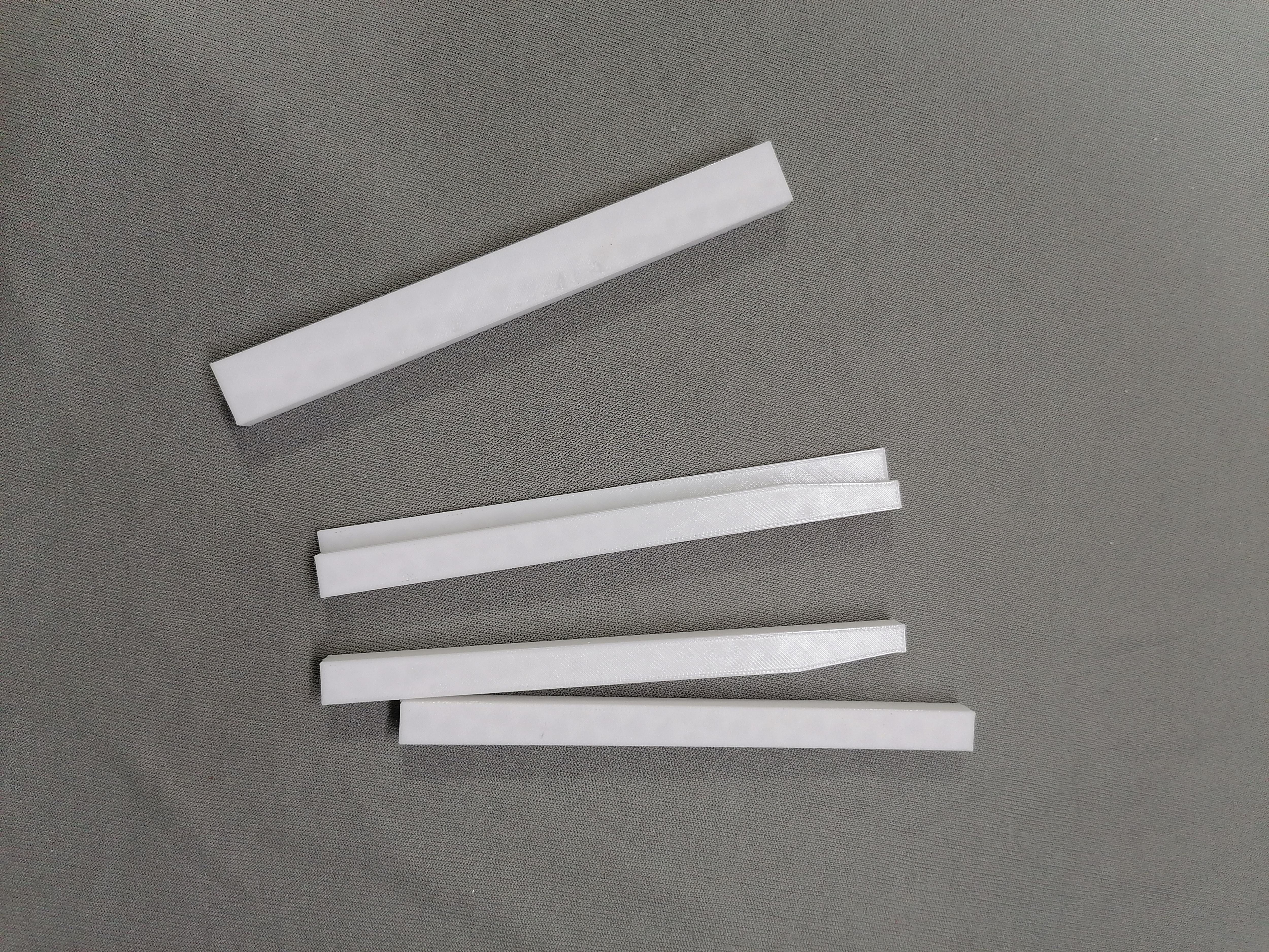
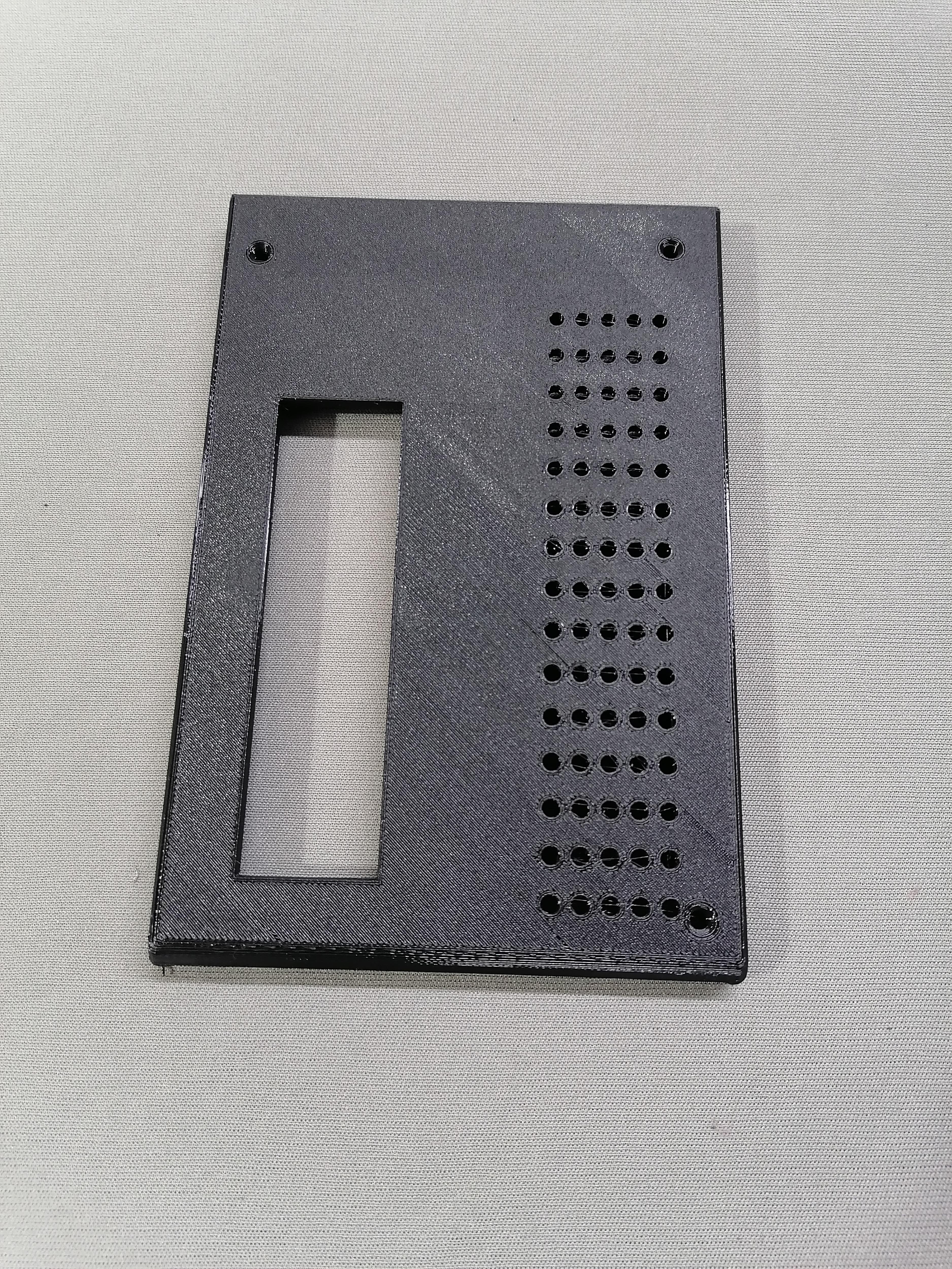
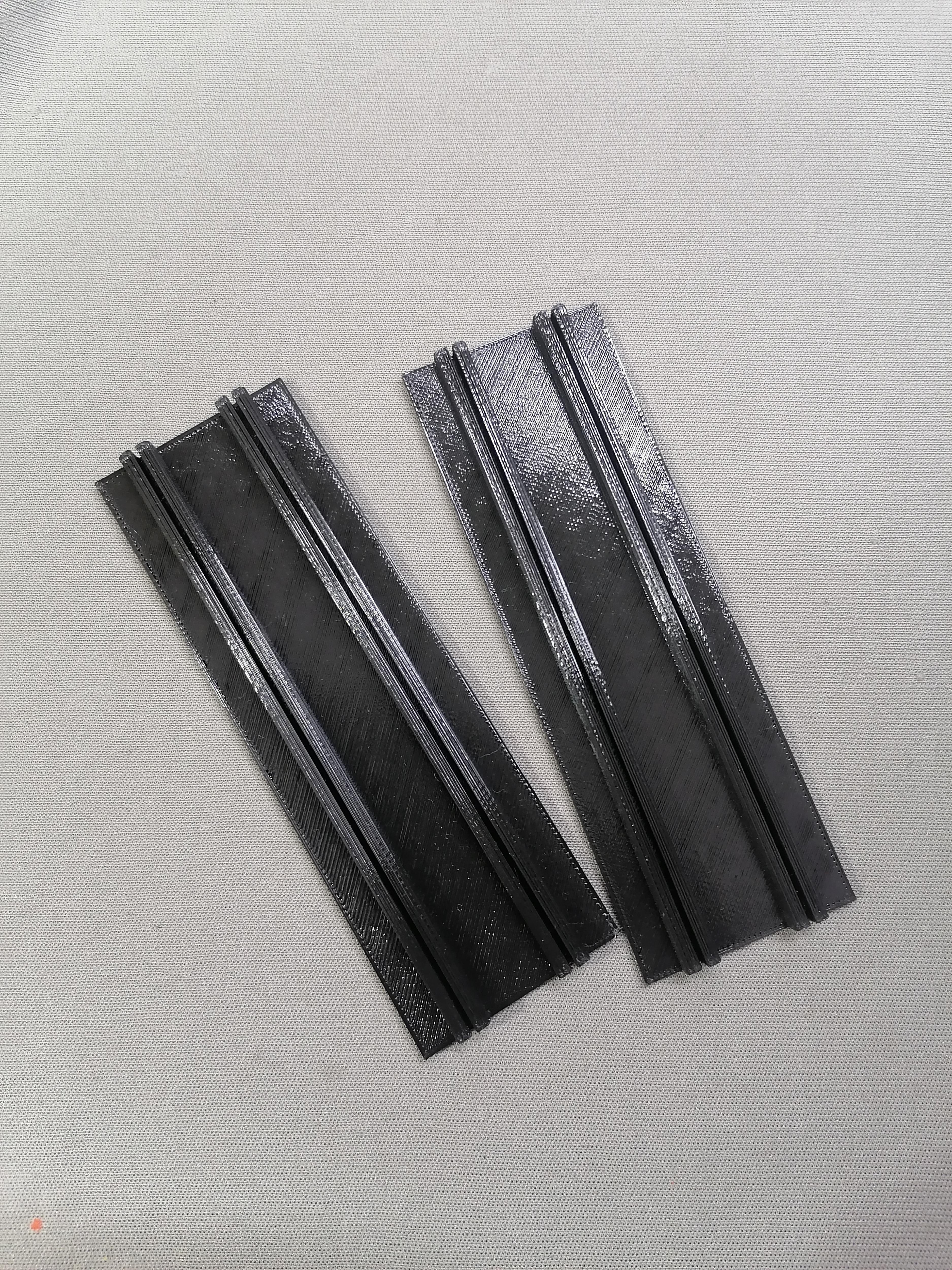
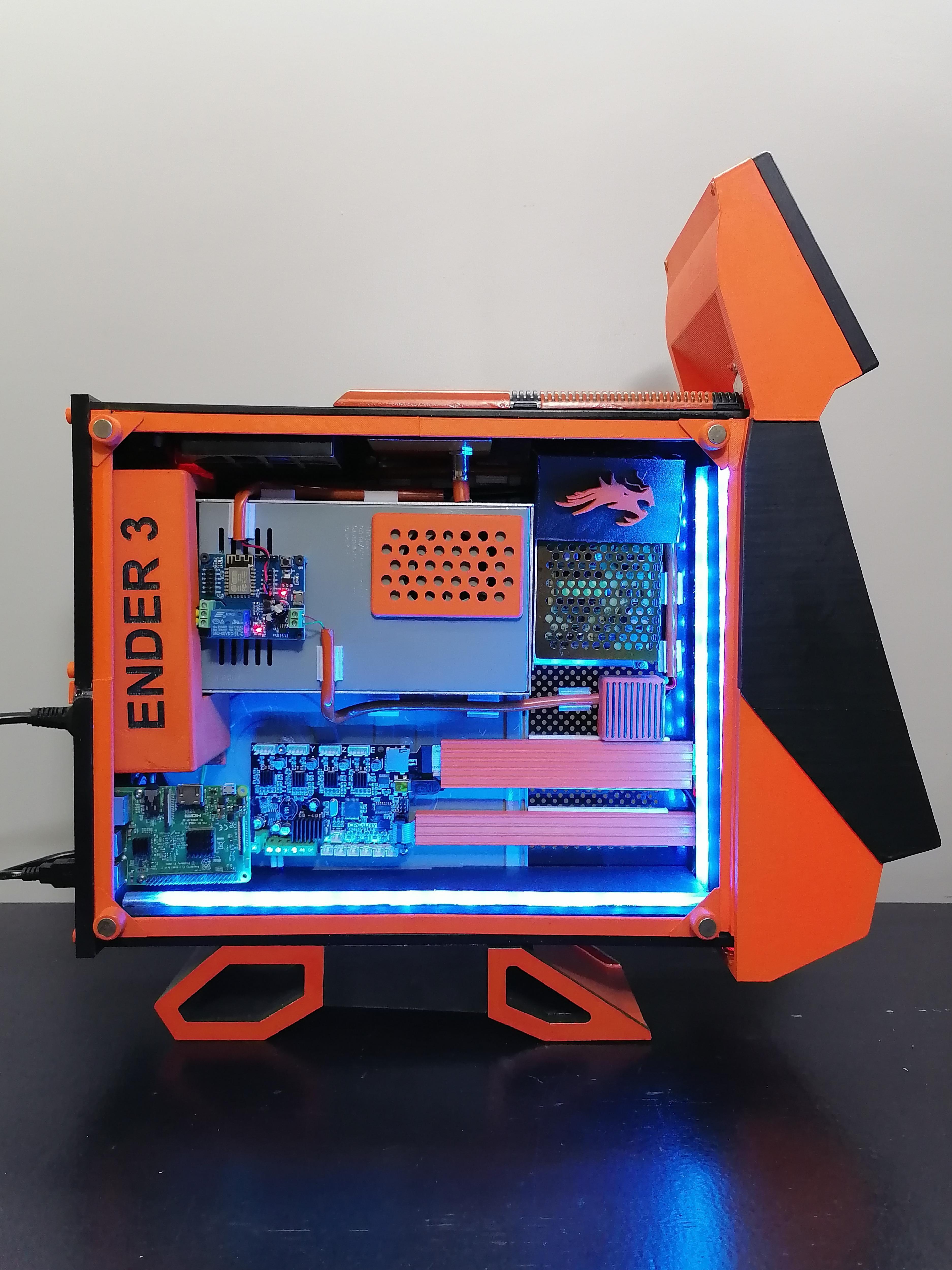
Attaching the LED Strip on Both LED Plate and Inside of Front Part
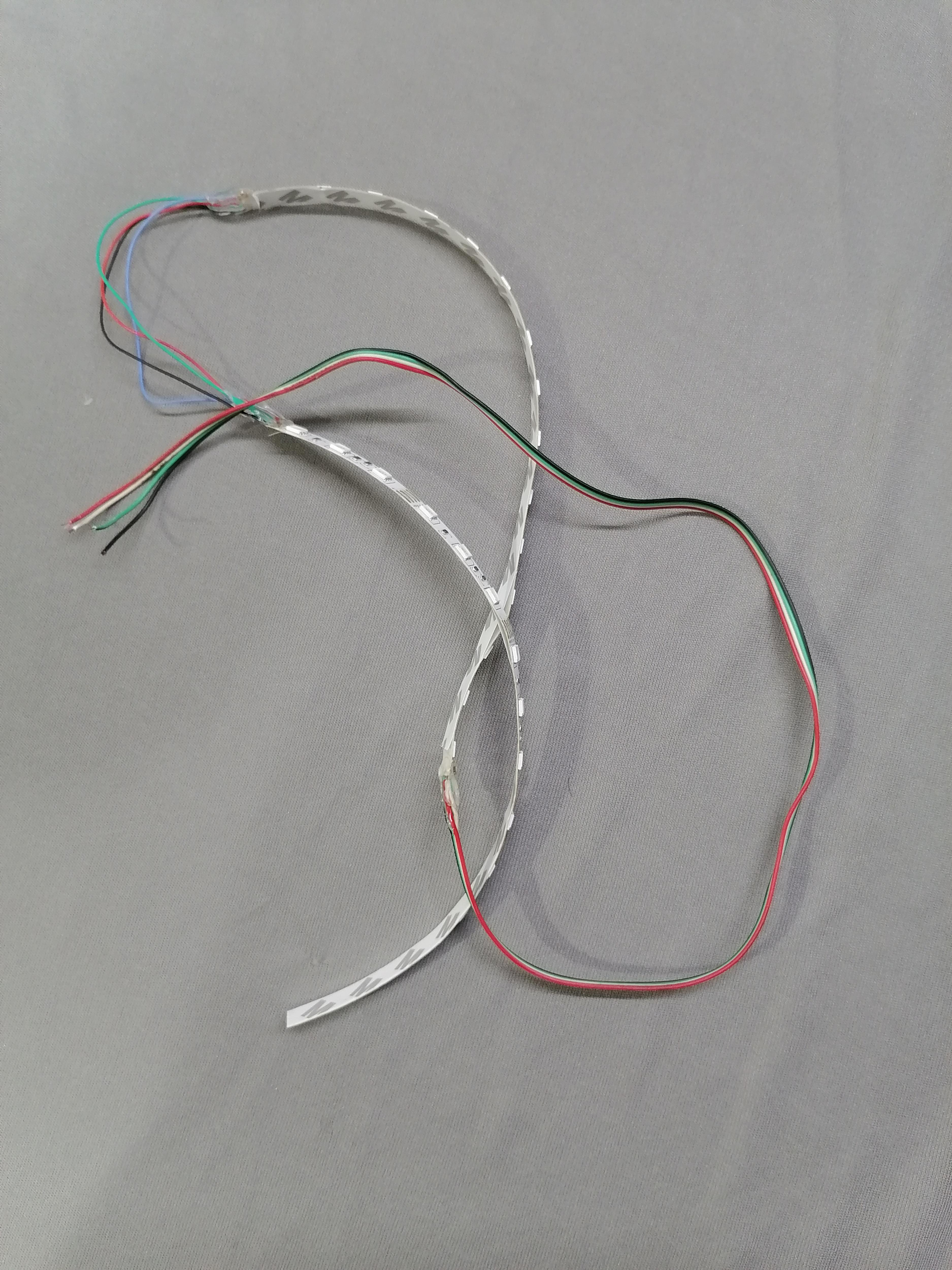
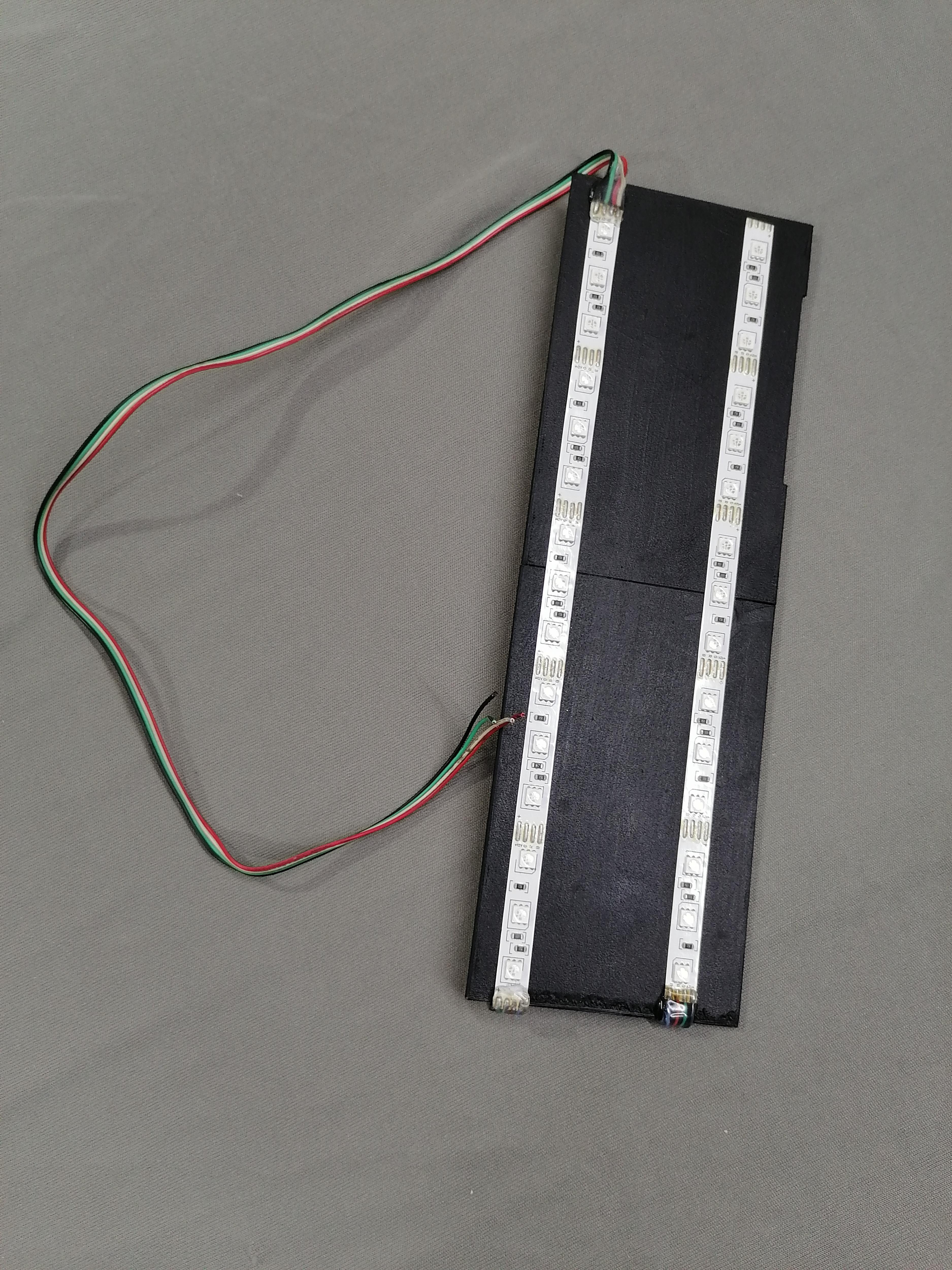
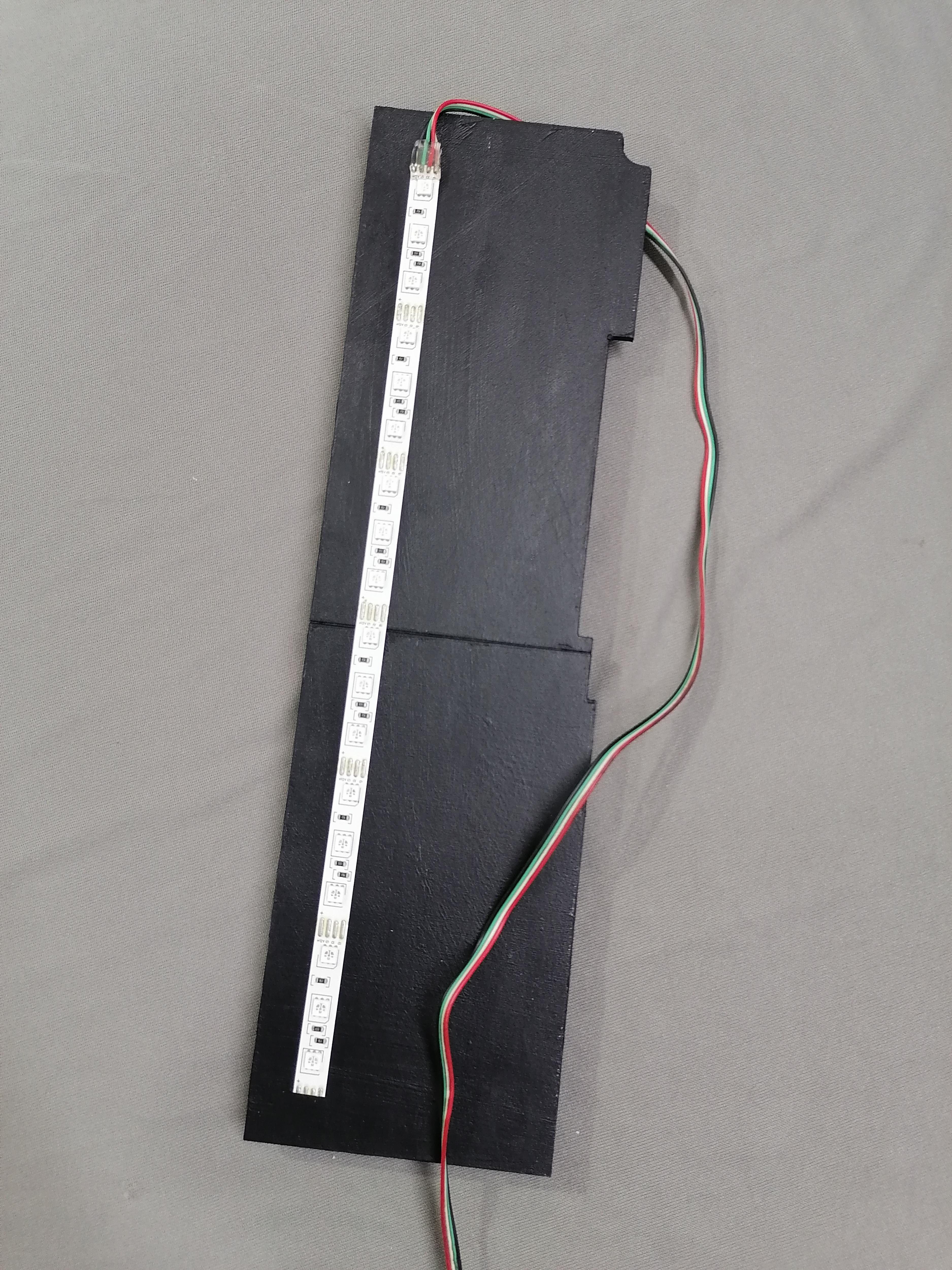
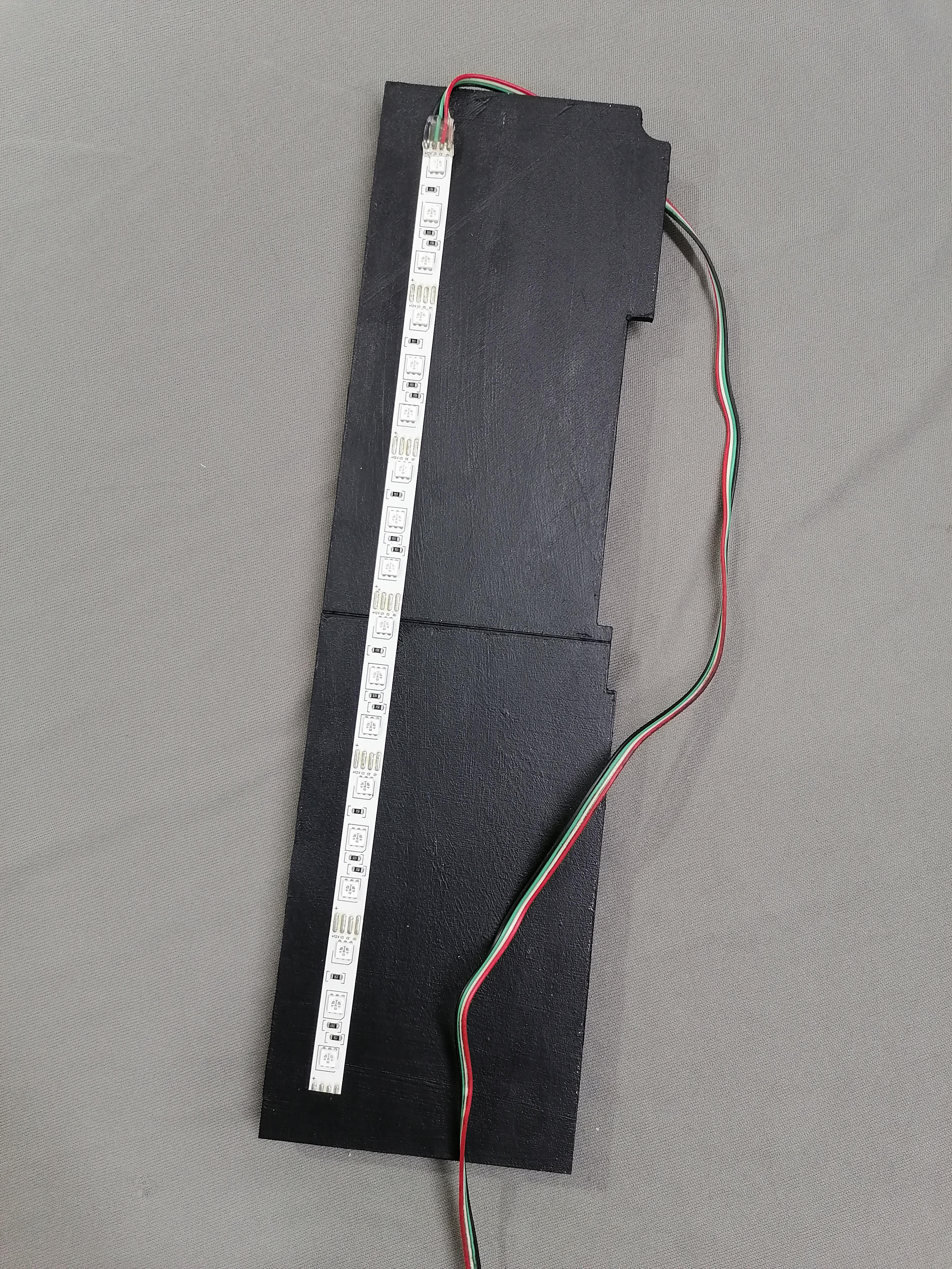
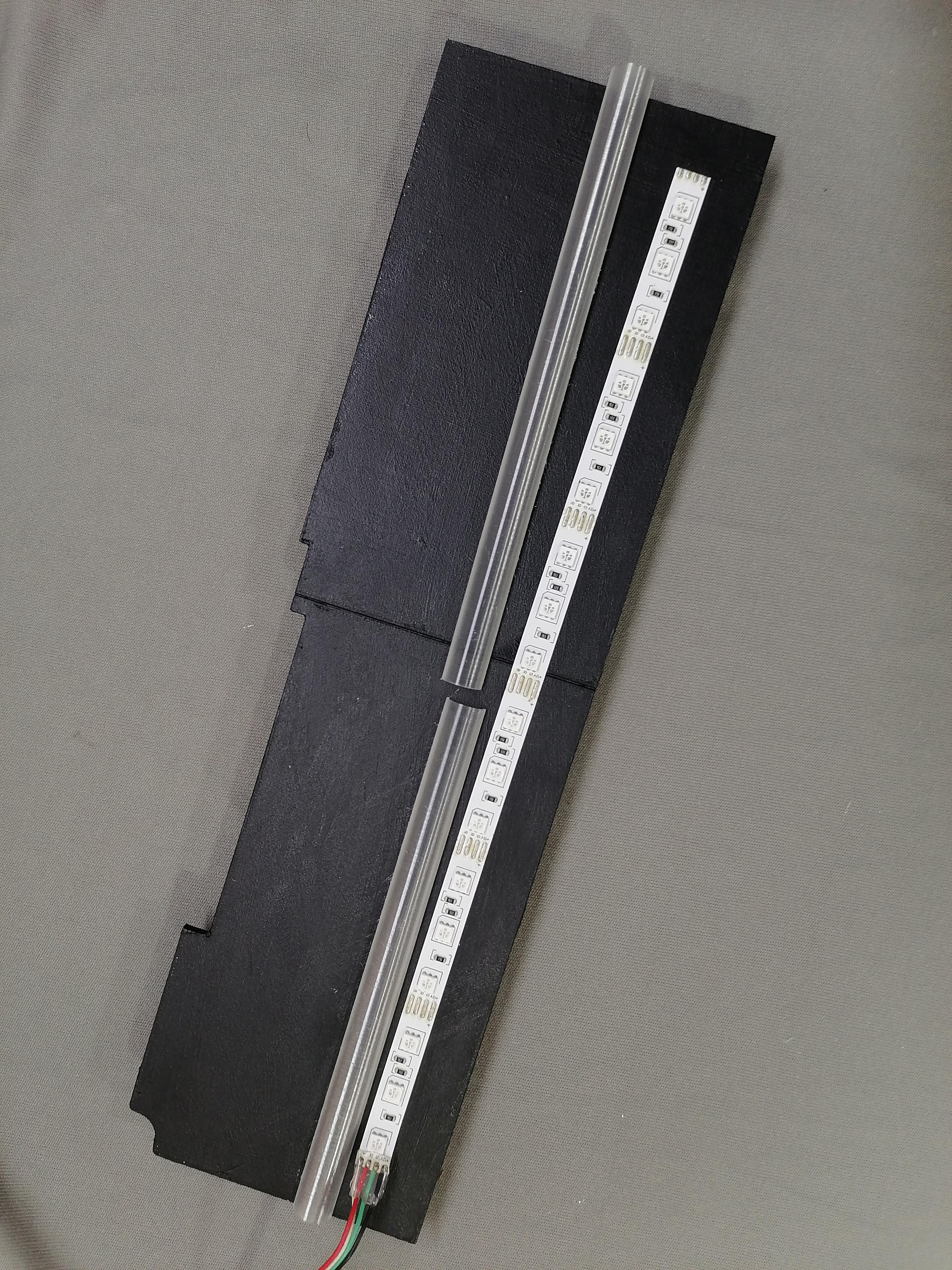
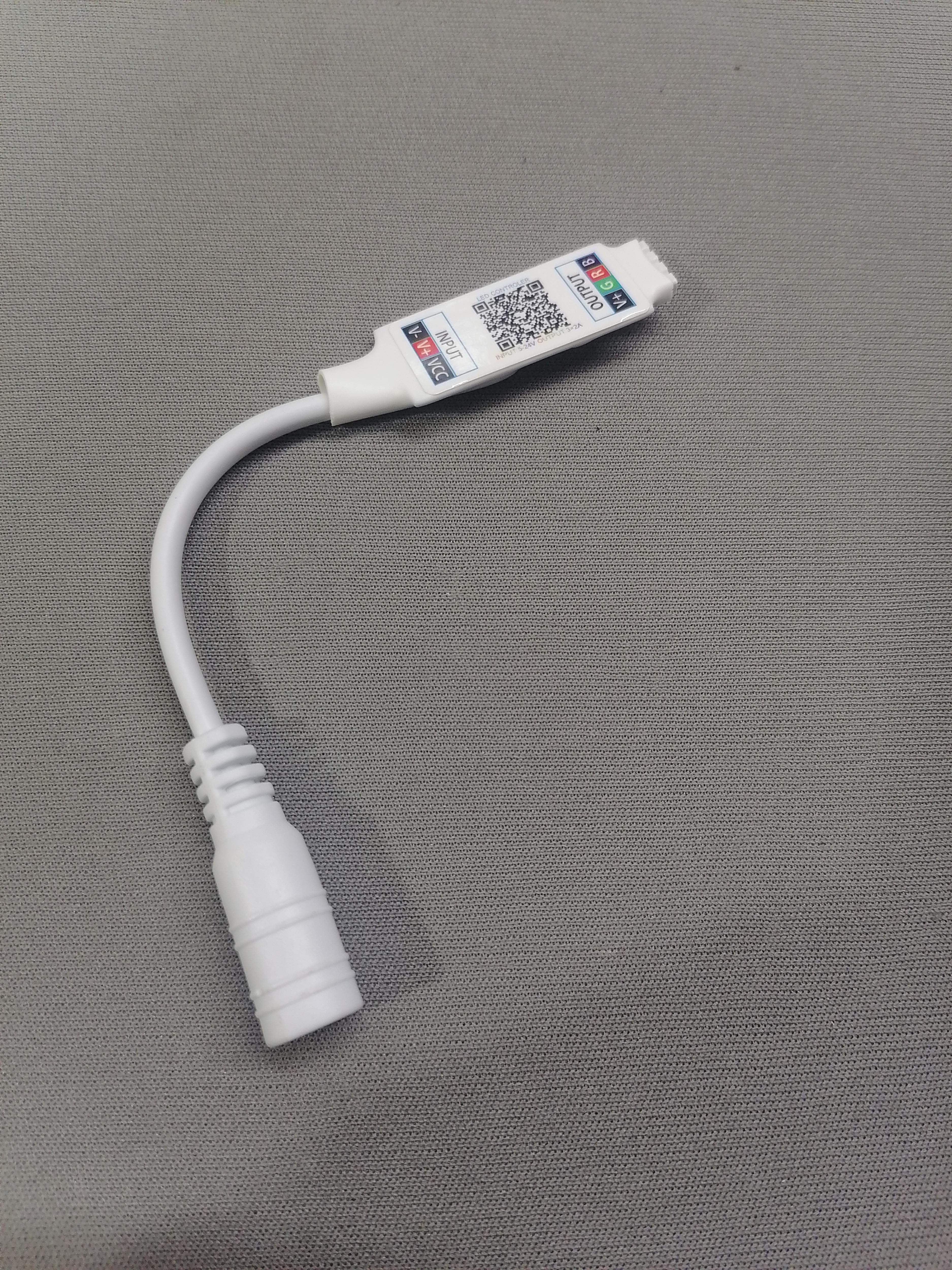
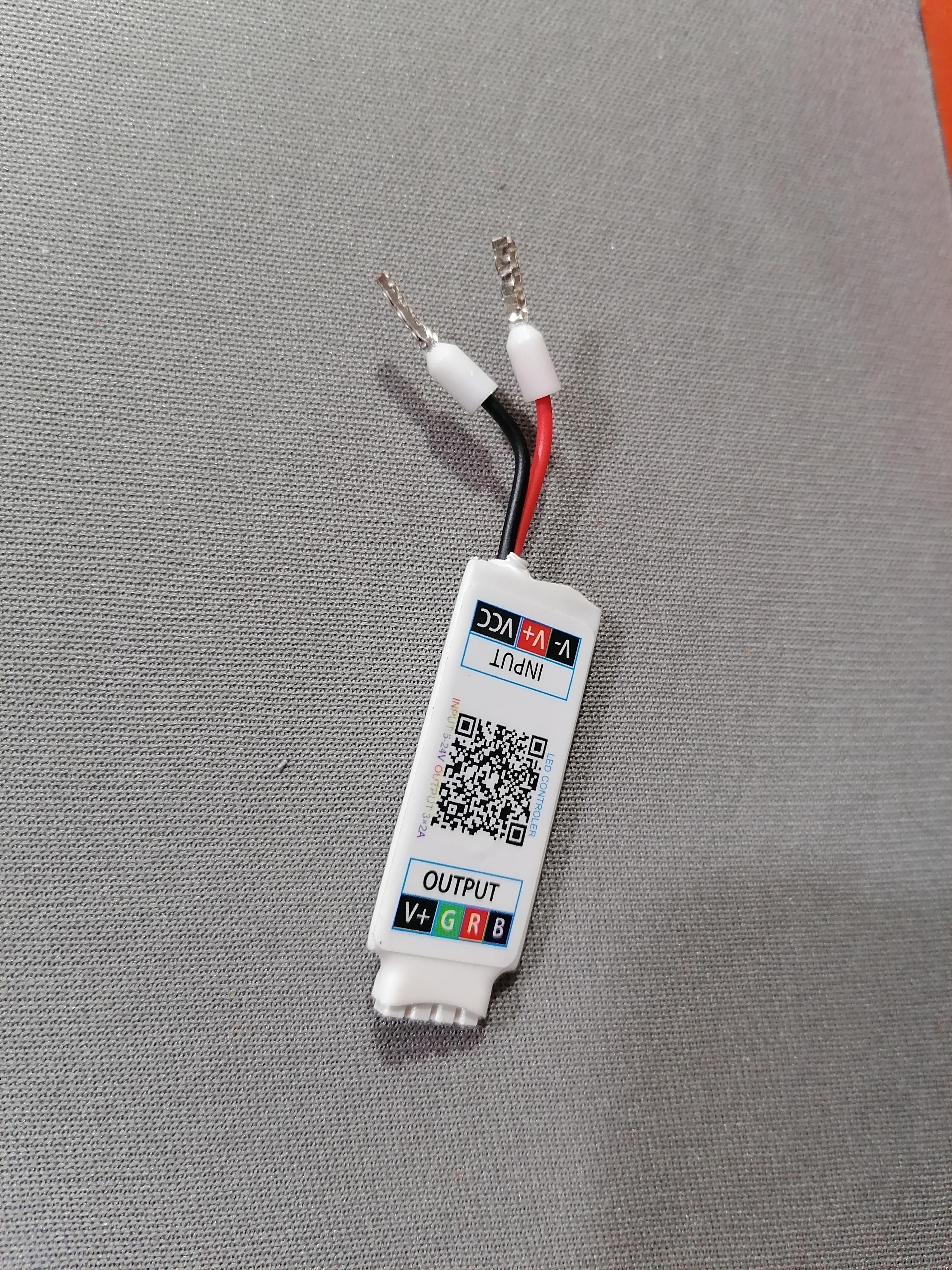
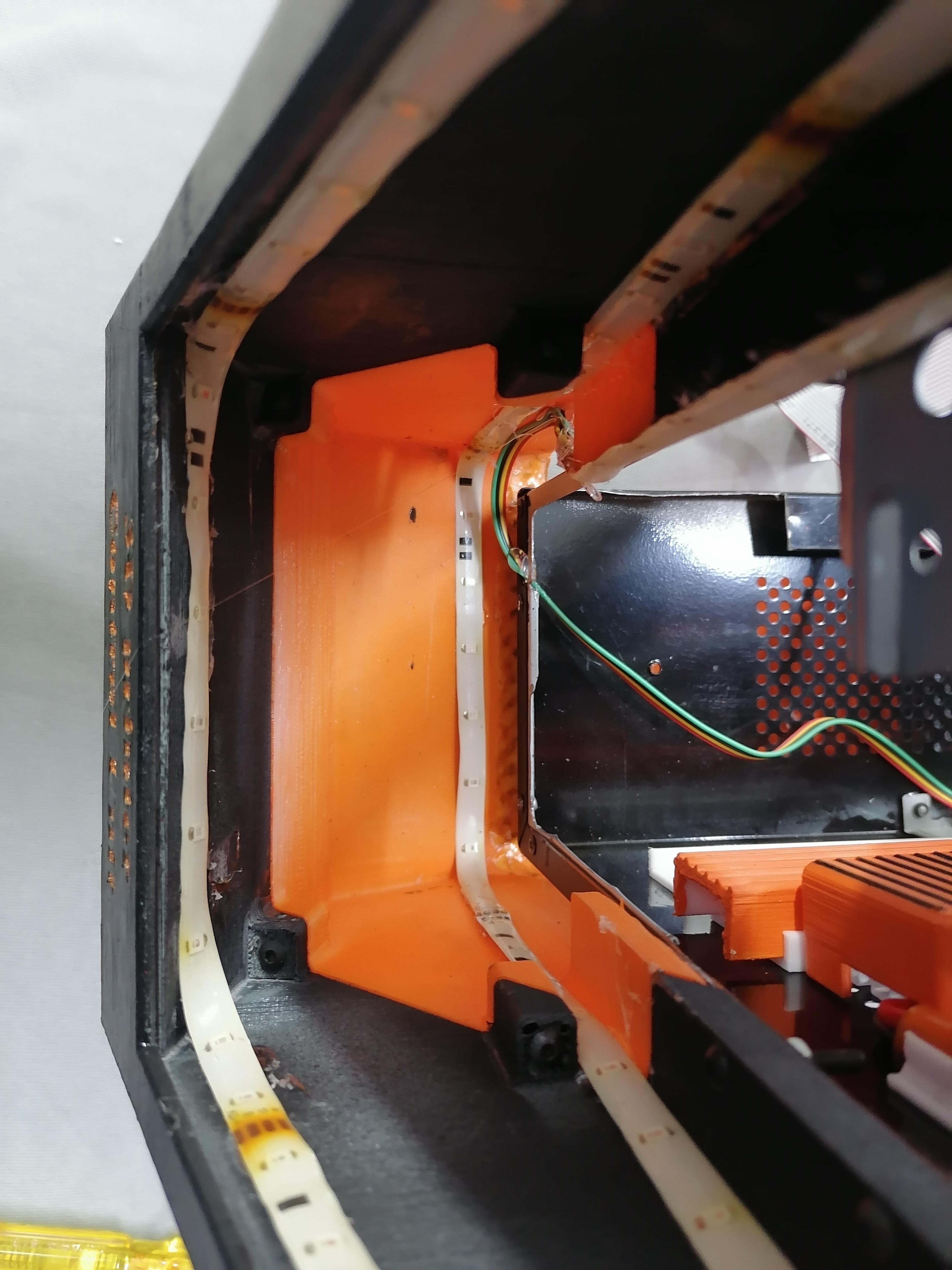
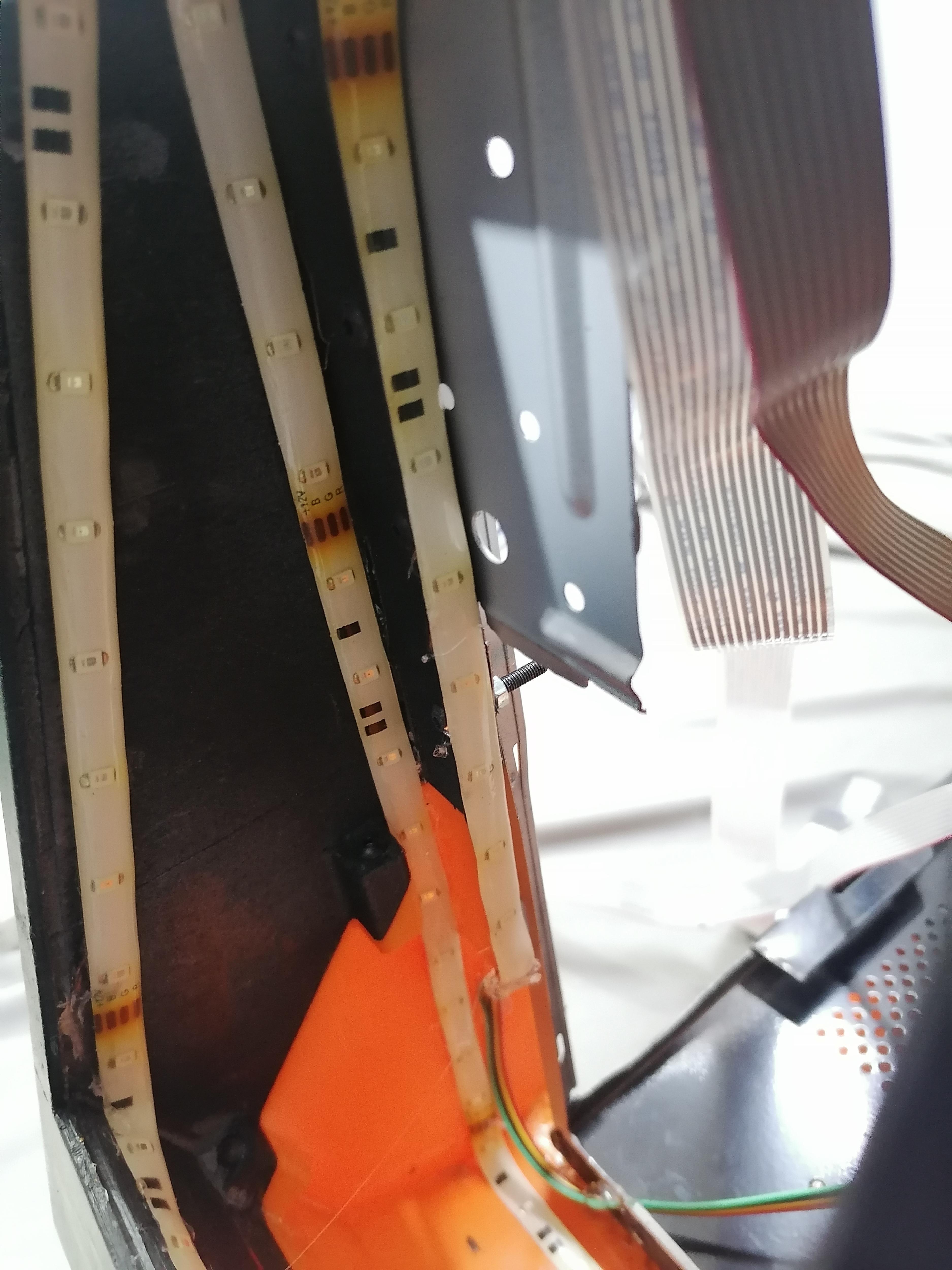
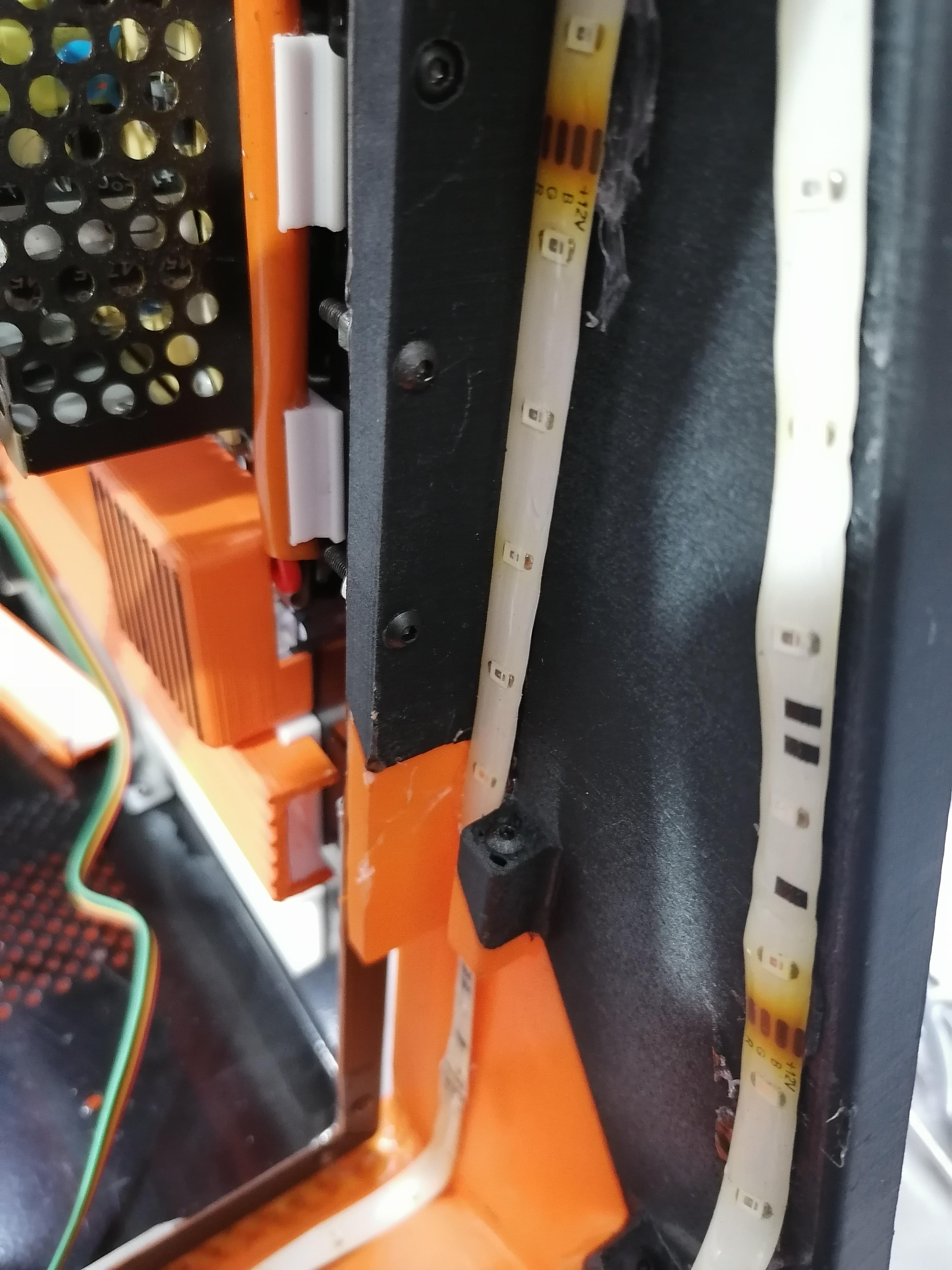
Use RGB LED Strip 12v with Bluetooth controller. Stick the LED strip on LED plates both Bottom and Side and also inside the front compartment. Complete the wiring of LED strips
Note: Refer image for more understanding.
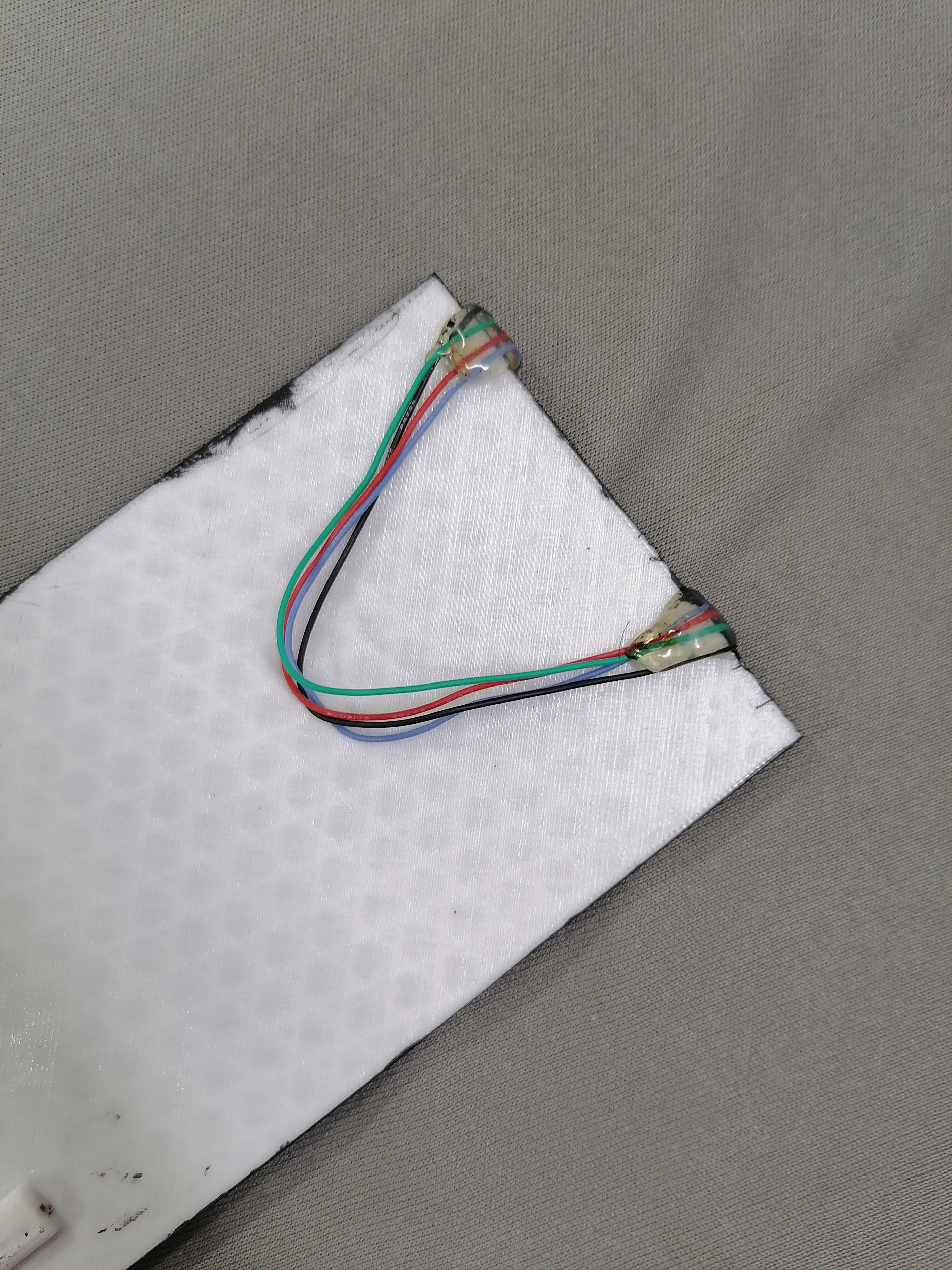
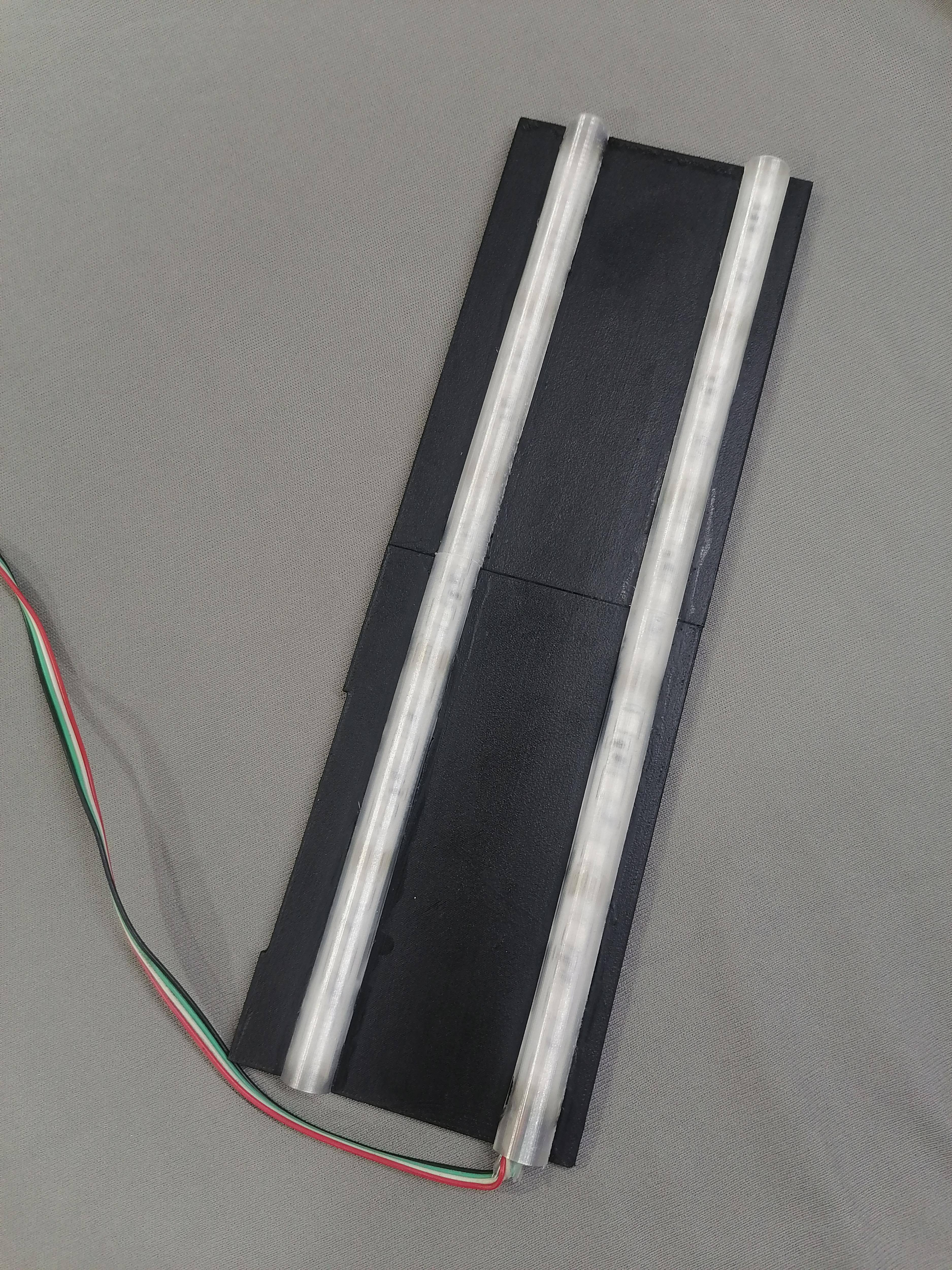
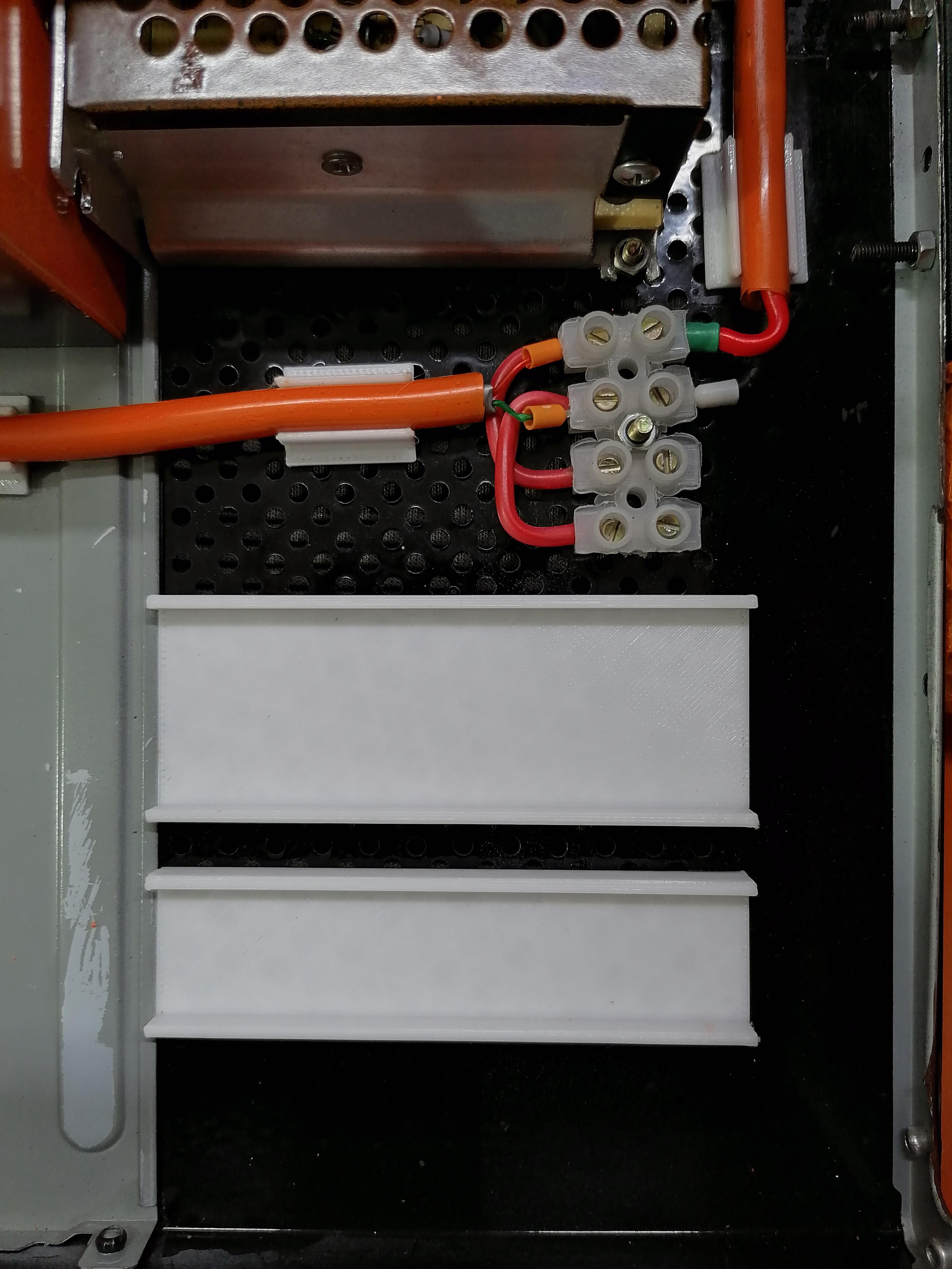
Wiring the LED Strips

Wire Harness the LED strips to controller and to Power Supply.
Hide all wire under the plate as shown in image.
Note: Refer image for more understanding.
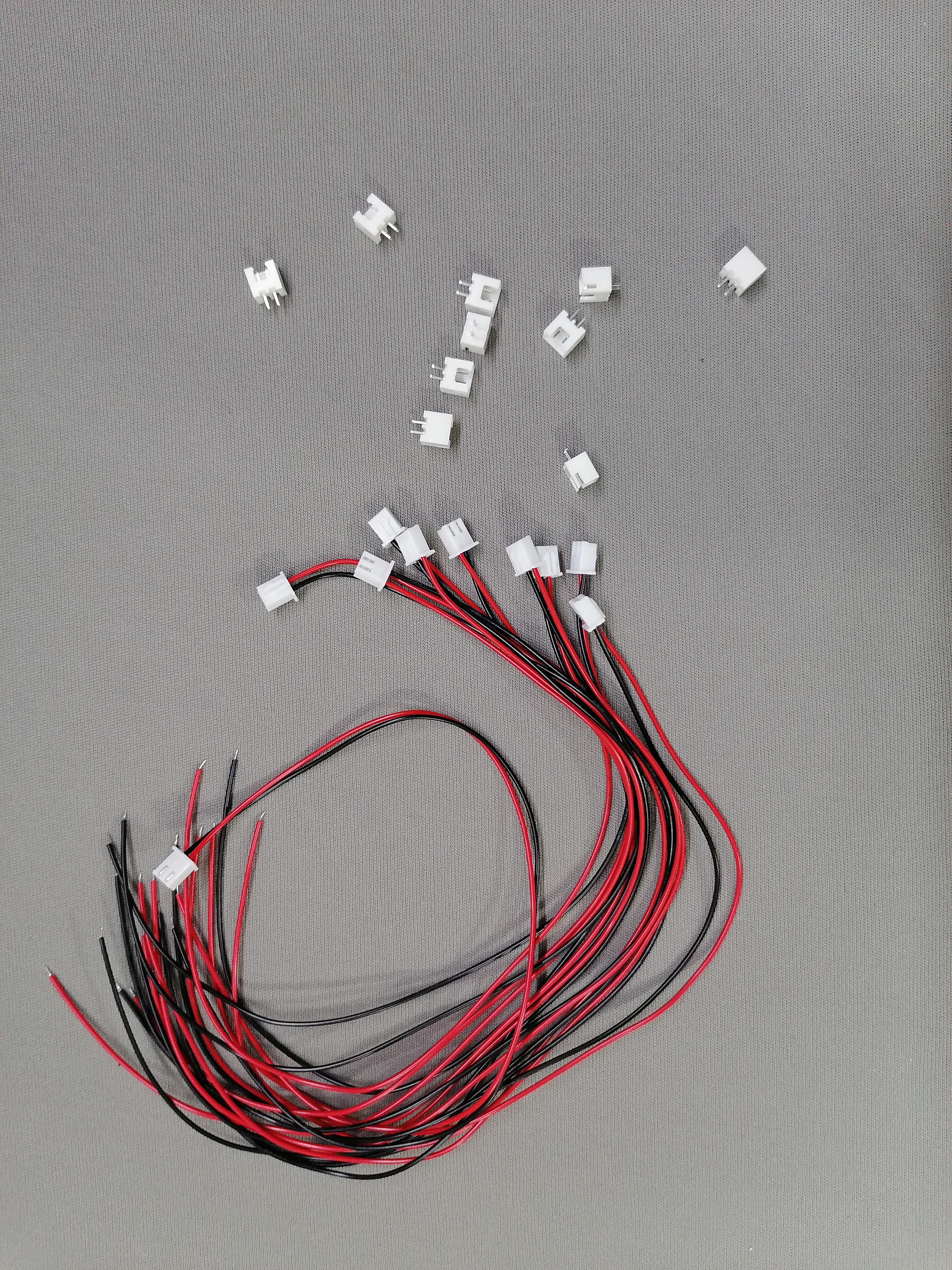
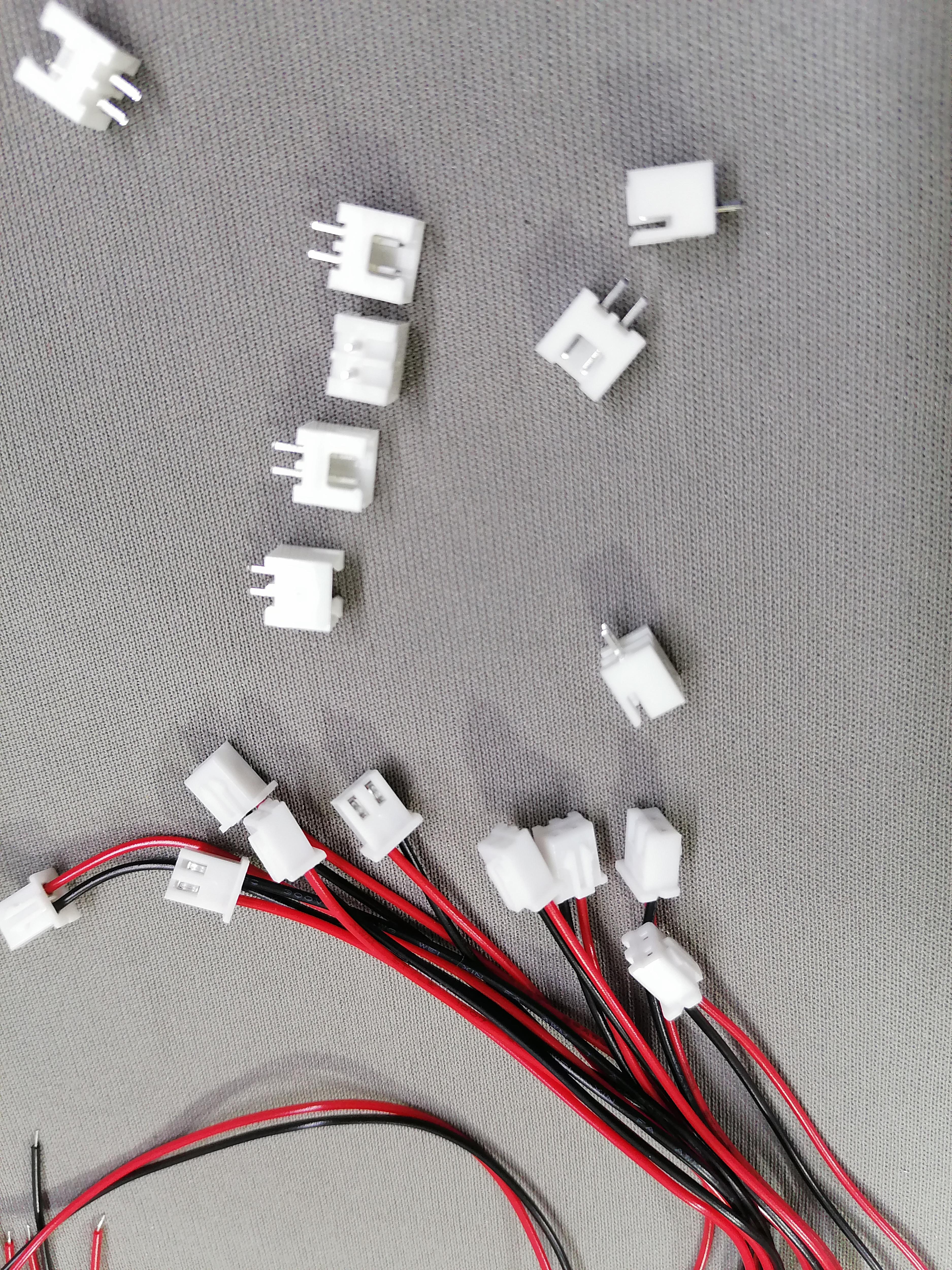
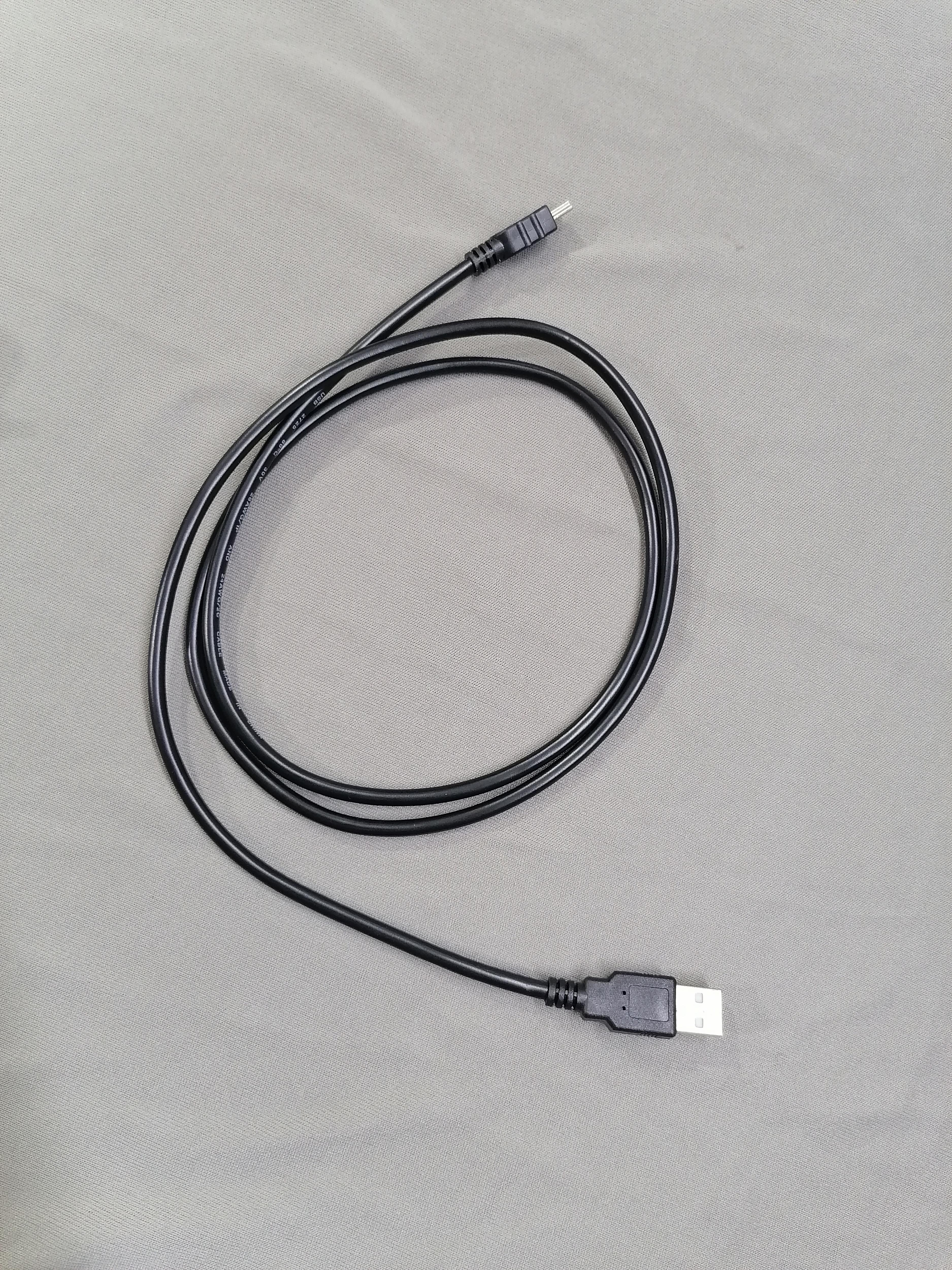
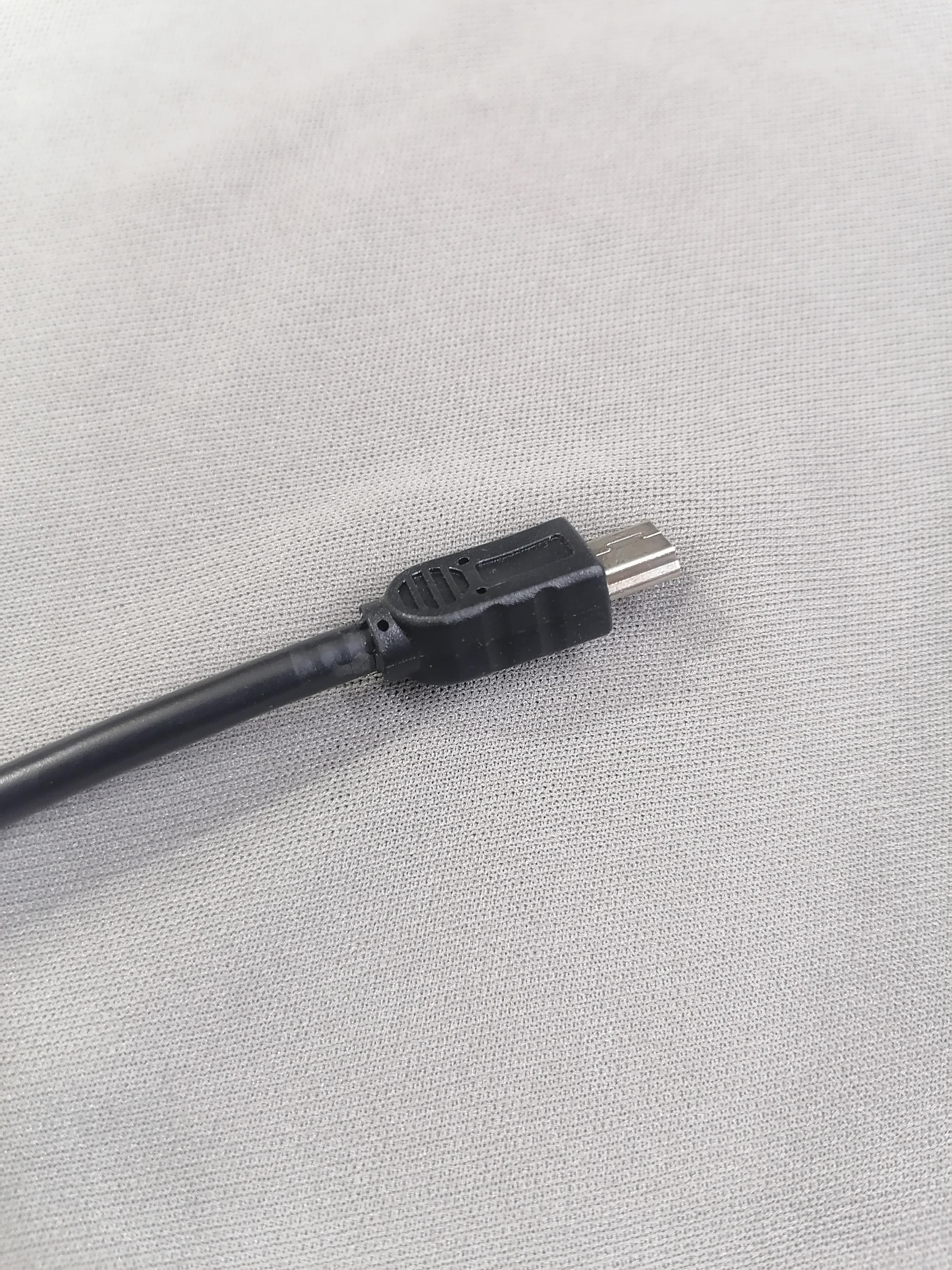
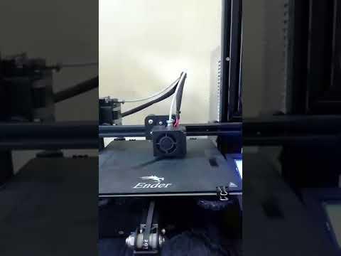
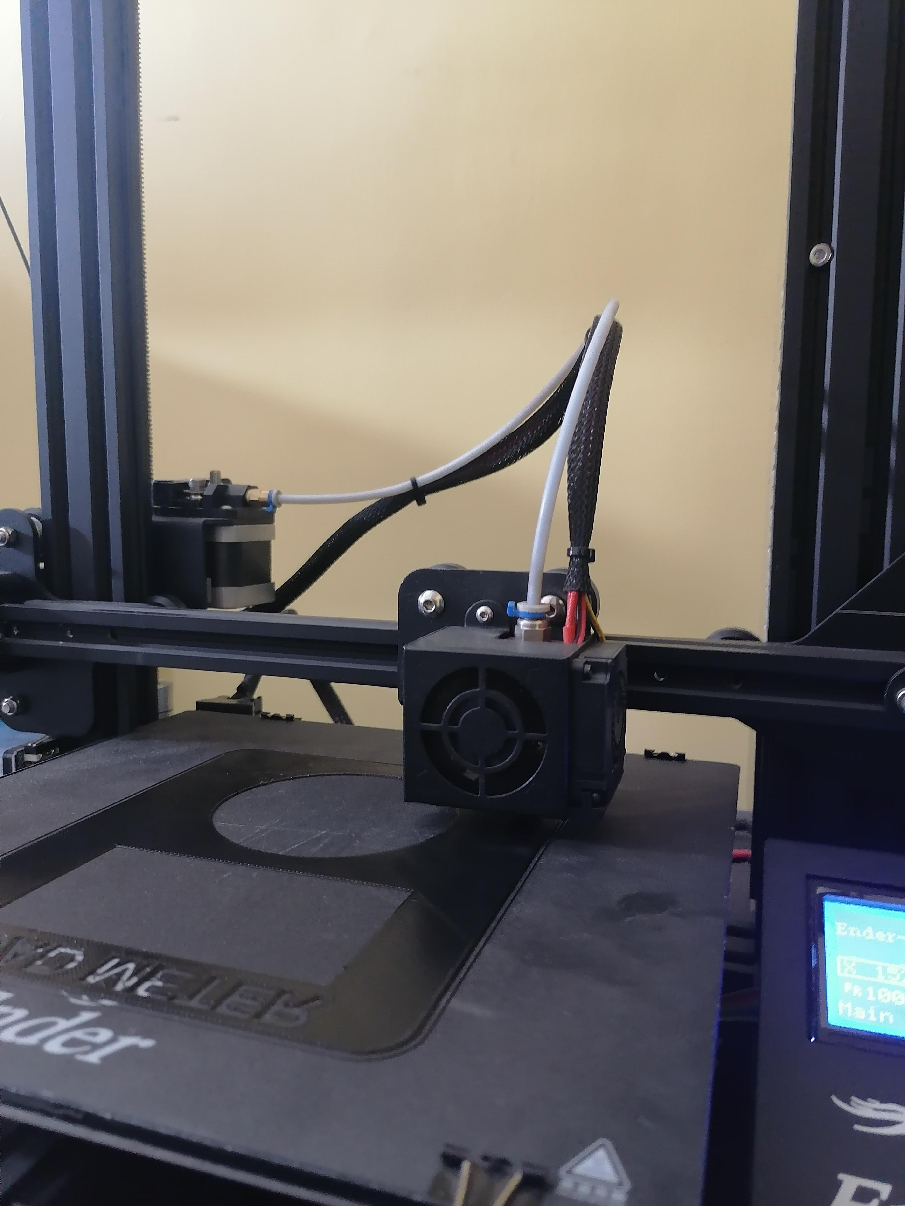
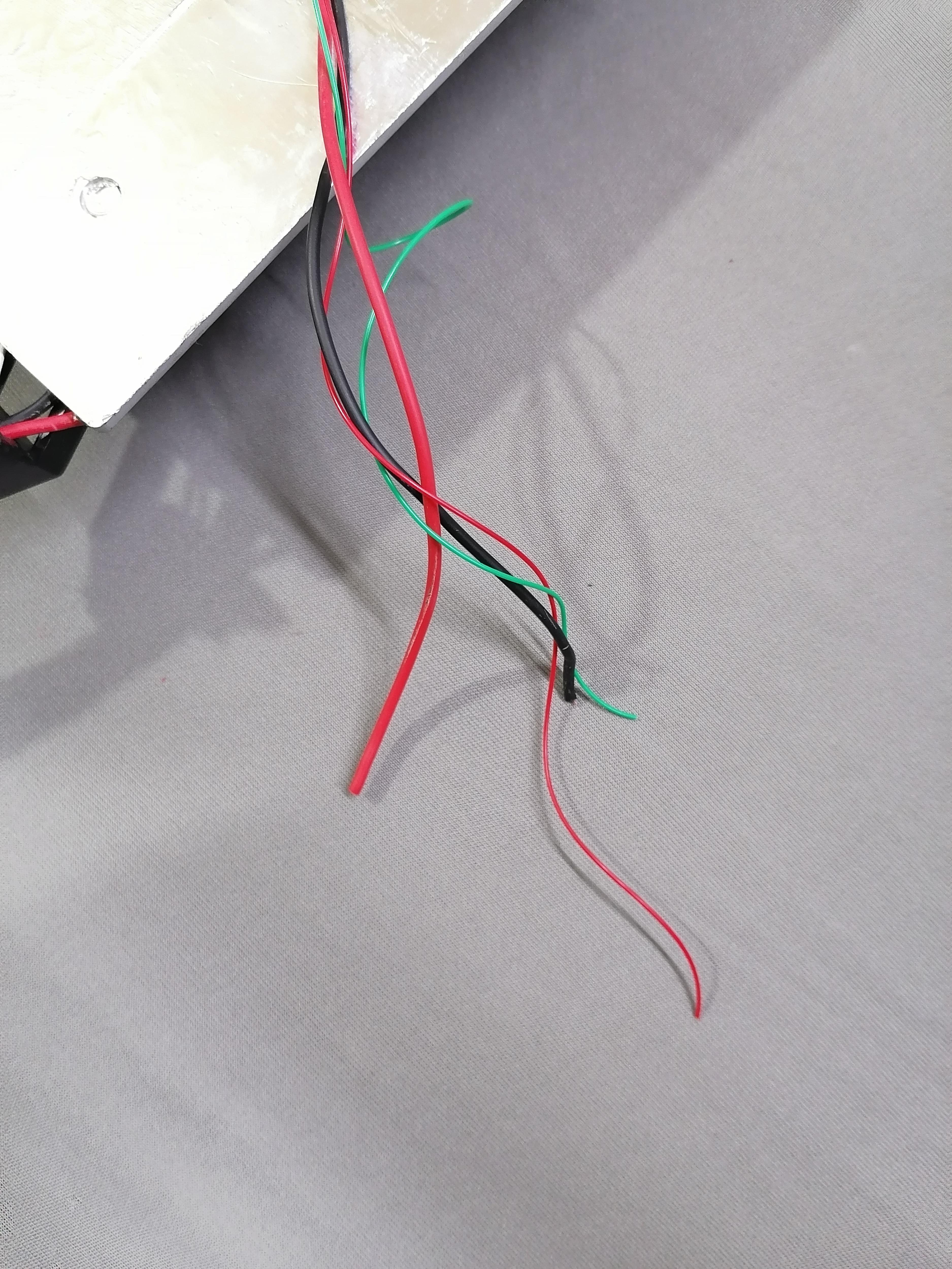
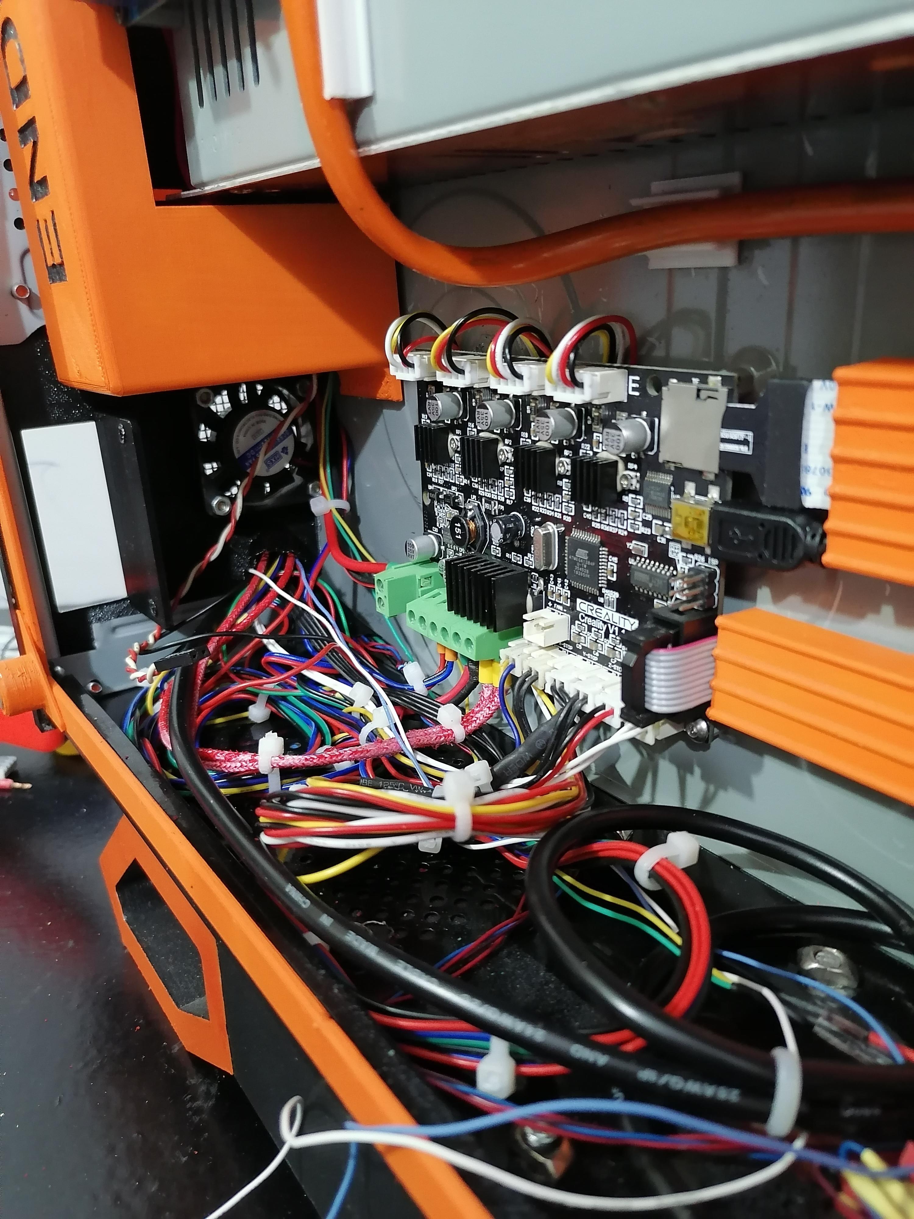
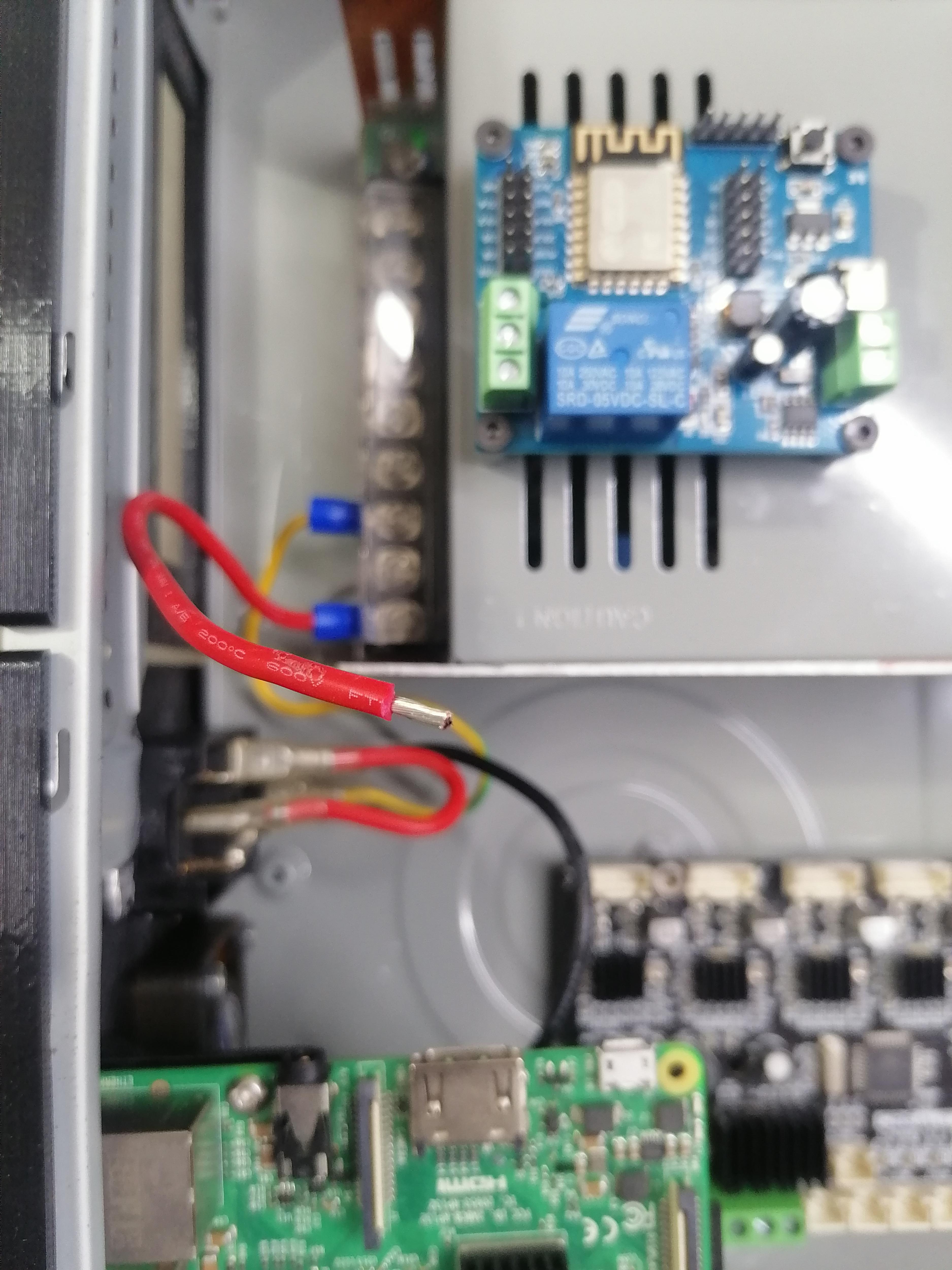
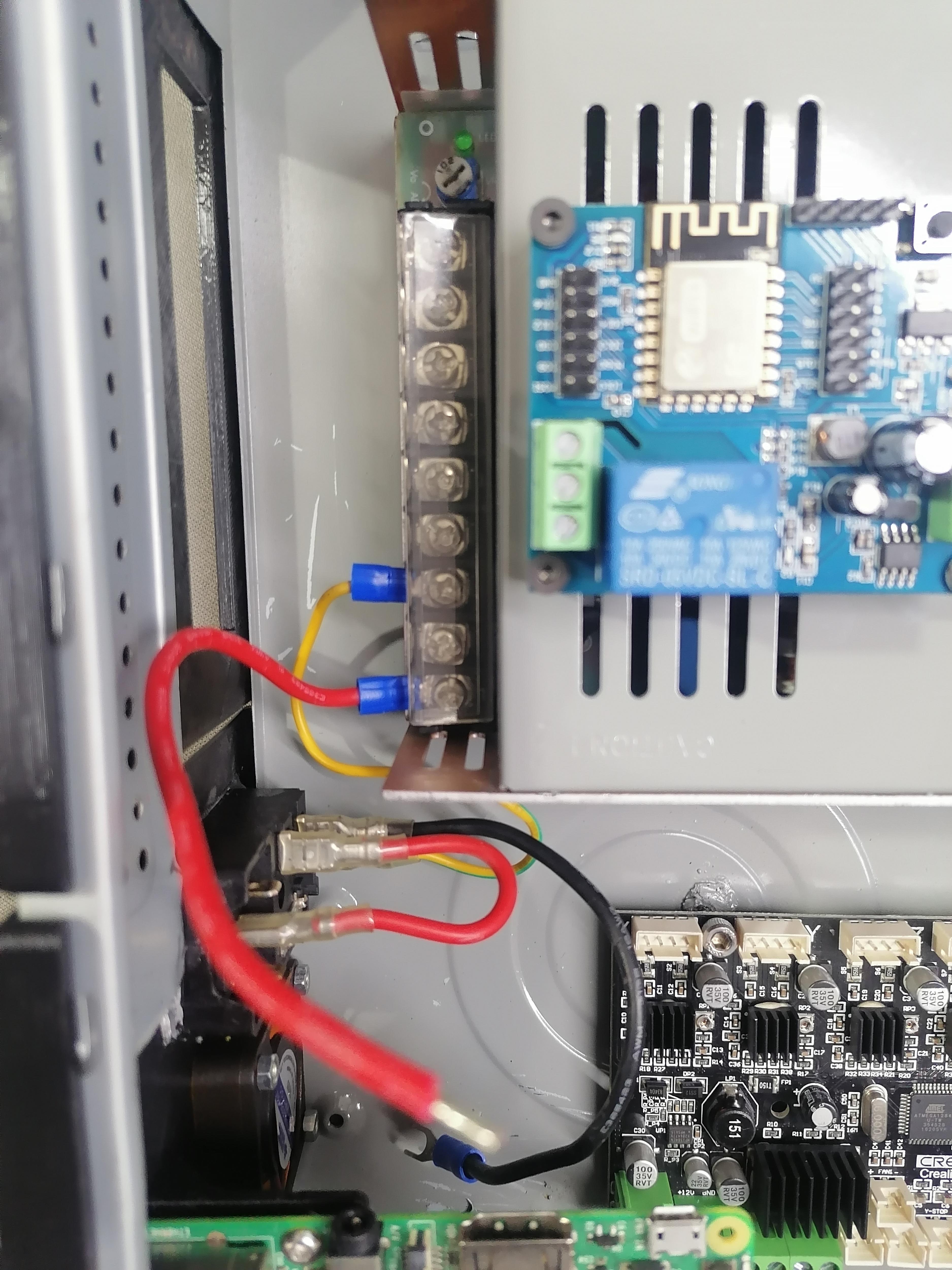
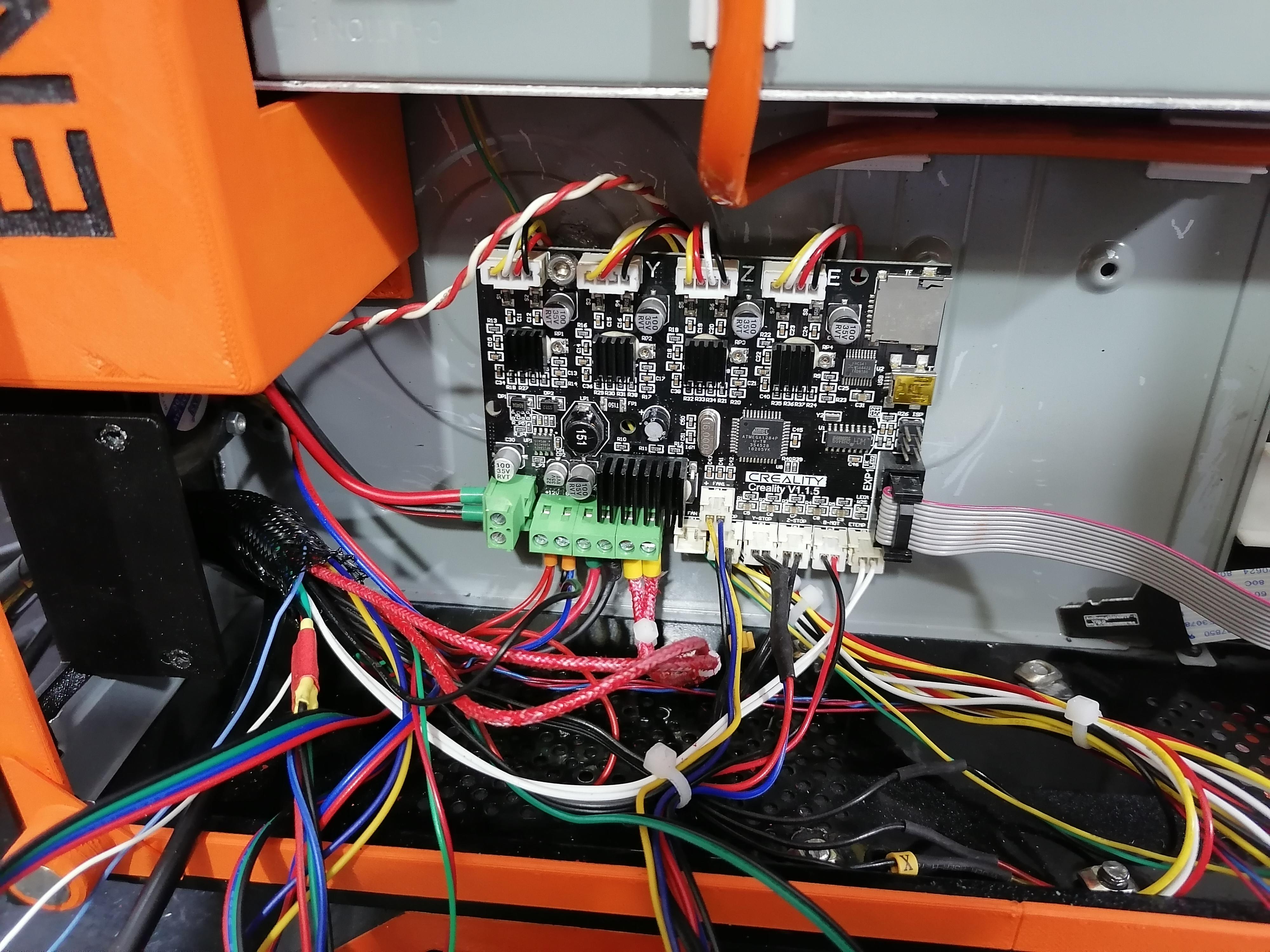
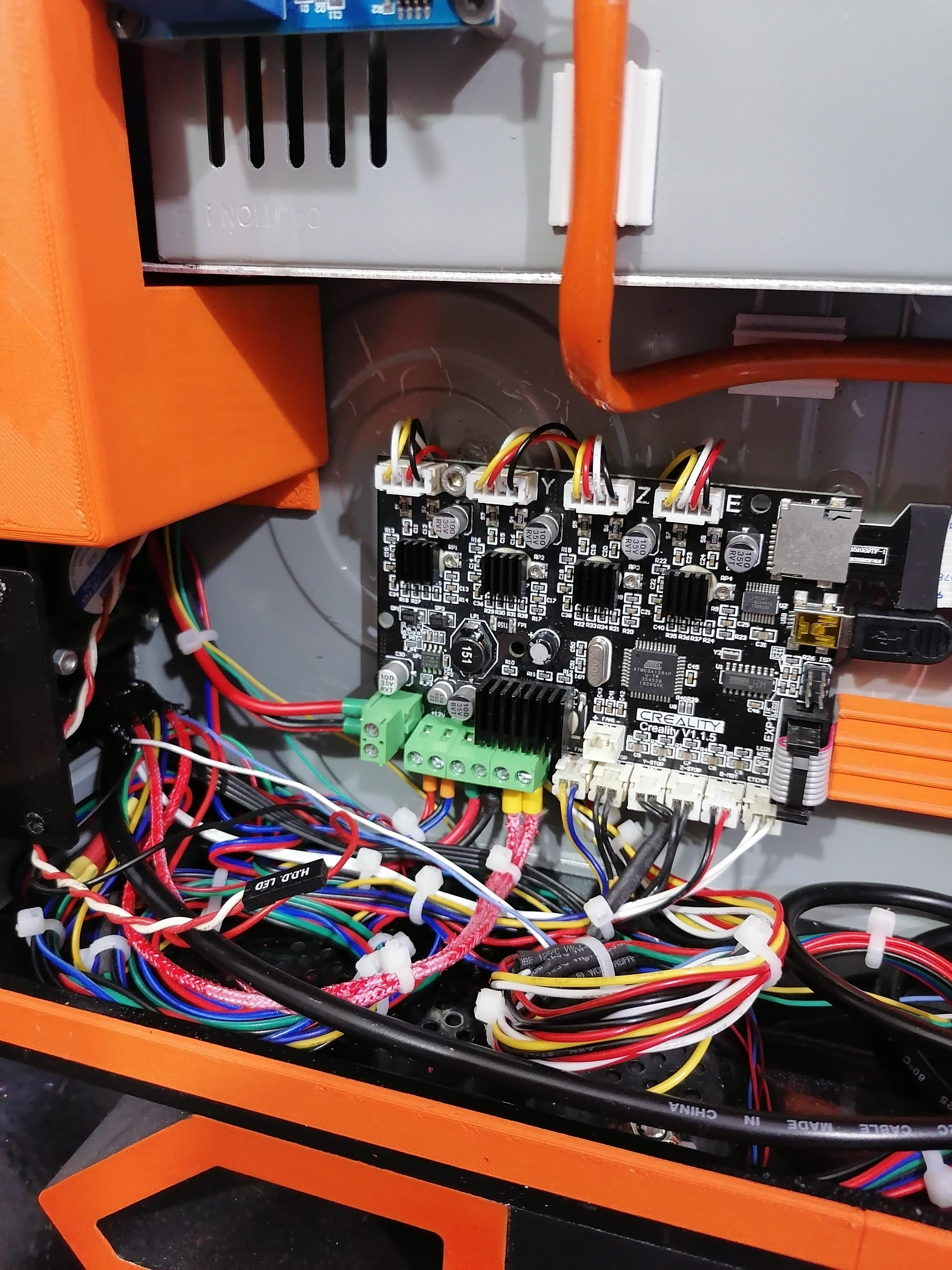
Extend All Wires of 3D Printers
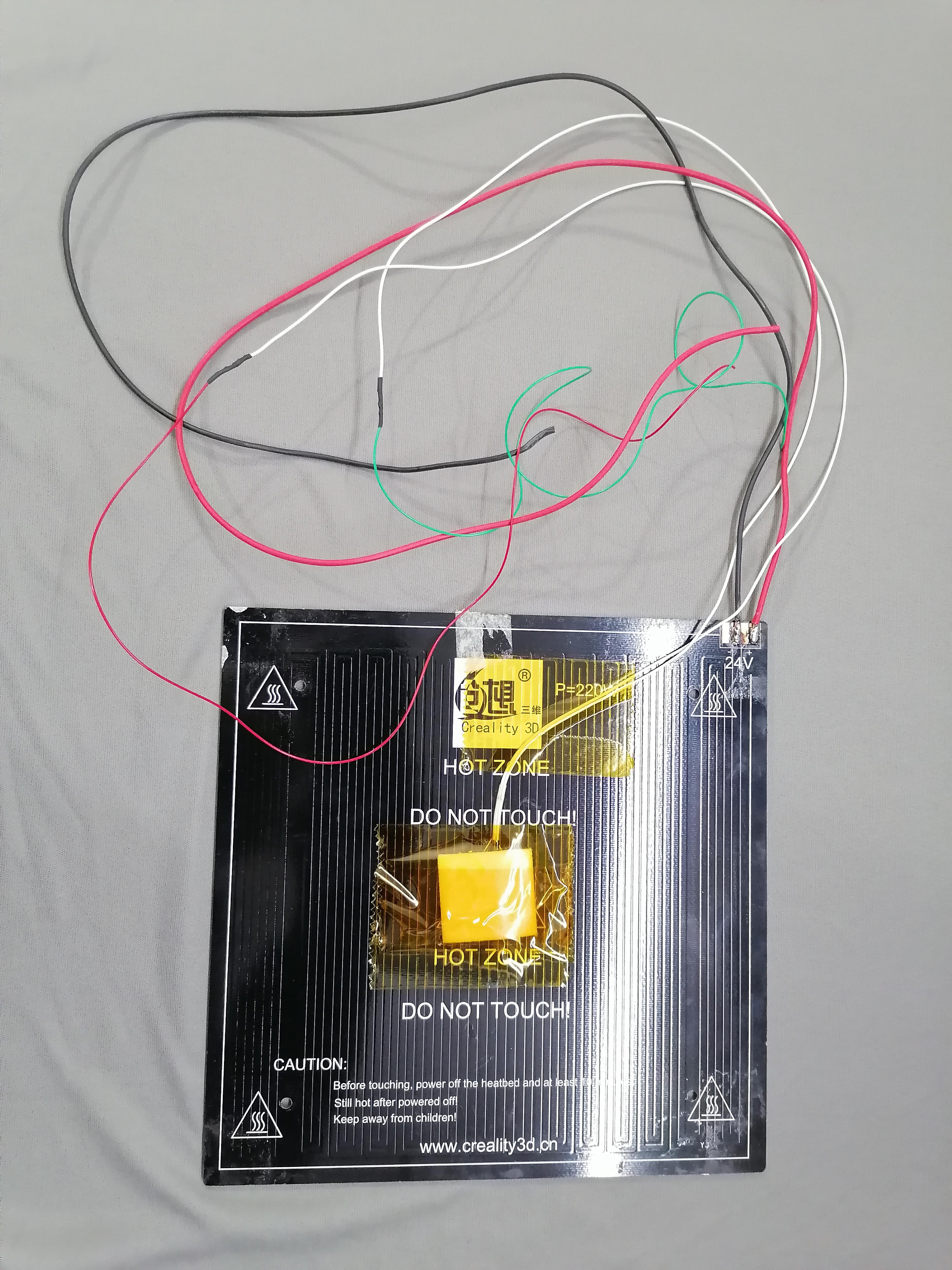
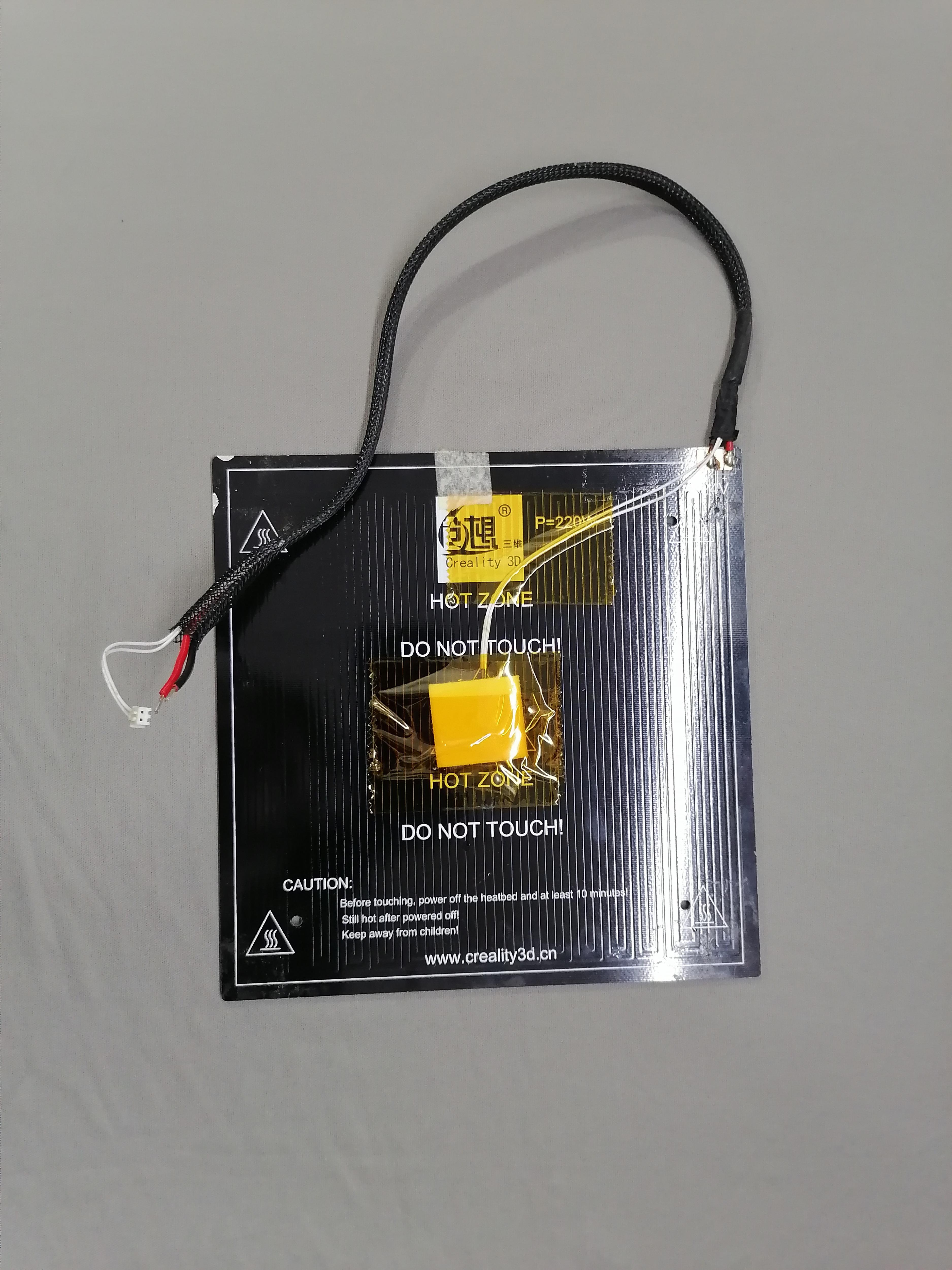
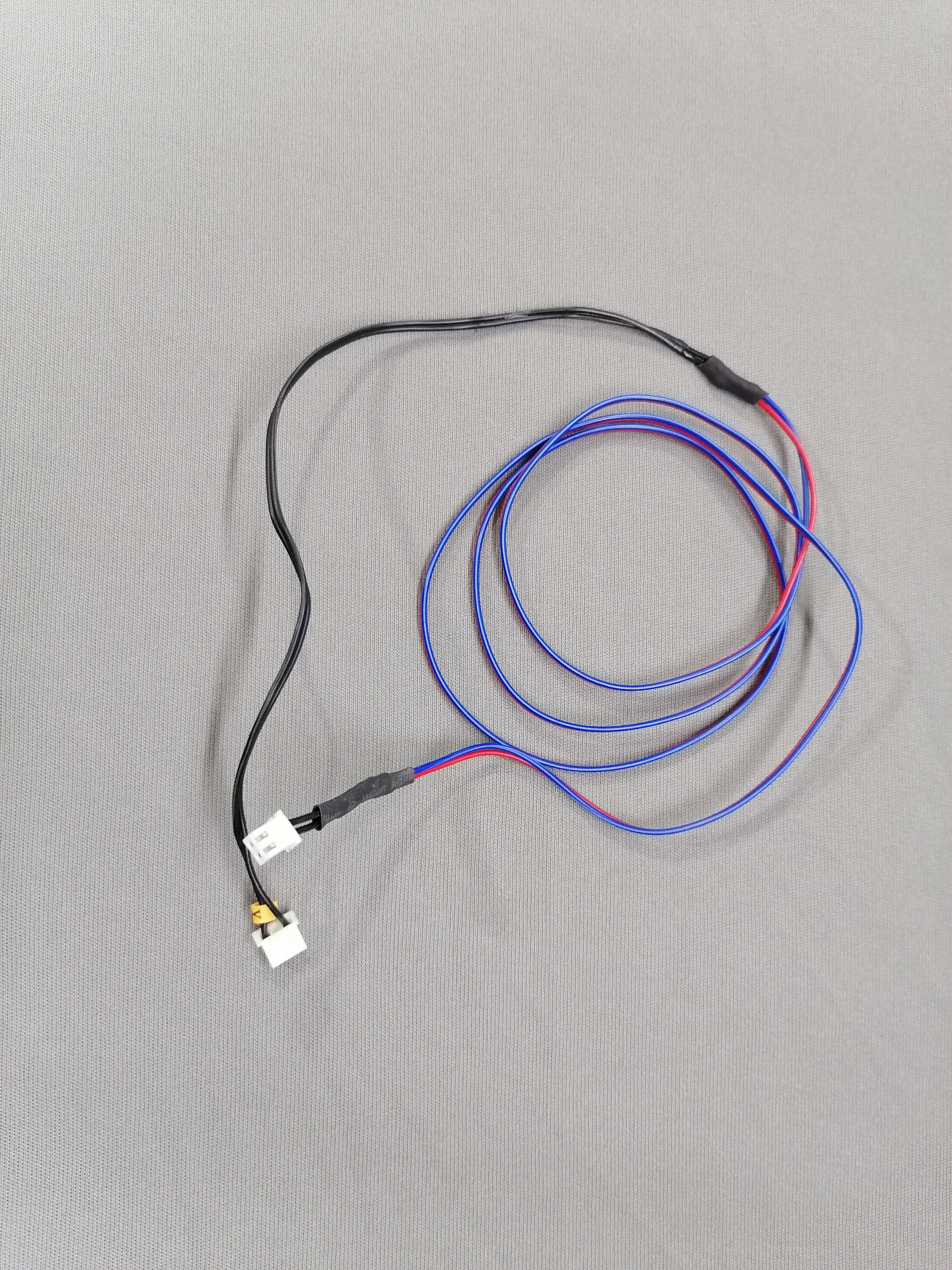
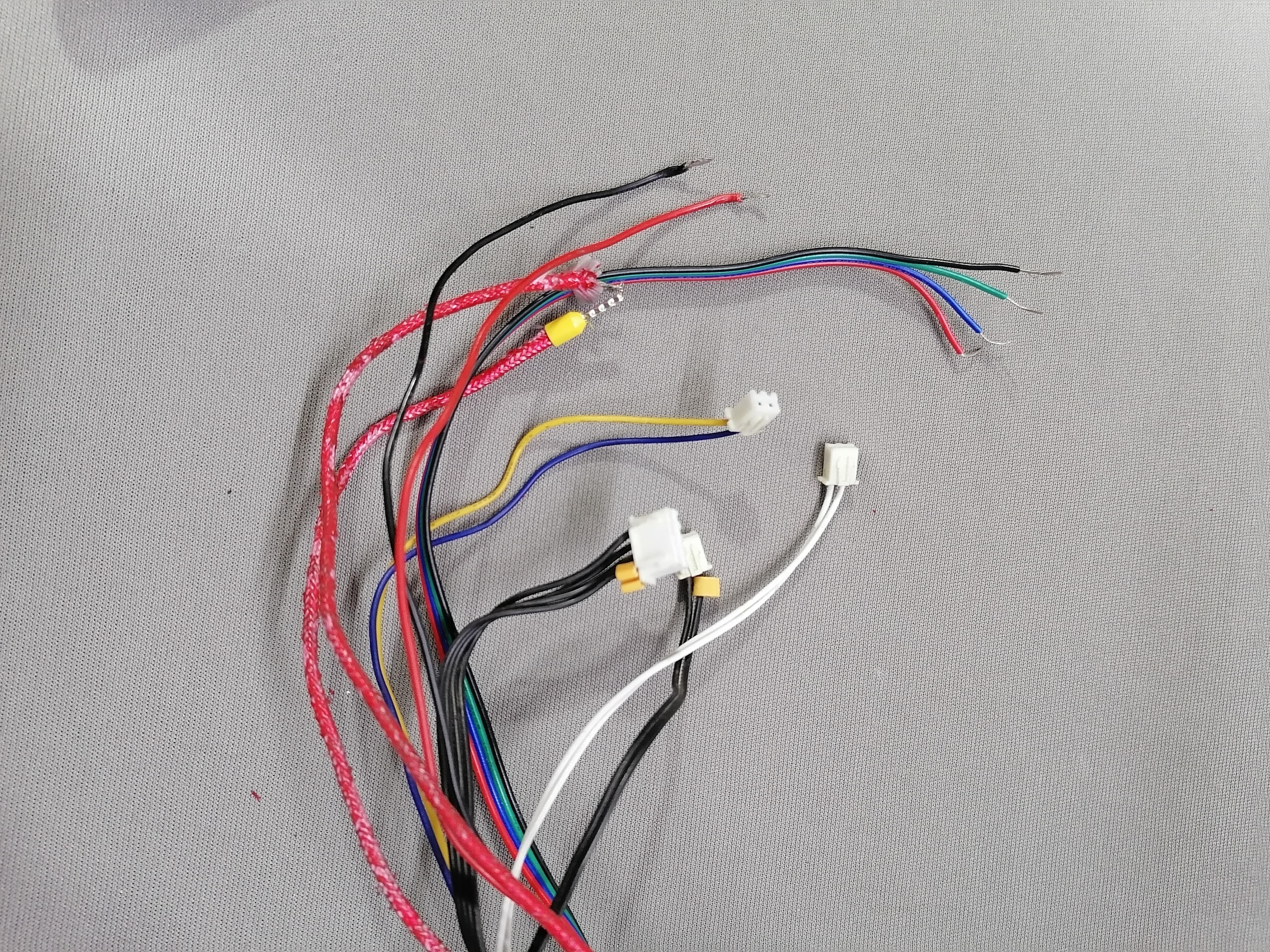
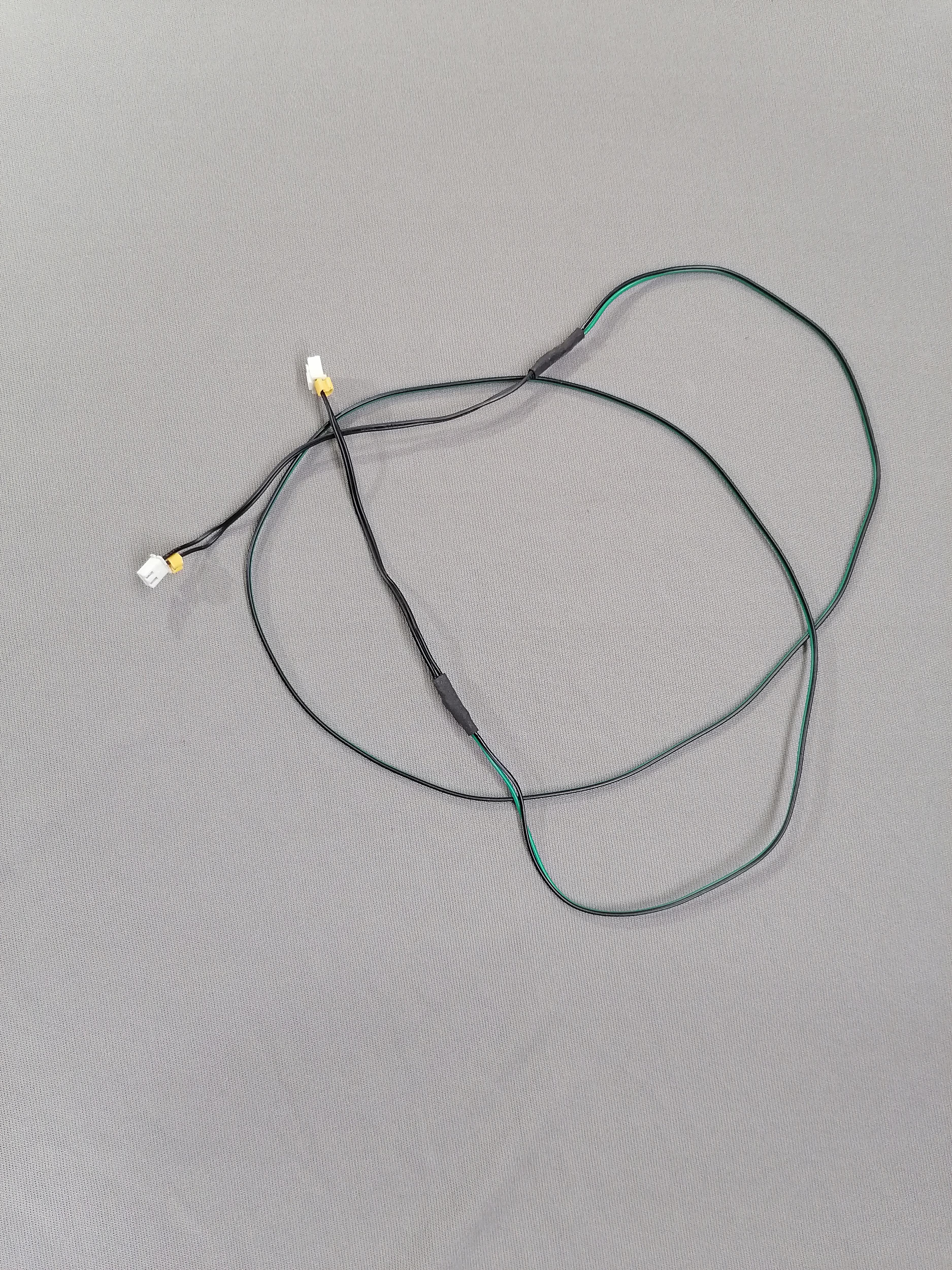
Extend all cables and wires of motors, bed, limit switch , thermistor, hot end, fan and more.
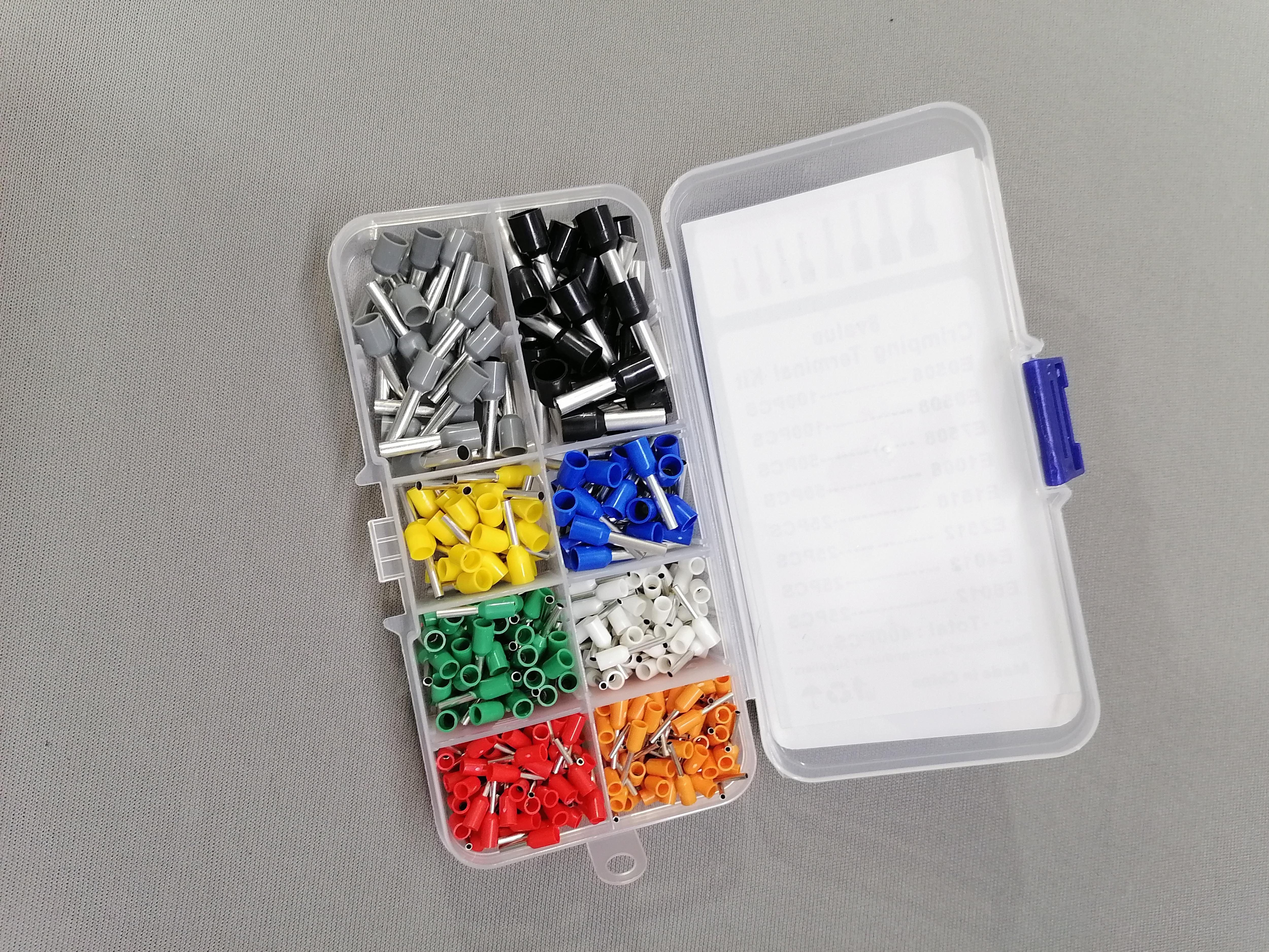
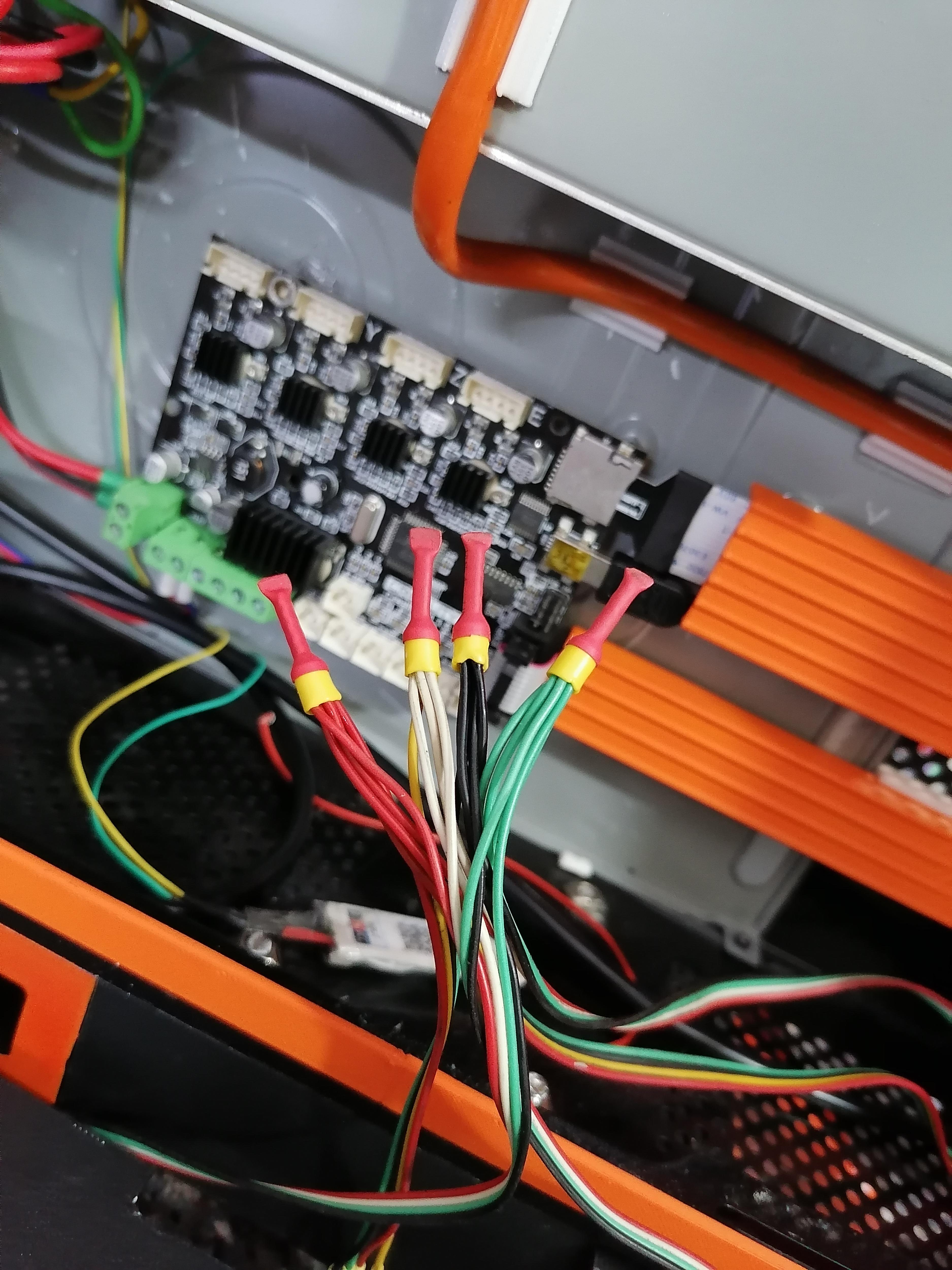
Crimping All Wire Ends
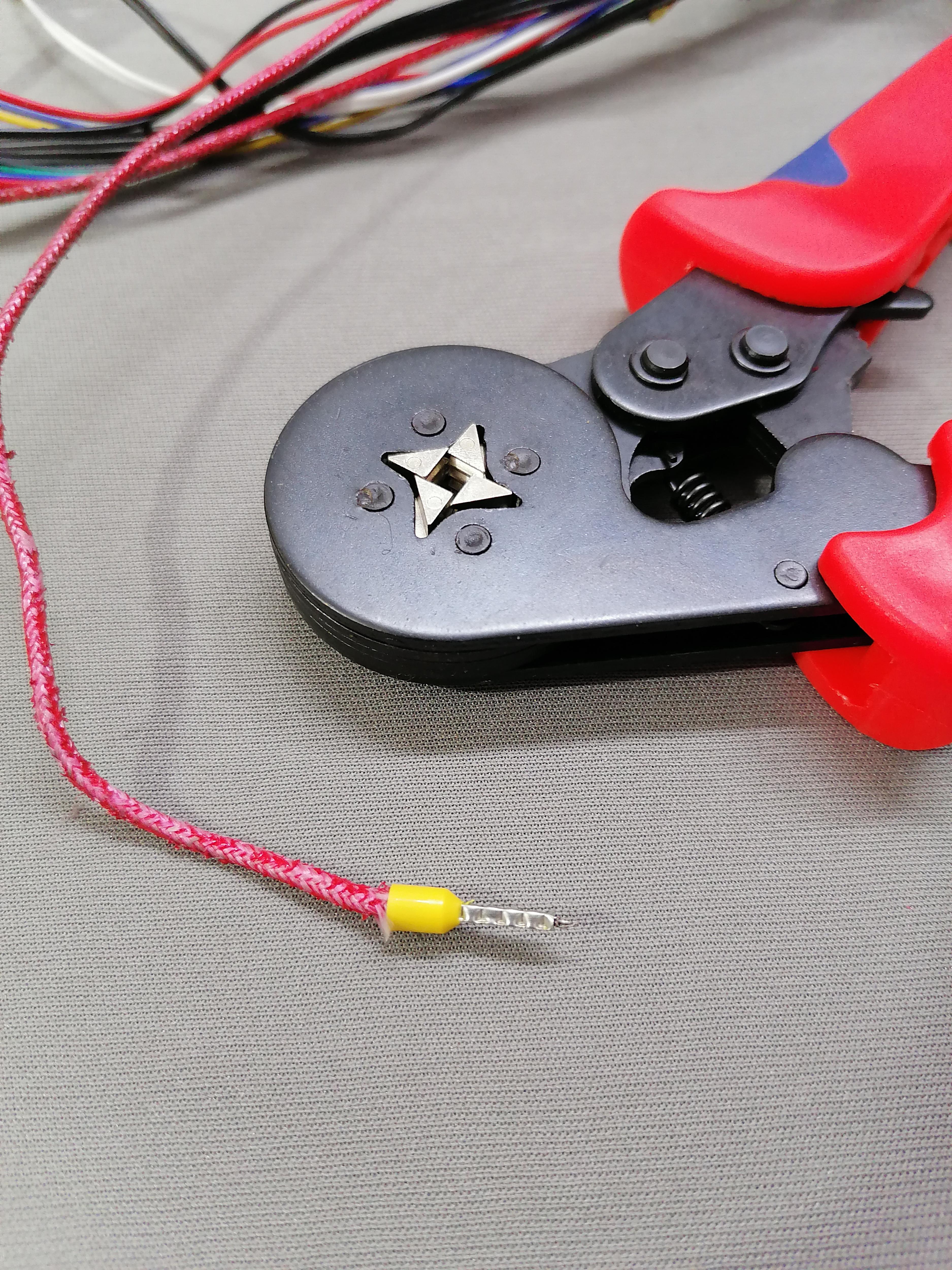
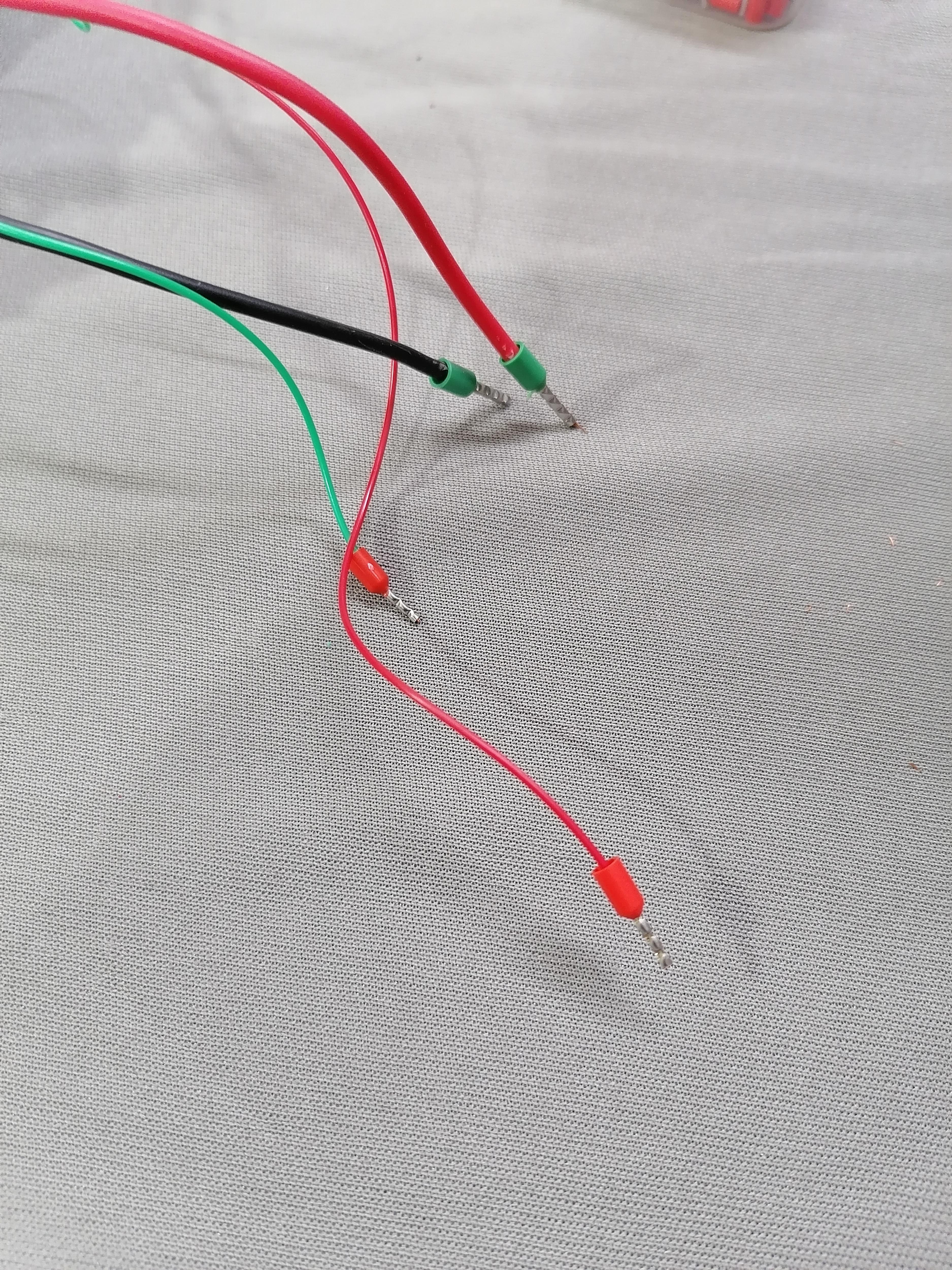
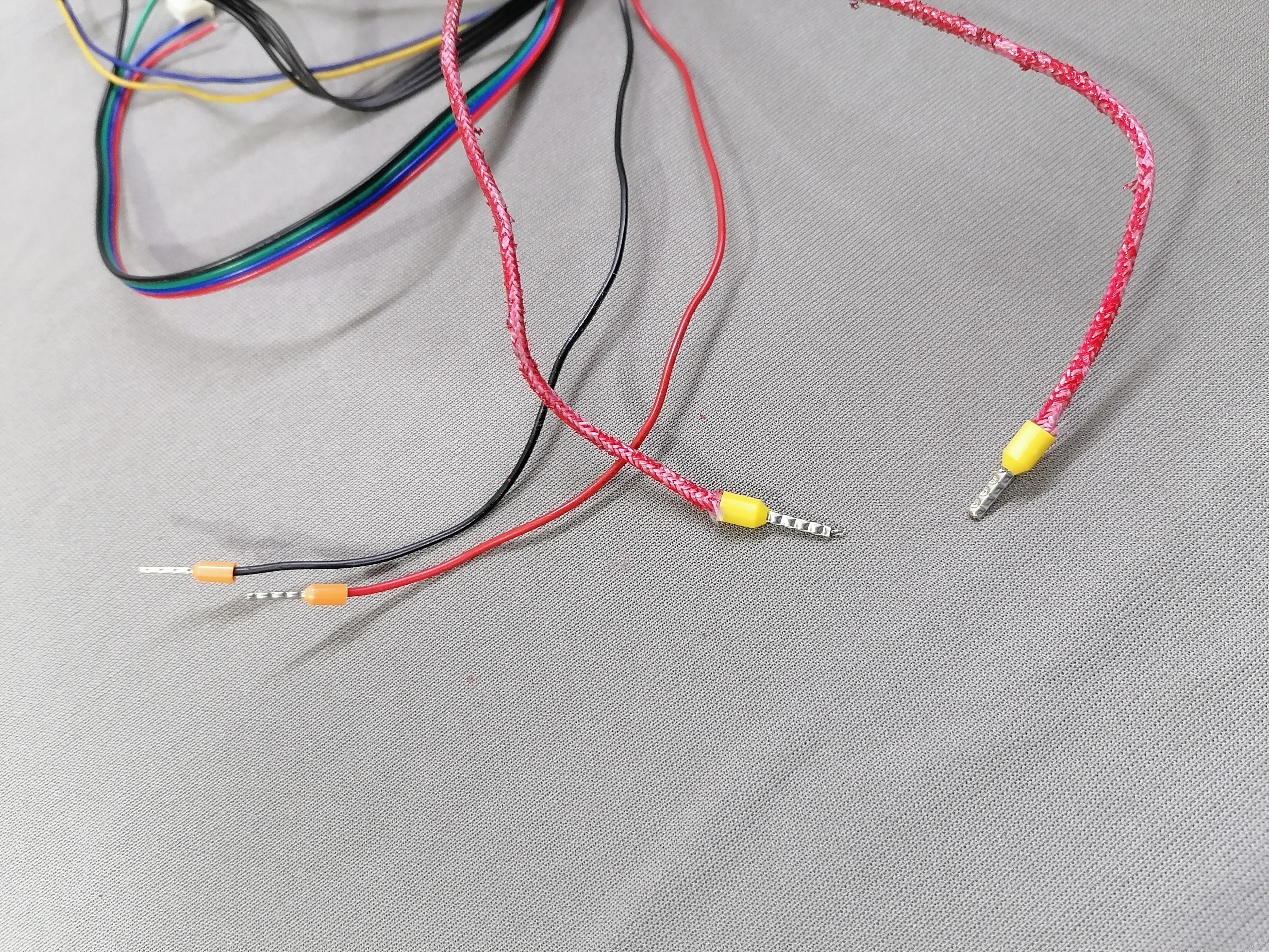
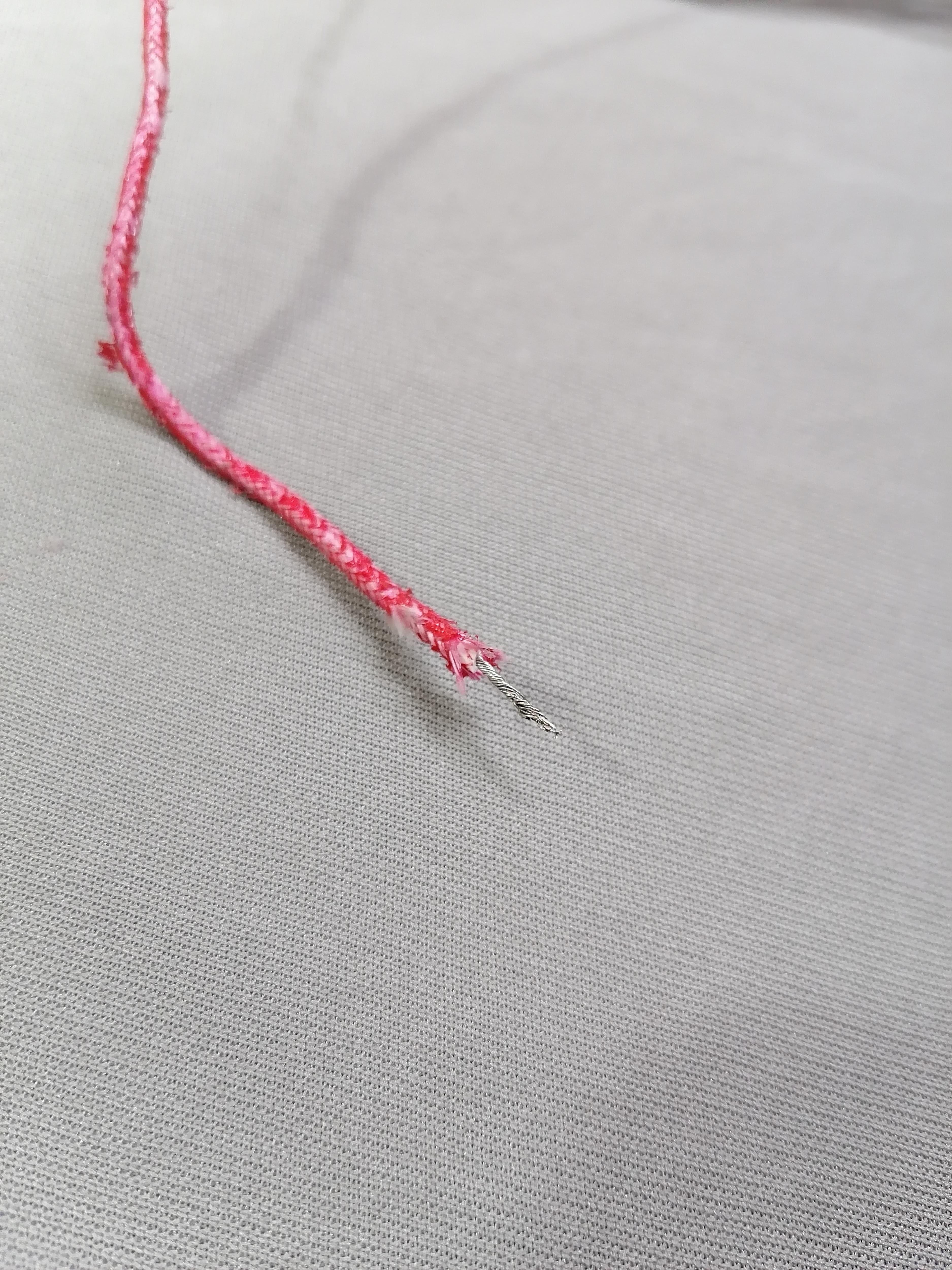

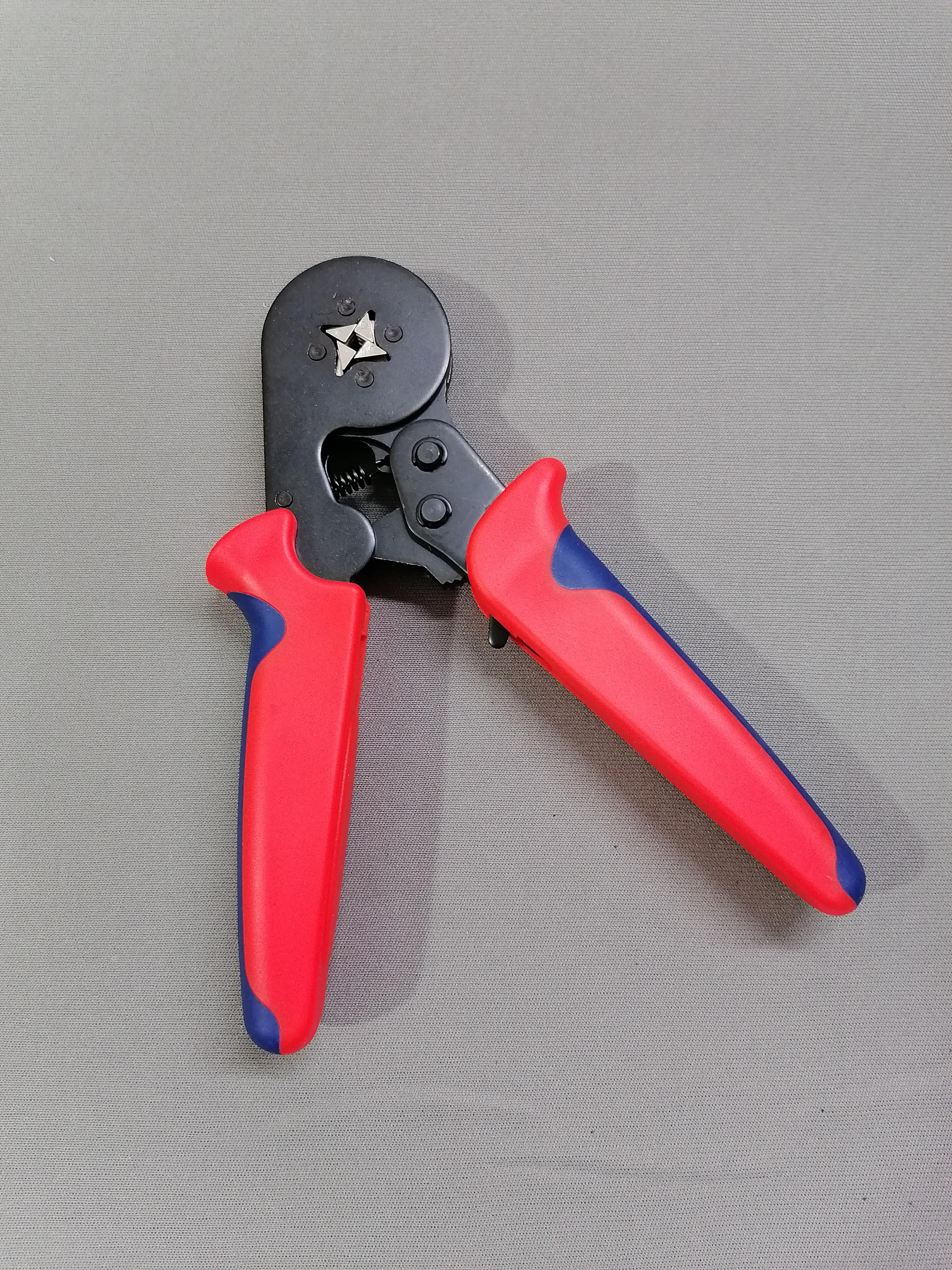
use Crimping tool to crimp all wires ends.
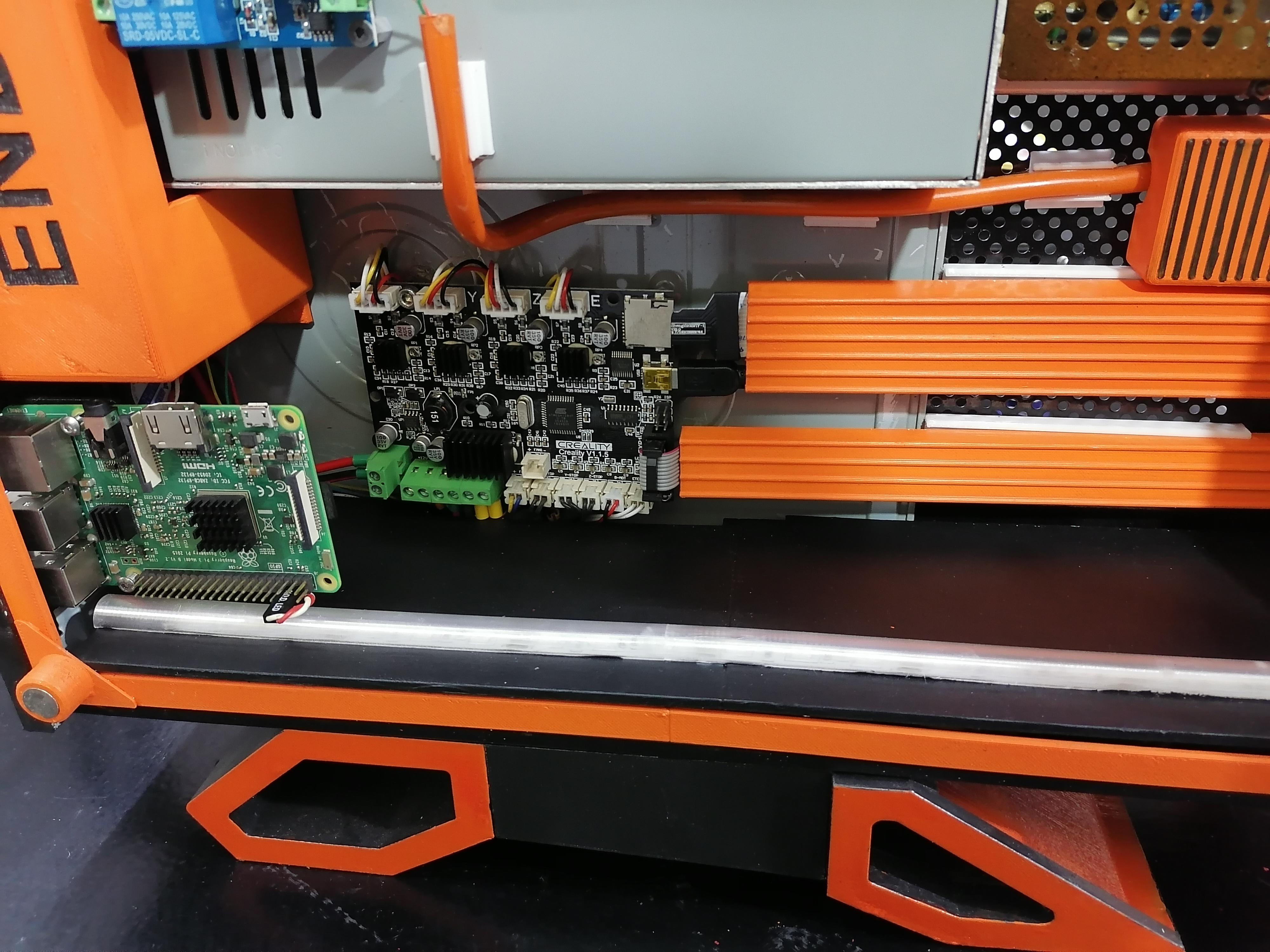
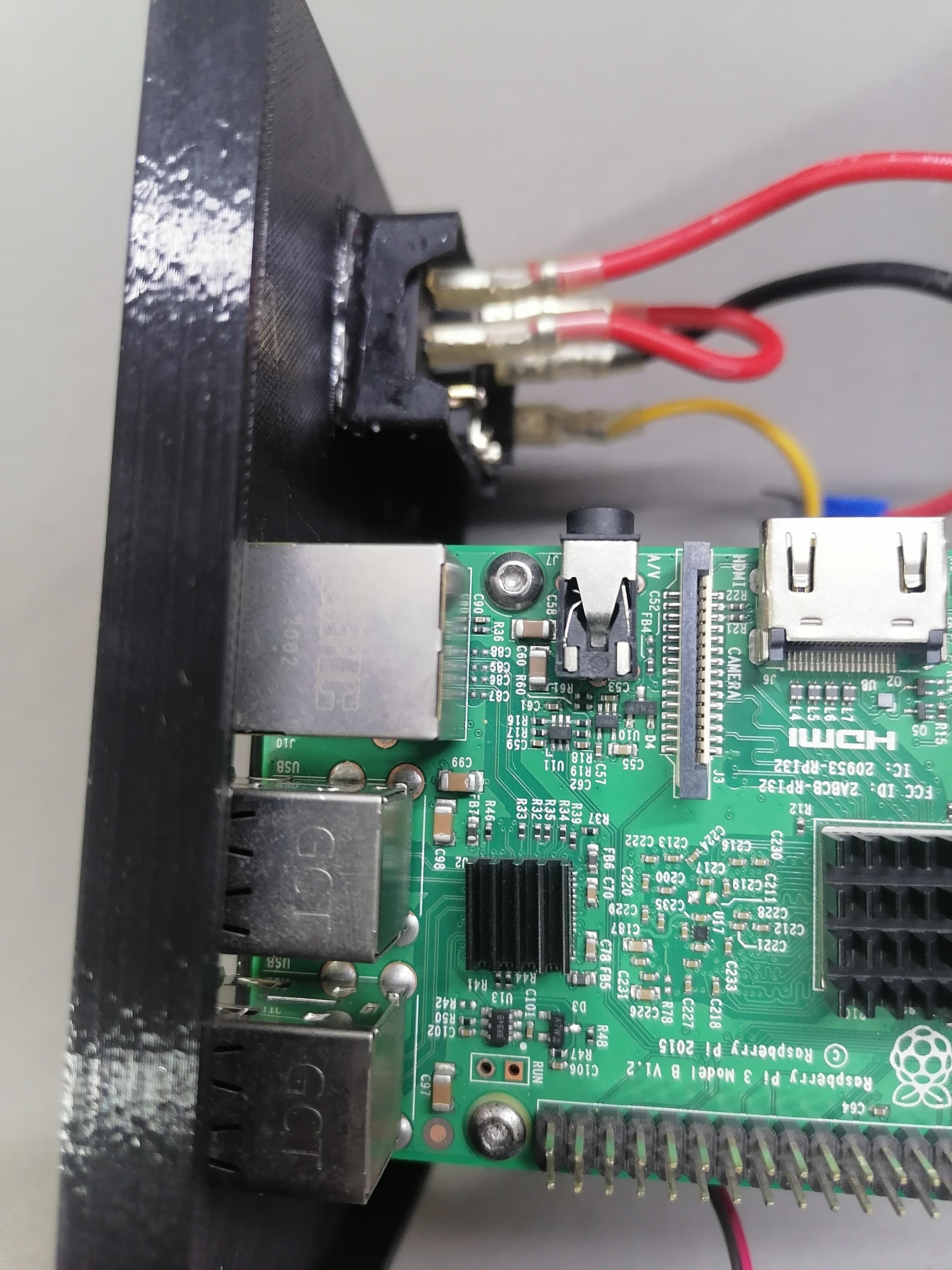
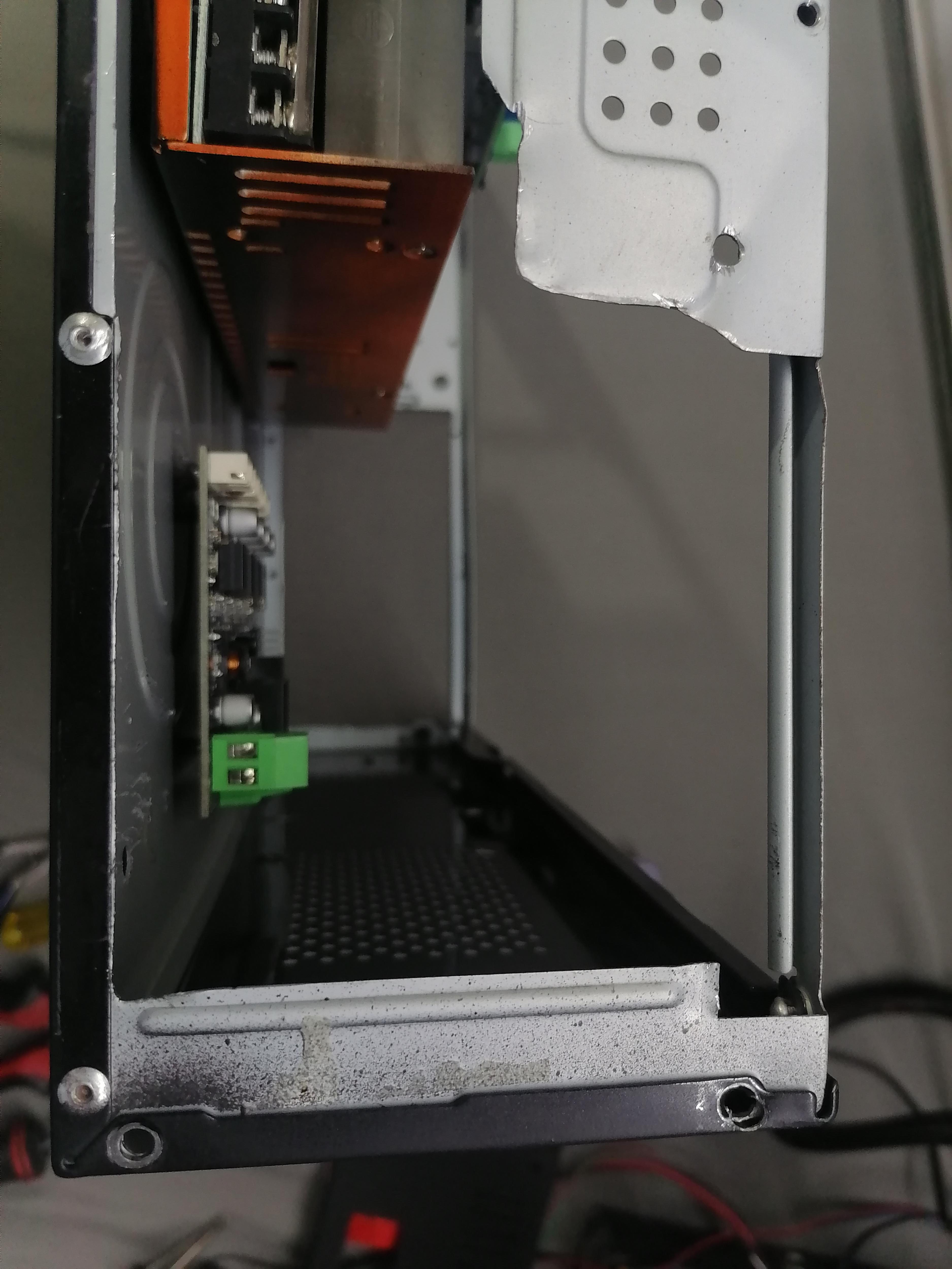
Attach DC-DC Step Down Module to Power the Raspberry Pi
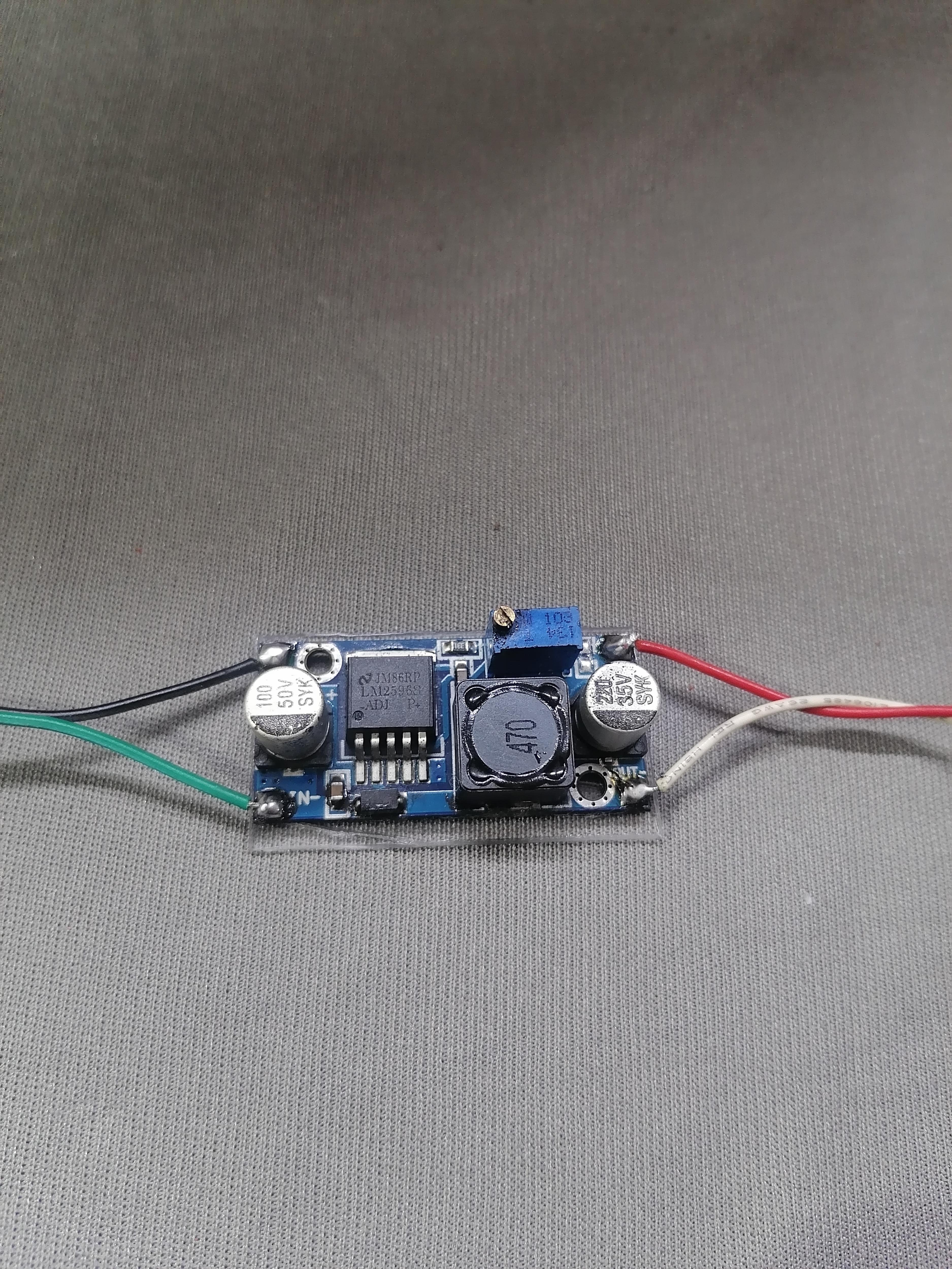
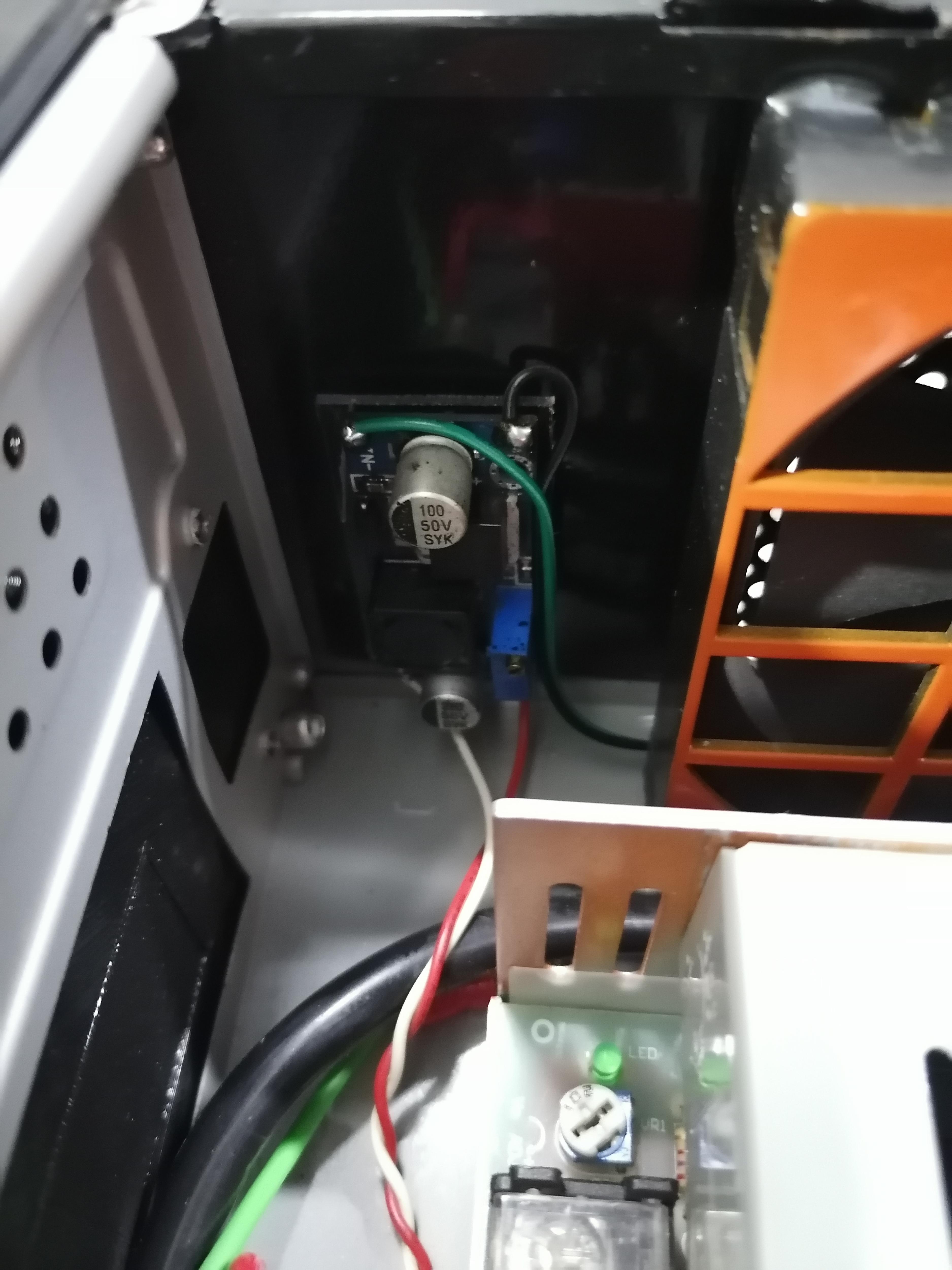
Use DC-DC Step Down Module with 5v output set to power up the Raspberry Pi.
Connect it to 5v pin on raspberry pi.
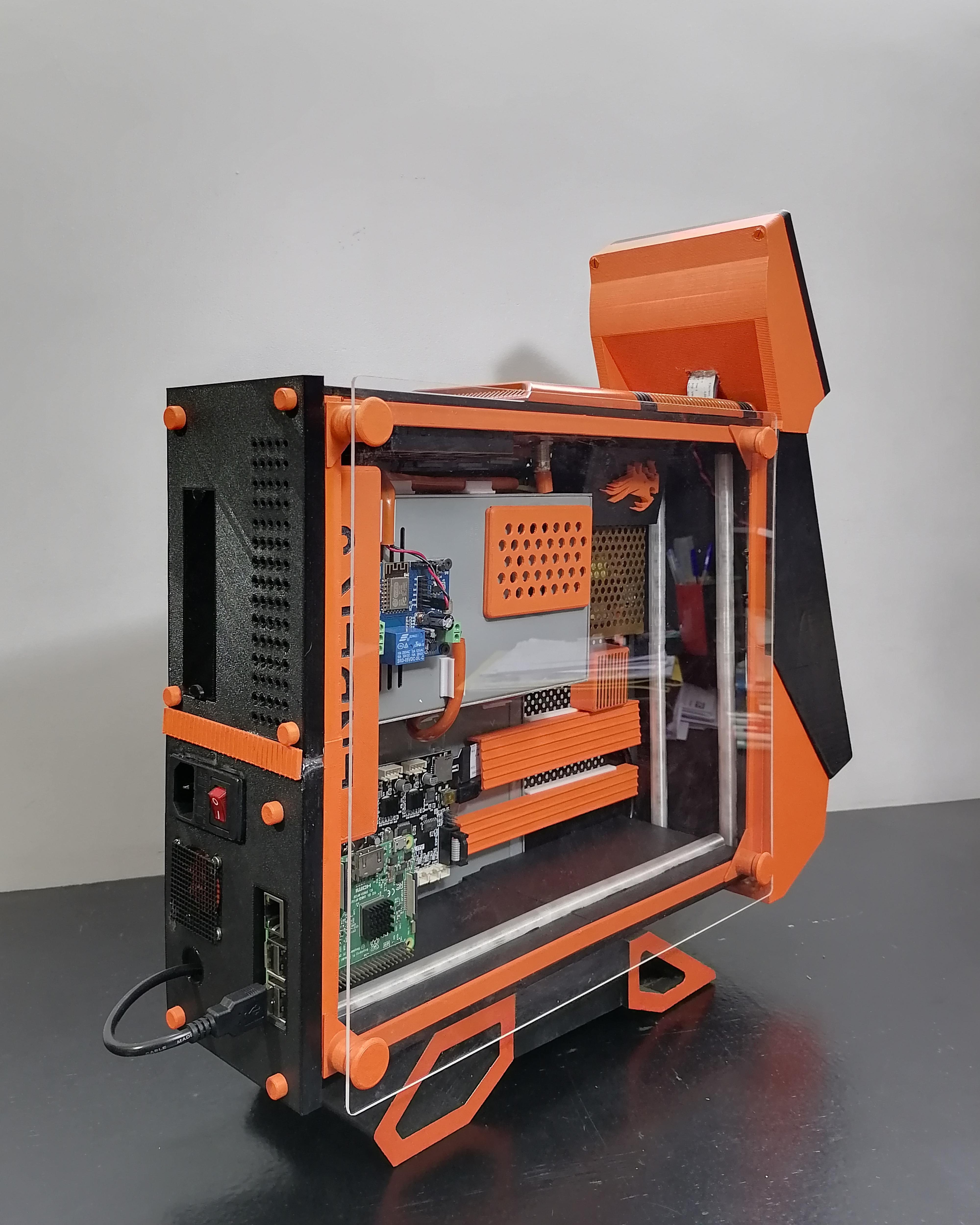
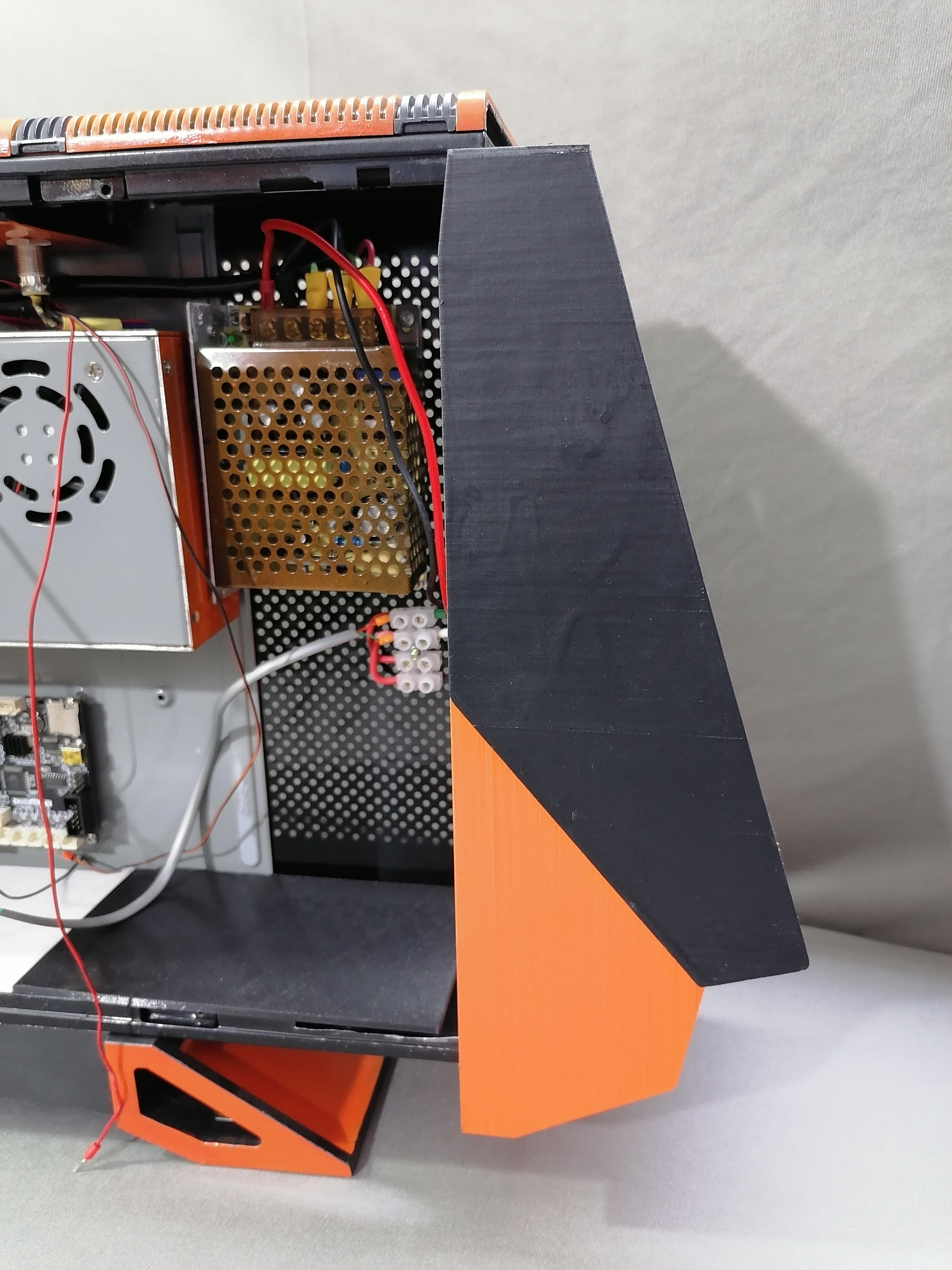
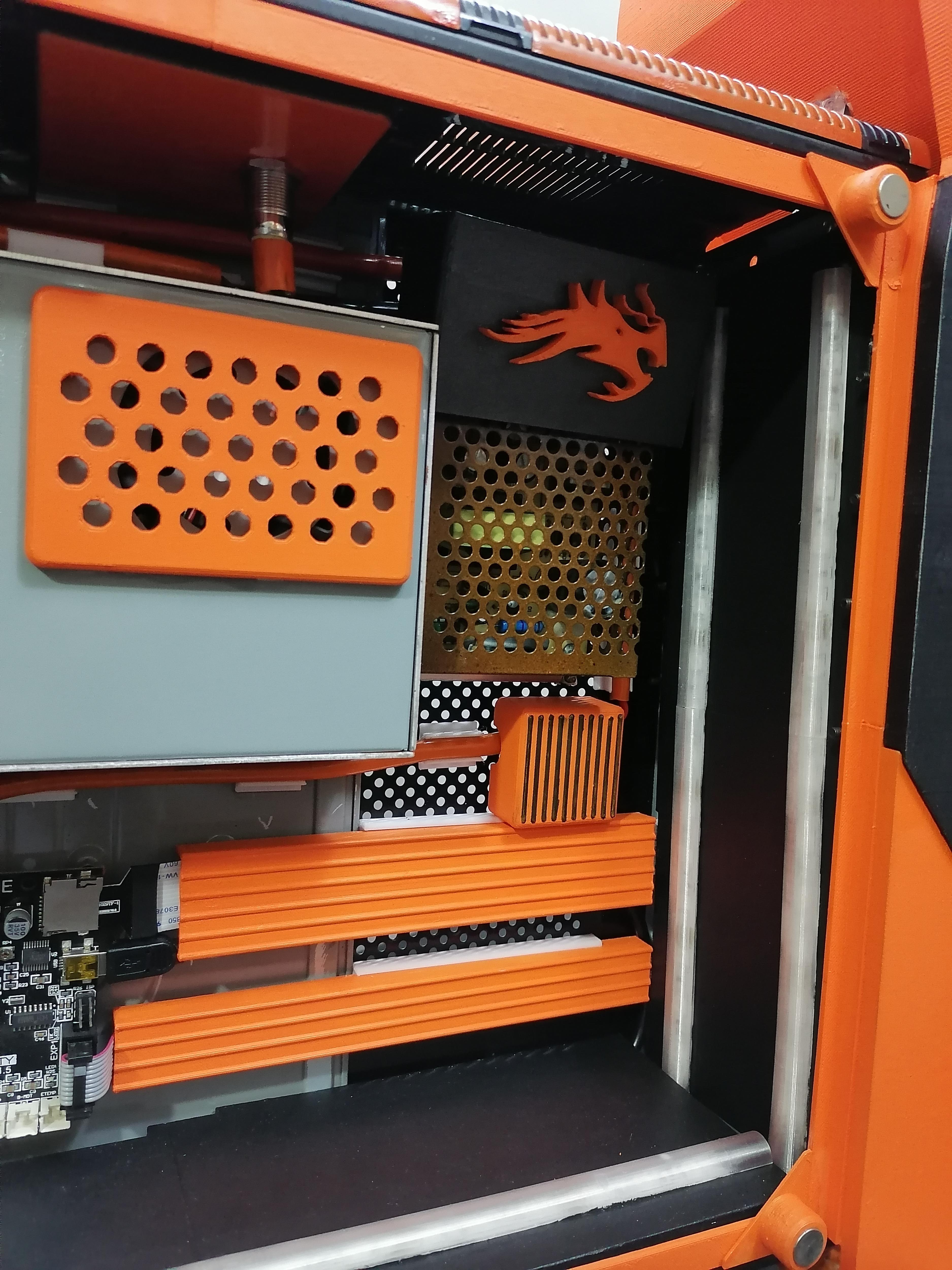
Attaching All Components on Back Plate for CPU
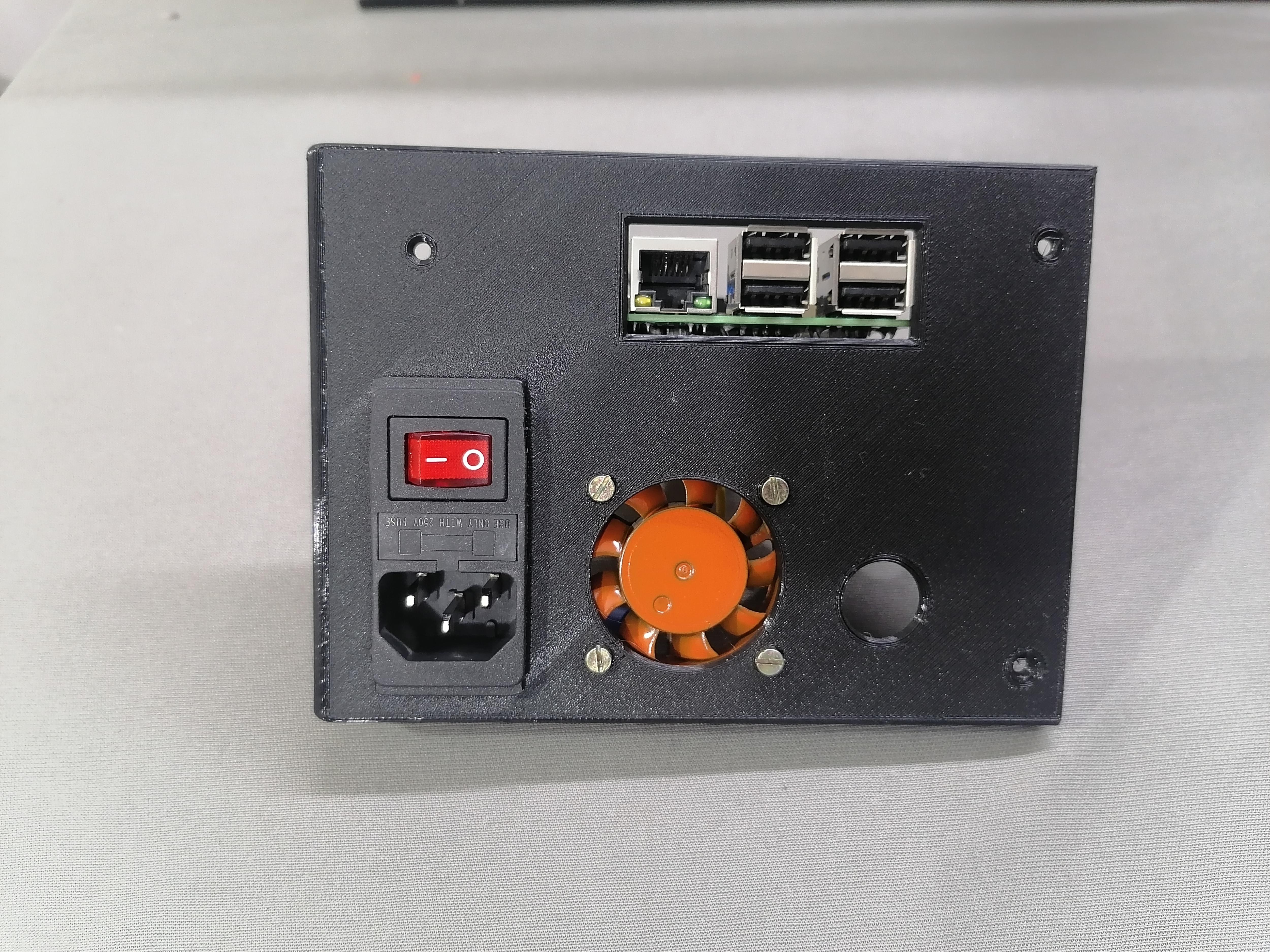
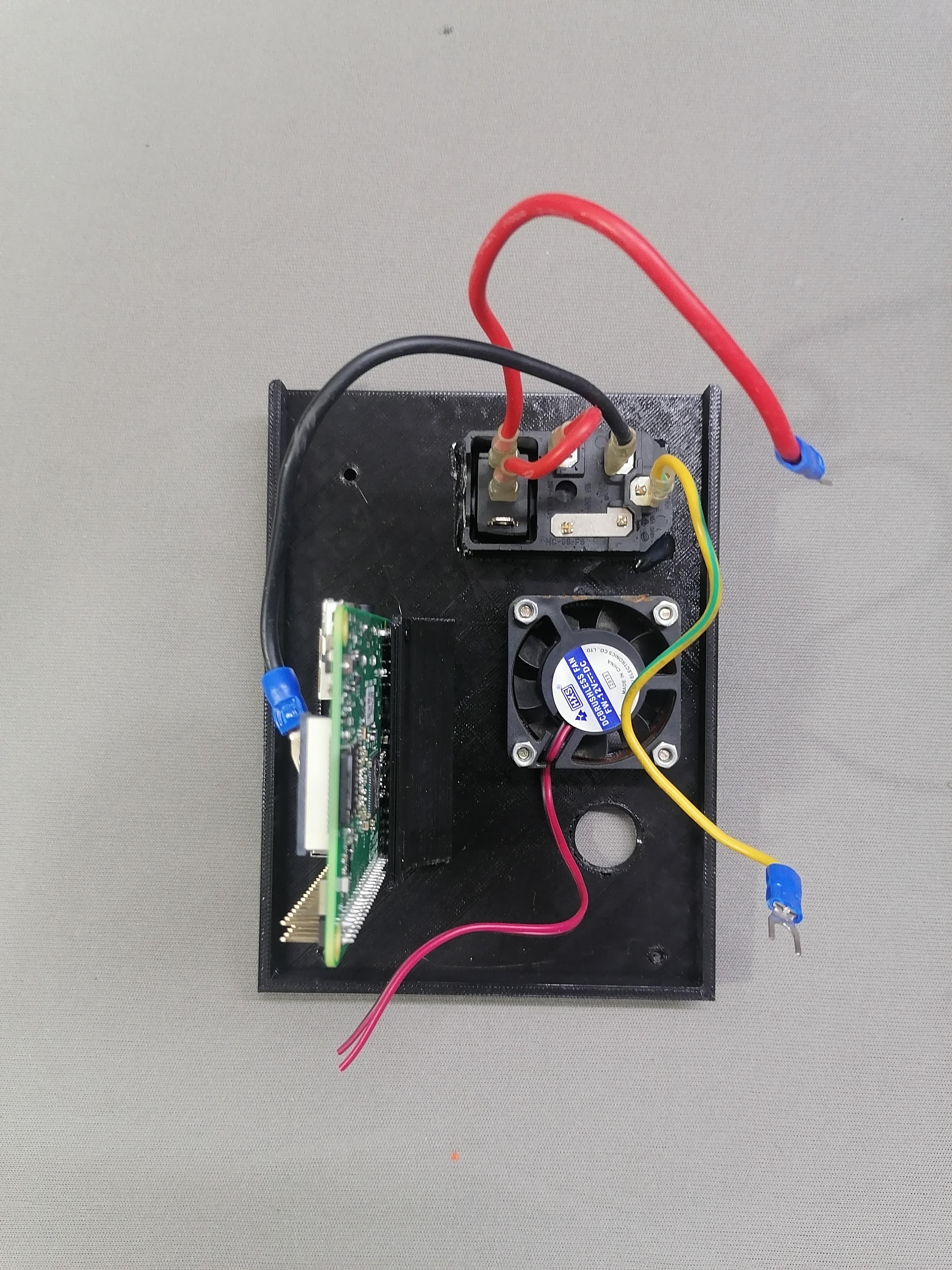
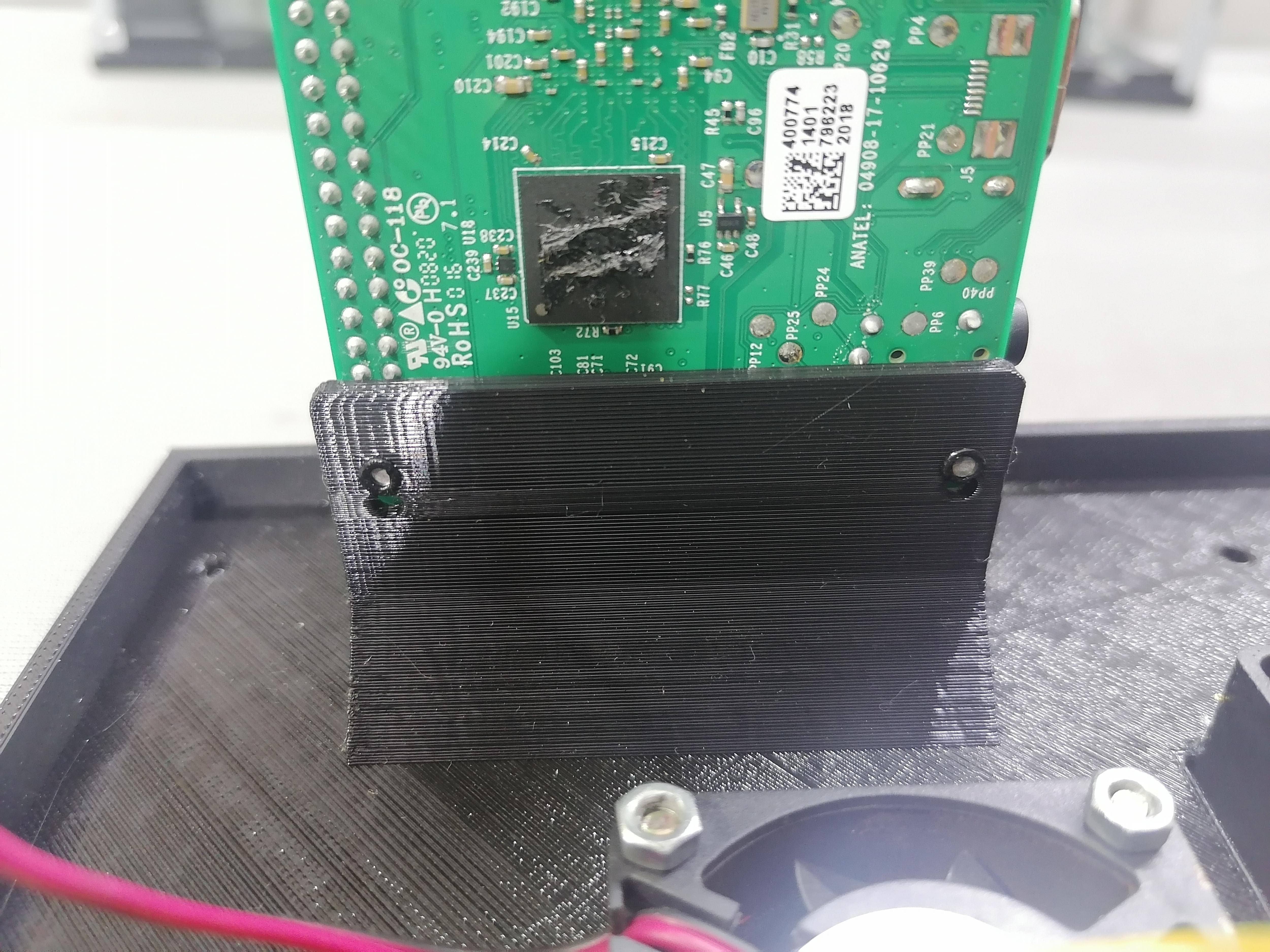
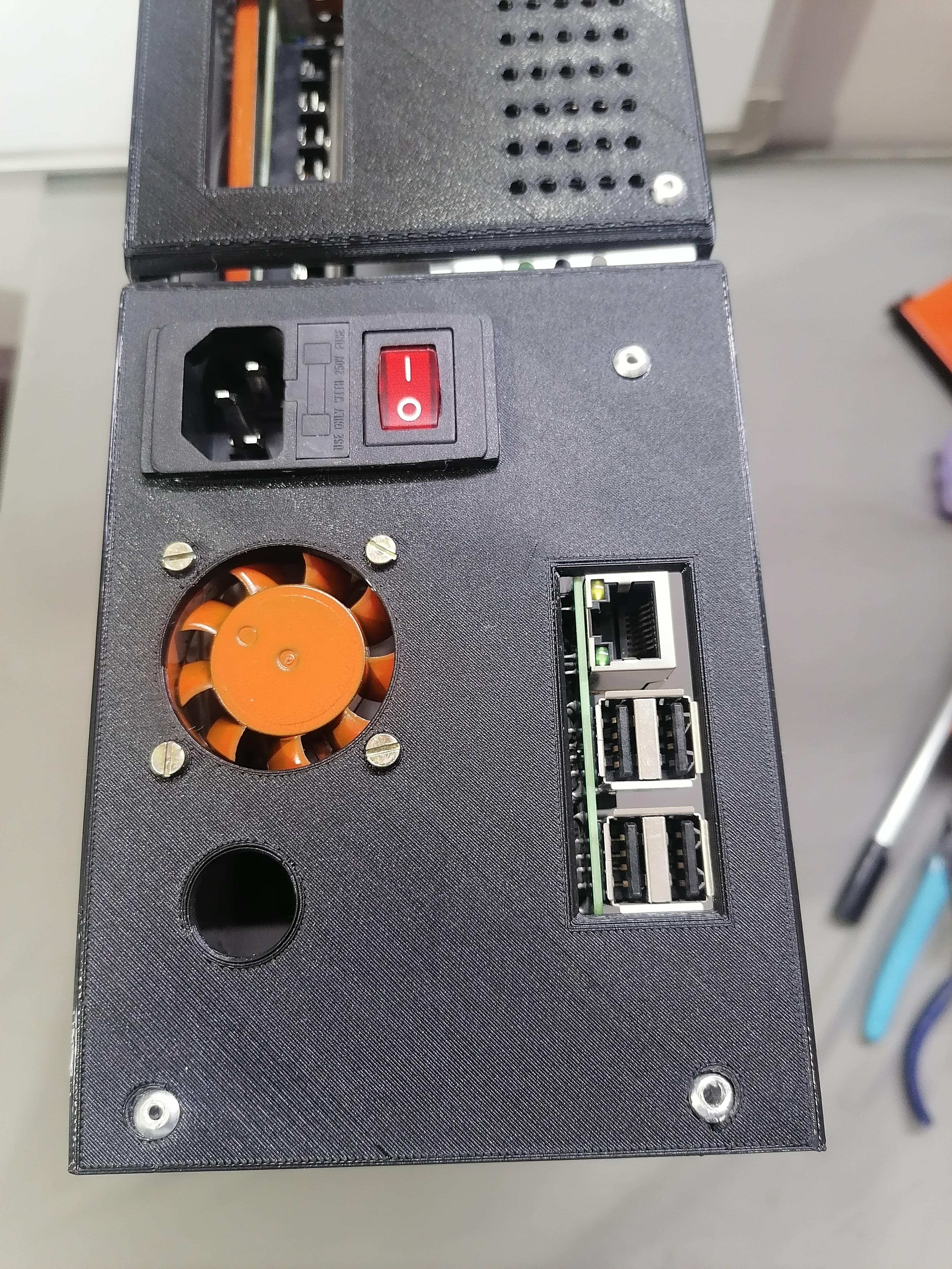
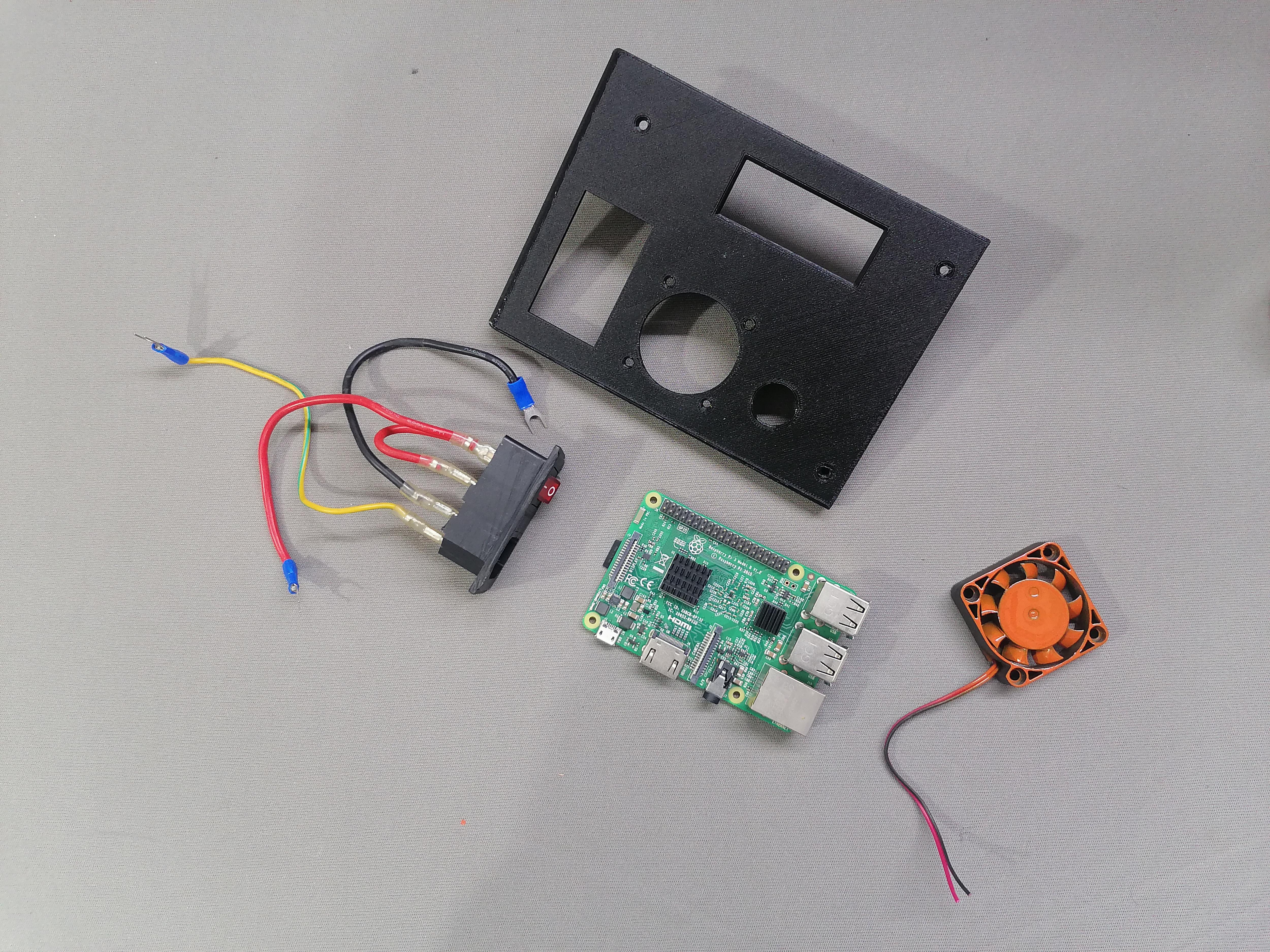
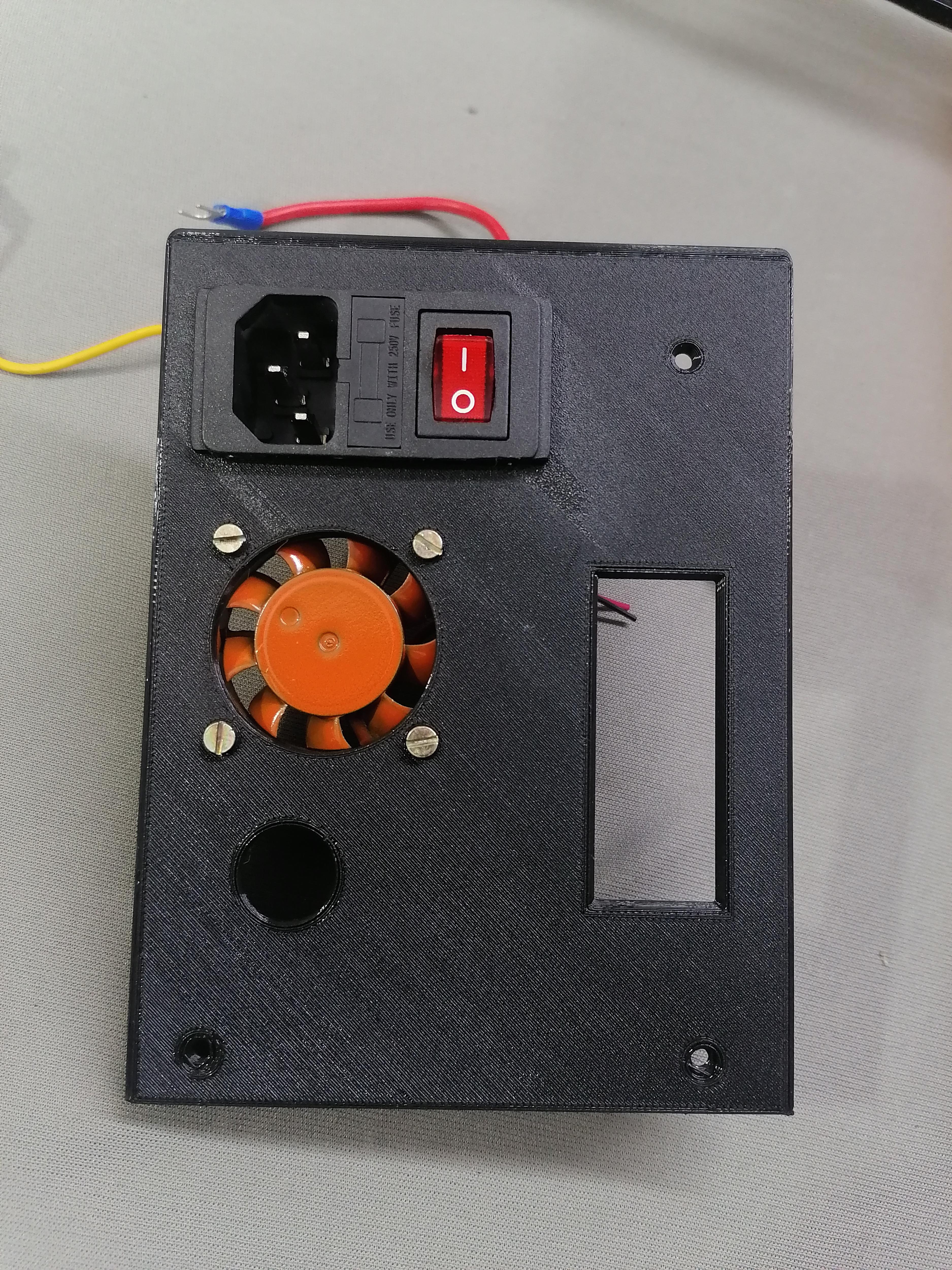
Attach Fan, Supply Switch Plug and Raspberry Pi Bb to the Plate using screws and super glue.
Note: Refer image for more understanding.
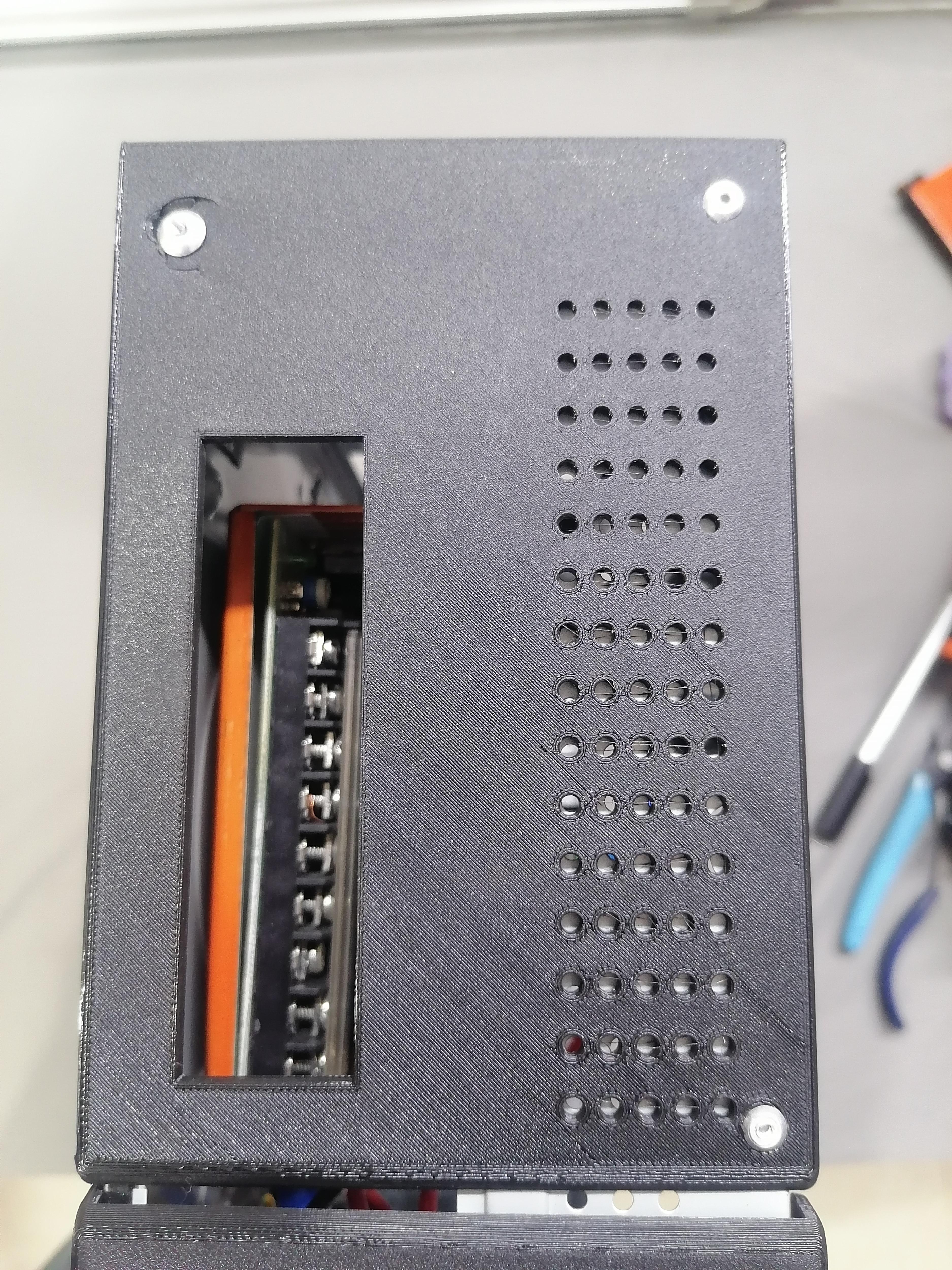
Make Hole at Back of CPU to Attach the Back Plates
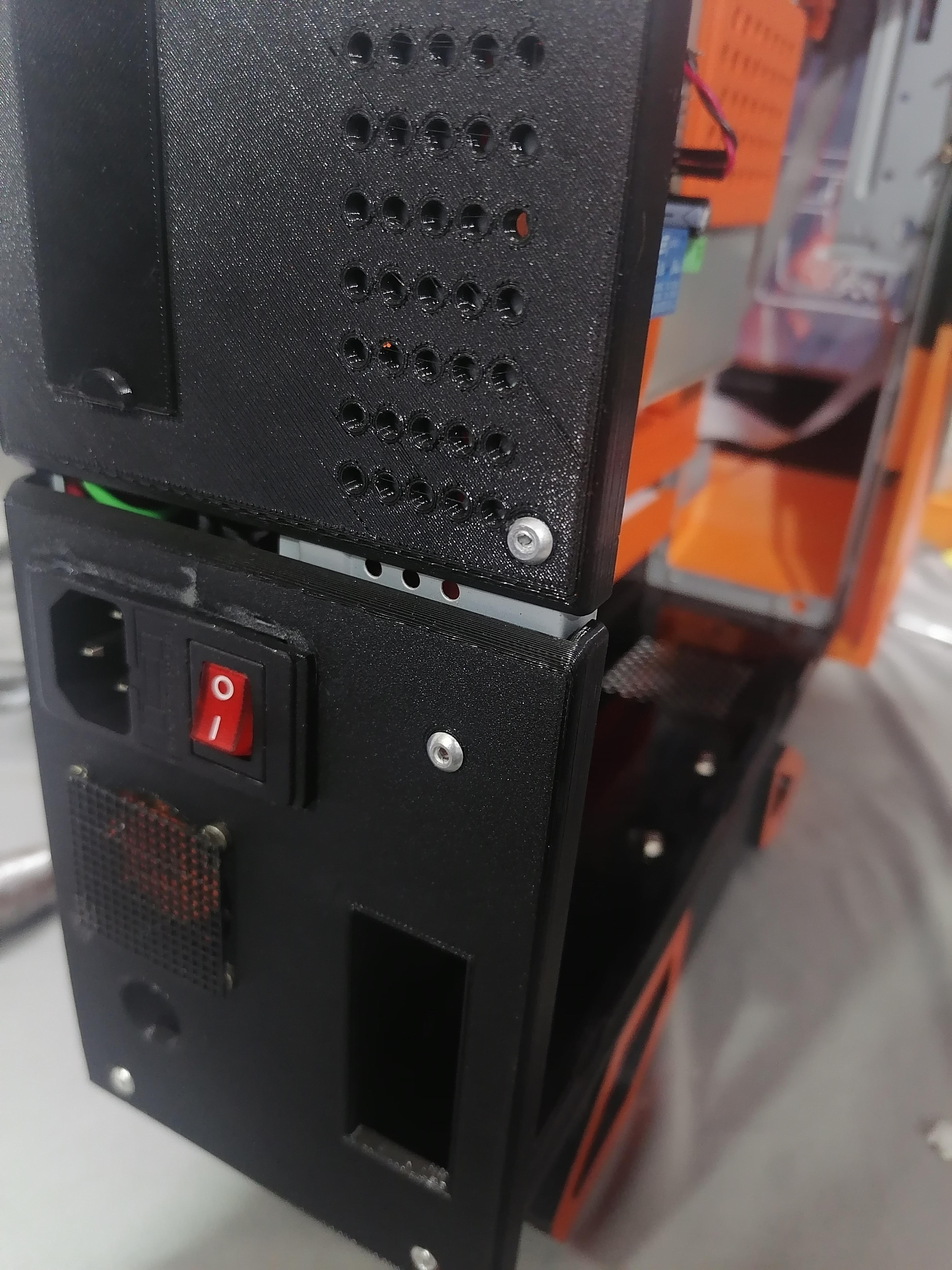
Make hole and attach the back plates using rivets.
Note: Refer image for more understanding.
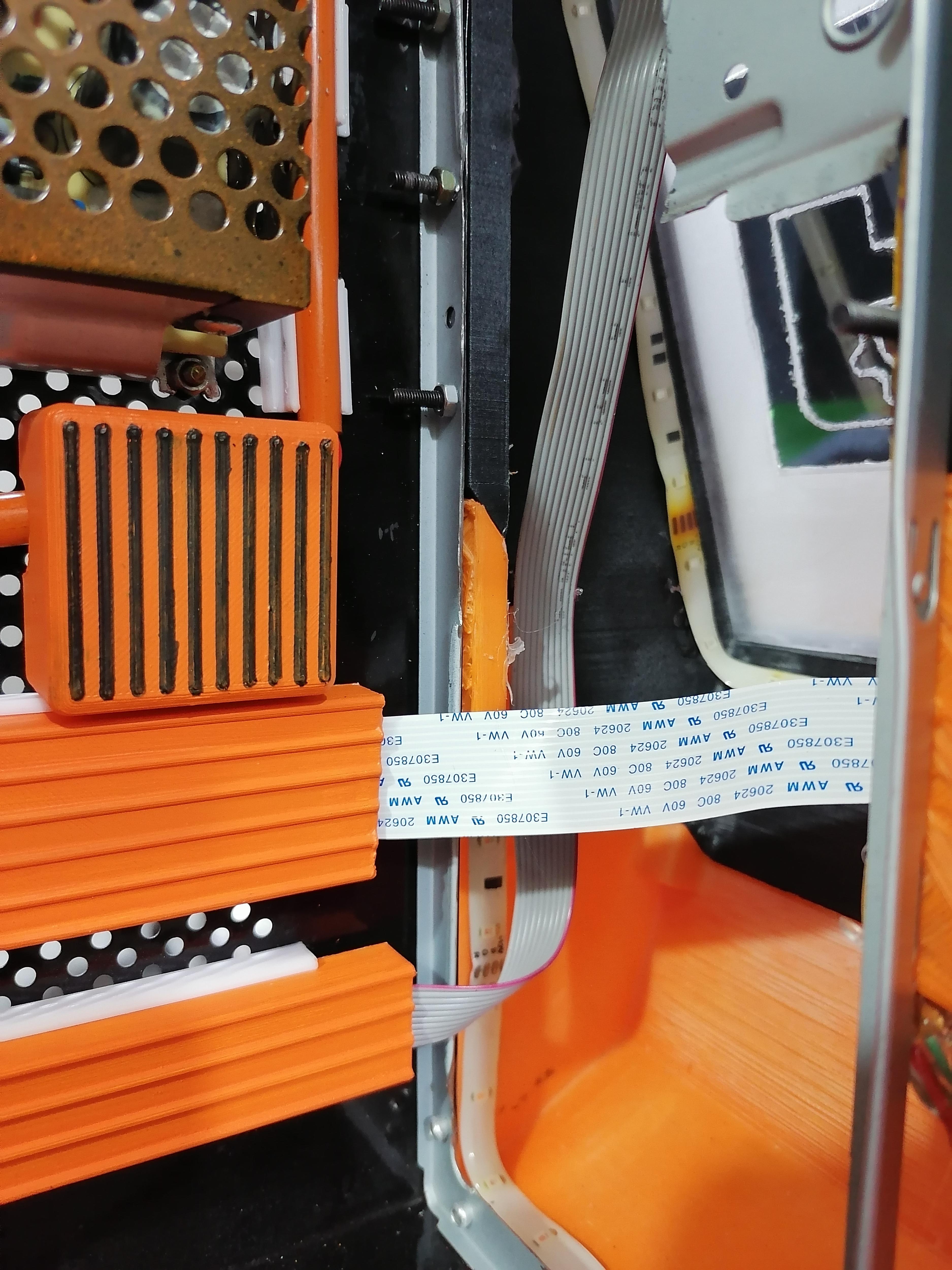
Cut the Flexible PVC Pipe 7mm and Pass Wire in It
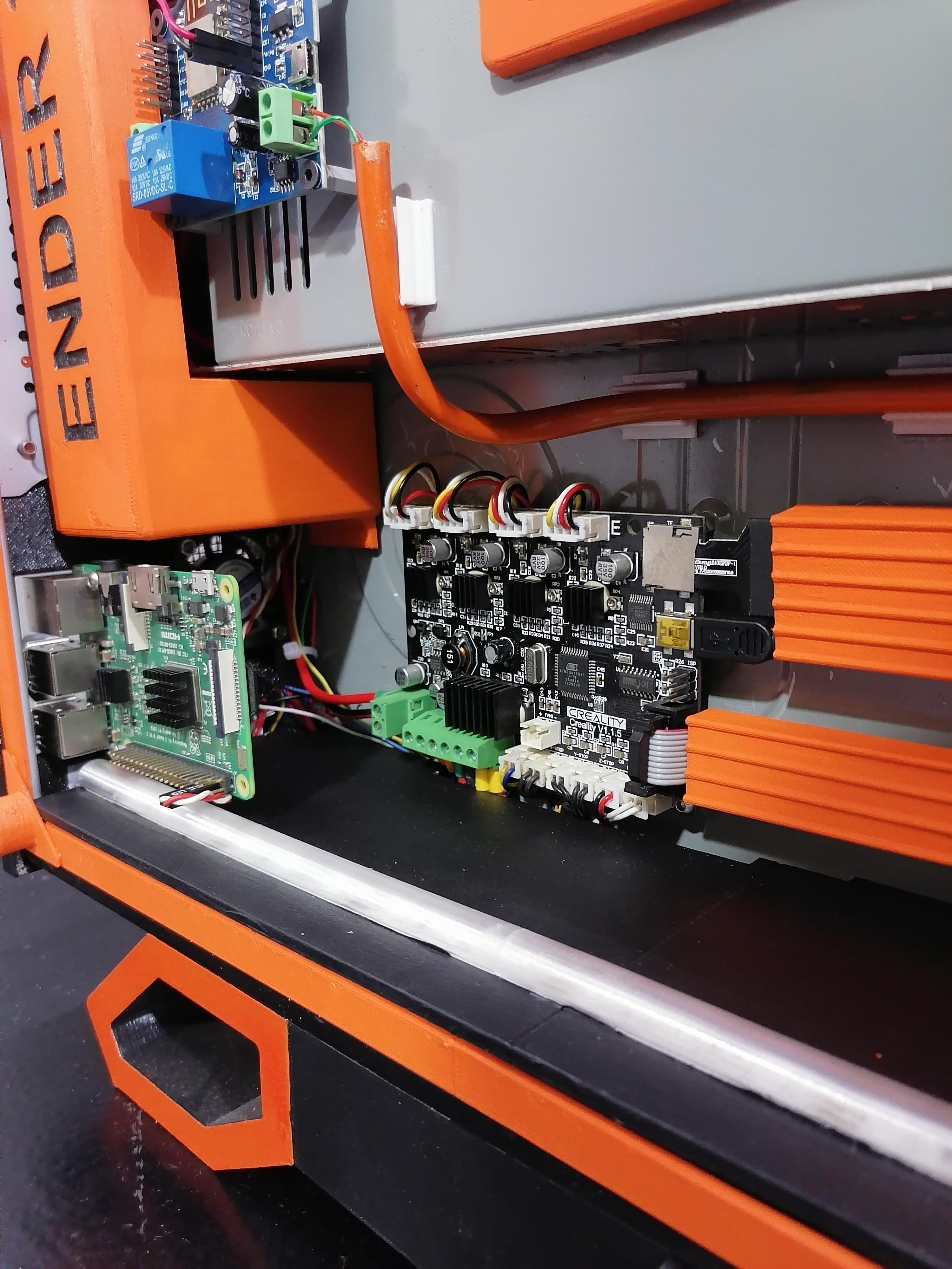

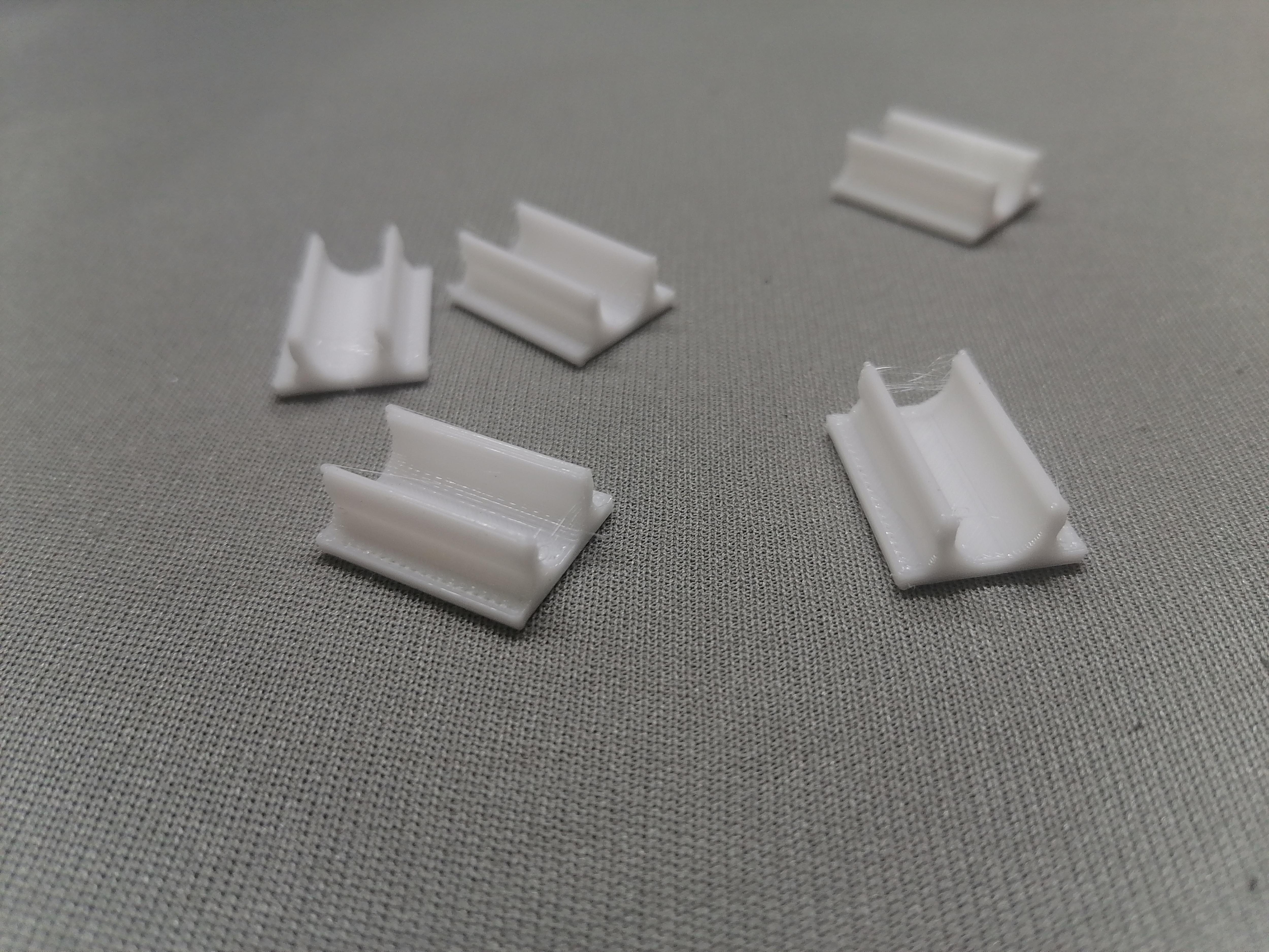
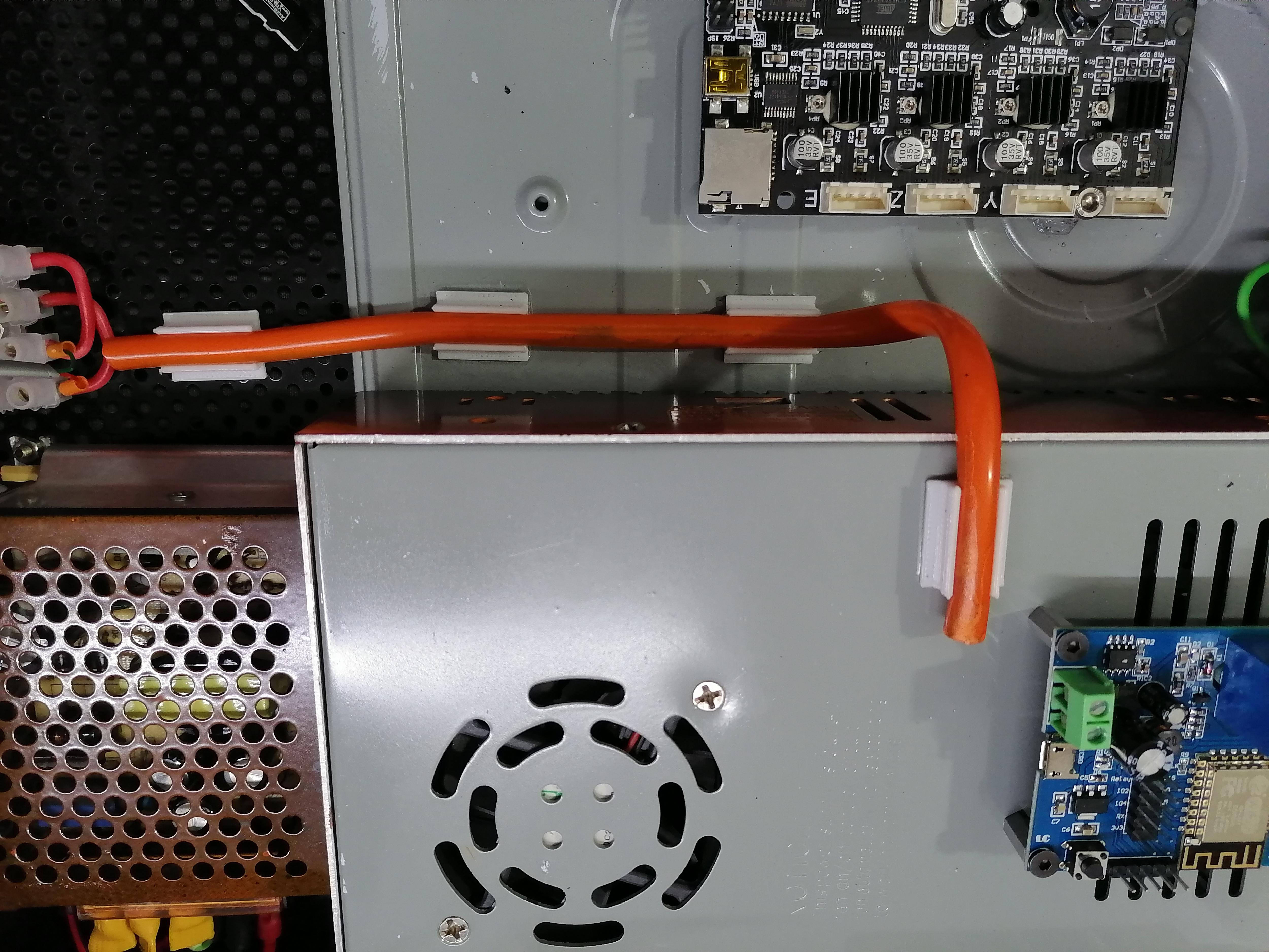
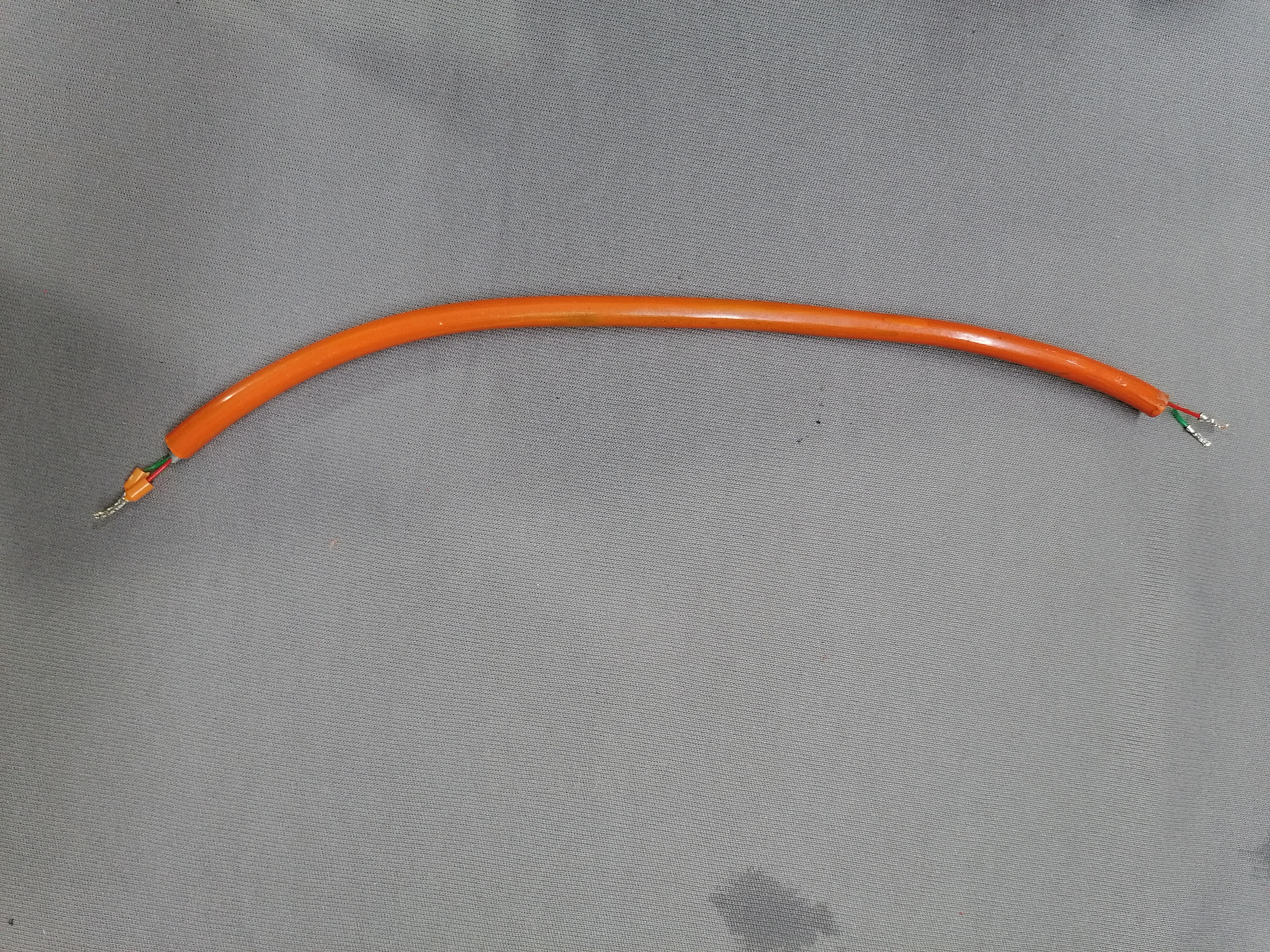
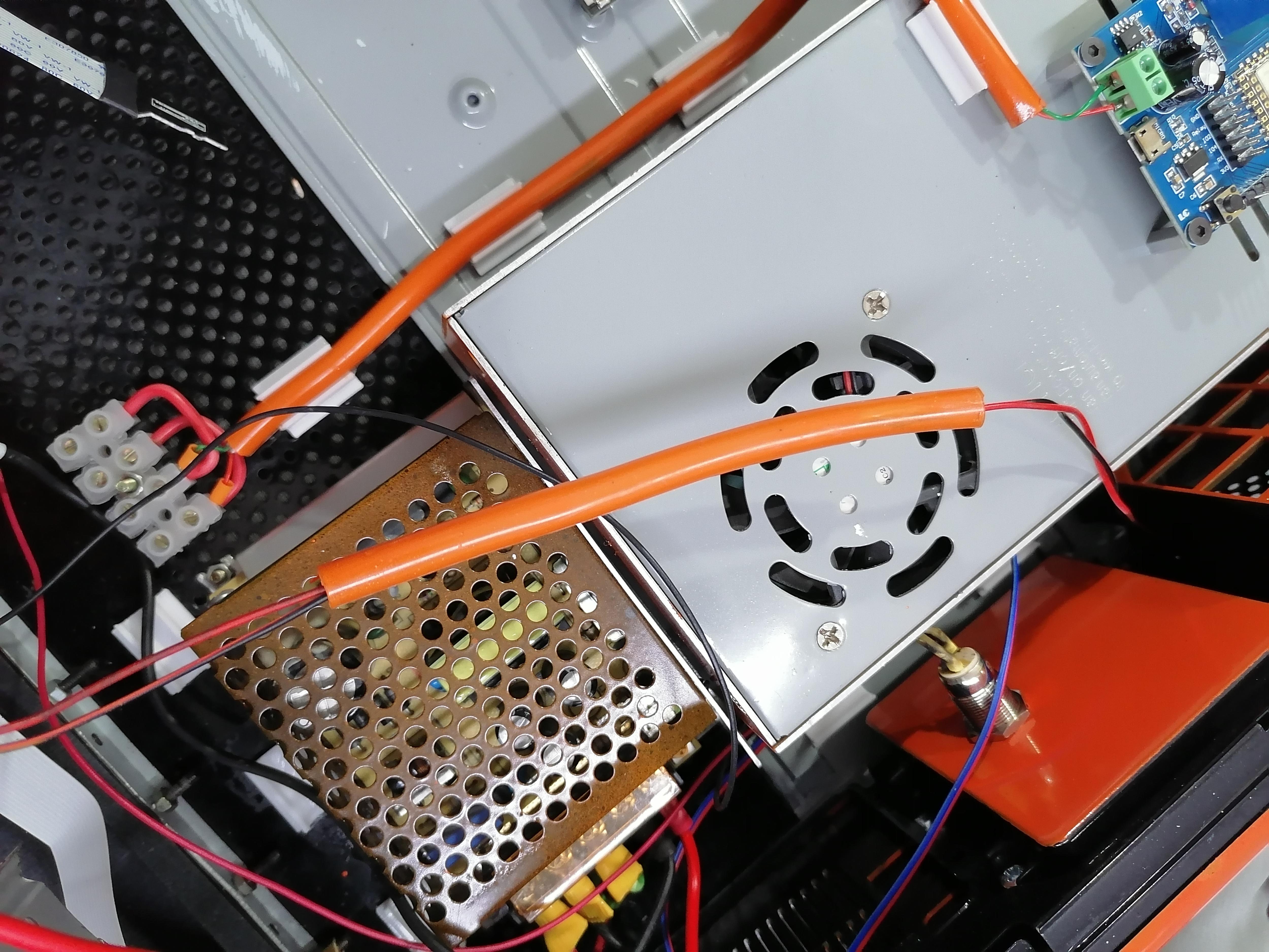
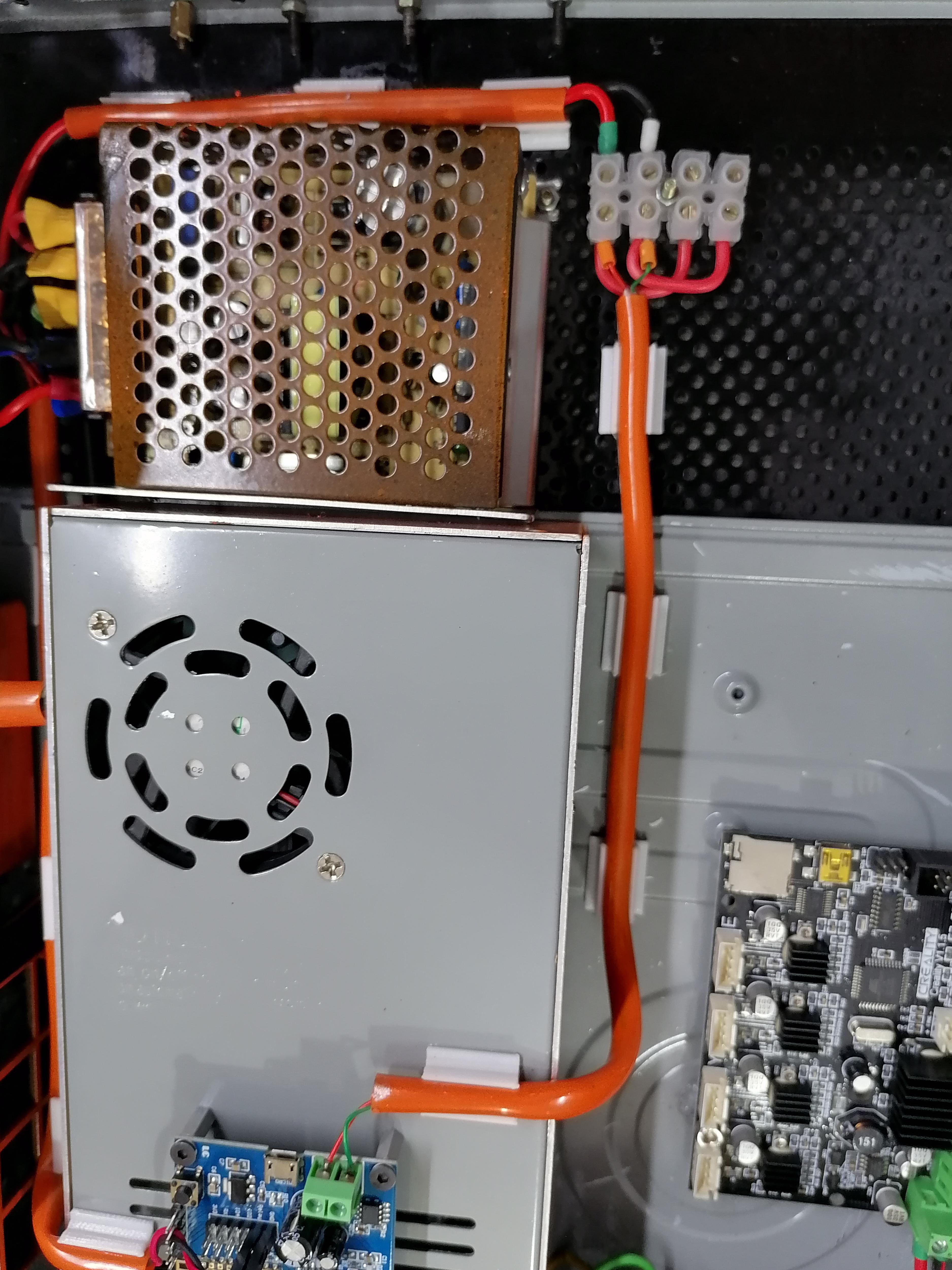
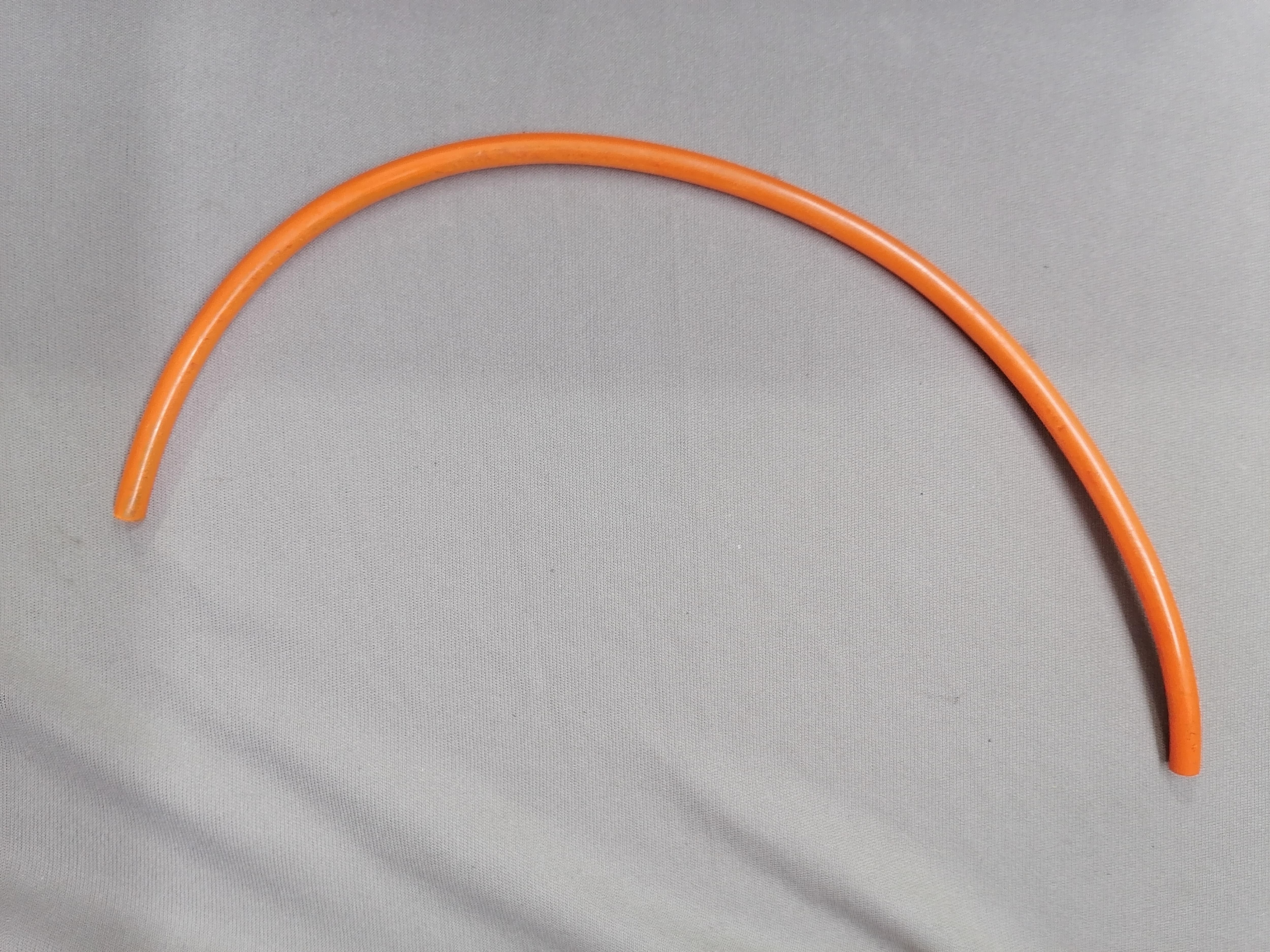
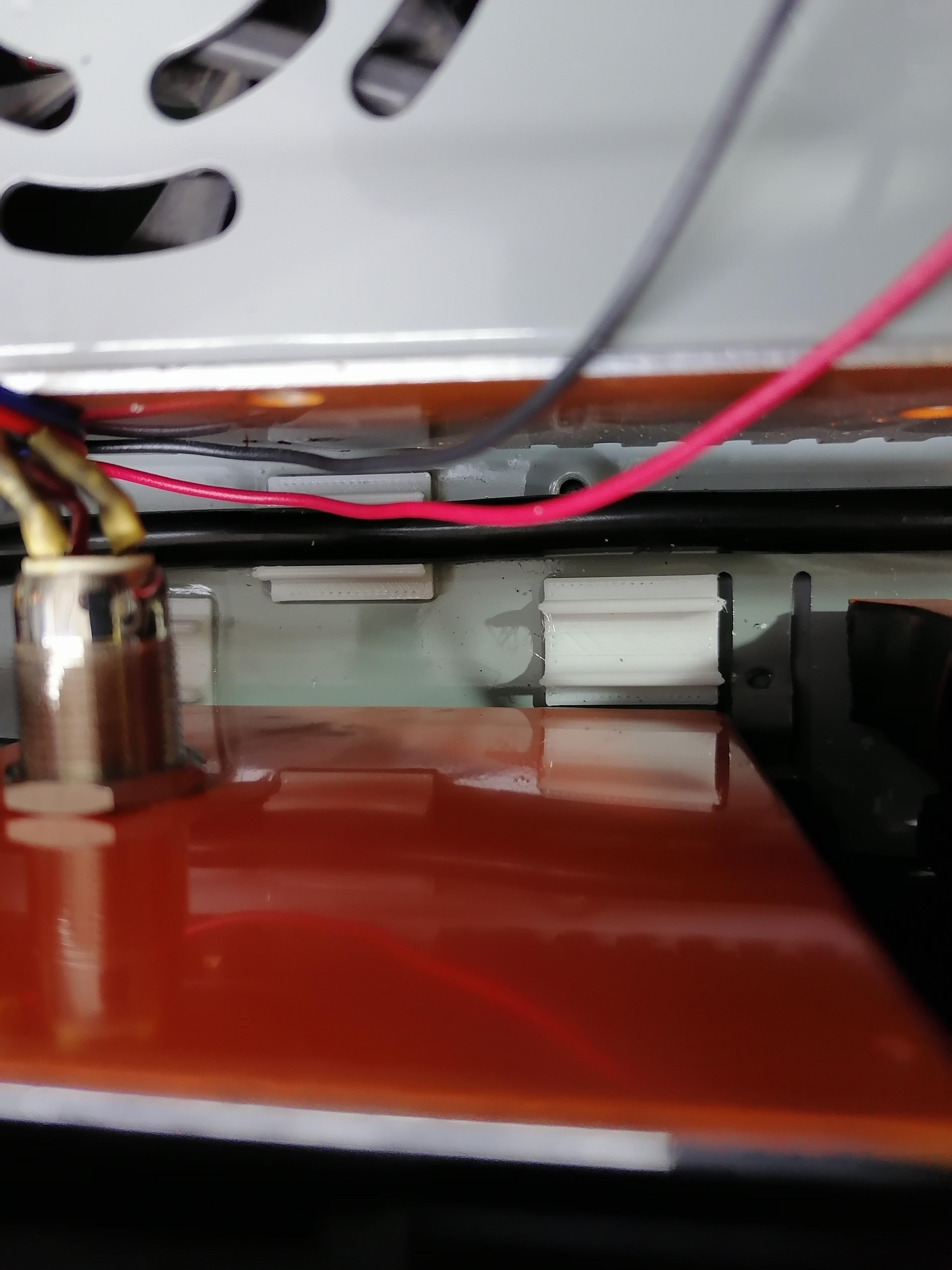
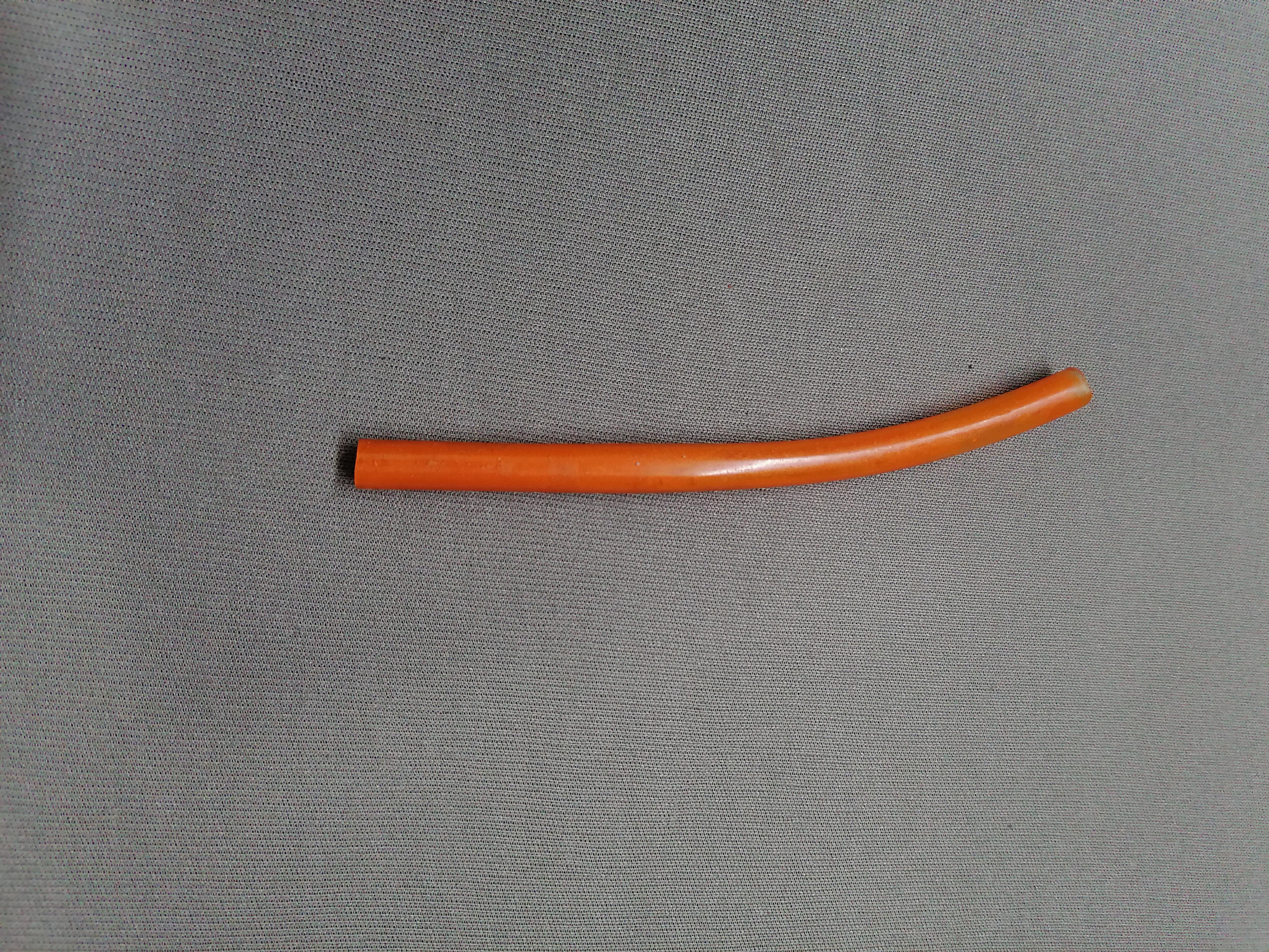
Here I use Transparent Flexible PVC pipe then I put orange colour in pipe to look nice. Use Pipe holder and stick it on the metal surface of CPU using super glue.
Note: Refer image for more understanding.
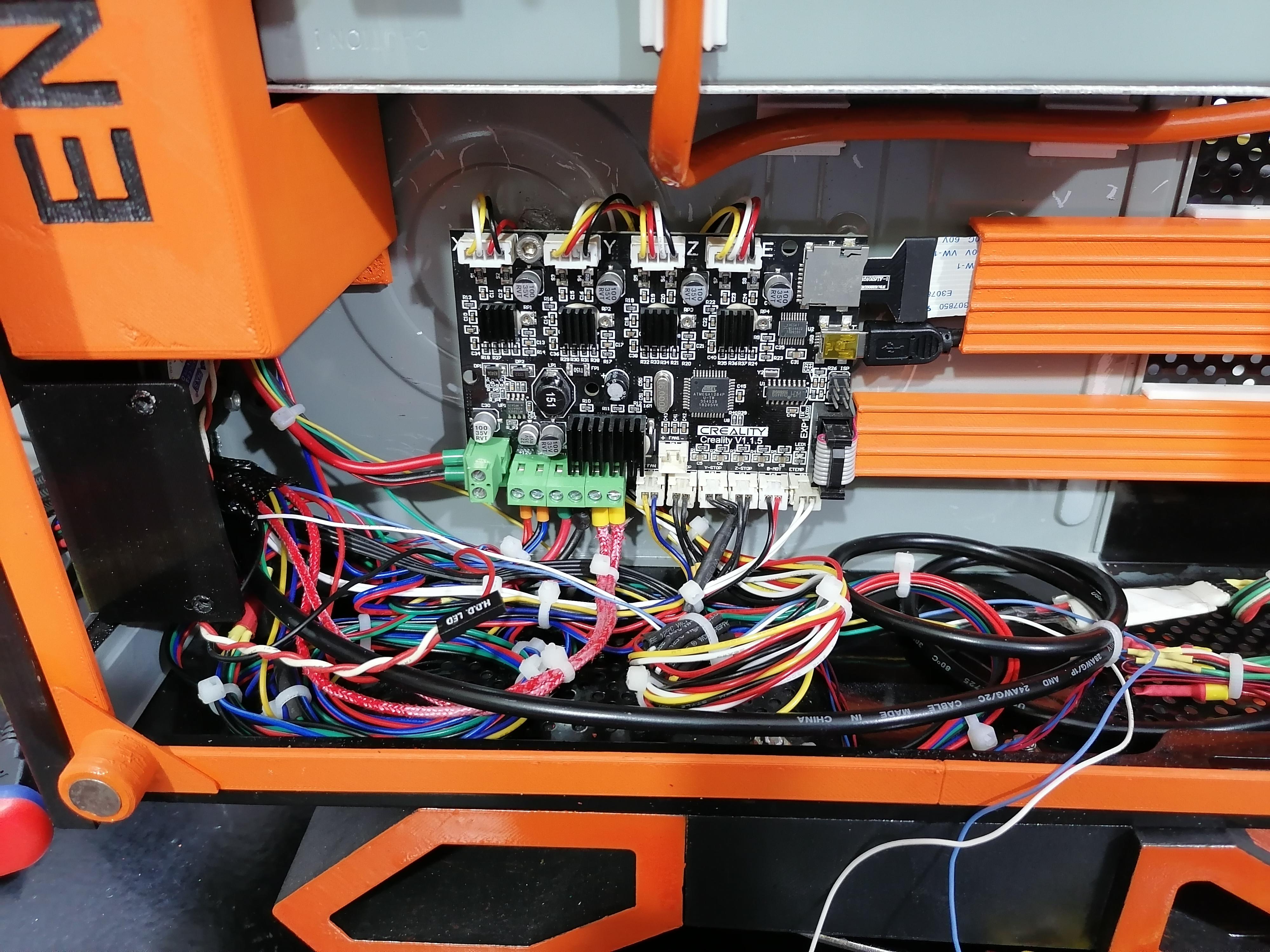
Complete All Wire Harness


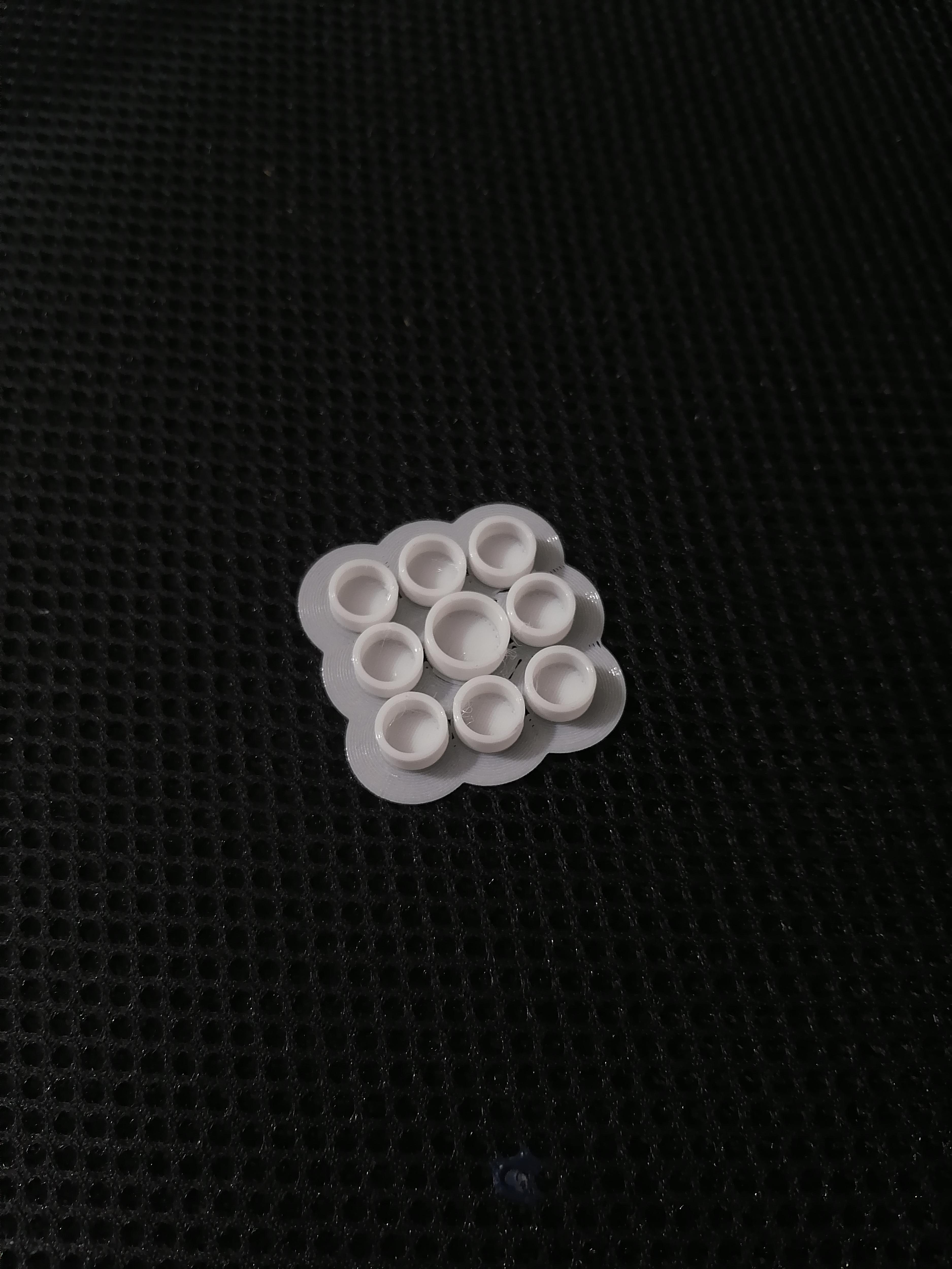
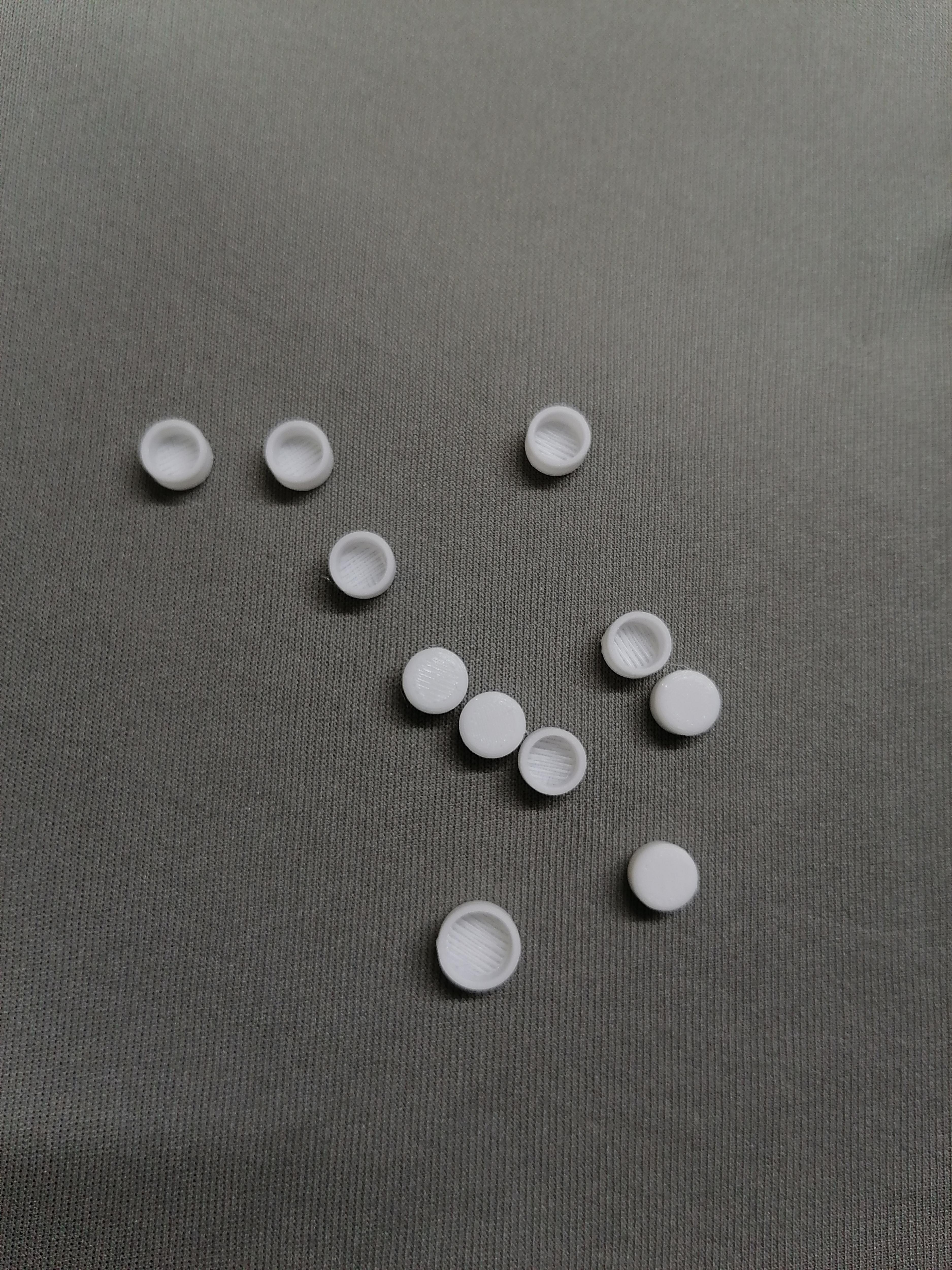
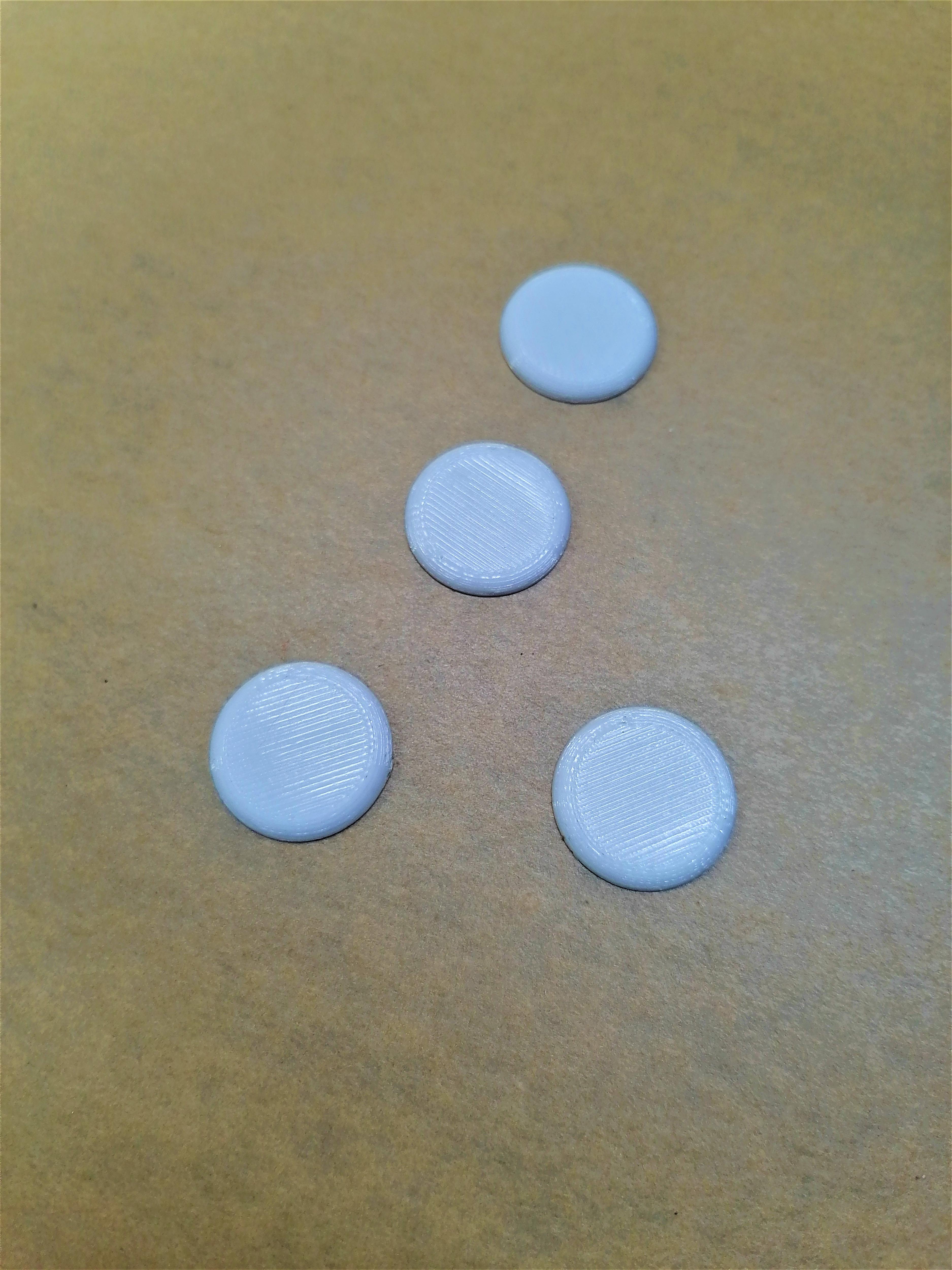
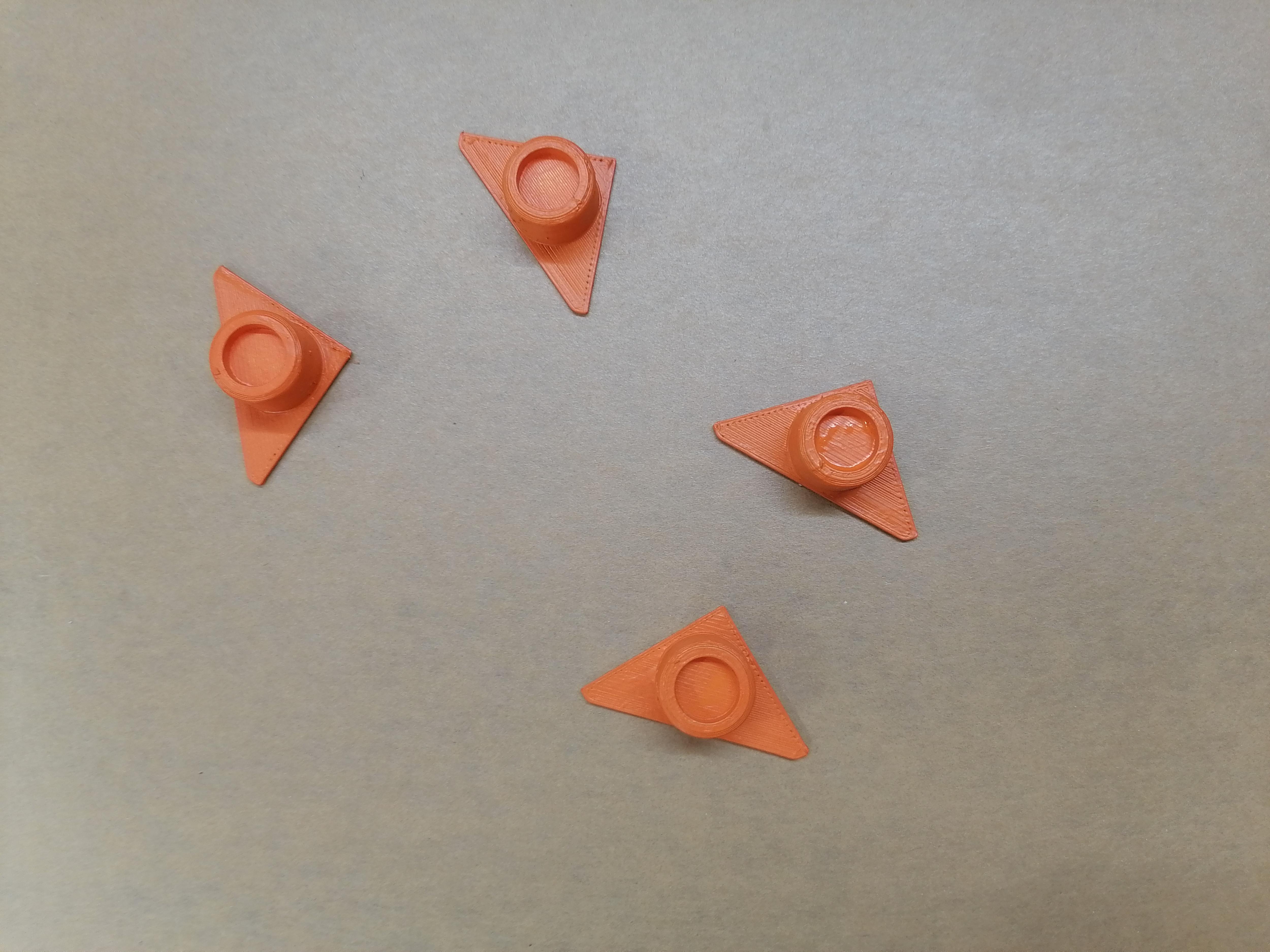
Attaching Corner Magnets to Hold Transparent Acrylic Sheet
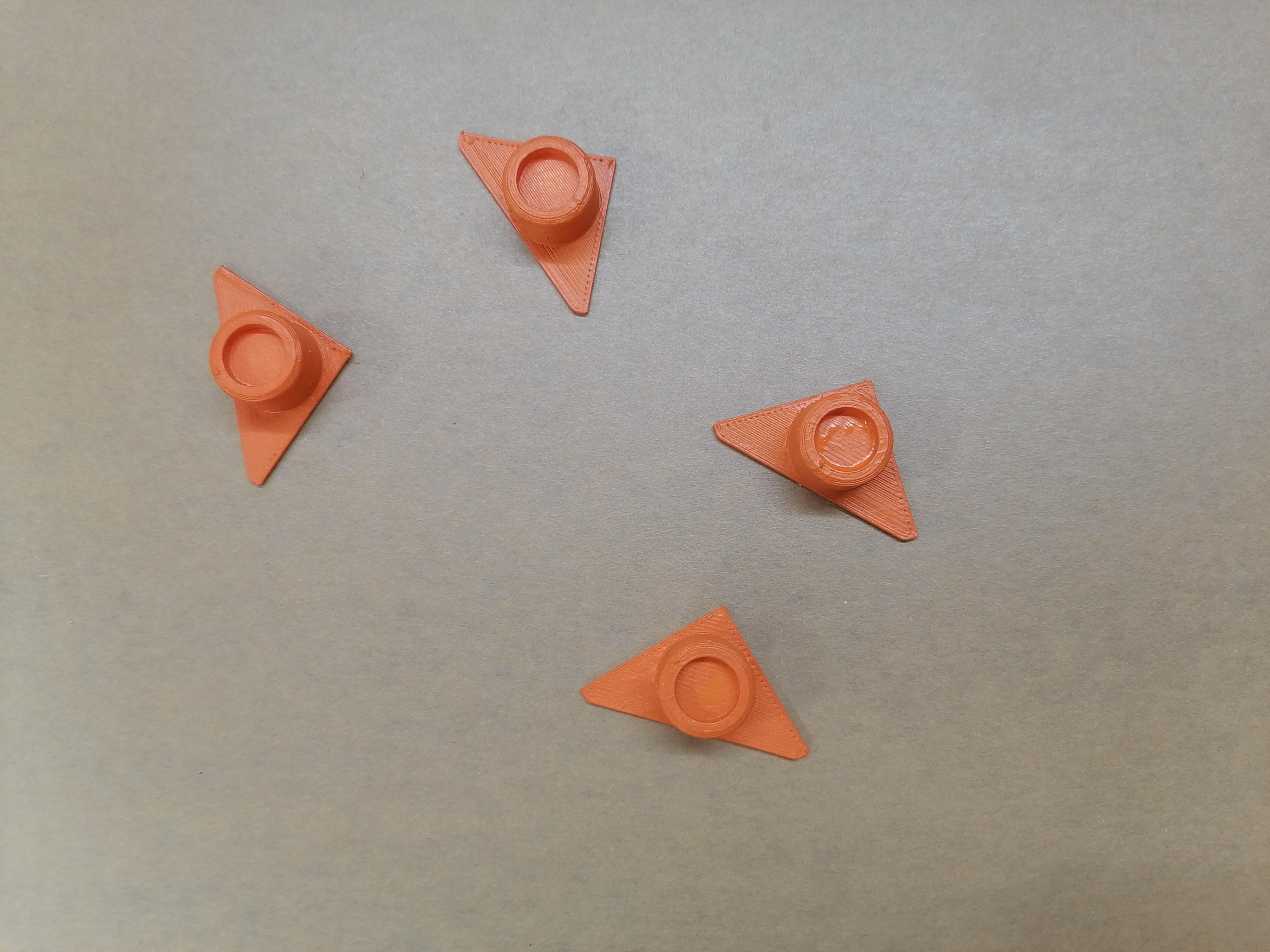
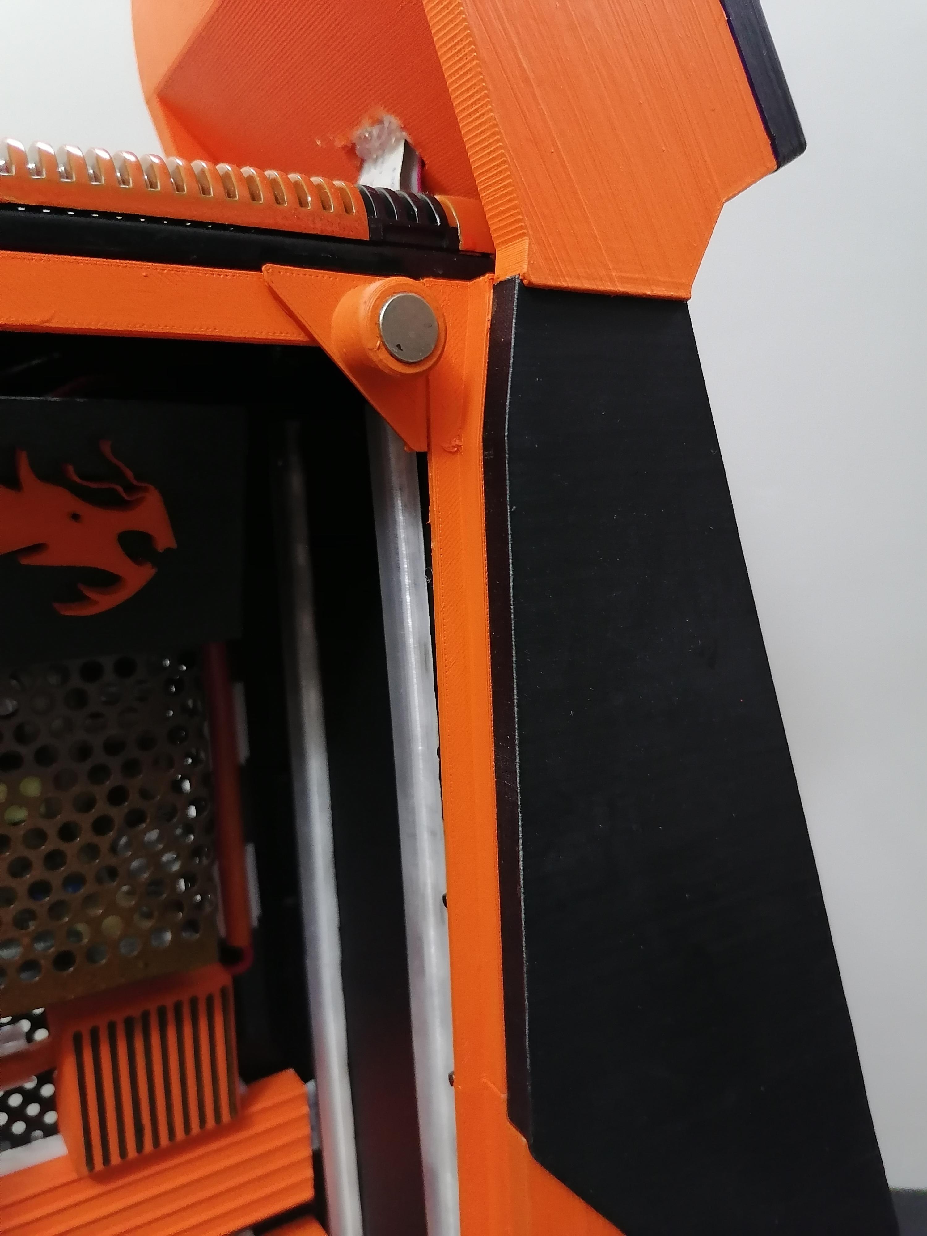


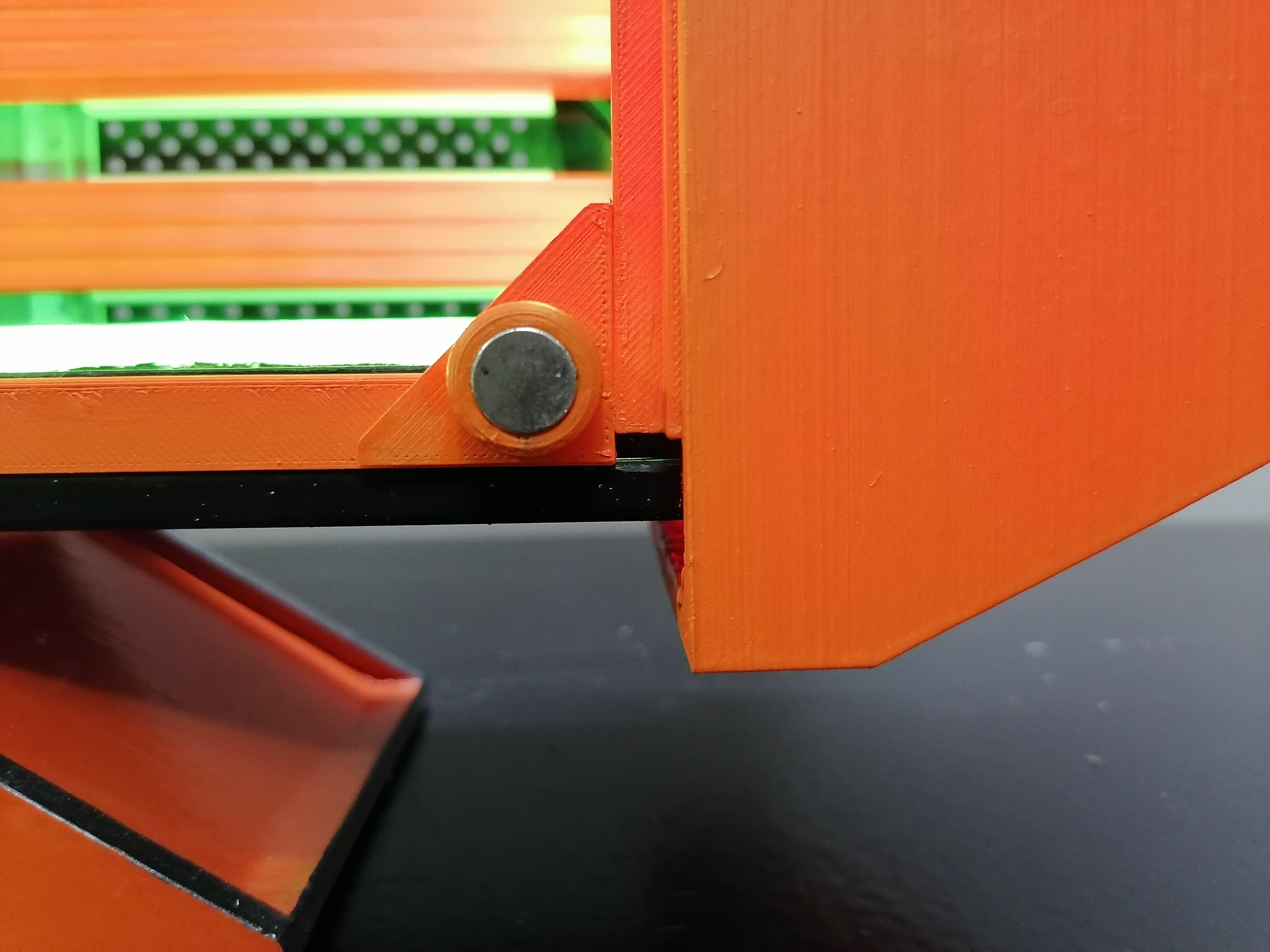

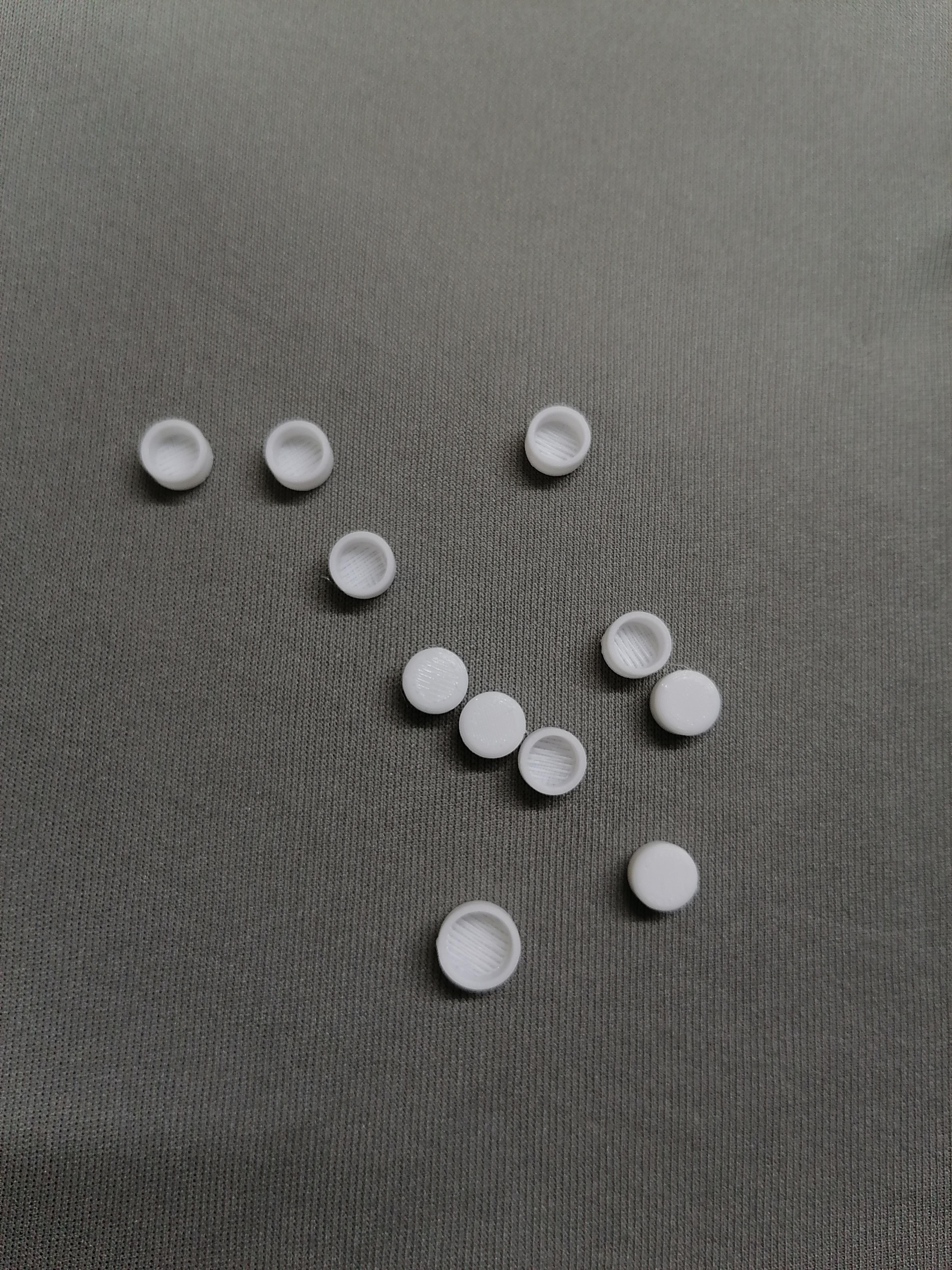
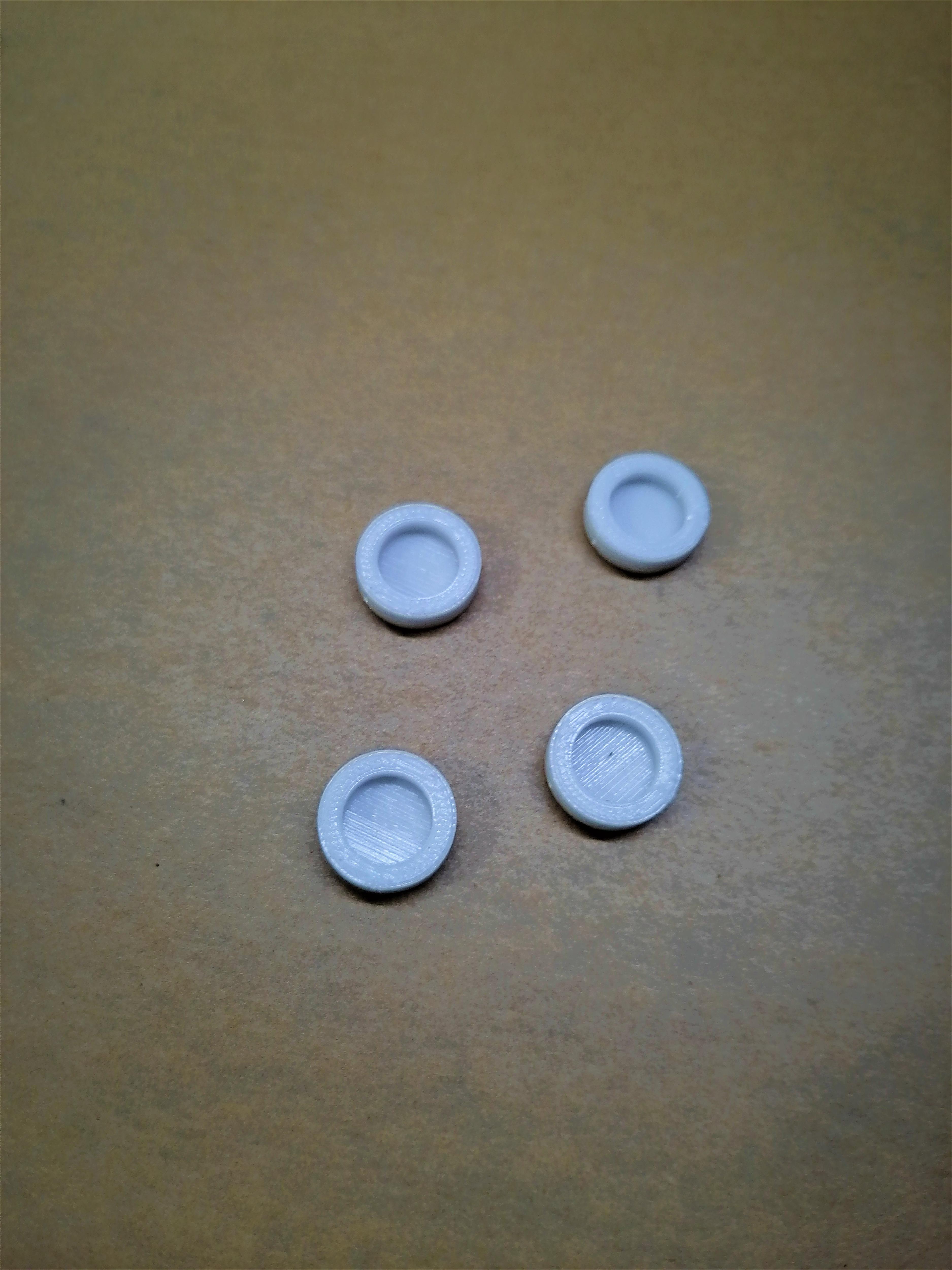


Insert Magnets in the given parts and glue it at shown in above image. The circular Magnets will be attached on Acrylic sheet and to hide magnet I use big circle parts and stick on front side of acrylic.
Note: Refer image for more understanding.
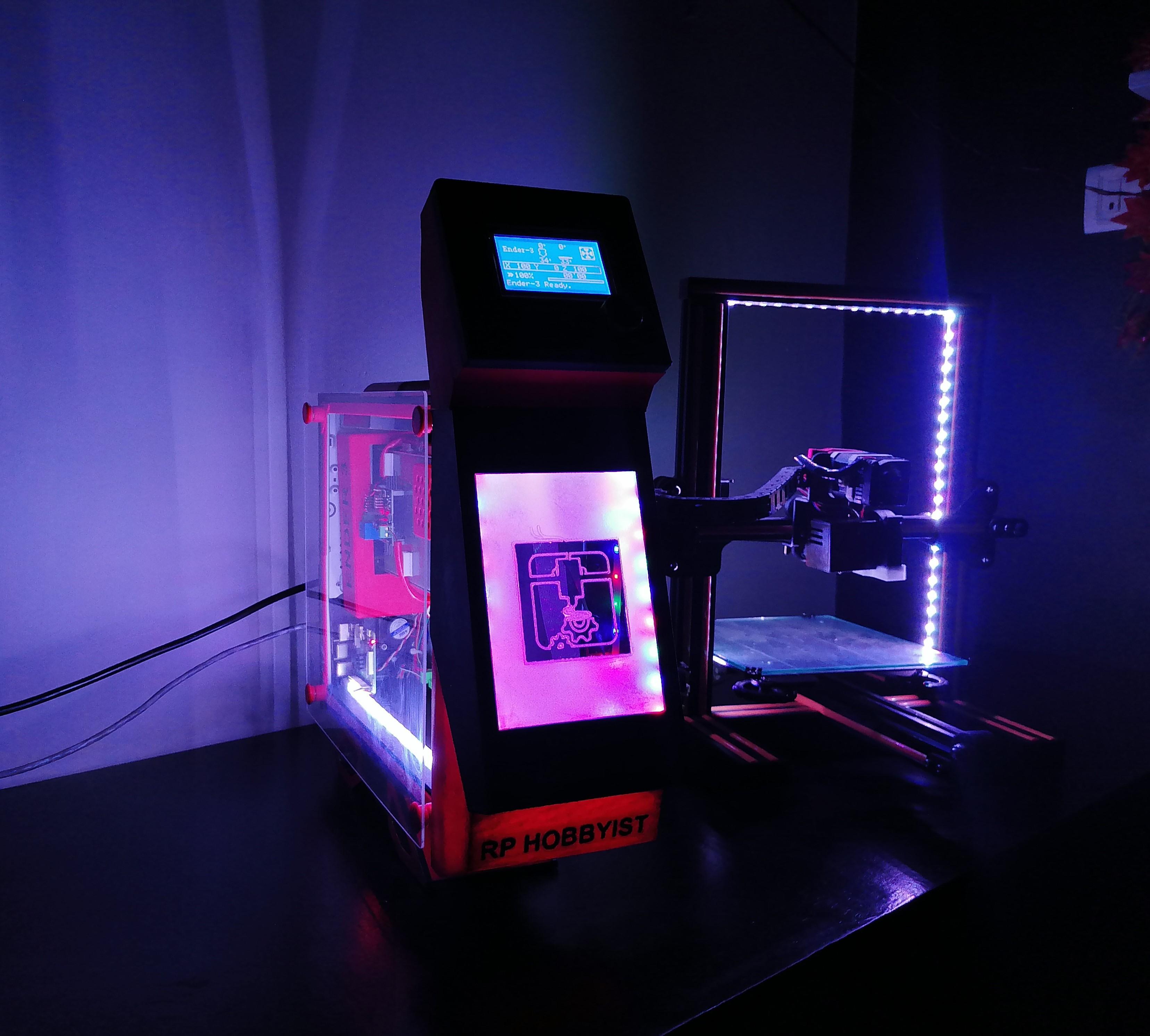
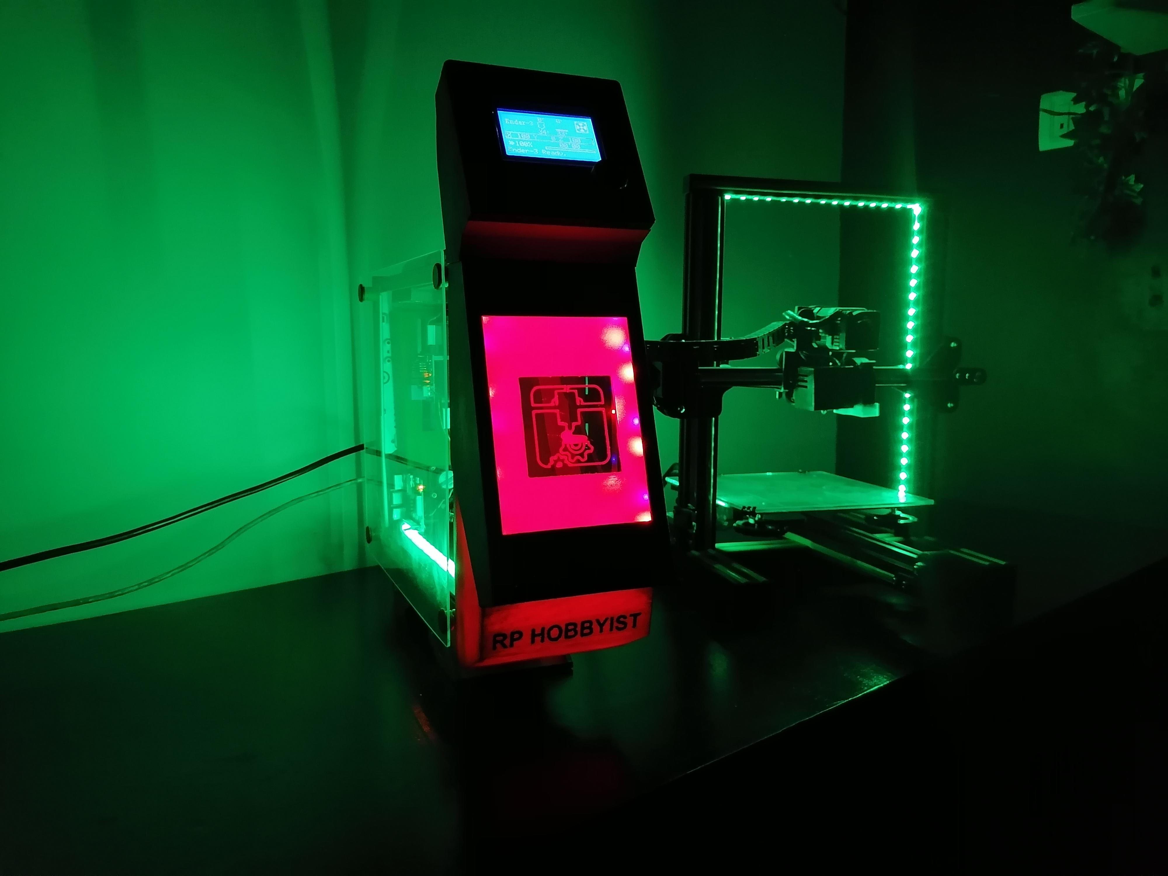
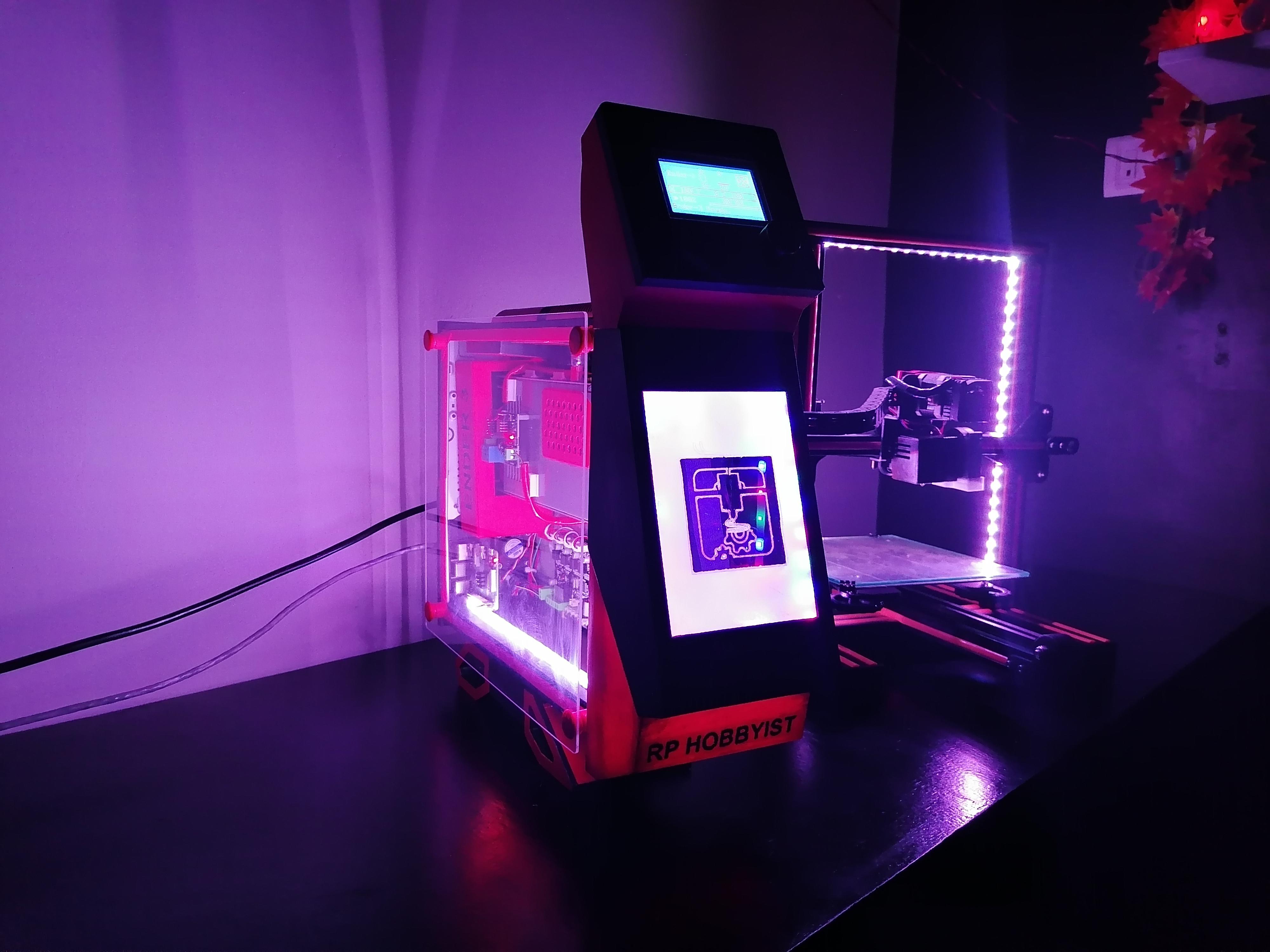
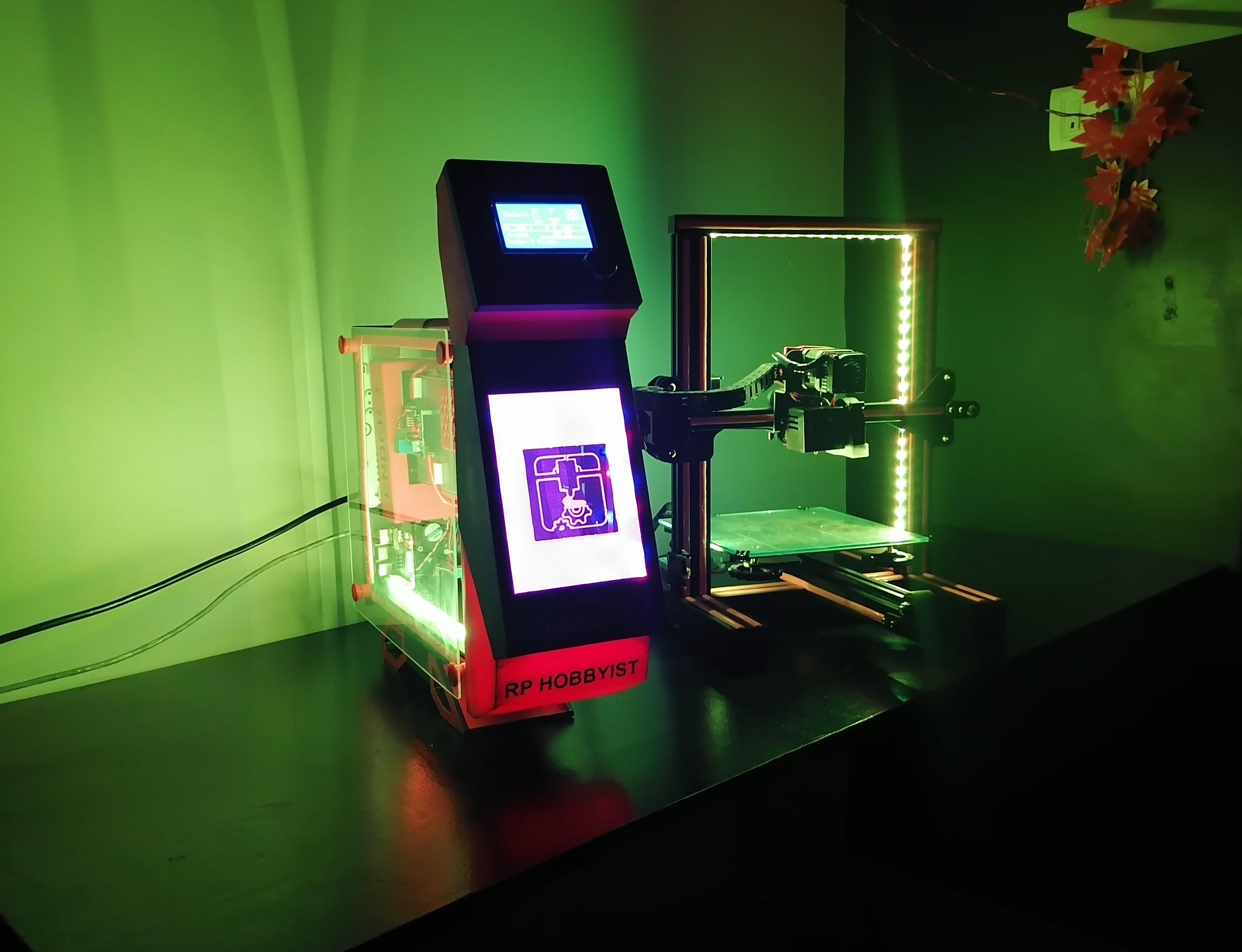
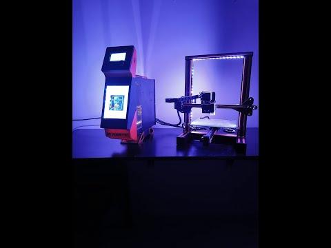
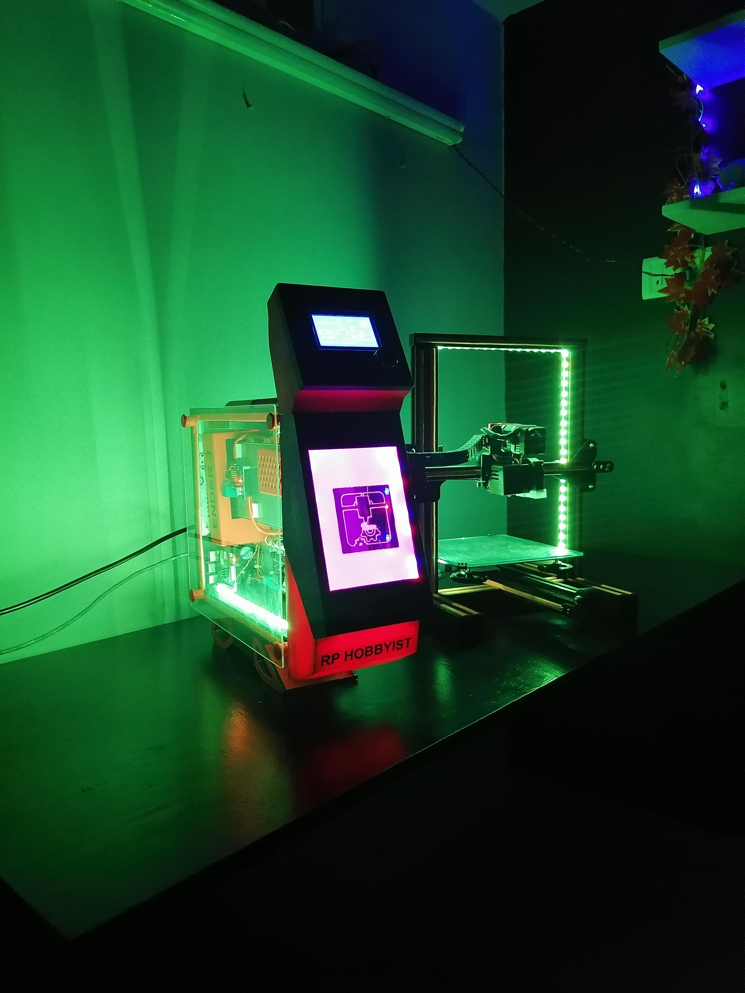
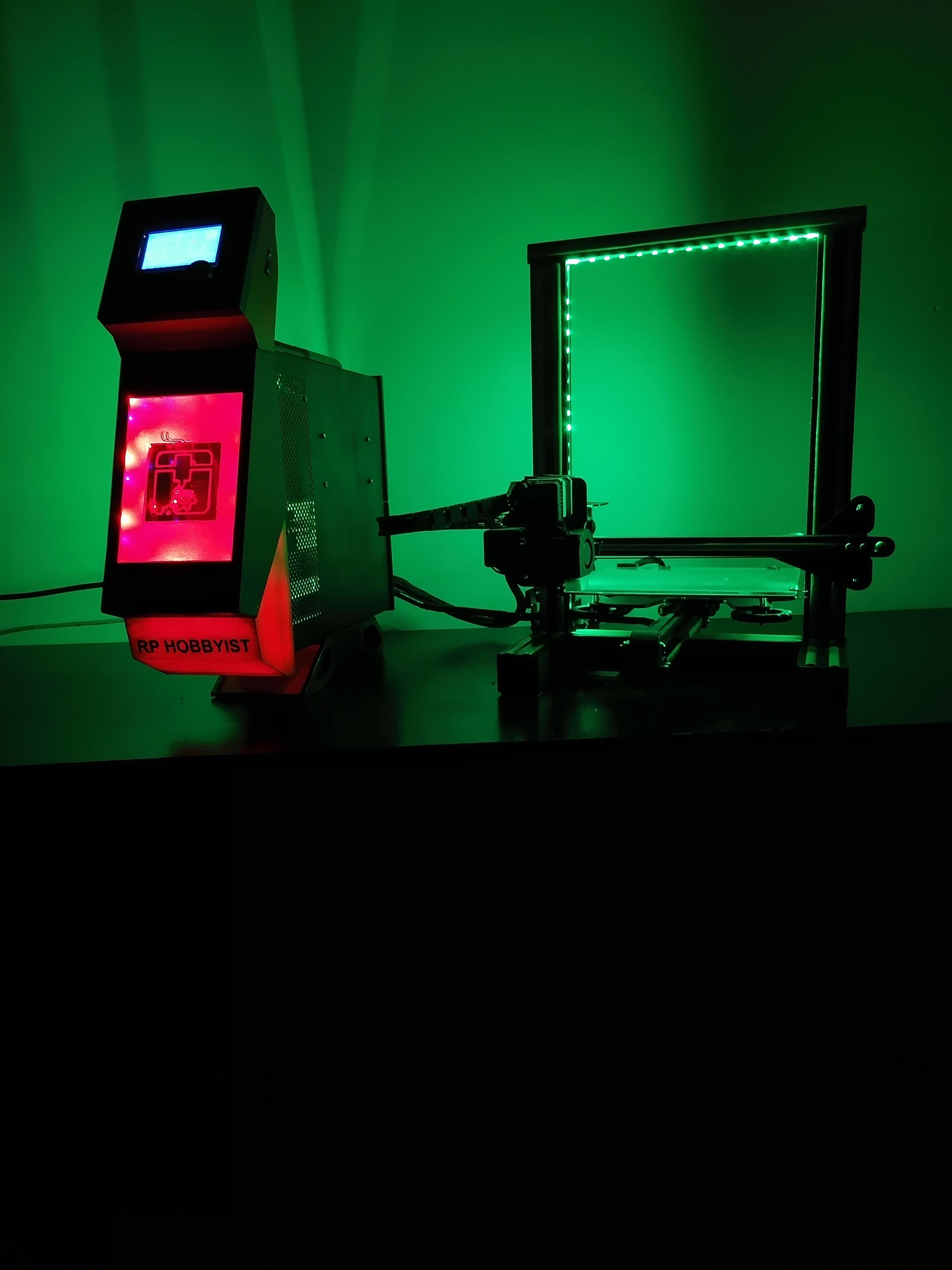
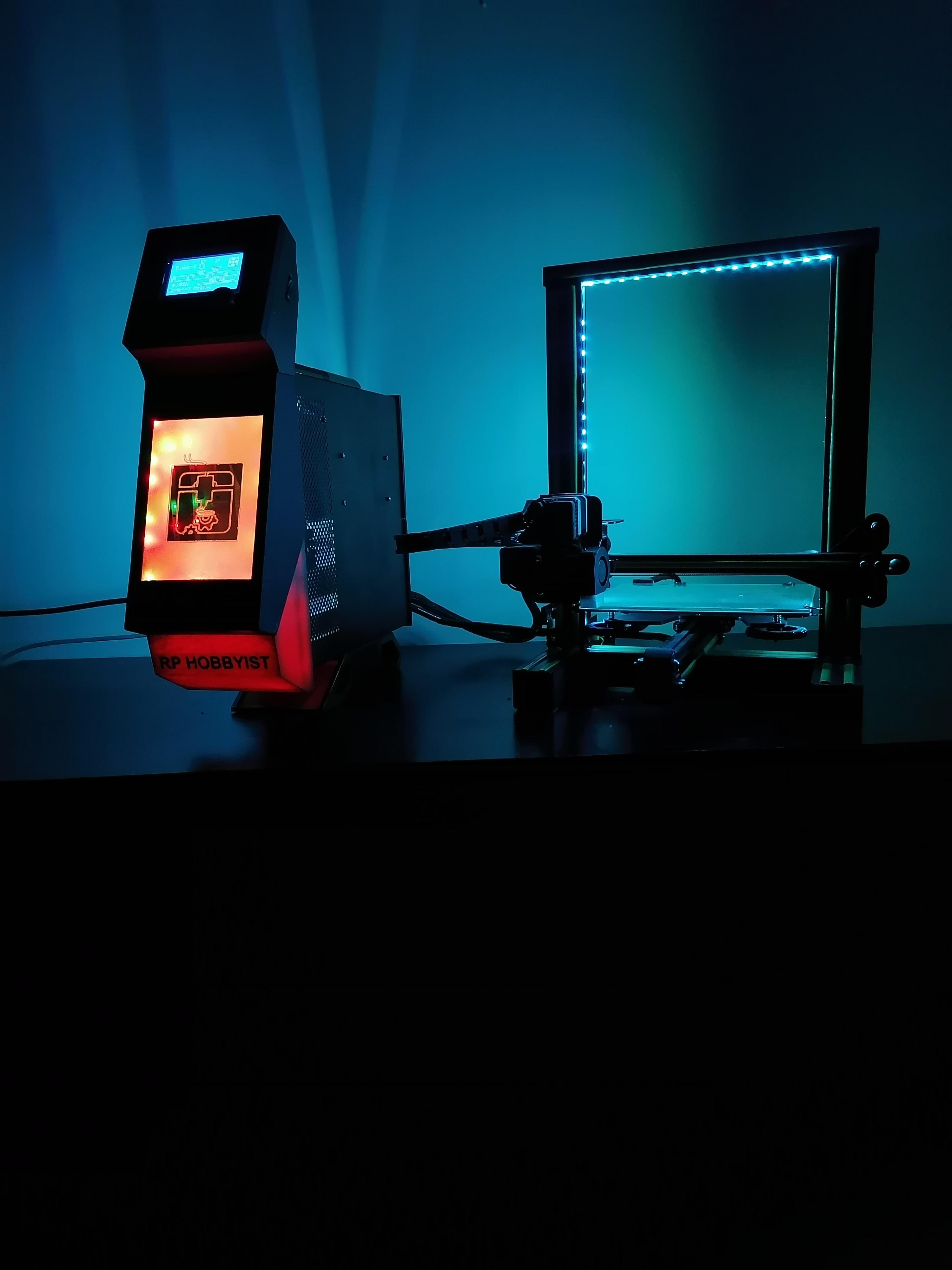
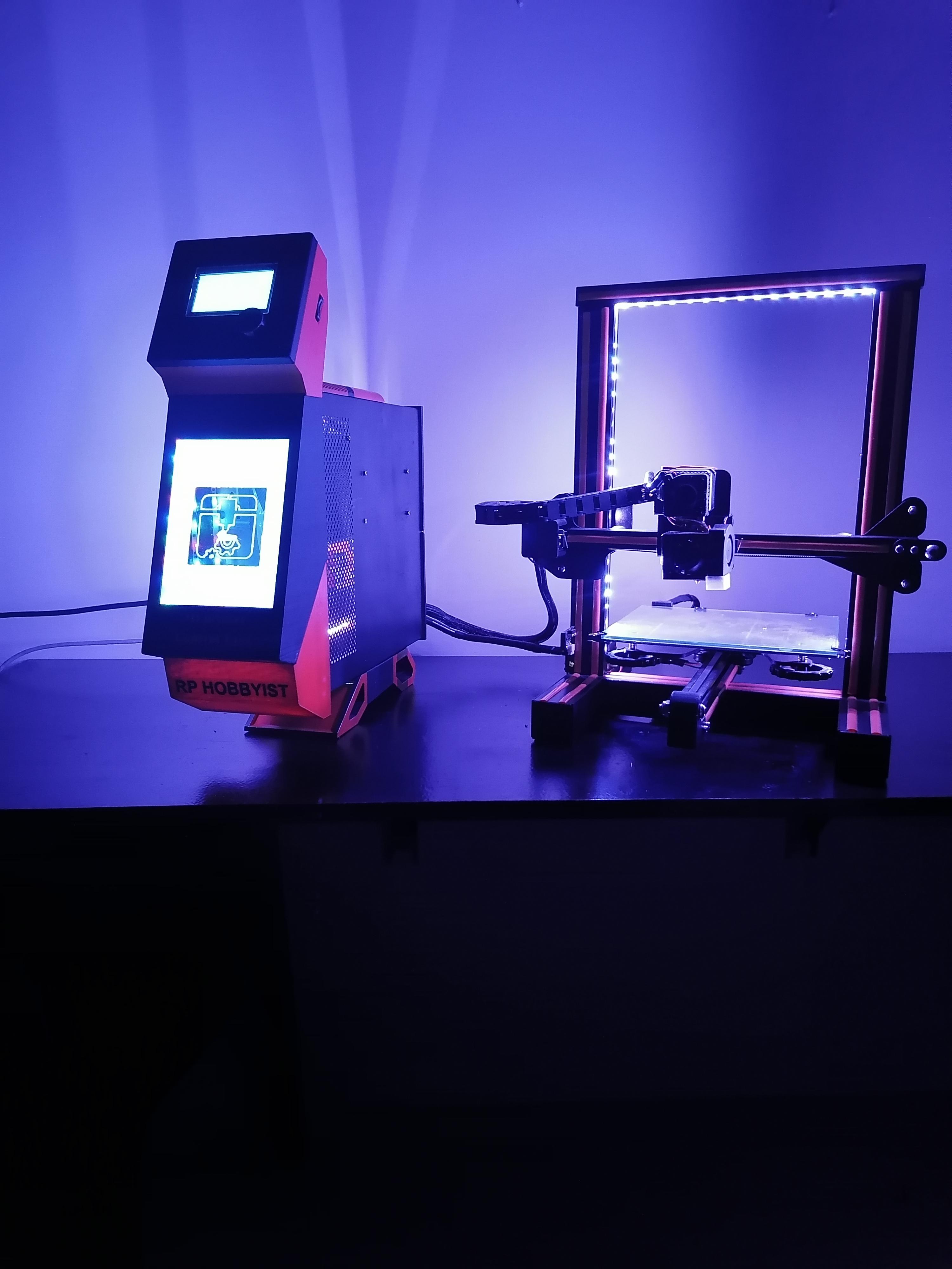
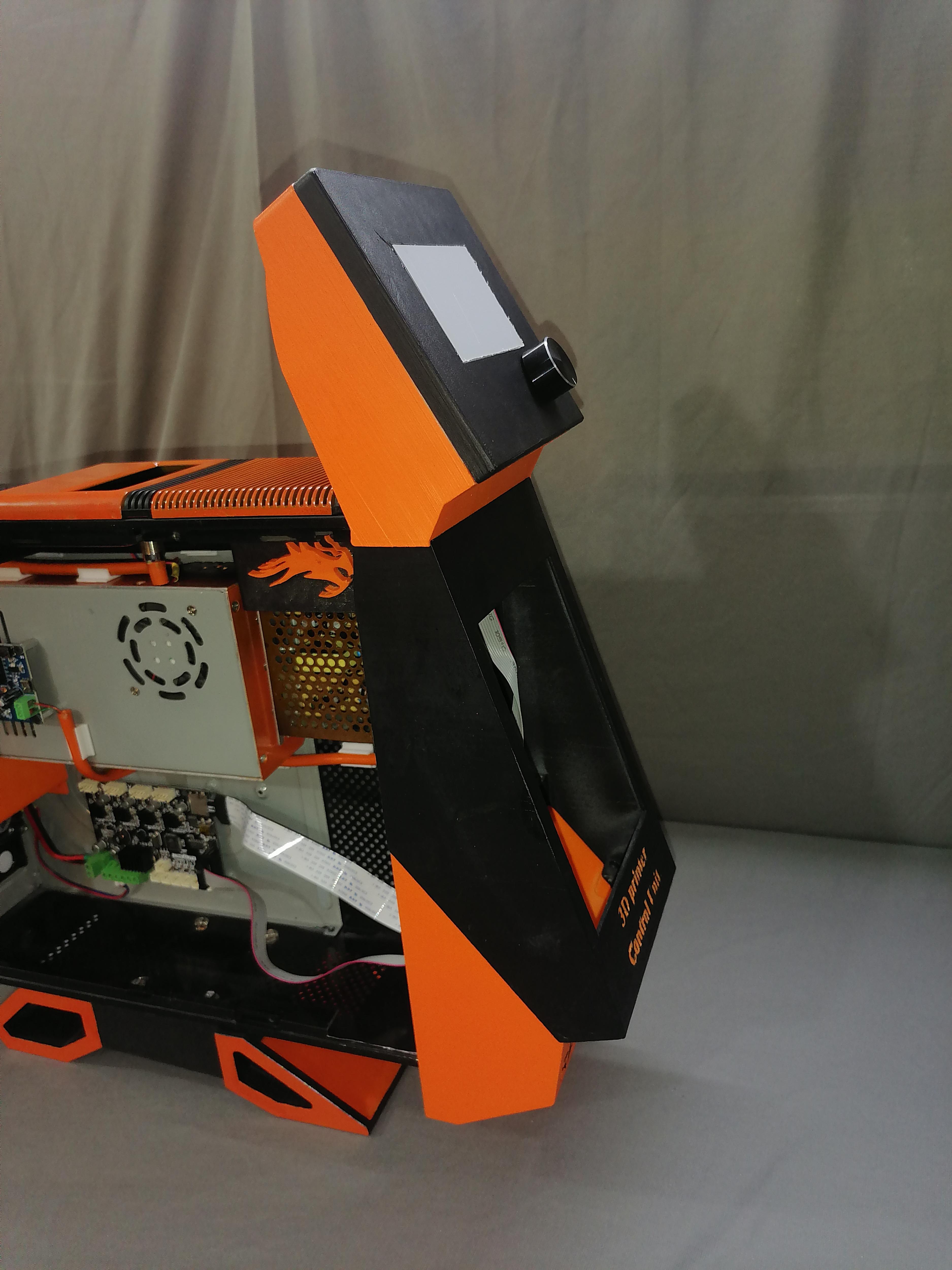
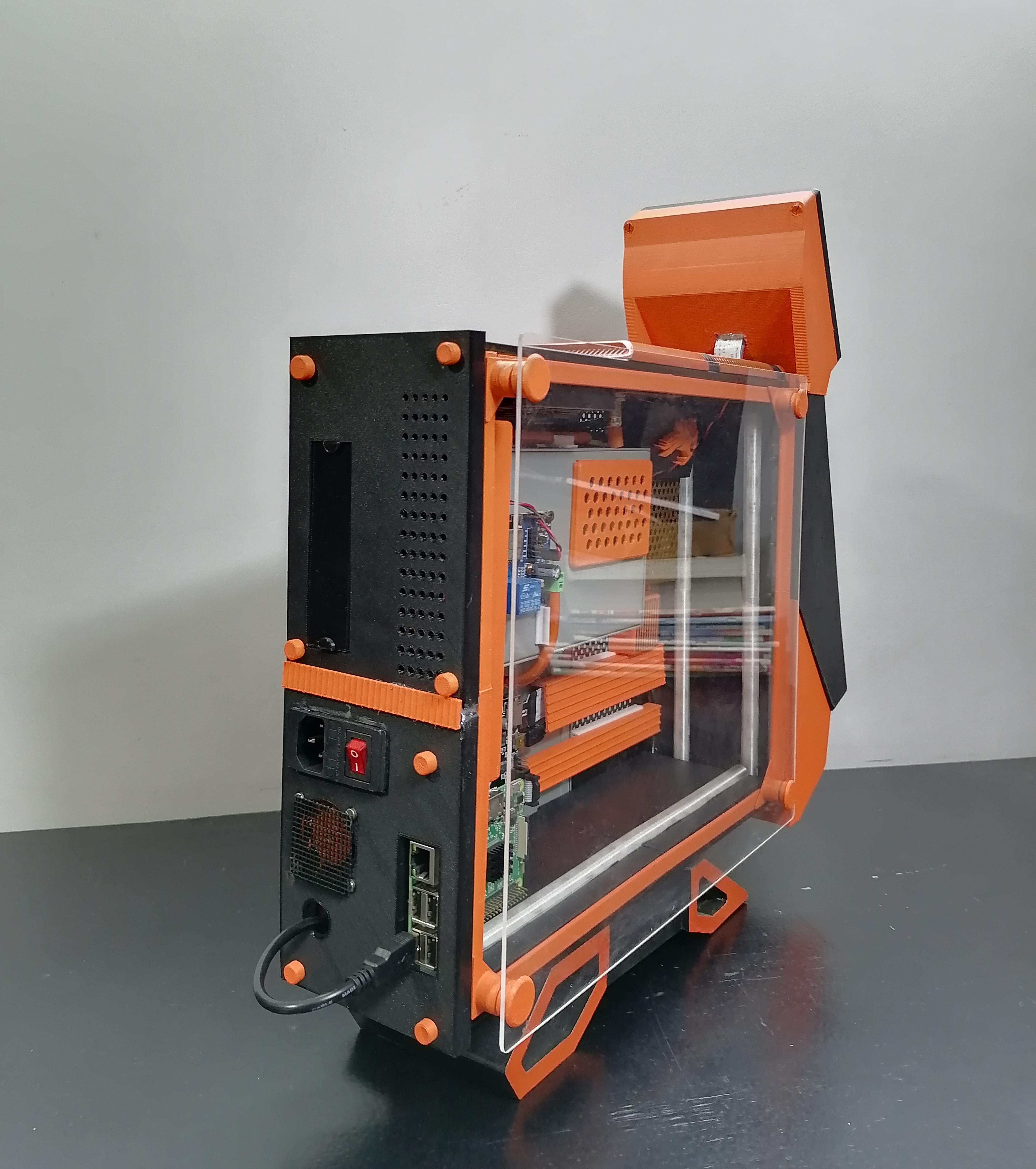
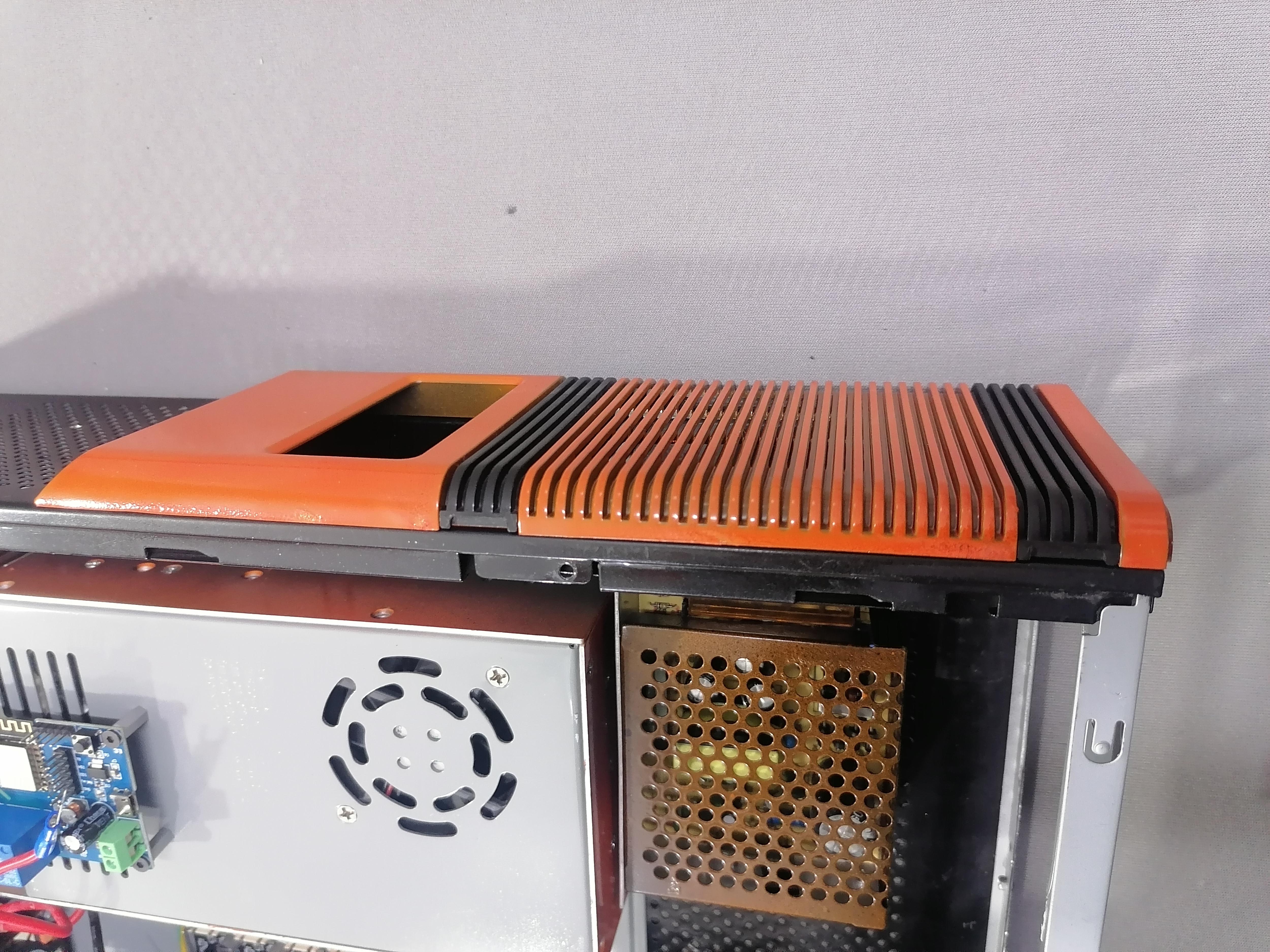
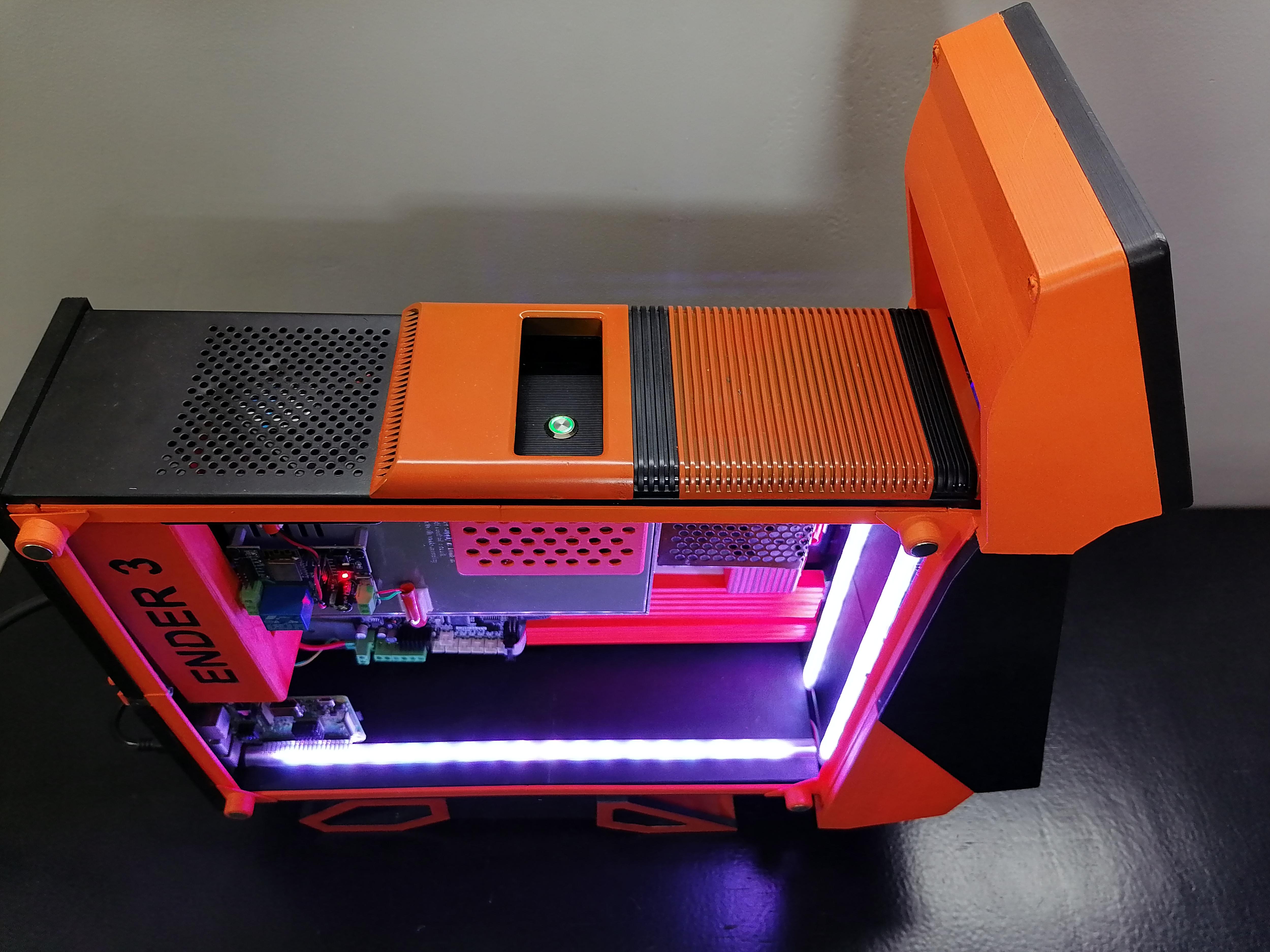
Final Look.....