COVID-19 Human Detector Using Tinkercad Circuits
by ankitbirla in Circuits > Arduino
11051 Views, 13 Favorites, 0 Comments
COVID-19 Human Detector Using Tinkercad Circuits
.png)
Introduction: Are you also bored in this lockdown time because you don’t have any component to make or create something which is useful for our society in this pandemic time. So, don’t worry Tinkercad is everywhere which gives you the facility is free to create or test any project or circuit.
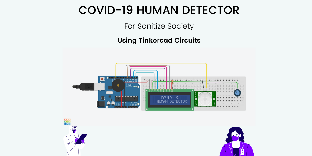
So, in this project we are creating a COVID-19 Human Detector using Arduino, 16x2 LCD, Potentiometer, PIR Sensor & Buzzer in Tinkercad. The PIR or Passive Infrared Sensor is a digital sensor which detects the movement of infrared lights from Humans & Animals. If any infrared light is detected by the PIR sensor then the buzzer will beep and it shows the status on LCD that there is any human or not.
So, by using this circuit you can create an automated sanitize chamber or a machine to detect that there is any human or not from 7-8 m of distance. So, let’s get started by gathering the components for this project in Tinkercad.
Components and Tool
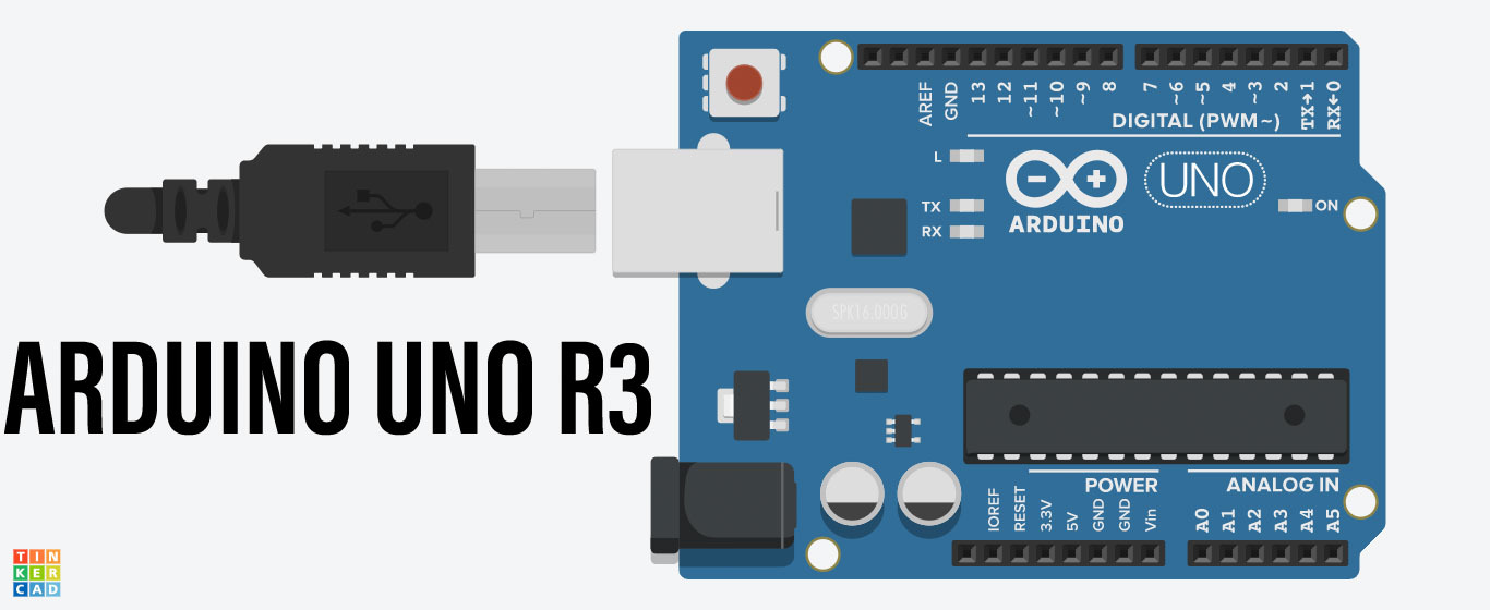
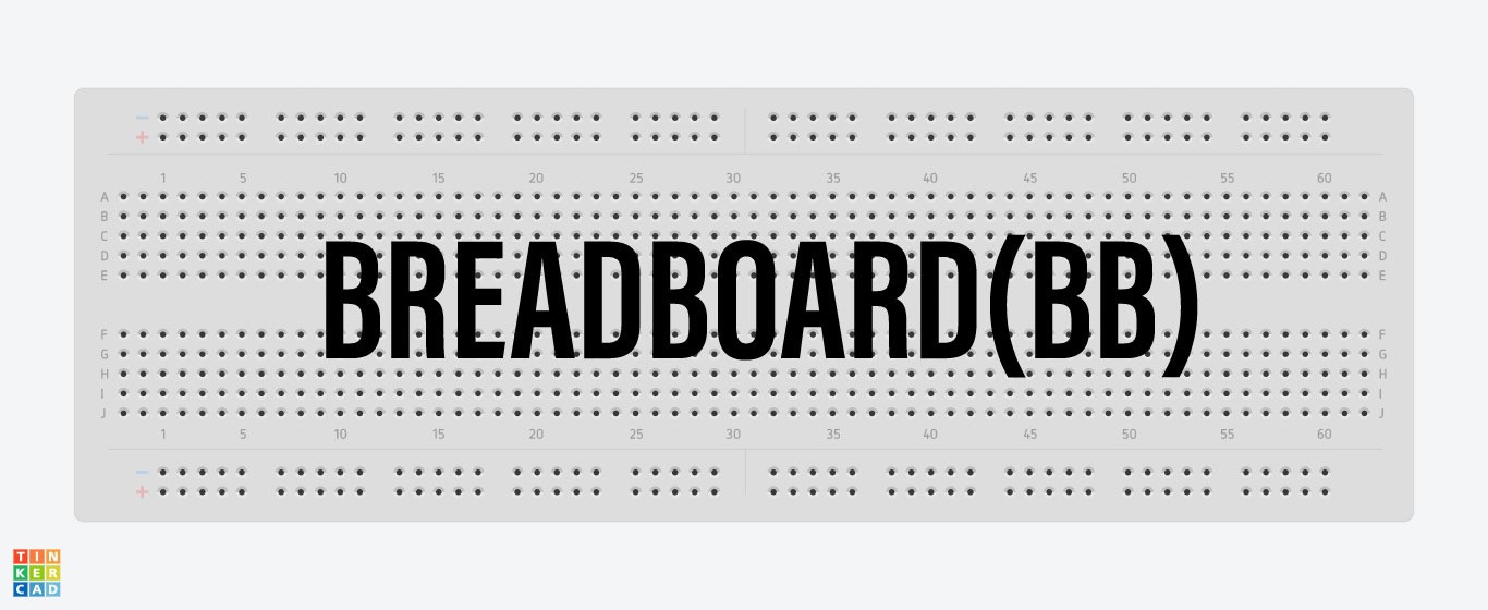
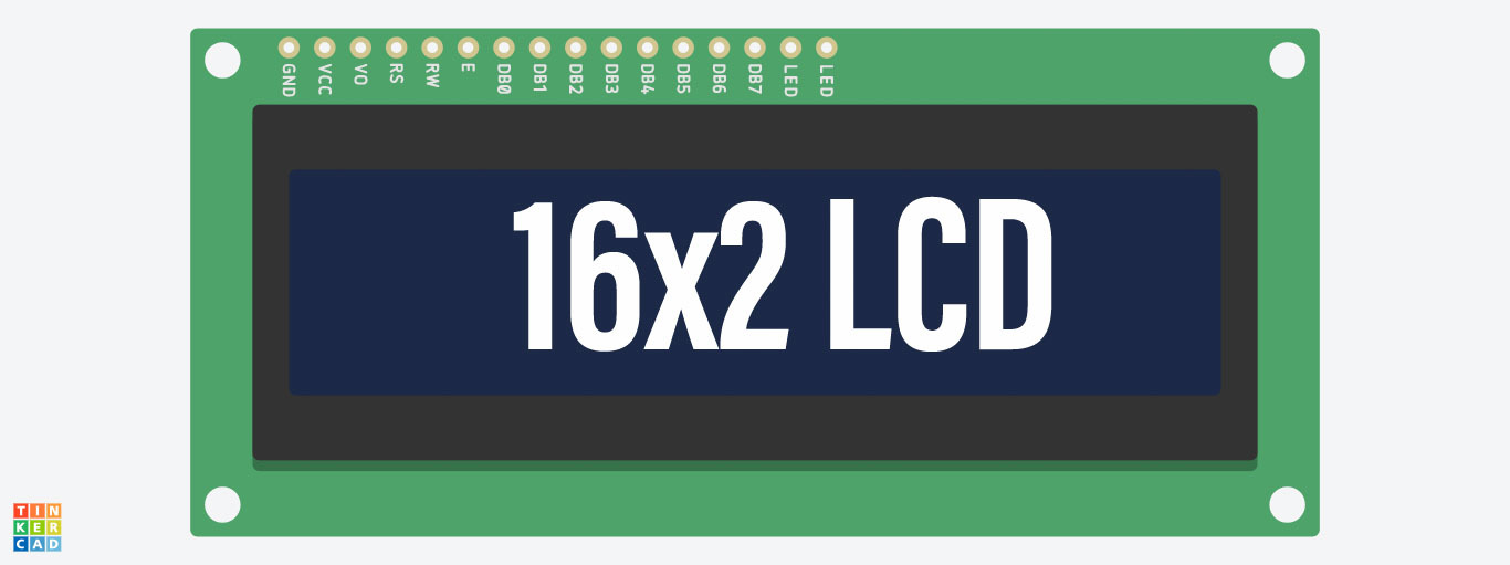

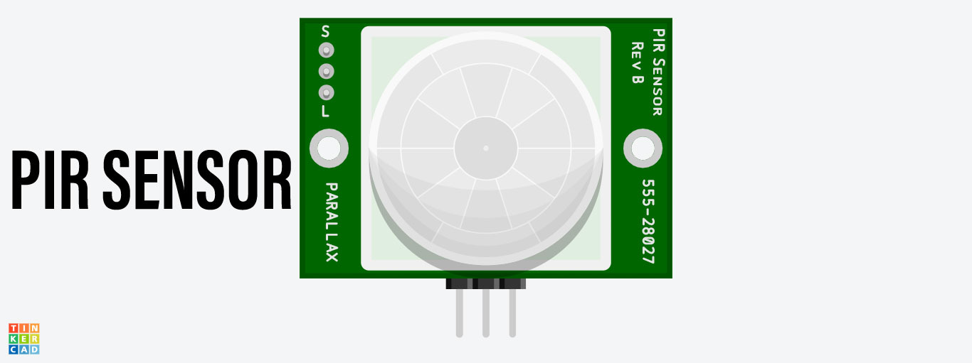


You will need the following components and tools for creating this COVID-19 Human Detector.
Components
- Arduino UNO R3,
- Breadboard (BB),
- 16x2 LCD,
- 1k ohm Resistor,
- 250 k ohm Potentiometer,
- PIR Sensor (HC- SR501),
- Buzzer.
Tools
Setting Up the Circuit (Give Power to the BreadBoard From Arduino)
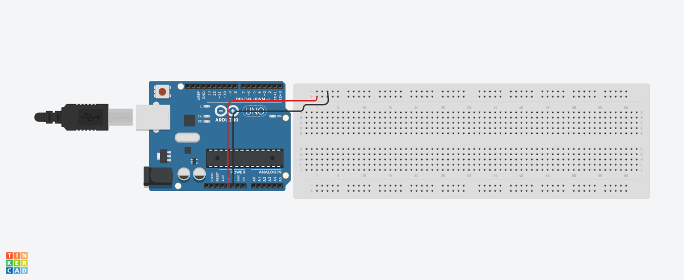
After gathering all the components in Tinkercad this time to wiring the circuit by interfacing with each other.
So, first of all, we are giving a common +5v and GND connection on the breadboard rail as shown in the image.
Interface 16x2 LCD With Arduino
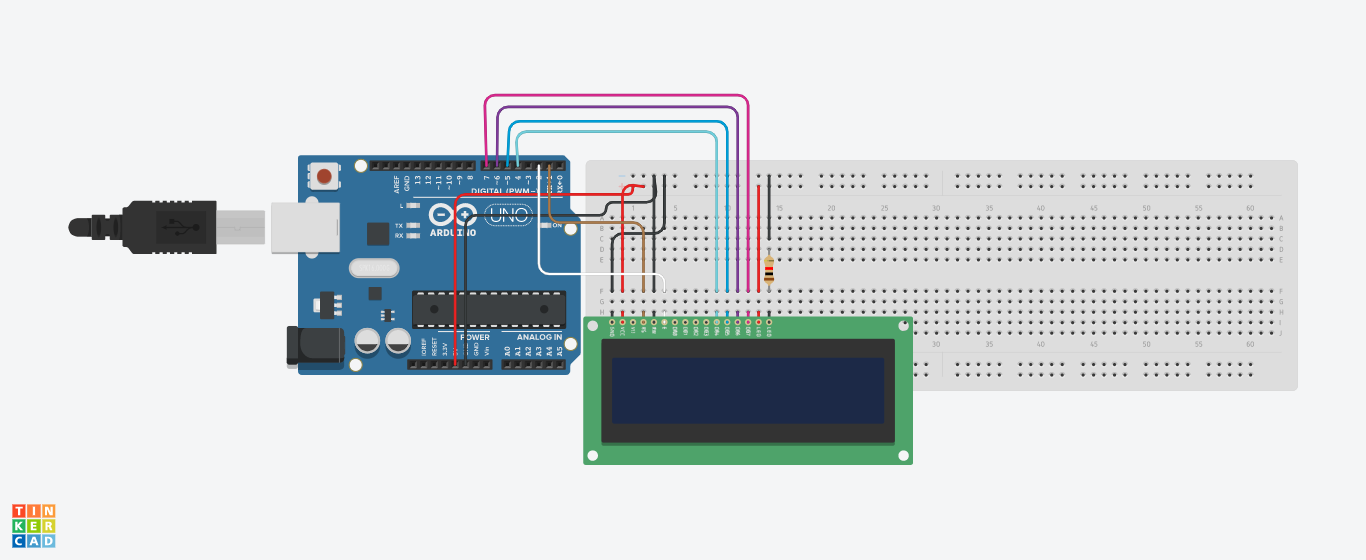
After completing the above step this time to interfacing a 16x2 LCD with Arduino. So, for this follow the following connections and above schematic-
- GND pin (LCD) --> GND rail (Breadboard),
- Power pin (LCD) --> +5v rail (Breadboard),
- LED Cathode pin (LCD) --> GND rail (Breadboard) with 1k ohm resistor,
- LED Anode pin (LCD) --> +5v rail (Breadboard),
- Read/Write pin (LCD) --> GND rail (Breadboard),
- RS pin (LCD) --> Digital pin 1 (Arduino),
- Enable pin (LCD) --> Digital pin 2 (Arduino),
- DB4 (LCD) --> Digital pin 4 (Arduino),
- DB5 (LCD) --> Digital pin 5 (Arduino),
- DB6 (LCD) --> Digital pin 6 (Arduino),
- DB7 (LCD) --> Digital pin 7 (Arduino).
Interface Potentiometer With 16x2 LCD
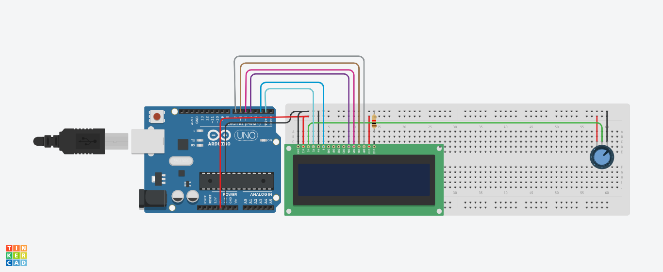
After interfacing LCD with Arduino this time to interfacing potentiometer with LCD for the LCD contrast. So, for this see the following connection with LCD -
- Terminal 1 (Potentiometer) --> +5v rail (Breadboard),
- Terminal 2 (Potentiometer) --> GND rail (Breadboard),
- Wiper pin (Potentiometer) --> Contrast pin (LCD).
Interface PIR Sensor With Arduino
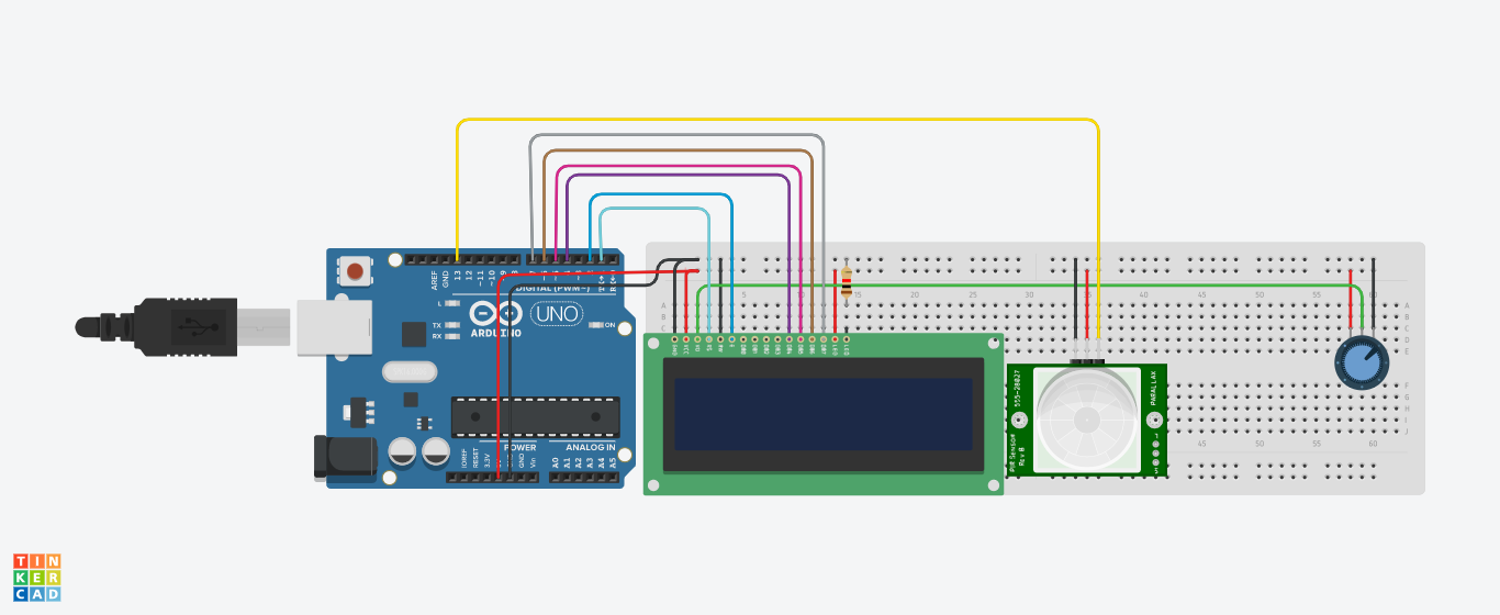
Place your PIR sensor on the breadboard and connect it with Arduino with the following Connections:
- GND pin (PIR) --> GND rail (BreadBoard),
- Power Pin (PIR) --> +5v rail (BreadBoard),
- Signal Pin (PIR) --> Digital pin 13 (Arduino).
Interface Buzzer With Arduino and Complete Your Circuit
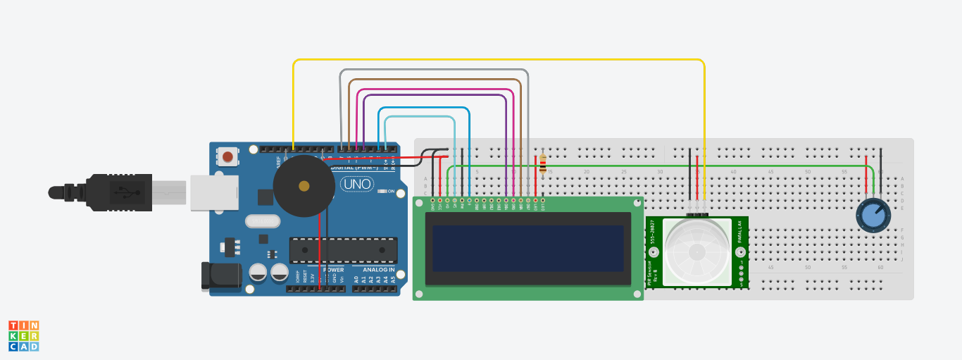
When the human detected so for this, we are using a buzzer for beeping. Interface the buzzer using the following connection
- Positive pin (Buzzer) --> Digital pin 9 (Arduino),
- Negative Pin (Buzzer) --> Ground pin (Arduino).
After interfacing all the components your circuit has been completed for Covid-19 Human Detector as shown in the above image
Also See This Video for Setting Up the Circuit

Writing the Code (Include the Required Libraries)
Now, we will write our COVID-19 Human Detector Code. So, in this lesson, you will learn to write code that connects the LCD, PIR sensor, Buzzer and Arduino with each other
So, first of all, in our program, we will include the required libraries. So, here we are importing the LCD library with the following command
#include <LiquidCrystal.h>
Create a LCD Object
After that create an LCD object using LiquidCrystal() function to define the RS, EN, D4, D5, D6, D7 pin no. The code is following for defining the pins
LiquidCrystal lcd (1,2,4,5,6,7);
Define the Global Variables
So, after importing the required libraries and creating the object next step to define all global variables for sensor and buzzer with the following code
int pir_sensor =13;
int pir_reader;
int buzzer = 9;
Configure the Void Setup Function ()
In void setup function we define only those functions which we want to execute only one time when the program is started. So in the void setup, we are writing the following lines of code
pinMode(13,INPUT); // For set the PIR signal pin as input mode
pinMode(buzzer,OUTPUT); // For set the Buzzer pin as OUTPUT mode
lcd.begin(16,2); //Start the 16x2 LCD
lcd.setCursor(4,0); // Set the LCD Cursor using lcd.setCursor
lcd.print("COVID-19"); //Print the message on LCD
lcd.setCursor(2,1); //Again set the LCD cursor
lcd.print("HUMAN DETECTOR"); //Again print the another message on different line
delay(2000); //Set the delay
lcd.clear(); // clear the LCD
Configure the Void Loop Function:
This is a loop function of Arduino where we define all the functions and actions which we want to run in a loop. So, in this function, we write the following lines of code
pir_reader = digitalRead(pir_sensor); // Read the pir sensor using digitalRead function
if (pir_reader ==1){ //Use the if – else condition to trigger the action when the input is high
digitalWrite(buzzer,HIGH); //Set the pin HIGH of Buzze
lcd.setCursor(4,0); //Set the cursor of LCD
lcd.print("There is"); //Print the message on LCD
lcd.clear(); //Clear the LCD
lcd.setCursor(4,1); //Set the cursor of LCD
lcd.print(" Human"); //Print the message on LCD
}
else{ //use the else condition
digitalWrite(buzzer,LOW); //Set the pin low of Buzzer
lcd.clear(); //Clear the LCD
lcd.setCursor(4,0); //Set the cursor of LCD
lcd.print("There is"); //Print the message on LCD
lcd.setCursor(4,1); //Set the cursor of LCD
lcd.print("No Human"); //Print the message on LCD
delay(500); //Give a delay
Complete Code
Here is the complete code of COVID-19 Human Detector.
Downloads
Test the Circuit
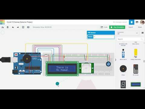
Now test the circuit of Covid-19 Human Detector by click on Start Simulation Button. See the above video.
Some Important points about this Circuit in Real World:
- After powering it will take a maximum of 60 seconds for initialization,
- This will take 5-6 seconds for reading another entry,
- In the sunniest area, this sensor will not work properly,
- You can increase/decrease the sensitivity and time by using its inbuilt pots.
Other Projects by Using This Circuit:
The other project ideas you can make by using only this COVID-19 Human Detector but with some modification of code:
- Automated Sanitize Chamber,
- Thief Detector.
So, think about these above projects and make your own.
Review
So, in this COVID-19 Human Detector project, you used a PIR sensor, Buzzer, a 16x2 LCD with the potentiometer, a 1k ohm resistor, Arduino, and Tinkercad tool. You also learned to interface different components with each other.