CONE LAMP With XIAO
.gif)


Hello everyone, and here's something flashy: a cone-shaped RGB Lamp built from scratch using custom 3D-printed parts and basic electronics, which includes a WS2812 RGB LED and a Seeed XIAO M0 MCU.
The whole setup is powered by a single 3.7V 2900mAh Li-ion cell; the RGB LEDs and XIAO require 5V for operation, so there's a power management IC connected to the Li-ion cell to boost its 3.7V to a stable 5V and also charge the battery properly.
This Instructables is about how this Lamp Project was built and how you can make it in a few easy steps.
Let's get started.
Supplies
Following were the materials used in this built-
- Custom PCBs provided by Seeed Studio
- Seeed XIAO MO Dev Board
- WS2812 LEDs
- Potentiometer
- Li-Ion Cell 3.7V–2200mAh
- IP5306 IC
- 1uf CAP
- 10K Resistor
- 1uH Inductor
- Female Header Pins
- DC Barrel Jack
- Rocker Switch
- 3D-printed parts
Design


3D Design of this CONE LAM consists mainly of two parts, the base and the cone diffuser.
The base of this Lamp will house the Battery and electronics and also contain a Knob for the potentiometer; this knob will change the HUE of the lamp. Additionally, the base contains the LED Holder, which is a square pillar or a pipe-like structure that is used to hold the LED PCB inside the Cone diffuser area.
The whole model was modeled in Fusion 360 and 3D Printed using Yellow PLA and white PLA.
PCB Design


The Power Board and the RGB LED Board are the two different boards that make up PCB Design.
The IP5306, a Power Management IC that is commonly used in power bank-related applications where we have a 3.7V Li-ion cell and need to boost its voltage to a stable 5V for XYZ stuff—in this example, the XIAO M0 MCU and LEDs—makes up the Power Board, a minimal Circuit.
The XIAO M0 MCU is also installed on the power board, and two headers are connected to its 5V, D0, D1, and GND pins via two headers. Potentiometer and LED PCB connections with XIAO are made using these two header pins.
The LED Board consists of a straightforward WS2812 LED configuration connected in pairs of eight, with eight capacitors added to the VCC and GND of each LED, respectively.
A pair of 32 LEDs will be connected by a single digital pin on a total of four of these LED Boards, which will be connected to the XIAO MCU.
Fusion360 was used to develop the PCB Layout for the Power Board and the LED Board, which was then imported into PCB Cad software to create the outline.
Seeed's Fusion PCB Service
.gif)
.gif)
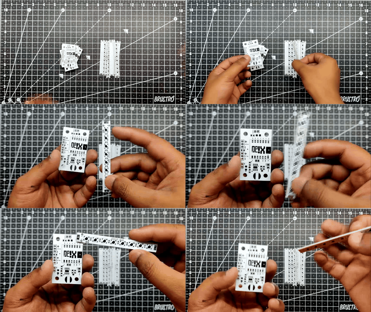
Both the LED PCB and Power Board PCB were sent to SEEED Studio for samples.
Two orders were placed for a White solder mask with Black silkscreen, and the PCBs arrived in less than a week, which was super fast.
The quality was very good considering the price, which was also pretty low.
Seeed Fusion PCB Service offers one-stop prototyping for PCB manufacture and PCB assembly, and as a result, they produce superior quality PCBs and fast turnkey PCBAs within 7 working days.
Seeed Studio Fusion PCB Assembly Service takes care of the entire fabrication process, from Seeed Studio Fusion Agile manufacturing and Hardware Customization to parts sourcing, assembly, and testing services, so you can be sure that they are getting a quality product.
After gauging market interest and verifying a working prototype, Seeed Propagate Service can help you bring the product to market with professional guidance and a strong network of connections.
Next, we prepare for the LED PCB assembly process.
LED PCB Assembly Process
.gif)
.gif)
.gif)
.gif)
This project's PCB assembly process consists of two PCBs, the LED Board and the power board, We first start with the assembly process of the LED Board.
- We begin by applying solder paste to each component pad individually using a solder paste dispensing syringe. We have to use four LED PCBs in this project, so we had to apply solder paste to all four PCBs.
- Next, we pick and place all the components, which include the LED and capacitor, in their proper places using ESD tweezers.
- Following the pick and place process, we place this board on a mini reflow hotplate, which heats the PCB from the bottom up to the solder paste melting temperature.
Testing LED PCB Board
.gif)
In order to test the LED Board, we connect them together according to the given wiring schematic and connect them together with the Xiao MCU using jumper leads.
We programmed the Xiao MCU with Adafruit's Neopixel LED Test sketch, changing the Pin number to D0 and the quantity of LEDs to 32. In order to extend the LED's life, we also reduced the delay time from 500 to 100 or less.
Below is the sketch which was used
#include <Adafruit_NeoPixel.h>
#ifdef __AVR__
#include <avr/power.h>
#endif
// Which pin on the Arduino is connected to the NeoPixels?
// On a Trinket or Gemma we suggest changing this to 1
#define PIN            0
// How many NeoPixels are attached to the Arduino?
#define NUMPIXELS      32
// When we setup the NeoPixel library, we tell it how many pixels, and which pin to use to send signals.
// Note that for older NeoPixel strips you might need to change the third parameter--see the strandtest
// example for more information on possible values.
Adafruit_NeoPixel pixels = Adafruit_NeoPixel(NUMPIXELS, PIN, NEO_GRB + NEO_KHZ800);
int delayval = 100; // delay for half a second
void setup() {
// This is for Trinket 5V 16MHz, you can remove these three lines if you are not using a Trinket
#if defined (__AVR_ATtiny85__)
if (F_CPU == 16000000) clock_prescale_set(clock_div_1);
#endif
// End of trinket special code
pixels.begin(); // This initializes the NeoPixel library.
}
void loop() {
// For a set of NeoPixels the first NeoPixel is 0, second is 1, all the way up to the count of pixels minus one.
for(int i=0;i<NUMPIXELS;i++){
// pixels.Color takes RGB values, from 0,0,0 up to 255,255,255
pixels.setPixelColor(i, pixels.Color(0,150,0)); // Moderately bright green color.
pixels.show(); // This sends the updated pixel color to the hardware.
delay(delayval); // Delay for a period of time (in milliseconds).
}
}
Power Board PCB Assembly Process
.gif)
.gif)
.gif)
.gif)
.gif)
.gif)
- We Now apply solder paste to each component pad individually using a solder paste dispensing syringe.
- Next, we pick and place all the components in their proper places using ESD tweezers.
- Following the pick and place process, we place this board on a mini reflow hotplate, which heats the PCB from the bottom up to the solder paste melting temperature.
- Then we put all of the THT components in their proper places, such as the header pins in the XIAO pads and the battery connector.
- We use soldering iron to solder the Header pin in its place and the PCB Assembly is complete.
Testing Power Board
.gif)
.gif)
.gif)
In addition to connecting a rocker switch to the XIAO Board so that the power board can be turned ON and OFF, we also add a DC Barrel Jack for charging the Li-ion battery.
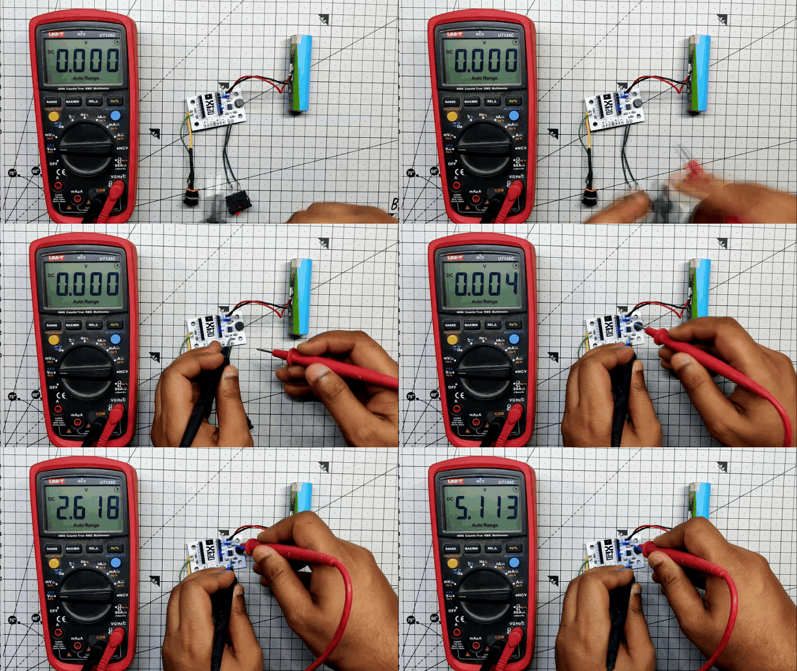
Once the rocker switch and DC jack have been soldered, we can attach a Li-ion battery to the Power board's CON2 Port and turn on the rocker switch to turn on the Power board and illuminate the status LED.
The voltage between the output ports of the IP5306 IC will be 5 volts at this point, indicating that the circuit is operational.
Also, a conventional USB cable is cut and a male 5mm barrel jack connection is attached with the positive and negative wires of the USB cable to charge the Li-ion battery. This arrangement is then charged using a standard smartphone charger using the Makeshift USB-Barrel Jack Cable.
Wiring

.gif)
.gif)
The wiring for this arrangement couldn't be simpler; first, we link the parallel-connected LED boards to the power board's VCC, then we connect the D0 pin to the first LED board's IN port, the second LED board's OUT to the second LED board's IN port, the third board's IN port, and so on.
Together with the battery, the rocker switch, and the DC jack, the potentiometer is also connected to the power board.
By following the given wiring diagram, we connected all these components together and uploaded the main code to the XIAO M0 Board.
Main CODE
Here's the main code that was used in this build:
#include <Adafruit_NeoPixel.h>

#define PIN            1  // Digital pin connected to the NeoPixels
#define NUMPIXELS      32 // Number of NeoPixels

Adafruit_NeoPixel strip = Adafruit_NeoPixel(NUMPIXELS, PIN, NEO_GRB + NEO_KHZ800);

int potPin = 0;   // Analog pin connected to the potentiometer
int potValue = 0;  // Variable to store potentiometer value

void setup() {
  strip.begin();
  strip.show(); // Initialize all pixels to 'off'
  randomSeed(analogRead(0)); // Seed the random number generator
}

void loop() {
  potValue = analogRead(potPin); // Read the potentiometer value

  // Map the potentiometer value to the range of NeoPixel colors (0 - 255)
  int hue = map(potValue, 0, 1023, 0, 255);

  // Change the color of all NeoPixels to the mapped hue
  for (int i = 0; i < strip.numPixels(); i++) {
    strip.setPixelColor(i, strip.Color(hue, 0, 255));
  }

  strip.show(); // Update the NeoPixel strip
  delay(100);   // Add a small delay for smoother operation
}
This code is for controlling 32 NeoPixels using an XIAO M0 and a potentiometer. NeoPixels are programmable RGB LEDs that can display a wide range of colors. The code uses the Adafruit NeoPixel library to control the NeoPixels. Let's break down the code step by step:
Include the Adafruit NeoPixel library:
#include <Adafruit_NeoPixel.h>
This line includes the Adafruit NeoPixel library, which provides functions and methods for controlling NeoPixels.
Define some constants:
#define PIN            1   // Digital pin connected to the NeoPixels
#define NUMPIXELS      32  // Number of NeoPixels
Here, you define two constants. PIN specifies the digital pin to which the NeoPixels are connected (pin 1 in this case), and NUMPIXELS specifies the total number of NeoPixels in the strip (32 in this case).
- Create a NeoPixel object:
Adafruit_NeoPixel strip = Adafruit_NeoPixel(NUMPIXELS, PIN, NEO_GRB + NEO_KHZ800);
This line initializes an instance of the Adafruit_NeoPixel class named strip with the number of pixels and pin information. NEO_GRB specifies the color order (Green, Red, Blue) for the NeoPixels, and NEO_KHZ800 sets the data transmission frequency to 800 KHz.
Define variables for the potentiometer:
int potPin = 0;    // Analog pin connected to the potentiometer
int potValue = 0;  // Variable to store potentiometer value
These variables are used to read the analog value from a potentiometer connected to analog pin 0 and store the potentiometer's current value.
Setup function:
void setup() {
  strip.begin();                // Initialize the NeoPixel strip
  strip.show();                 // Initialize all pixels to 'off'
  randomSeed(analogRead(0));    // Seed the random number generator
}
In the setup function, you initialize the NeoPixel strip, turn off all pixels initially, and seed the random number generator with an analog reading from pin 0. Seeding the random number generator is useful if you plan to generate random colors or patterns later in the code.
Loop function:
void loop() {
  potValue = analogRead(potPin); // Read the potentiometer value

  // Map the potentiometer value to the range of NeoPixel colors (0 - 255)
  int hue = map(potValue, 0, 1023, 0, 255);

  // Change the color of all NeoPixels to the mapped hue
  for (int i = 0; i < strip.numPixels(); i++) {
    strip.setPixelColor(i, strip.Color(hue, 0, 255));
  }

  strip.show(); // Update the NeoPixel strip
  delay(100);   // Add a small delay for smoother operation
}
In the loop function, the code continuously reads the analog value from the potentiometer, maps that value to a hue value between 0 and 255 (to control the color), sets all NeoPixels to that color, updates the NeoPixel strip, and adds a small delay for smoother operation. As you rotate the potentiometer, it changes the hue of the NeoPixel strip, allowing you to control the color.
3D Parts
.gif)
Let's have a look at all the 3D Parts we need to print. Each part's STL file is attached.
This Model consists of a Base, the Cone Diffuser, the RGB PCB Holding part, and a knob for the potentiometer.
The RGB PCB Holding Part is made up of two parts: an upper portion used to support the RGB LED PCBs and a bottom stand component used to connect the upper LED Holding part to the base.
With a 0.6mm nozzle, 20% infill, and a 0.2mm layer height, all pieces were exported before being 3D printed using white PLA for all parts and yellow PLA only for the base.
RGB PCB Holder Assembly
.gif)
.gif)
.gif)
- Super glue was used to adhere the PCB to each side of the LED Holder after first desoldering the LED PCB from the power board arrangement.
- Using three M2 screws, we next join the lower stand component to the LED Holder.
Base Assembly
.gif)
.gif)
.gif)
- The power board, M2 screws, rocker switch, DC barrel jack, and potentiometer are among the components that must be assembled before the base can be put together.
- The rocker switch, DC barrel jack, and potentiometer are added once the Power board circuit has been installed in its proper location.
- The potentiometer's 3D-printed knob is then attached.
Putting Things Together
.gif)
.gif)
.gif)
.gif)
.gif)
- To begin the final assembly, we use three M2 screws to join the LED Holder assembly and lower base assembly.
- We then use the same wiring schematic from earlier to connect everything.
- Following wiring, we link the Li-ion Cell's wire harness connector to the battery JST connector and slide the Li-ion Cell into position.
RESULT
.gif)
.gif)
.gif)
.gif)
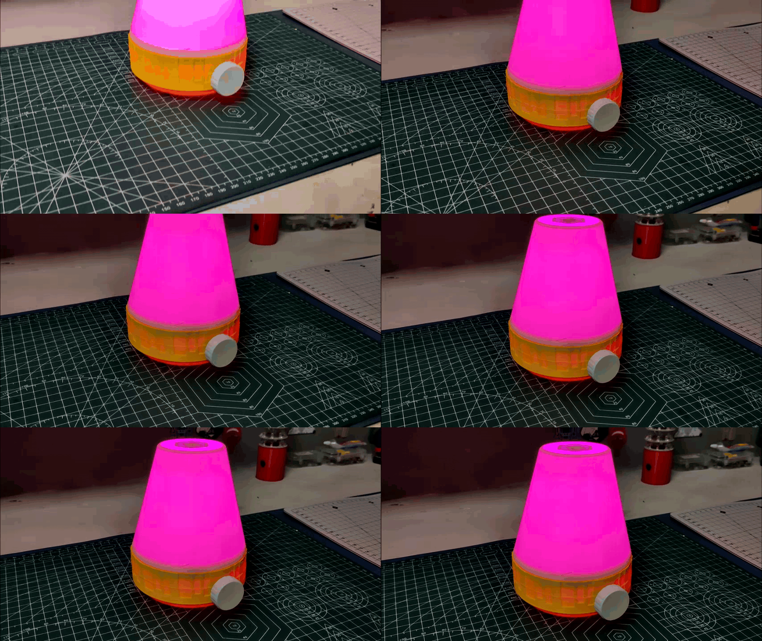
At last, we add the Cone Diffuser in its place, and the CONE LAMP is now ready.
The cone portion serves as a diffuser, absorbing all LED light and dispersing or diffusing it internally to produce a pleasant hue that looks fantastic in low light.
One technique for improving diffusion is to use translucent PLA or print the diffuser portion in transparent resin SLA printers, which will greatly improve the radiance.
By turning the Potentiometer Knob, the hue of blue is controlled, creating different shades of purple.
We may slightly modify the code and upload a code that will randomly change the color of the LEDs as the knob is rotated, or we can specify whatever color we want and use the potentiometer to control that specific color.
Leave a comment if you need any help regarding this project. This is it for today, folks.
Thanks to Seeed Studio for supporting this project, you guys can check them out if you need great PCB and stencil service for less cost and great quality.
And I'll be back with a new project pretty soon!