CNC a Tablet With Pop Art
by PAUL EASTHER Artisan in Workshop > CNC
507 Views, 1 Favorites, 0 Comments
CNC a Tablet With Pop Art
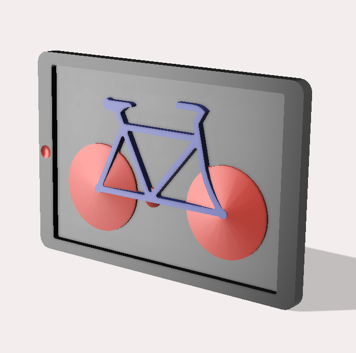
A thought came to me for a decor piece in the shape of a Tablet with a 3D image popping out at you! Colourful with form to catch light and cast shadows! Could be interesting? I thought I'd use a pushbike as the model, but your choice? A quickie CNC wise, as only one sided machining.
Supplies
12mm mdf
Paint to suit
Fusion 360
Use of CNC machine
Design Sketch
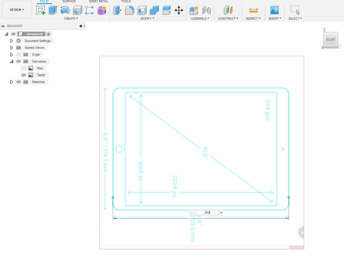
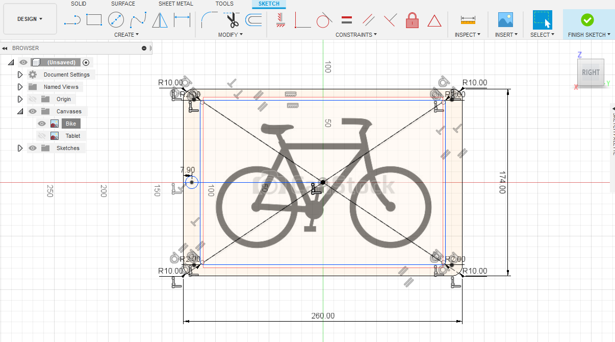
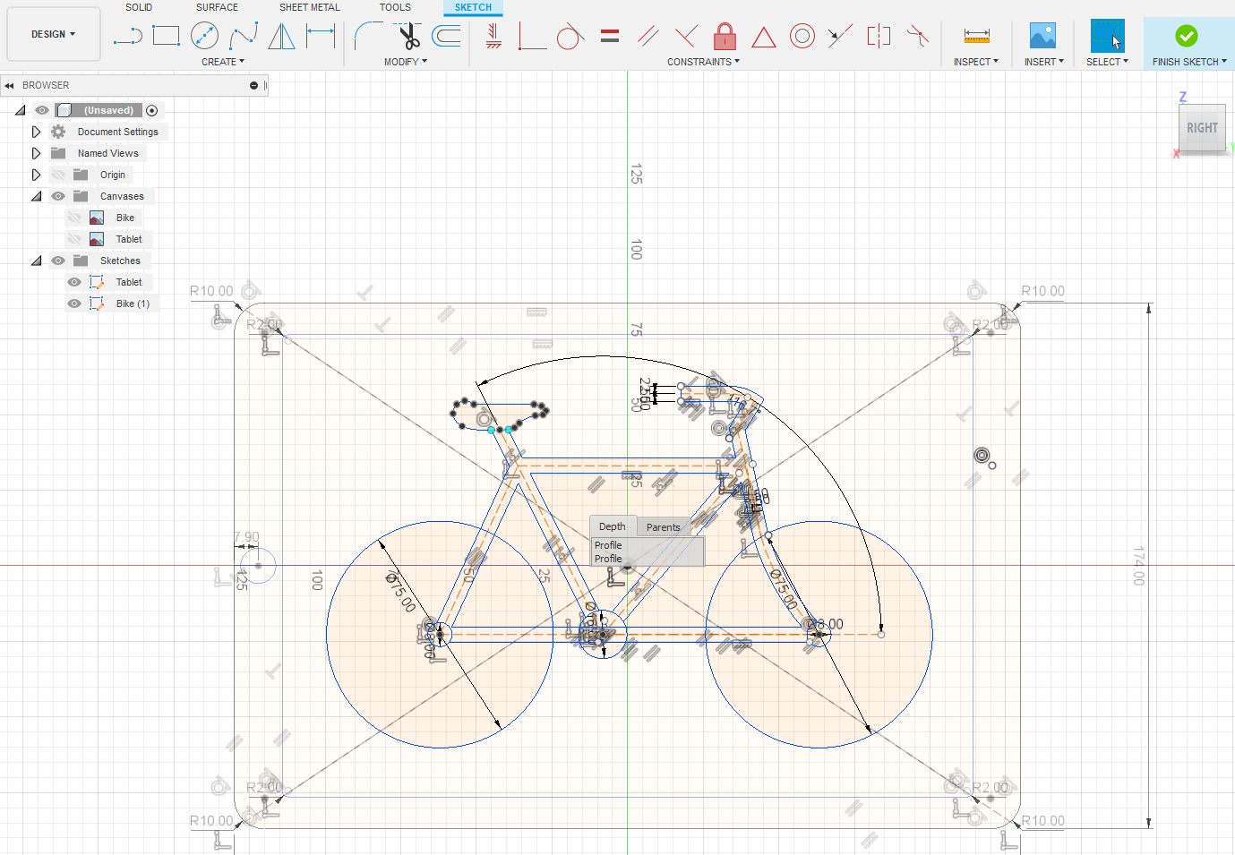
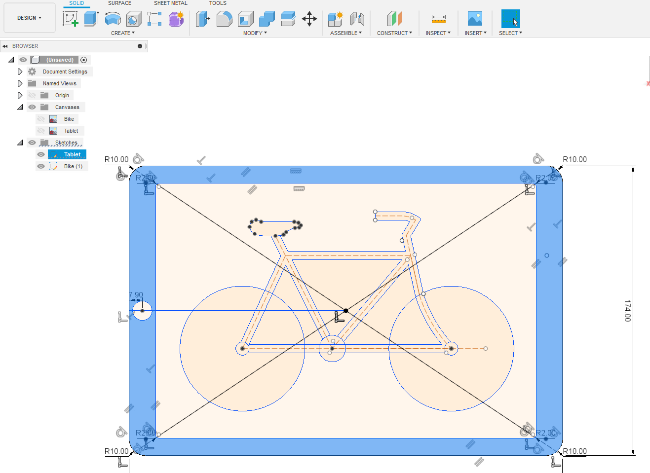
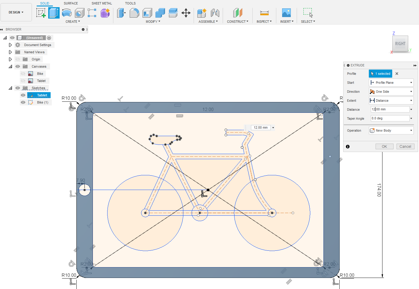
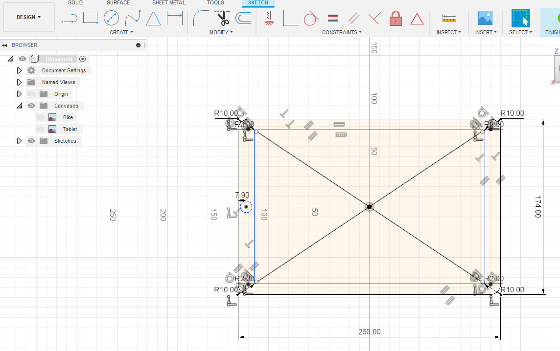
We need something to trace to begin with, a tablet and a bike.
CREATE – Create Sketch -YZ plane. INSERT - Canvas – Image select your bike file (I used
this one: https://www.canstockphoto.com/bike-0782674.html ) Face select YZ plane - OK .
Repeat for tablet image. They're everywhere on the Net.
Select Tablet from tree. Right click ("RC" if you see it again in text) Calibrate. Enter a width after you click two opposite points on canvas. Use sketch tools to copy outline of image. "RC" Bike and Calibrate. FINISH SKETCH.
CREATE – Create Sketch -YZ plane to sketch the bike only. I didn't follow canvas exactly, more as a guide. Label your sketches. FINISH SKETCH
Extruding
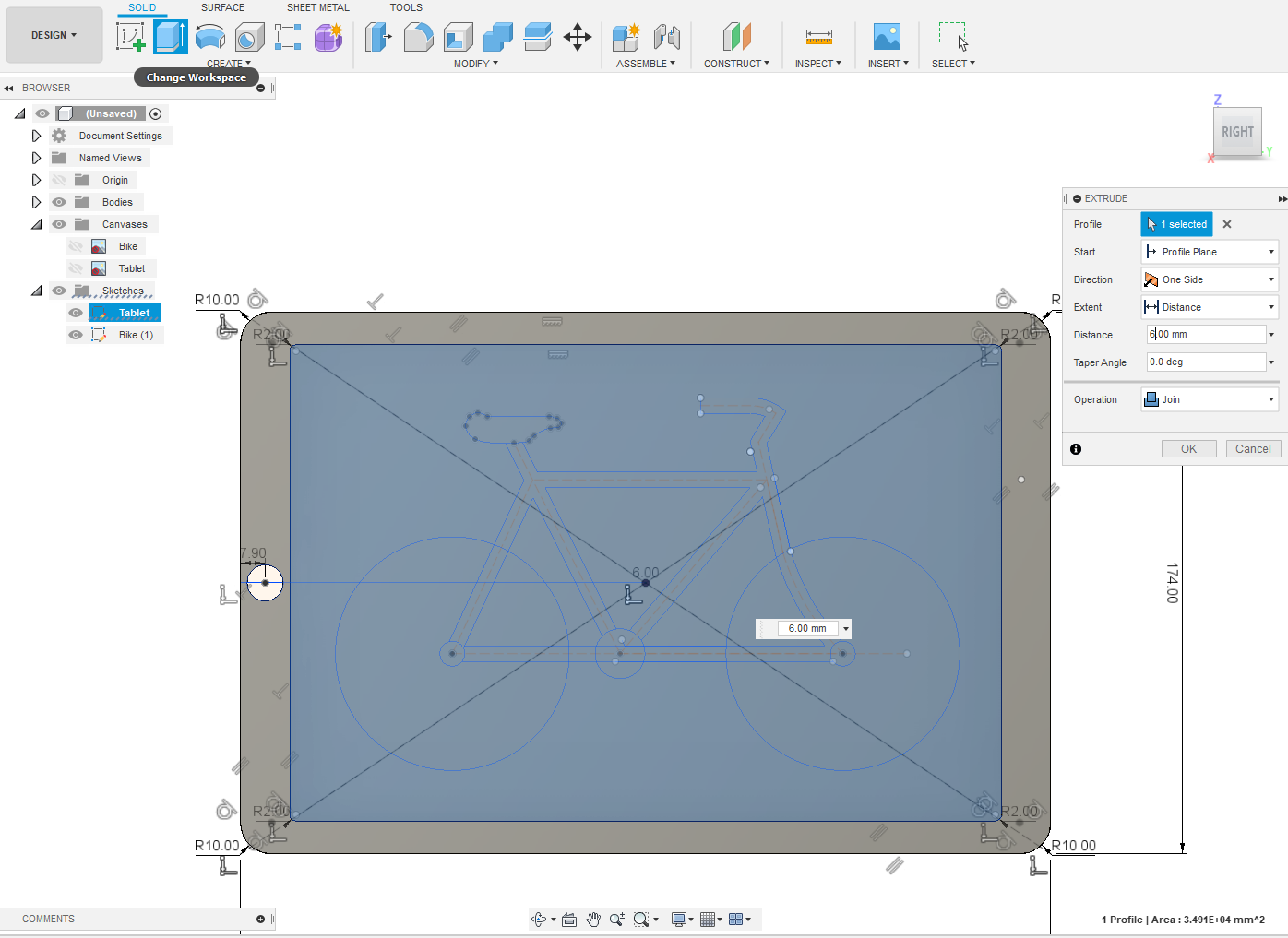
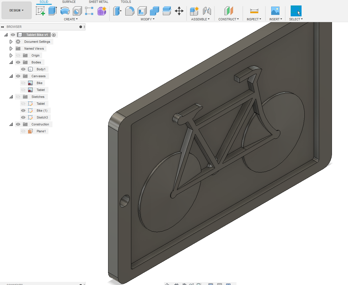
I'm using a piece of 12mm mdf as my material. Select bezel of tablet. "RC" Extrude 12mm – OK Select surrounds
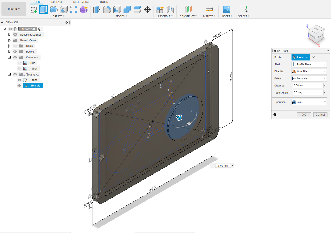
to Bike and Extrude 6 mm – OK. Select the three circles in the Bike sketch and Extrude 8mm – OK. Select Bike
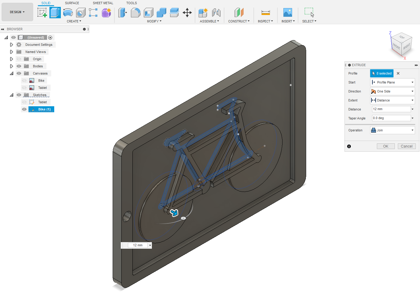
frame, seat and handle bar and Extrude 12mm – OK.
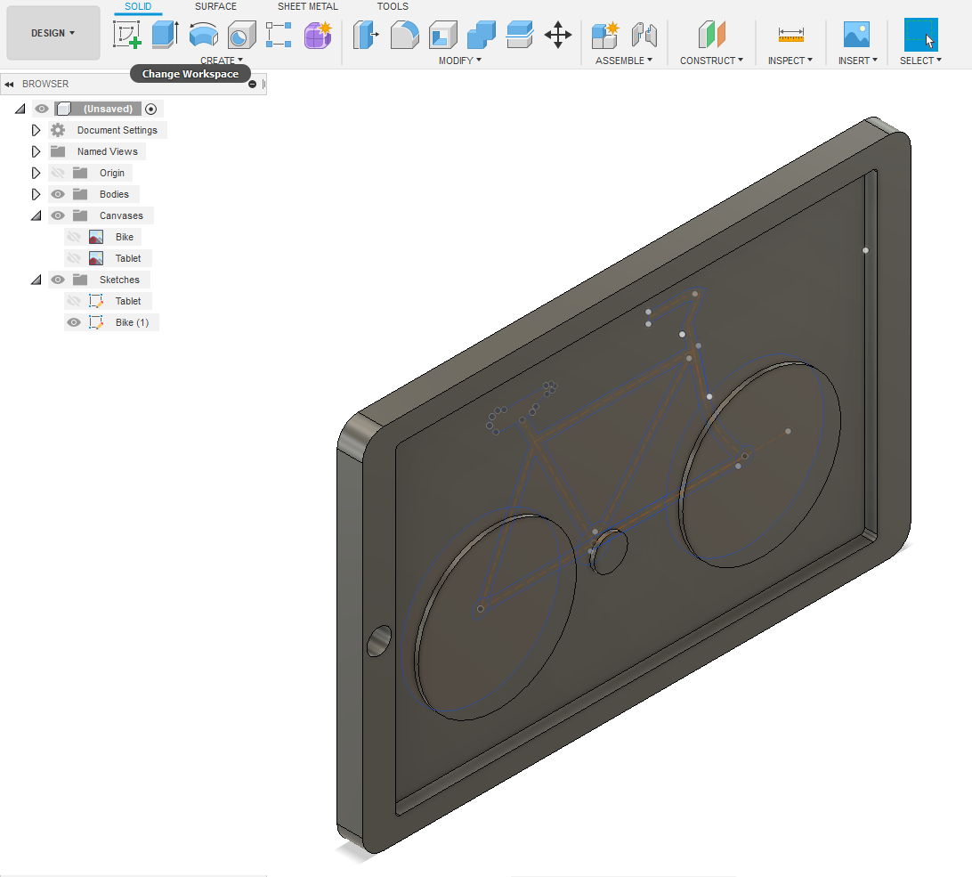
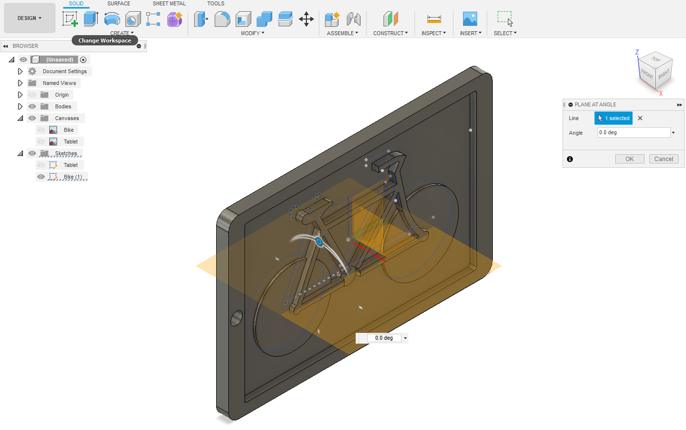
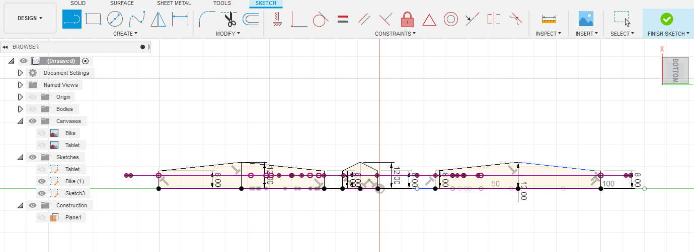
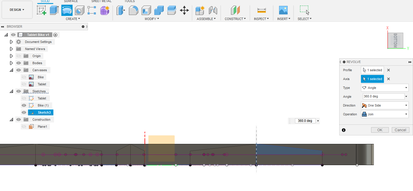
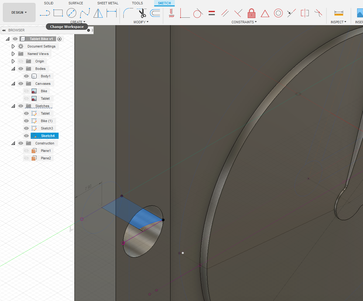
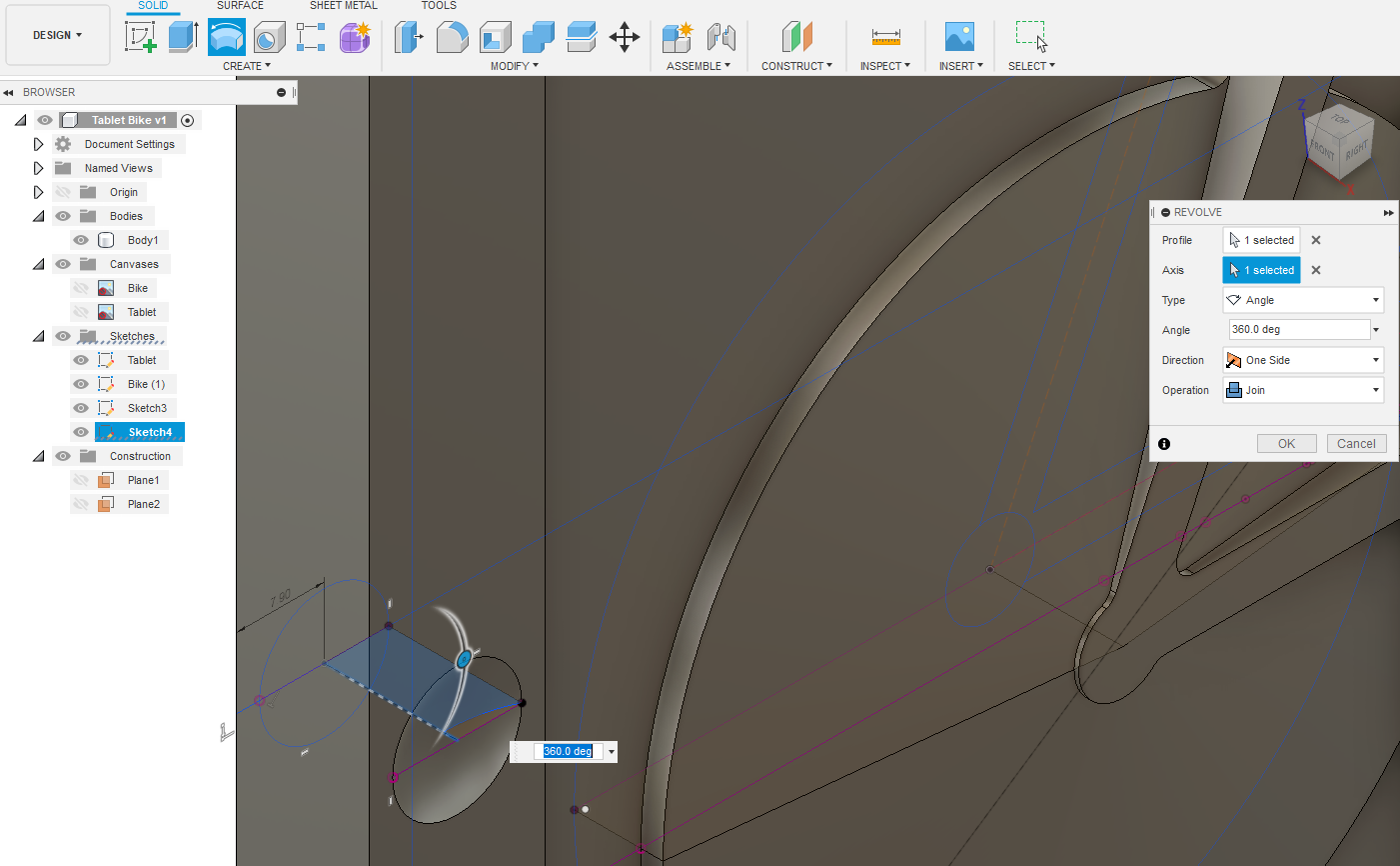
CONSTRUCT – Plane at Angle. Select the horizontal centreline that goes through the three circles – OK. CREATE – Create Sketch on Plane1. CREATE – Project/Include – Project – Geometry symbol. Select perimeter of circles and centre points – OK. Turn view to be looking as if from bottom view? On the baseline draw perpendicular lines up 8mm on circles and 12mm on centre points. Draw lines between top of 12mm and 8mm high lines. FINISH SKETCH. While still on this plane select each half of a circle’s new Profile. CREATE – Revolve. Axis is 12mm high line – OK
Fillets
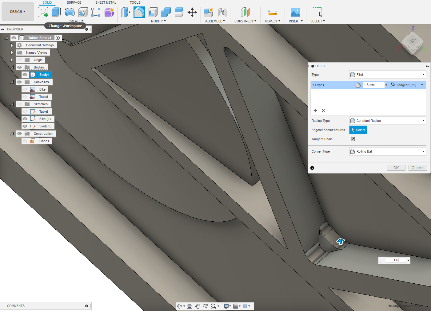
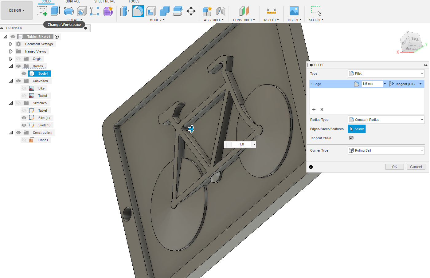
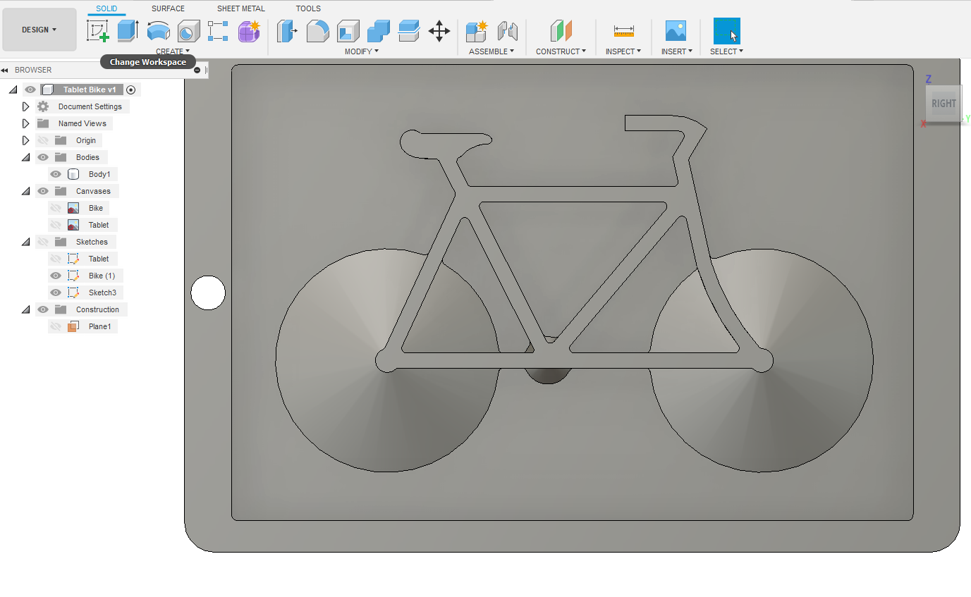
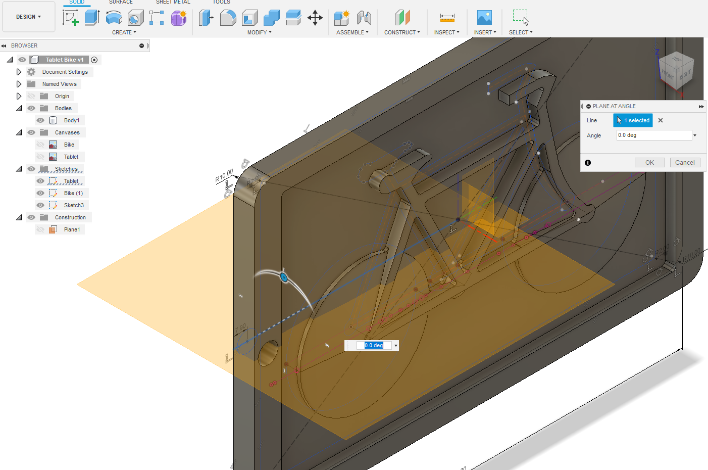
Looking at the Body you should realise that those sharp internal corners are near impossible to replicate given you’re using circular mills? My smallest flat end mill is 3.15mm (1/8") dia. I need to radius all those internal corners 1.6mm radius. MODIFY – Fillet – 1.5mm is the operation. Select all those junctions individually and apply.
It takes the crispness out of the profile’s definition a tad, but that’s the nature of CNC!
Lastly we'll finish the button. CONSTRUCT – Plane at Angle Select the horizontal centreline that goes through the button circle – OK. CREATE – Create Sketch on Plane2. CREATE – Project/Include – Project – Geometry symbol. Select perimeter of circle and draw a half profile of desired shape FINISH SKETCH. Select that half profile and CREATE – Revolve – OK.
That’s it, your done DESIGN wise. Have a bit of fun and RENDER – Appearance paint your body!
MANUFACTURE
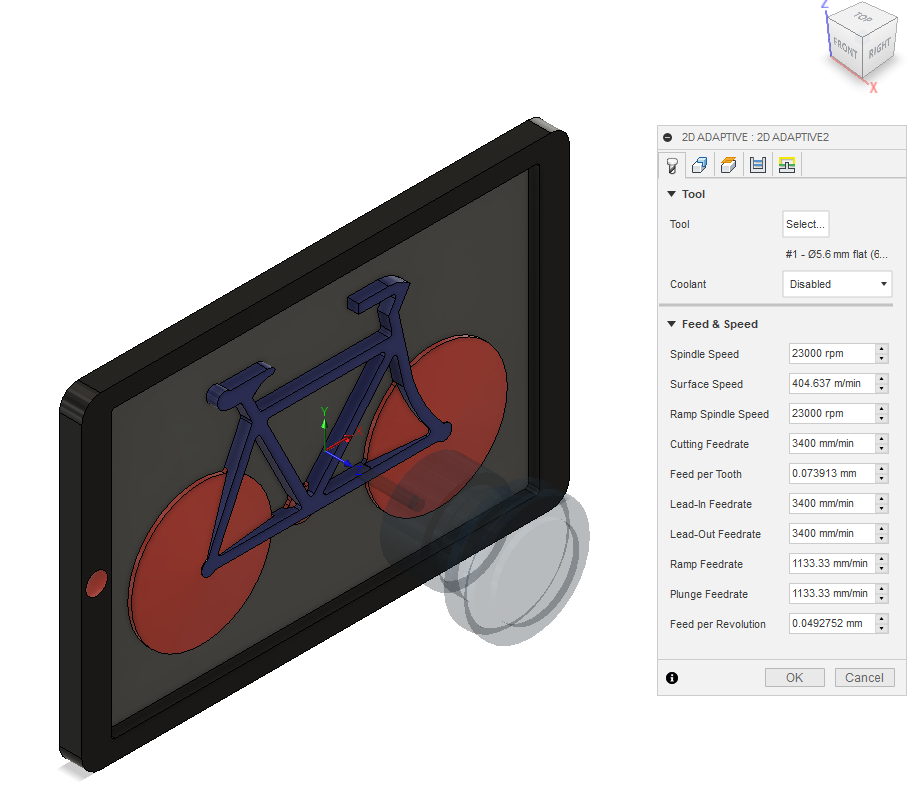
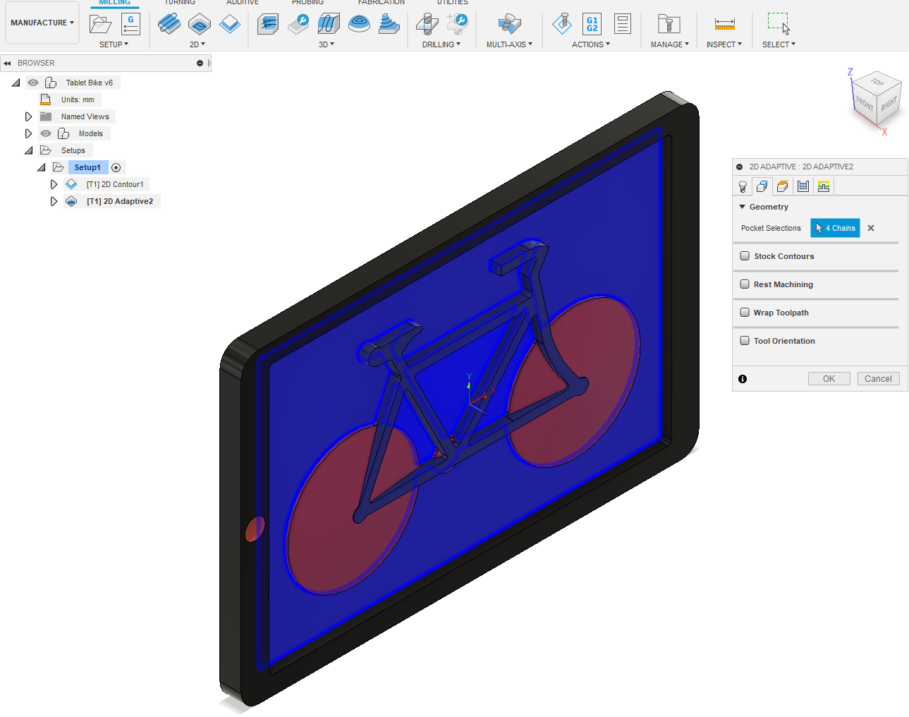
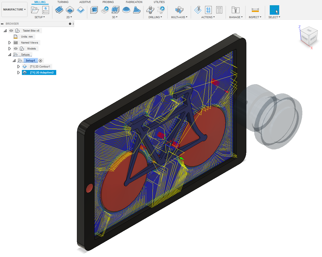
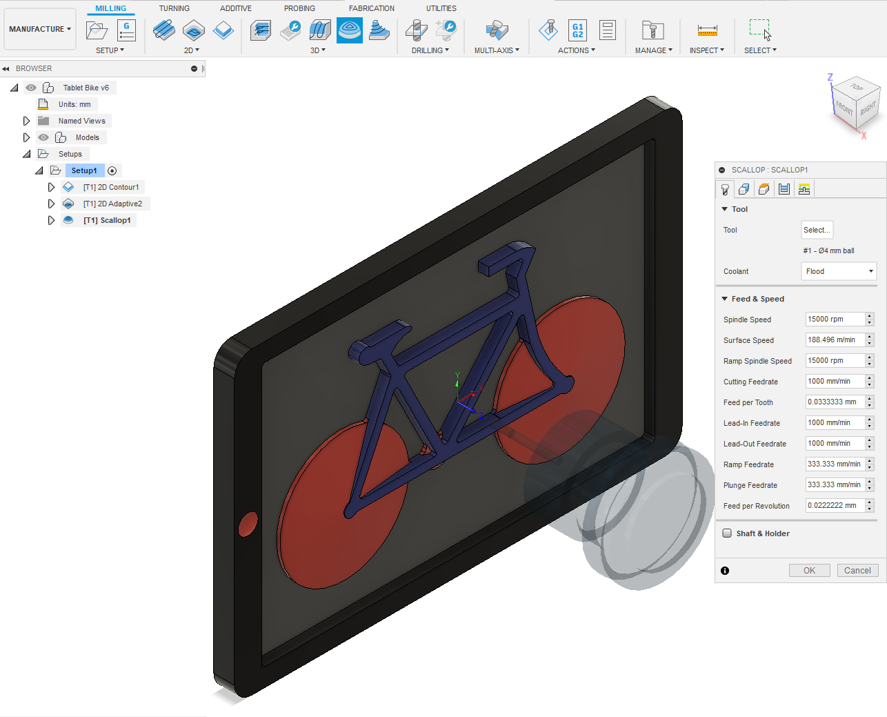
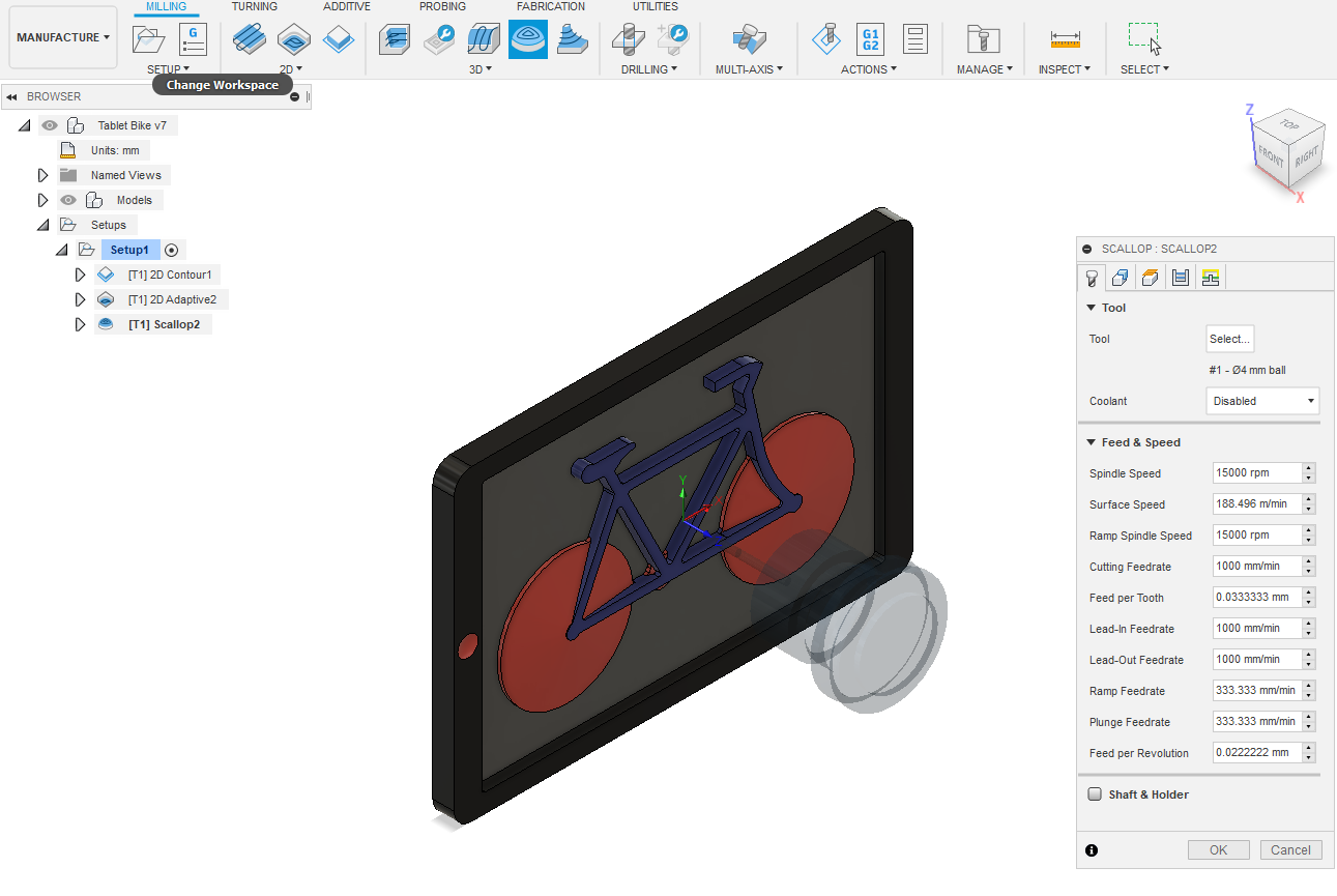
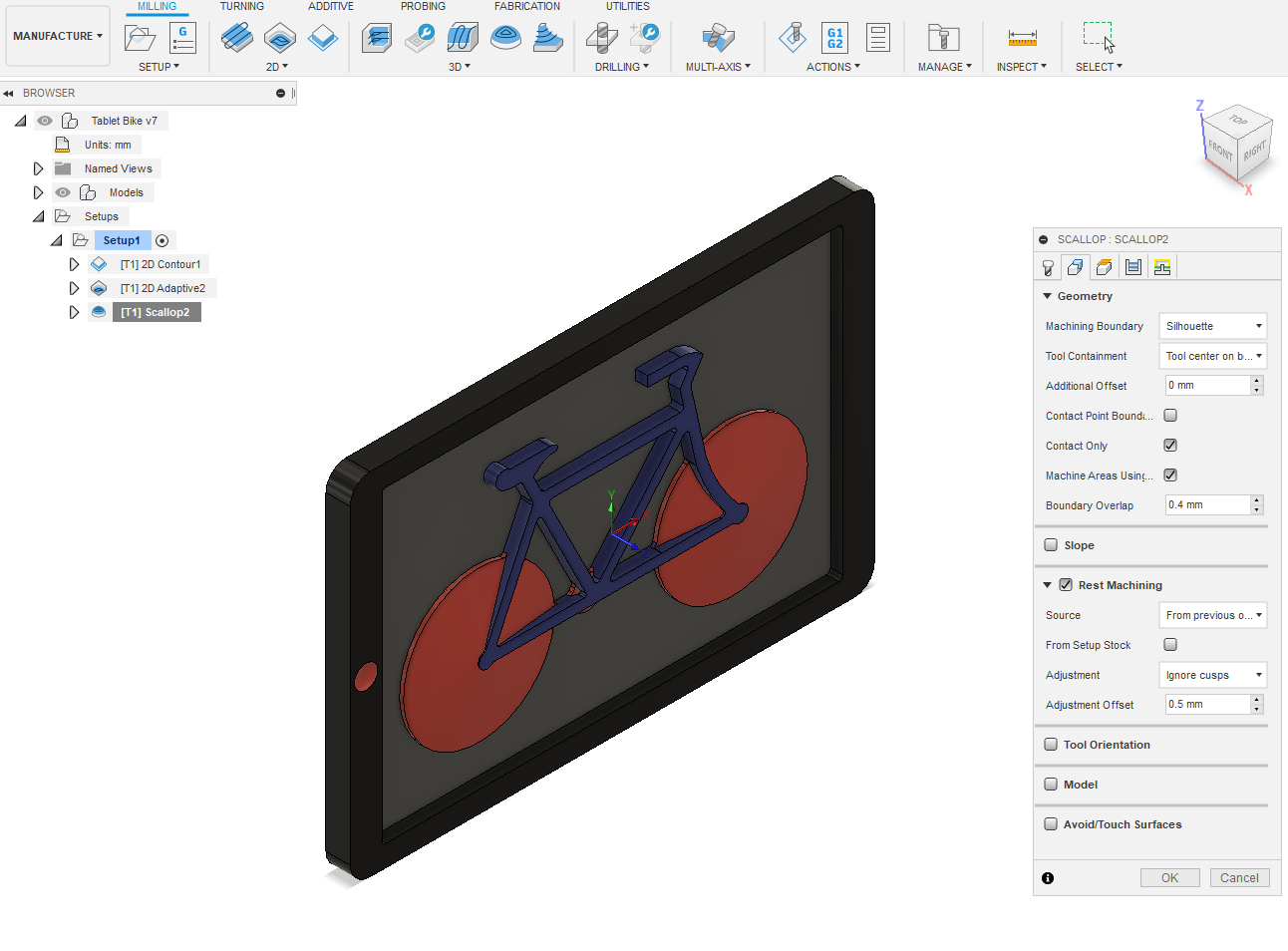
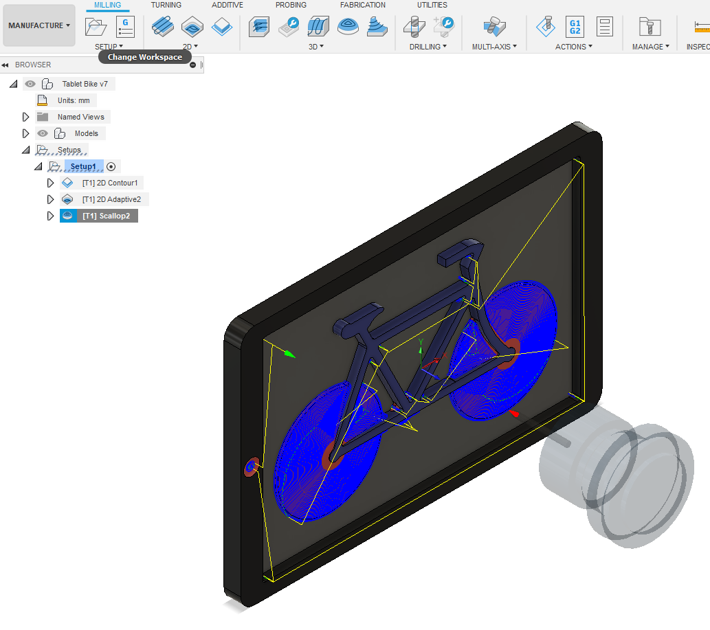
That's what Fusion call it, code for writing machining operations.
MANUFACTURE – SETUP – New Setup. Select Setup tab –
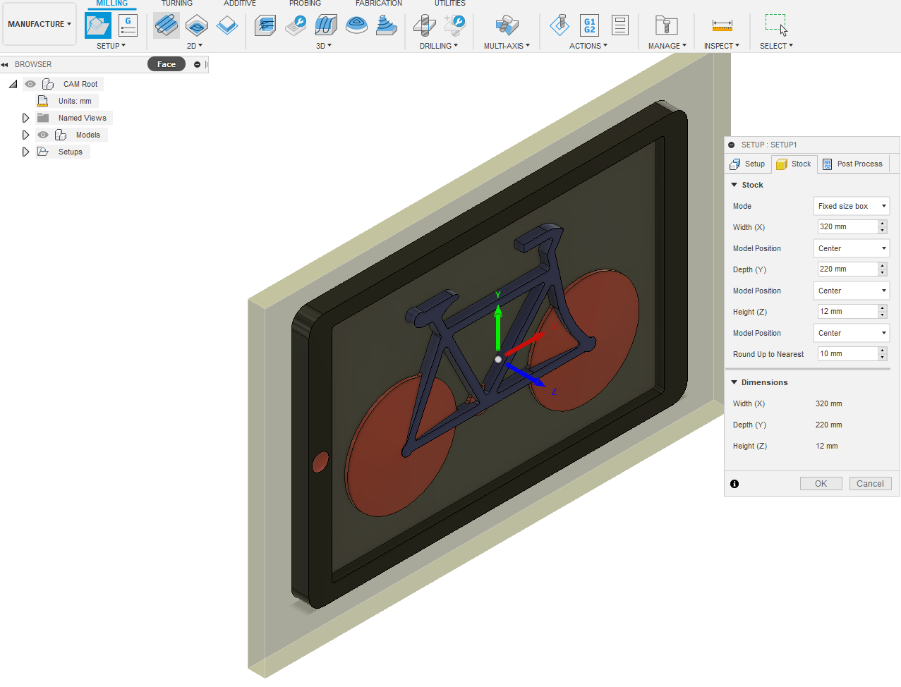
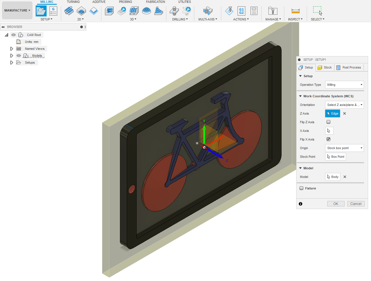
Orientation – Select Z axis. Use mouse pointer to select 12mm long edge. Flip X axis. Select Stock tab – Mode – Fixed size box Width = 320mm, Depth = 220mm and Height = 12mm – OK. This is the size of the mdf you need to sit on your CNC bed. Draw diagonals to find centre point. This will be your XYZ reference for all operations.
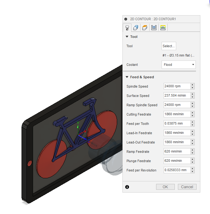
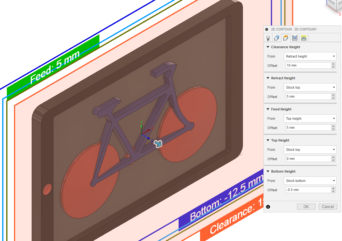
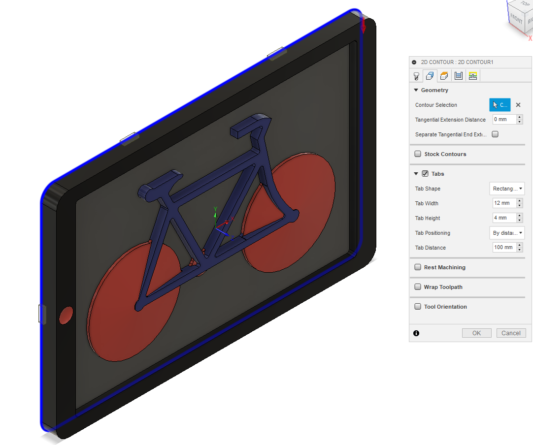
2D – 2D Contour. I select 3.15 mm dia flat end mill. Disable Coolant. Select Geometry tab. With mouse pointer select bottom outside perimeter. Click Tabs Tab Shape – Rectangular; Tab Width – 12mm; Tab Height – 4mm; Tab Distance – 100mm. Select Heights tab. Bottom Height From Stock Bottom – Offset -0.5mm. This ensures that you cleanly cut through the mdf by 0.5mm. Place the 12mm mdf atop a piece of scrap mdf, otherwise you'll be carving up your CNC bed.
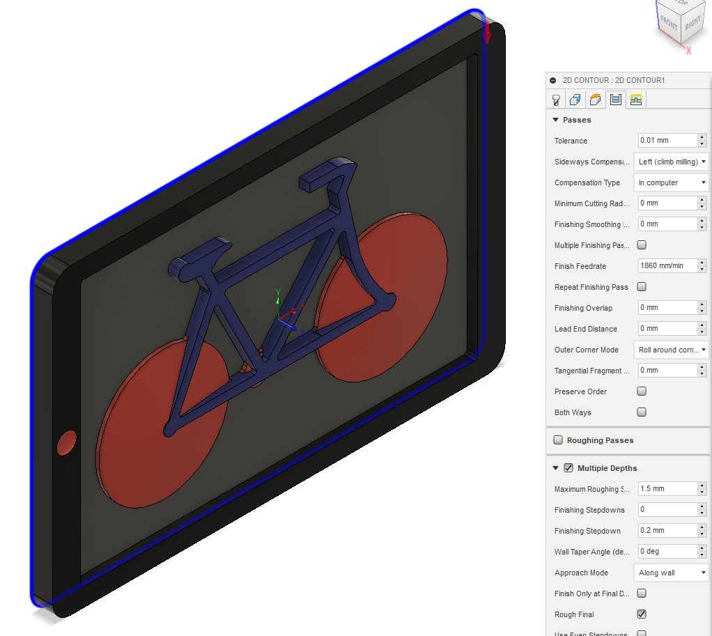
Select Passes tab Tick Multiple Depths Maximum Roughing Stepdown = 1.5mm – OK. Toolpaths will generate. Select ACTIONS – Simulate to watch. If happy, select ACTIONS – Post Process and save to a USB storage device.
Next milling operation. 2D – 2D Adaptive Select 5.6mm dia flat end mill. Select Geometry tab. Un-Tick Rest Machining. Select Geometry tab. Hold down Shift key and select 6mm deep recessed areas. Select Passes tab Tick Multiple Depths – Maximum Roughing Stepdown = 3mm. Untick Stock to Leave – OK
Next milling operation. 3D – Scallop. Select Tool tab. I used 4mm dia Ballnose Select Geometry tab. Tick Rest Machining. Select Passes tab change Stepover to 0.5mm – OK. "RC" Setup1 – Simulate. Watch the entire process.
Now cut through the tabs to release the model. Ready for sanding and paint.