CNC Touch Probe Calibration

by EliBuilds in Workshop > CNC

5690 Views, 38 Favorites, 0 Comments

CNC Touch Probe Calibration

cover.png

There are numerous tutorials available describing how to make your own CNC touch probe. My final probe design combined concepts from several sources into something I thought I could make. I machined what parts I could, but for the most part I did not have the right tools to manufacture the required parts. I do not have access to a lathe or drill press, so there was much dremeling, hacksawing and cordless drill shenanigans. This manufacturing process, in conjunction with less than ideal materials and a $3 collet, culminated in a wildly inaccurate probe.

By the end of this instructable we will transform the probe you see gyrating below into a usable tool.

Supplies

-Wobbly spindle probe

-Something with a circular bore

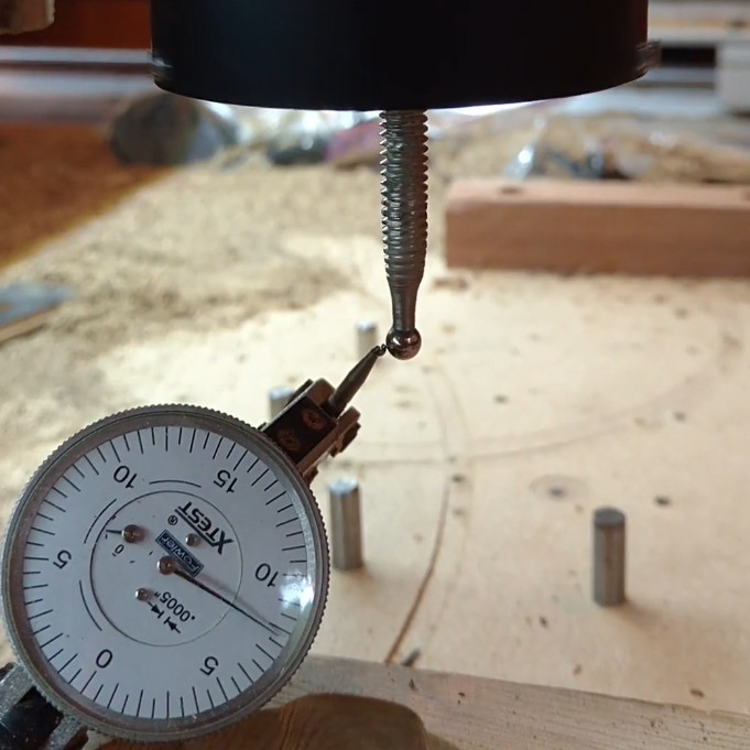
Offsetting the Wobble

To make the probe usable we need a quick way to correct for the wobble every time the probe is used. I used a simple program to measure a predetermined calibration bore at a known fixed position (true center) and then compared it to the probe's output (perceived center). By subtracting the true center from the perceived center you arrive at the calibration vector. You can reuse this calibration vector to compensate for the wobble during any probe cycle as long as the probe does not rotate in the spindle.

Great! So Where Is True Center?

Your calibration bore can be anything circular that you can attach to the bed of your cnc. For this instructable I used a drop that had a circle cut out of it. Then attach that piece to your cnc in a rarely used location so as to not interfere with your other projects. Once you attach it, do not remove it or you will have to start the calibration process from the beginning.

Now it is time to find the true center of the calibration bore. The idea here is to use the uncalibrated probe to get a point cloud representing the bore. Then take the average of the point cloud to get the true bore coordinates.

I measured my point cloud by running basicProbeBore.ngc with the probe inside the calibration bore and rotating the spindle 45° for each data point. The gcode outputs the perceived center coordinates. I recorded all these points and averaged them finding a true center of:
x=52.3959 and y=14.6138

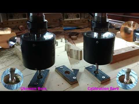
Calibrating & Testing the Probe

After finding the true center, it is now possible to calibrate the probe. When running calibrationOfProbe.ngc the cnc will do the following:

  1. Set g55 x and y to the true center found in previous step (enter them manually into the gcode)
  2. Rapid over g55
  3. Do a z down probe to top of the calibration bore
  4. Set g55 z to current position
  5. Rapid up and over to the true center
  6. Rapid into the calibration bore going -0.125 below the top surface
  7. Perform a simplified version of basicProbeBore.ngc
  8. Subtract g55 [x,y] from probe result [x,y]
  9. Store these values in persistent numbered parameters #198 and #199

Now we can run calibratedProbeBore.ngc on any unknown bore. It will use the calibration parameters #198 and #199 found above to correct the wobble and place the active coordinate system directly on the center of the bore.

The next step shows a video testing both these scripts.

Testing Our Setup

Probe Testing Workflow


Results

UHD Spindle Movie

After the test of concept video I measured the unknown bore at 45° increments. Before each measurement I recalibrated the probe (hopefully removing the wobble error). The results should indicate how much my accuracy had increased.

During each data collection point I took a photo. The video above shows these points in timelapse form (be sure to set the video to loop and HD). There are detail views showing points of interest. The one we are really concerned about is the upper left being completely stationary (indicating the spindle is in the same position above the work piece regardless of probe orientation). There might be a small wobble, but it is nothing like what I had before. The difference is night and day.

Below is a chart where I plotted the effect of the calibration constants.

Conclusion

That's about it. You should be able to apply this calibration technique to other probing cycles by injecting the constants when appropriate. I hope this instructable encourages people to make probes even if they don't have the right tools. You can always fix it later and in addition, it provides a great learning experience.

Ok bye.

Bonus: Probe Design

Here is the model and general plan of the probe. The model doesn't show all the details as I chased a lot of the holes by hand with csink and tap.