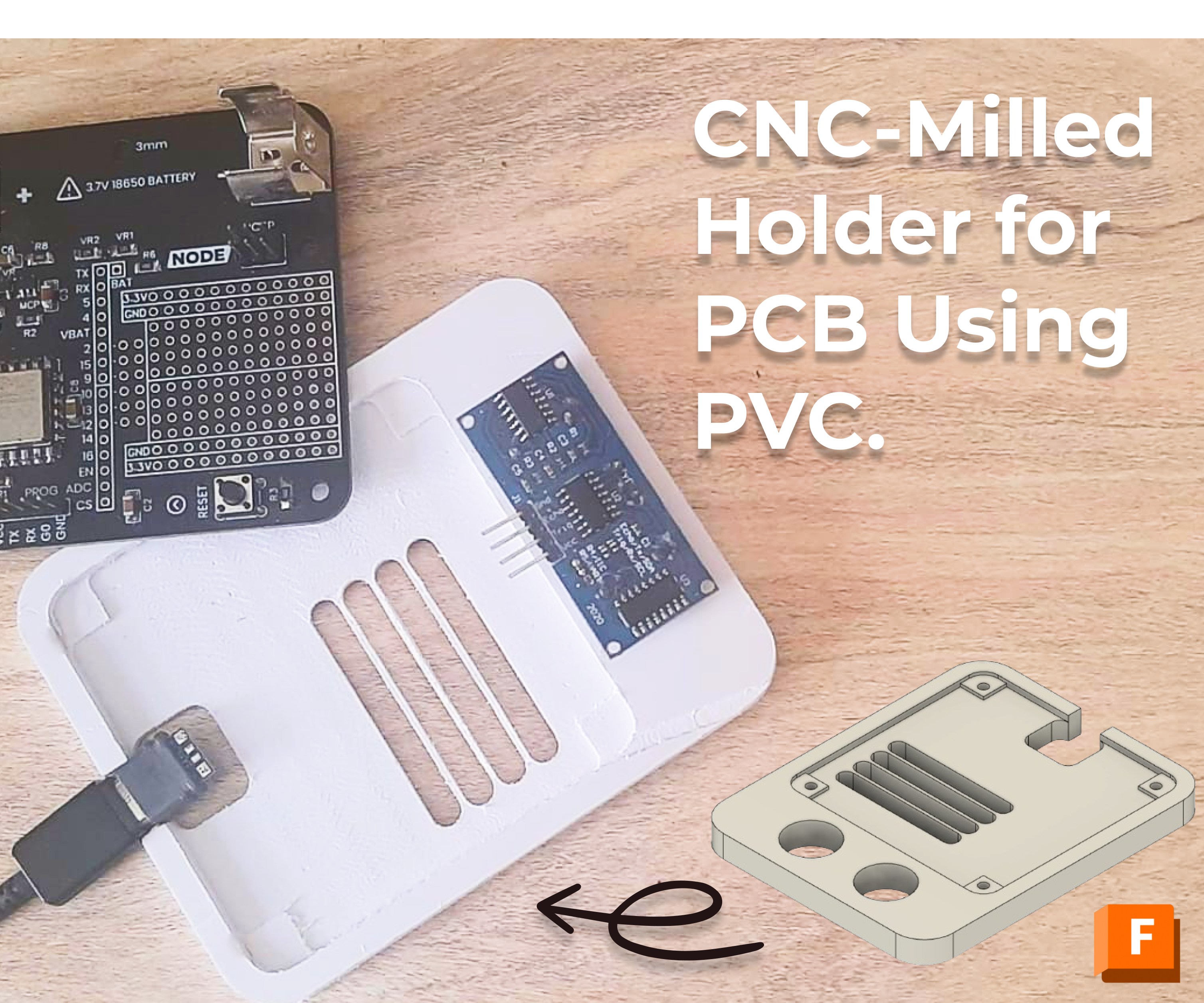
CNC-Milled Holder for PCB Using PVC.
by Rabill_MR in Workshop > CNC
1109 Views, 5 Favorites, 0 Comments
CNC-Milled Holder for PCB Using PVC.
.png)


"Hello tech and CNC enthusiasts! I'm Rabill, a devoted product development student on a journey at the University of Mauritius (UOM). I'm thrilled to unveil my most recent project – a PVC (Polyvinyl Chloride) holder meticulously crafted to enhance the presentation and functionality of my University PCB (Printed Circuit Board) project.
The immersive learning experiences throughout my academic journey have ignited my passion to blend my engineering skills with hands-on craftsmanship, resulting in the inception of this holder. Its primary purpose is to offer a sleek and functional housing for my PCB, while also serving as a conduit to share my design and manufacturing insights with you.
In the design phase, I've leveraged Fusion 360 for Education as a vital tool, ensuring not just precision in crafting the PVC holder but also providing an avenue to showcase the synergy between PCB engineering and CNC technology.
Throughout this guide, I'll meticulously walk you through the step-by-step process of designing and manufacturing the holder, accompanied by valuable resources to empower you in elevating your own PCB projects.
Let the journey commence!
Supplies
You'll need the following supplies:
- Vernier Caliper
- PCB: Have your PCB ready. The holder is specifically designed to house and showcase your PCB, so make sure you have the dimensions and specifications of your PCB on hand.
- Fusion 360: Ensure you have access to Fusion 360, a powerful software for computer-aided design (CAD) and CAM (computer-aided manufacturing). You can use Fusion 360 for Education with your University email to start designing for free.
- CNC Machine: Access to a CNC machine is essential. This machine will bring your design to life by accurately machining the PVC material based on the specifications provided in Fusion 360.
- CNC JS: Familiarize yourself with CNC JS procedures. This involves configuring the CNC machine for your specific job, including toolpaths, cutting depths, and other machining parameters.
With these supplies in place, you're well-equipped to embark on the journey of designing and manufacturing your PVC holder using Fusion 360 and a CNC machine.
Design
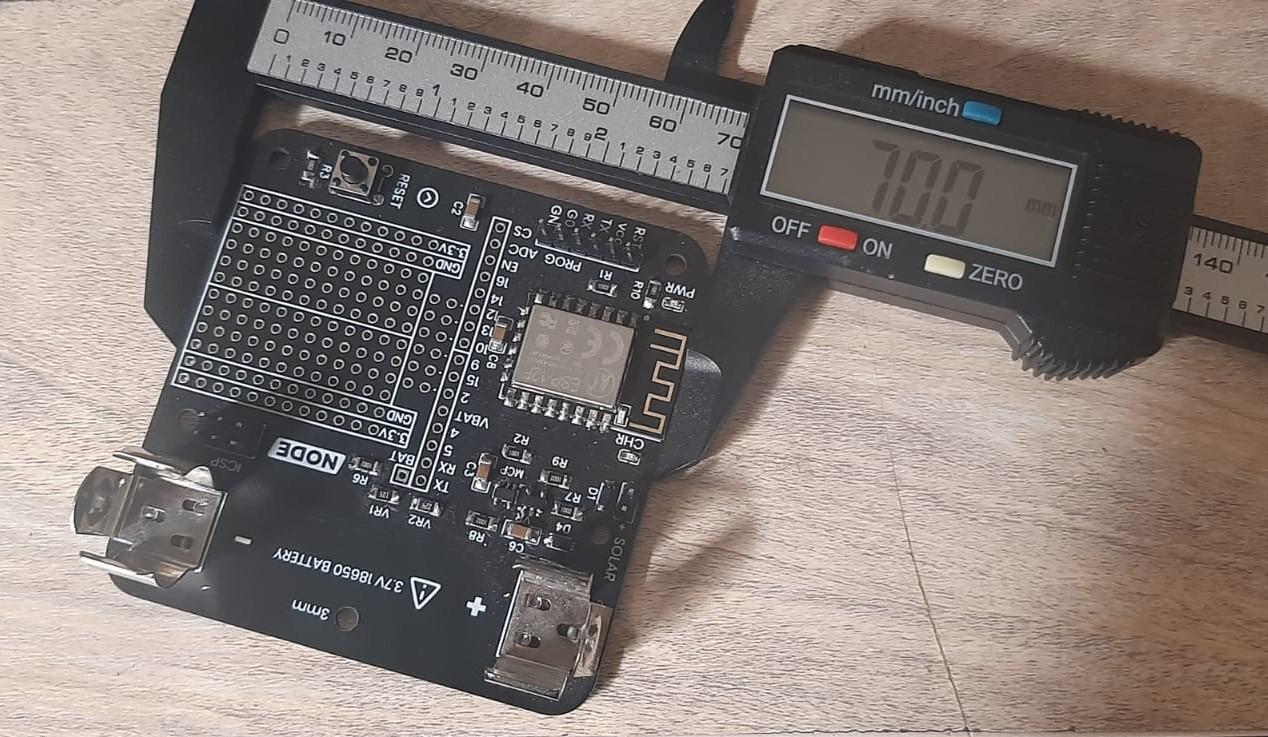
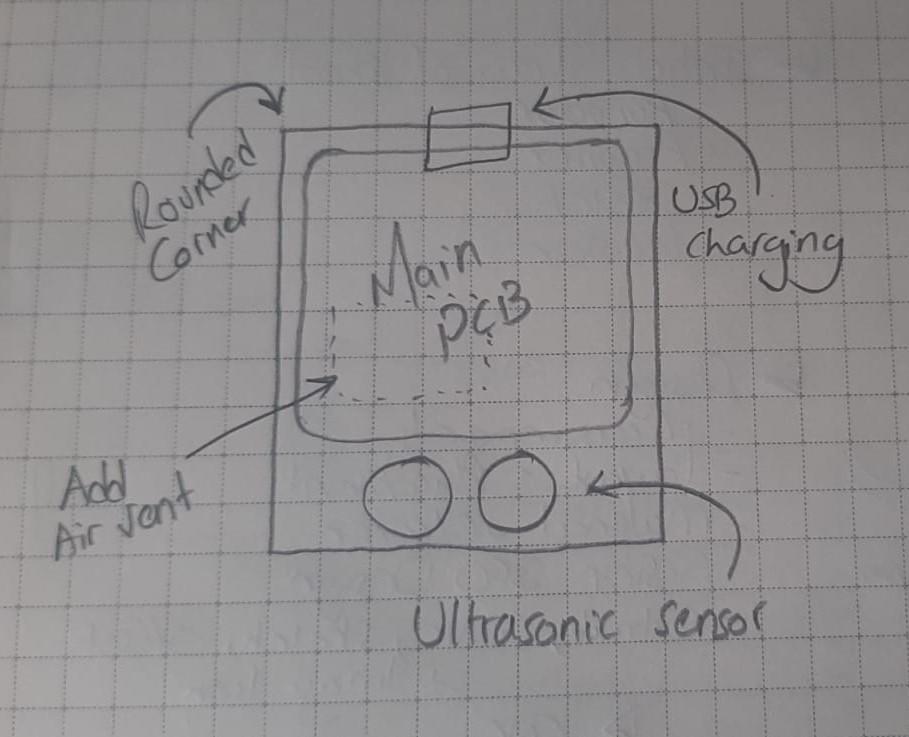
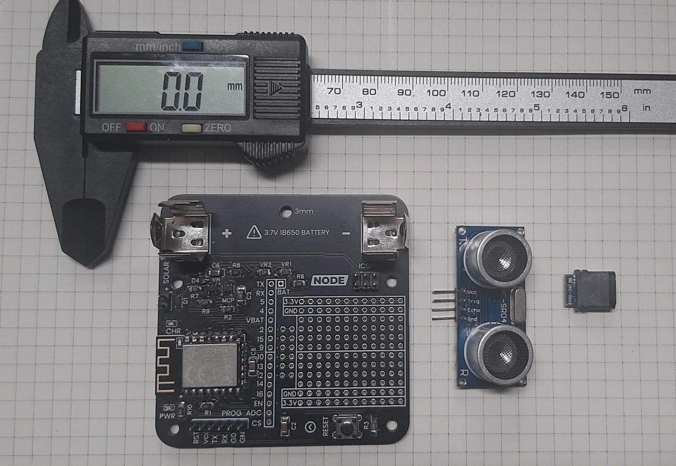
1. Measure the PCB:
Before we start with the design in Fusion 360, accurately measure the dimensions of your PCB using a vernier caliper. Note down the length, width, and any specific features that need to be accommodated within the holder.
2. Determine Layout Placement:
Visualize the layout placement of the PCB within the holder. I personally like to sketch down the layout and features on paper first before start designing. You need to consider factors such as component positions, connectors, and any specific features you want to highlight. This step will guide the initial sketching process in Fusion 360.
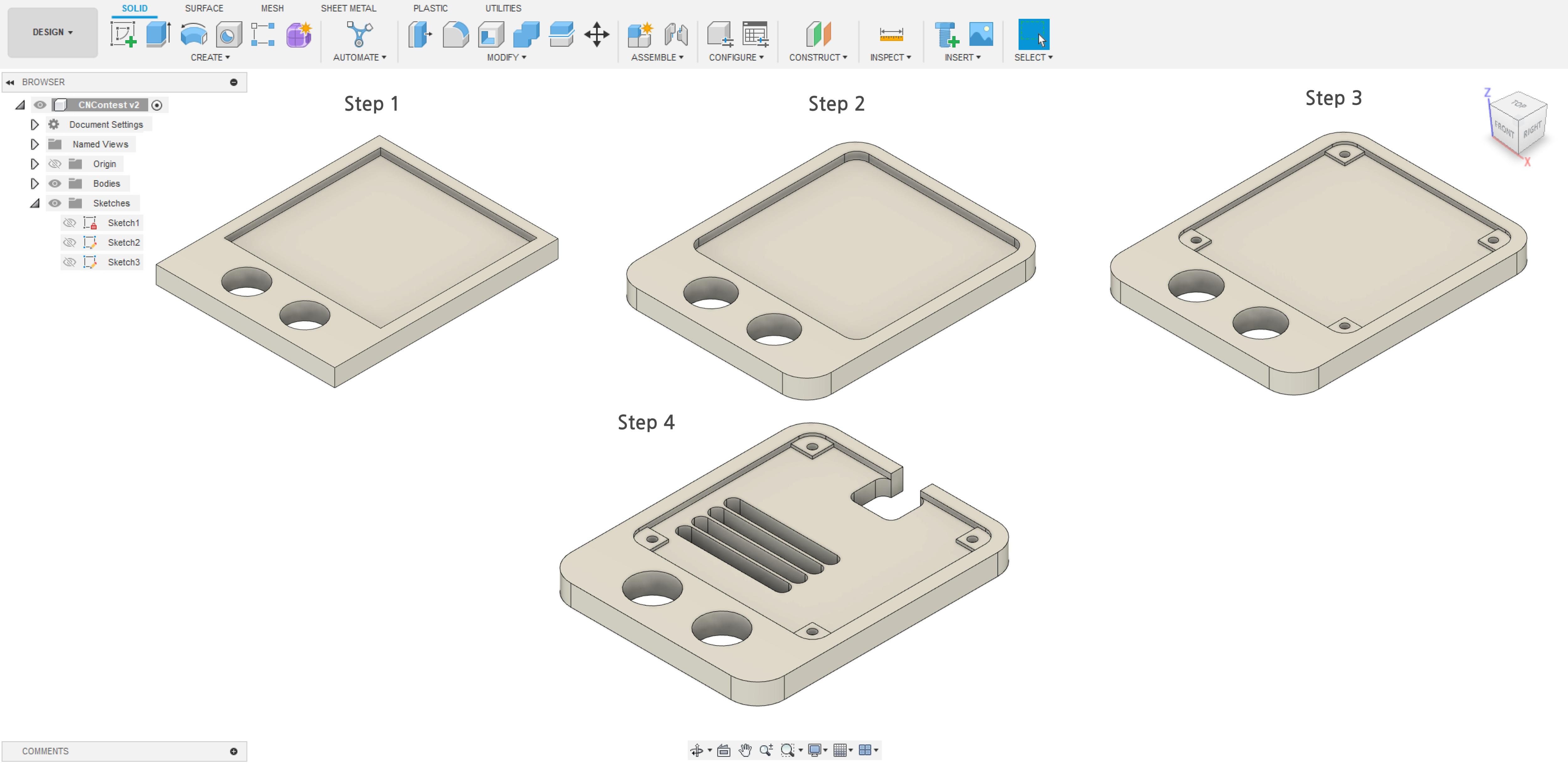
3. Core Aspects in Fusion 360:
In Fusion 360, a multitude of tools offers a wide range of capabilities. However, the primary tools I heavily relied on throughout this project include:
- Extrude:
In Fusion 360, 'Extrude' is a fundamental operation. After creating a 2D sketch representing the base shape of the holder, use the Extrude tool to give it depth and turn it into a 3D model. Input the desired thickness based on the measurements of your PCB.
- Fillet:
'Fillet' is crucial for rounding or chamfering edges, providing a more aesthetically pleasing look and preventing sharp corners. Apply fillets where necessary, especially if you want to enhance the visual appeal and ergonomic aspects of your PVC holder.
- Offset in Sketch:
'Offset' in Fusion 360 allows you to create concentric shapes or duplicate existing lines at a specified distance. Use the 'Offset' tool within your sketch to create features that match the dimensions of your PCB or to add details like slots or ledges for securing the PCB in place.
Manufacturing
.png)
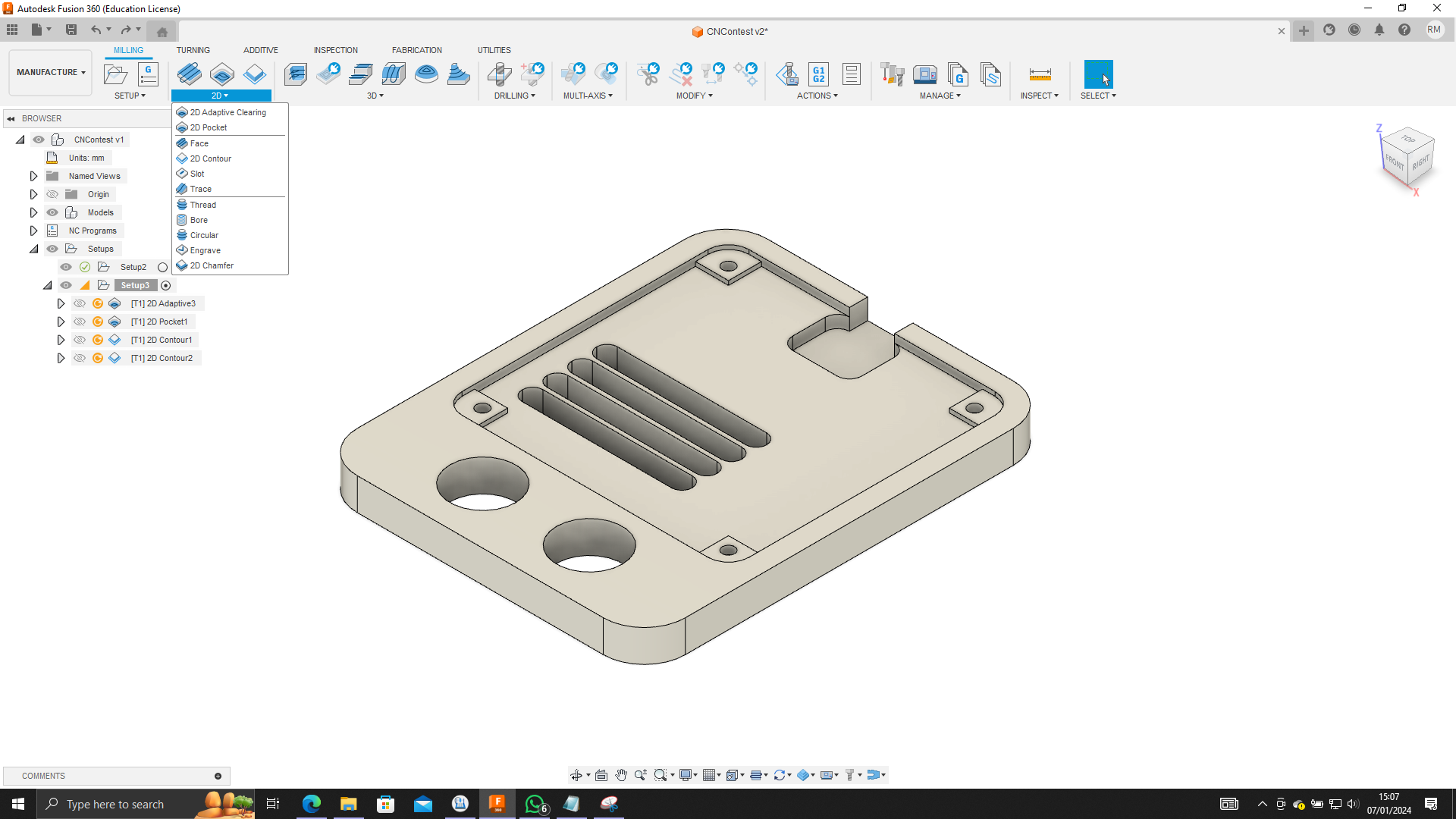
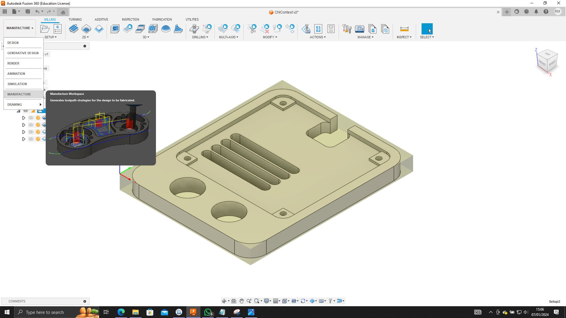
1. Utilizing the Manufacturing Tool:
To seamlessly transition from design to manufacturing in Fusion 360, navigate to the Manufacturing workspace. Here, you'll find a suite of tools designed for CNC machining, ensuring precision and efficiency in the manufacturing process.
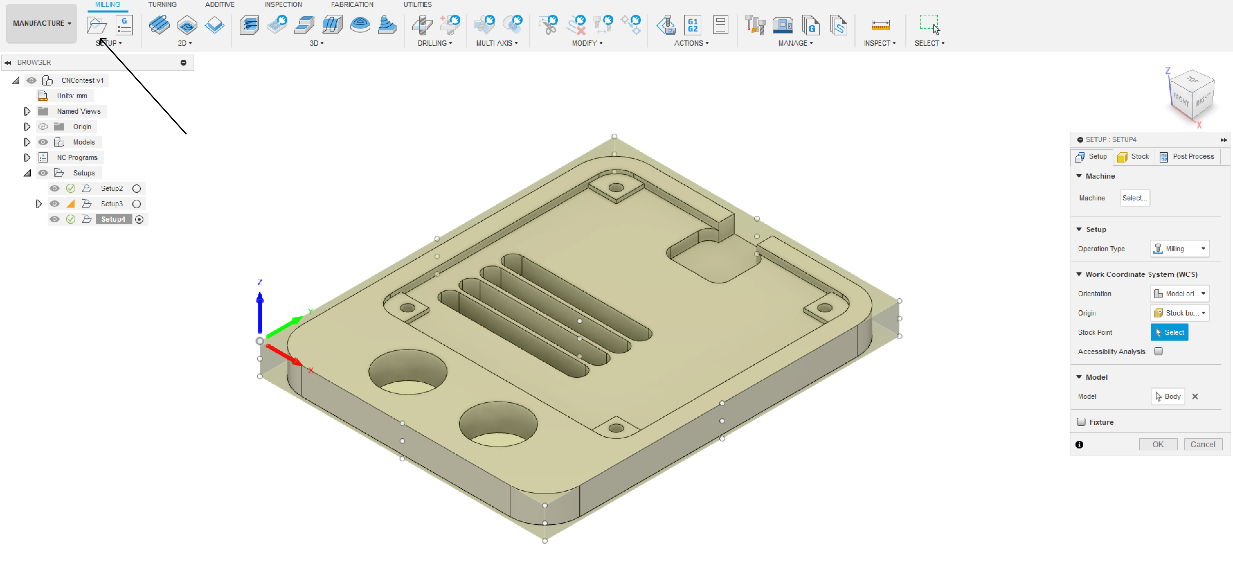
2. Setup of Stock:
Begin by setting up the stock, defining the raw material dimensions within Fusion 360. Specify the material type and dimensions, aligning it with the intended size of your PVC holder. This step ensures accurate machining and optimal material usage and also the starting point of the milling process.
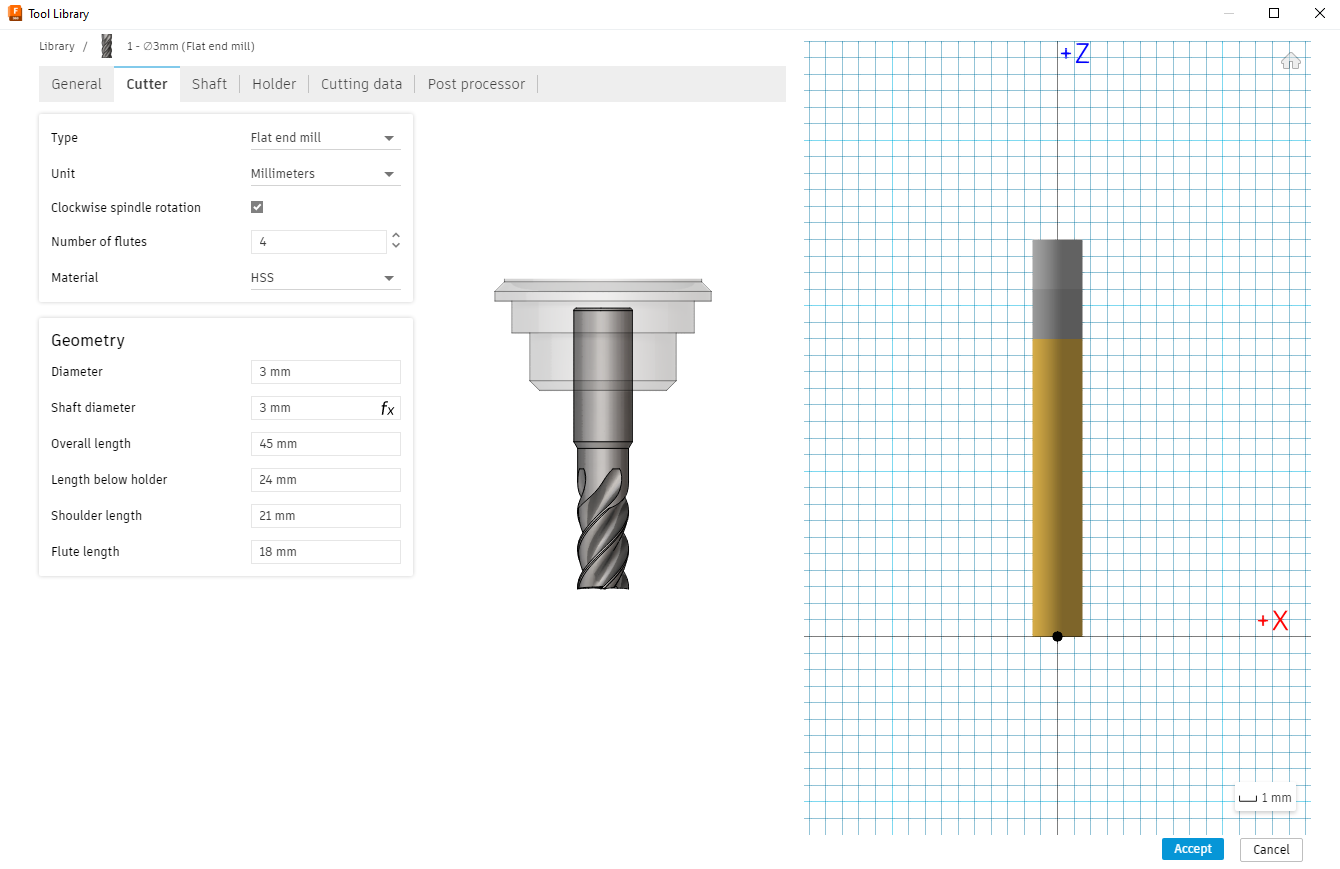
3.Setting up Bit Size and Cutting Parameters:
Before diving into toolpaths, configure your cutting bit size and cutting parameters for the CNC machining process. Define the appropriate tool for each operation, specifying factors like tool diameter, speeds, and feeds. This window can be found in the Tool library.
4. Key Tools in CNC Machining:
- 2D Adaptive Clearing:
This toolpath strategy efficiently removes excess material, adapting to the geometry of your design. Configure parameters such as tool, speeds, and depths to achieve optimal material removal while preserving the integrity of your PVC holder.
- 2D Pocket:
Use the '2D Pocket' tool to clear material within enclosed regions, such as holes or intricate shapes. Configure tool parameters and specify the areas to be machined, ensuring a precise and thorough material removal process.
- 2D Contour:
The '2D Contour' toolpath is instrumental in defining the outer boundaries and intricate details of your design. Specify the contour paths, depths, and cutting parameters to accurately shape the final product.
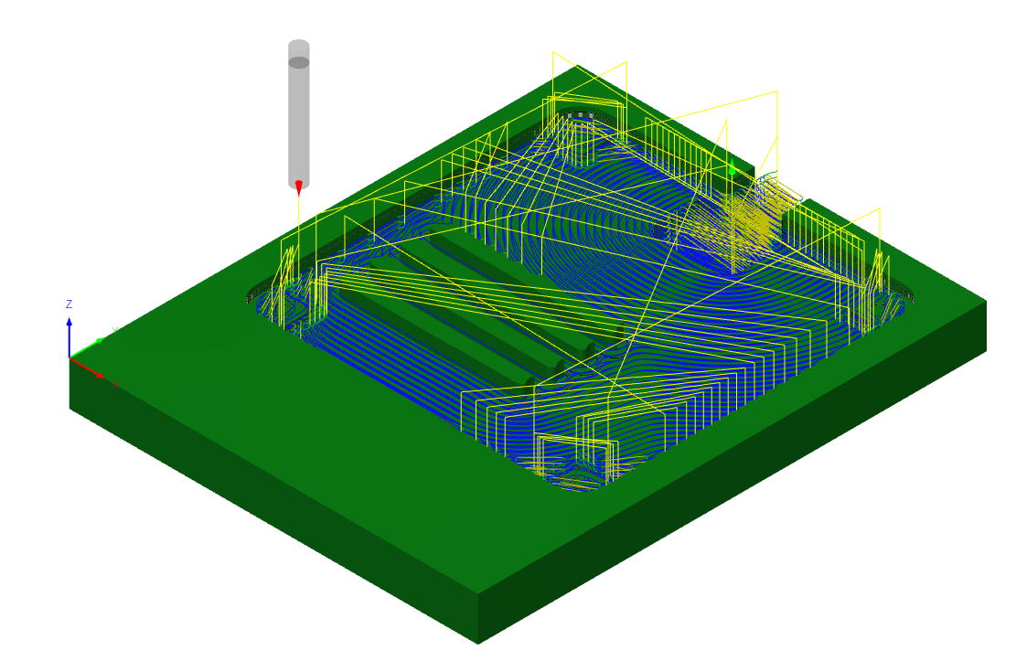
5. Simulation of Manufacturing:
Before initiating the actual machining process, leverage Fusion 360's simulation capabilities. You can simulate the toolpaths to visualize the machining sequence, ensuring that there are no collisions, unexpected tool movements, or issues that might arise during manufacturing. This step helps refine the toolpaths for optimal results.
6. Exporting GCODE:
Once satisfied with the simulation, export the toolpaths as GCODE. Fusion 360 simplifies this process, allowing you to generate GCODE compatible with your specific CNC machine. Save the GCODE file to transfer it to the CNC machine for execution.
CNC Cutting
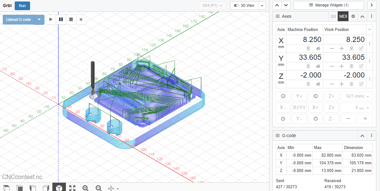
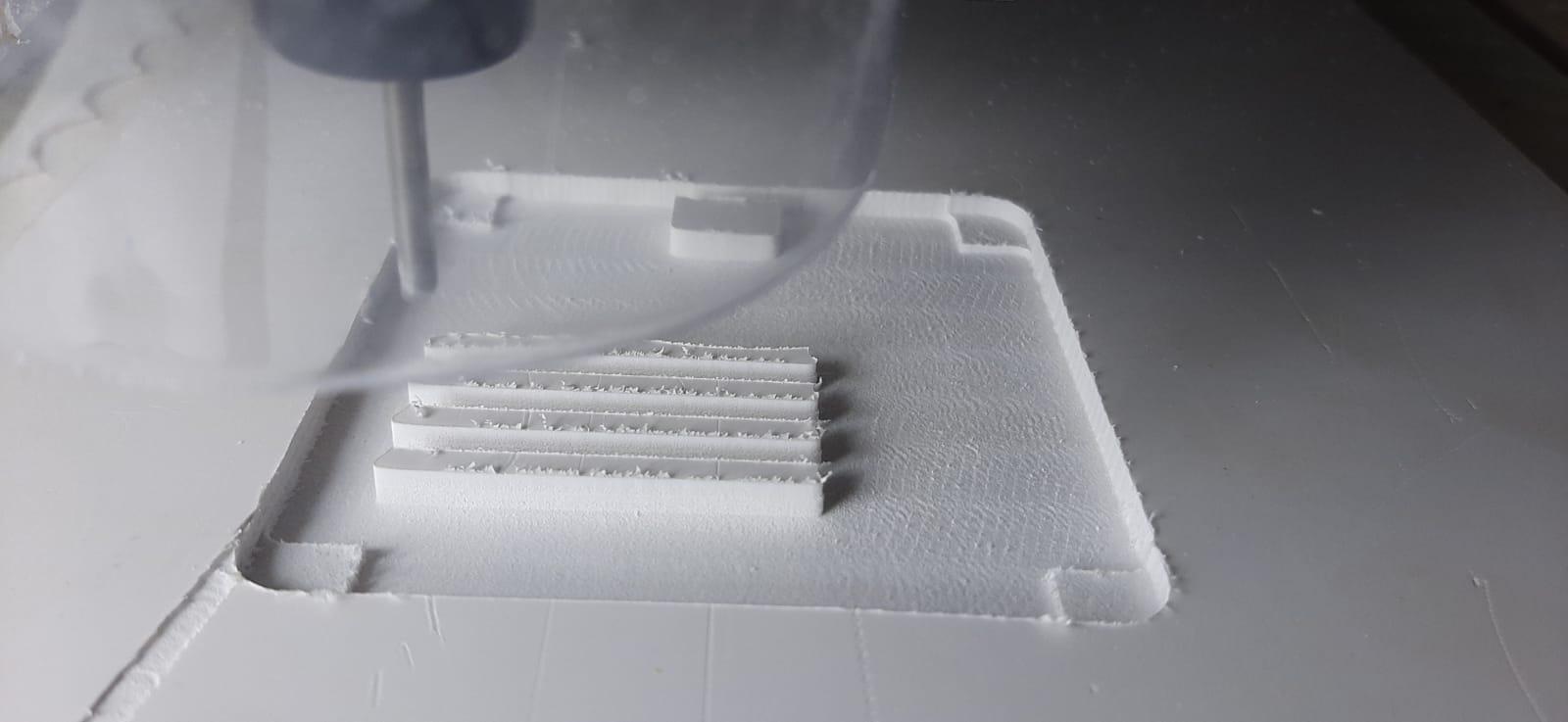
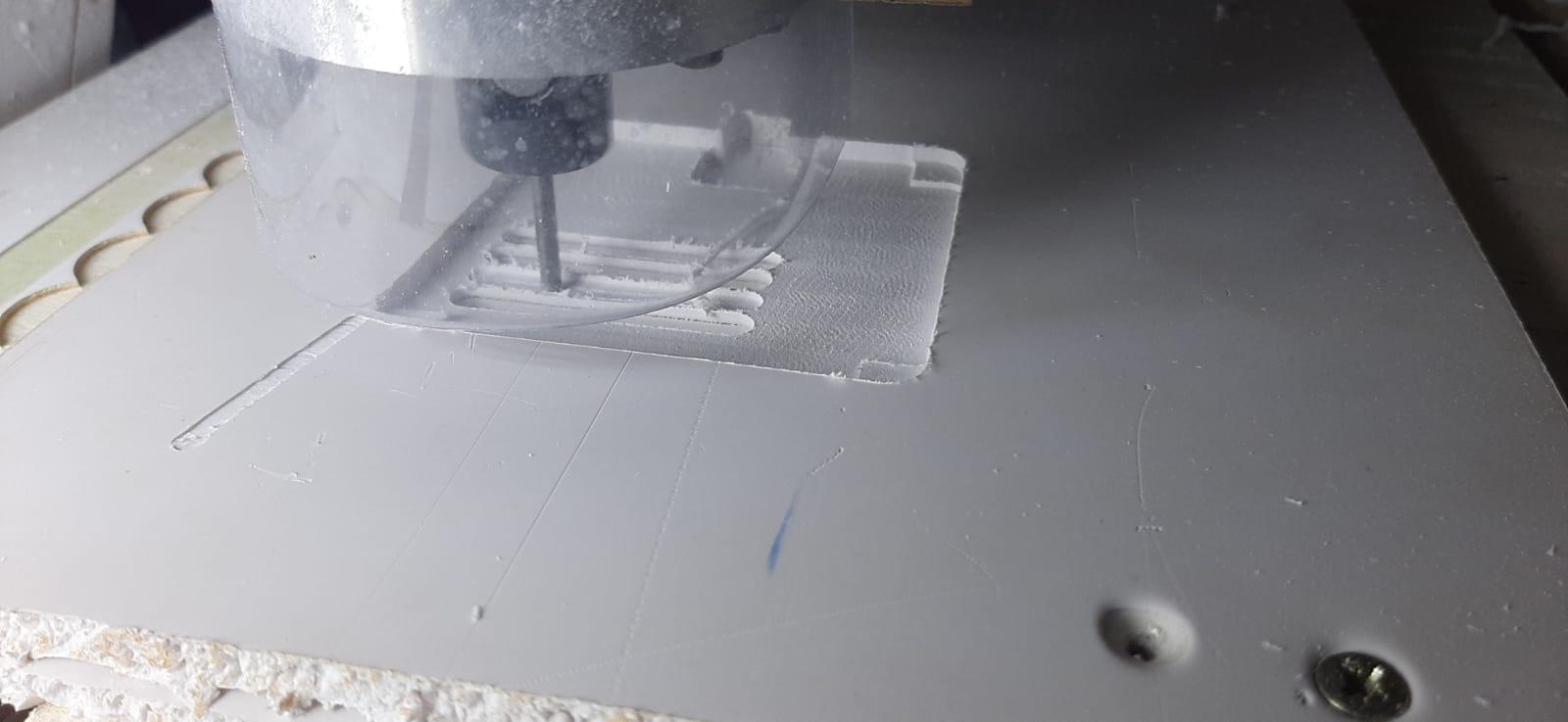
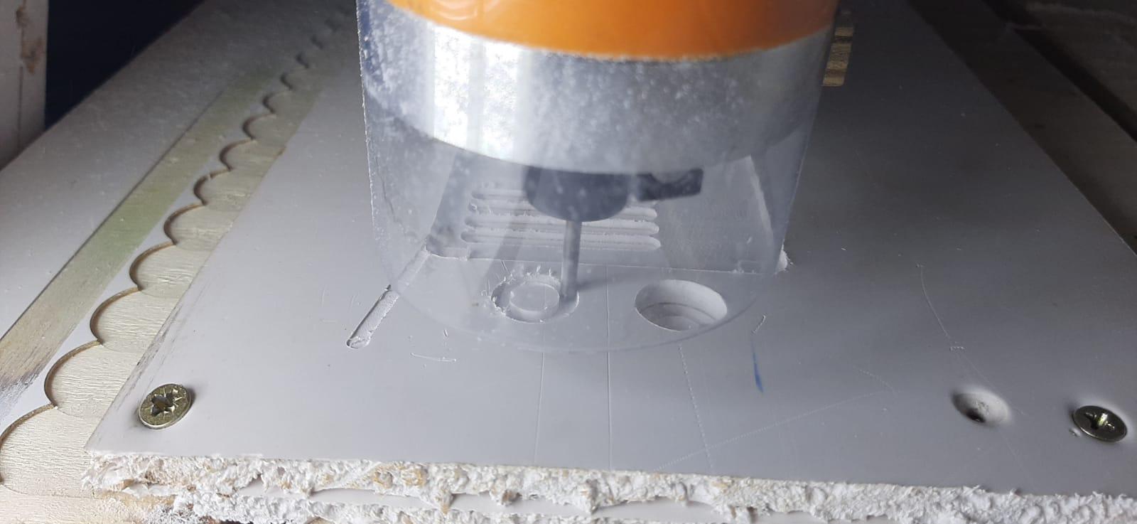
For this project I am using CNC JS to serve as a control interface for CNC machines. It allows you to send GCODE commands to your CNC machine and monitor the machining process. Here's an explanation of how to use it.
1. Connect Your CNC Machine:
Before starting the CNC cutting section, ensure that your CNC machine is connected to the CNC app by selecting the correct port.
2. Uploading GCODE:
Load the GCODE file generated in Fusion 360 into the app. This file contains the instructions for your CNC machine, telling it how to cut and shape the material.
3. Setting the Work Zero:
Define the work zero, which is the reference point for your CNC machine. This point determines where the cutting process begins. Accurately set the work zero to align with the origin used in Fusion 360 during the stock setup phase.
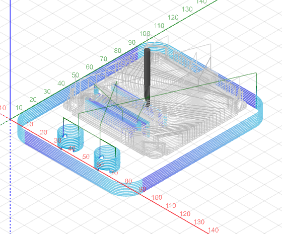
4. Toolpath Visualization:
CNC JS provides a visual representation of the toolpaths based on the uploaded GCODE. You can view the tool's trajectory, helping you confirm that the cutting paths align with your design.
5. Monitor:
As the CNC machine begins the cutting process, CNC.js offers live monitoring capabilities. You can observe the real-time progress of the cutting tool, track any errors or anomalies, and intervene if necessary.
Clean Up
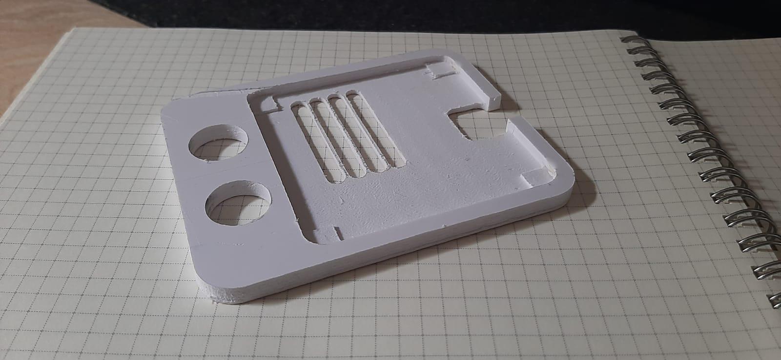
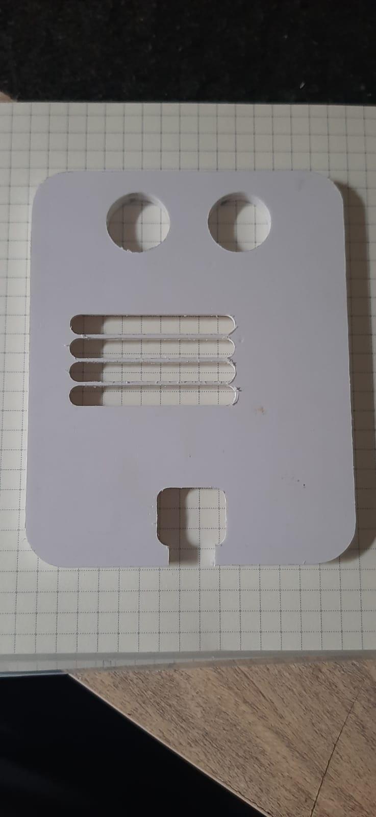
With the milling process completed, it's time to refine the edges using sandpaper. Start with a coarse-grit sandpaper, such as 80 or 120, to tackle noticeable tool marks or excess material. As you advance, transition to finer grits like 220, 400, and beyond for a progressively smoother and polished finish.
Testing
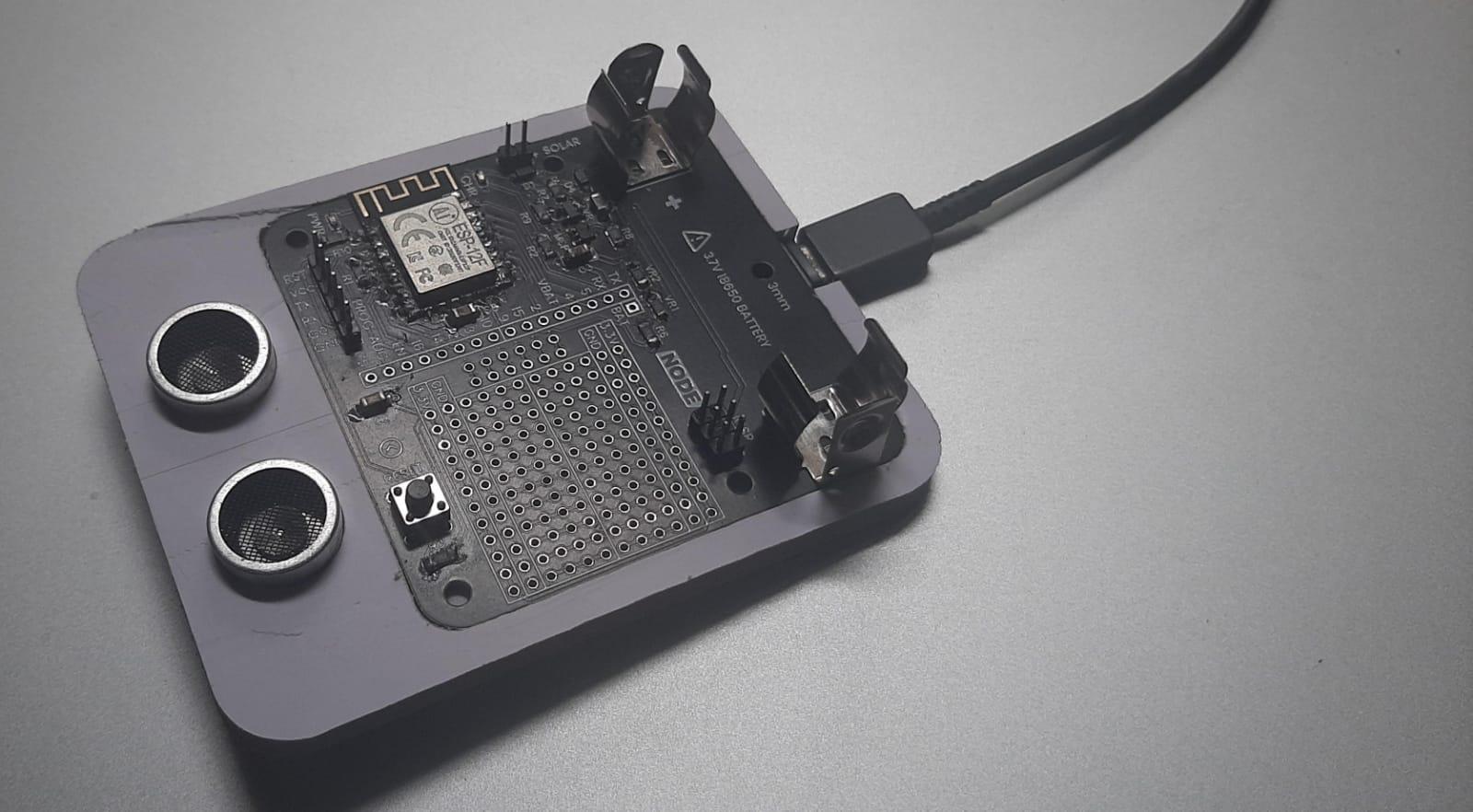
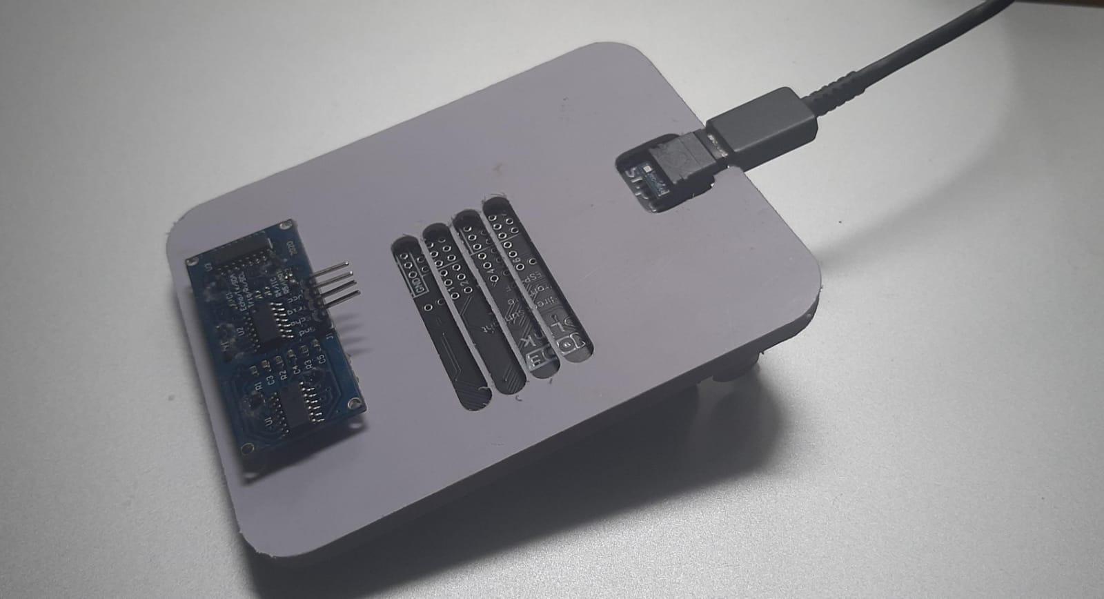
Now, proceed to fix your PCB and other sensors onto the PVC holder securely. This step is pivotal in evaluating the holder's capability to house and support the components appropriately. By conducting this test, you ensure that the design and CNC machining align seamlessly with the specific requirements of your project. If some parts do not fix correctly, you can sand the area or you can start the process again with a more accurate measurement.
I hope you enjoyed this Instructable as much as I love it. Please leave any comments below and consider hitting the favorite button as this would help a lot to me.
Happy making and Thank you for your appreciation!